

Page 1
USER GUIDE
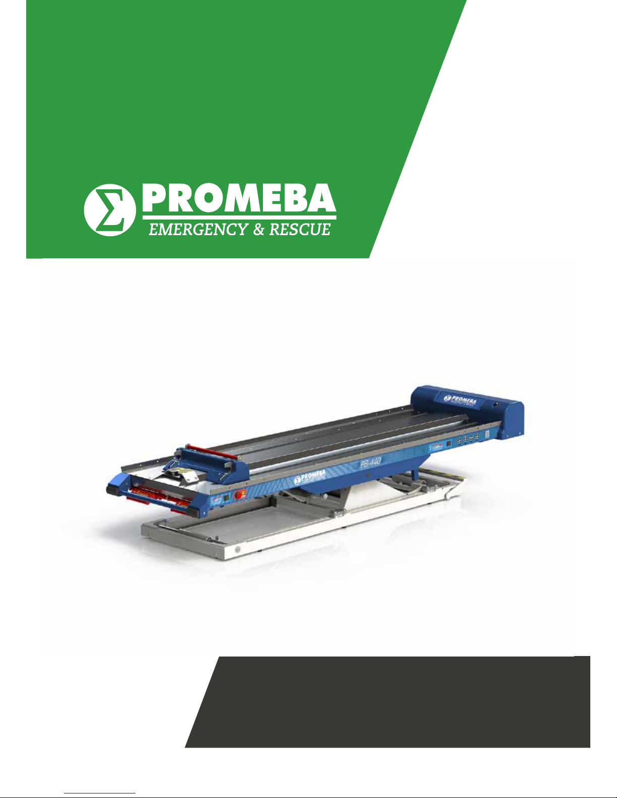
ELEVATOR // PB-440
Review 01/19
Page 2

Page 3
USER MANUAL // ELEVATOR PB-440
Review 01/19
3
INDEX
01 INTRODUCCIÓN
01.1 Using this manual 05
01.2 Technical data sheet 06
02 INSTALATION
02.1 Transporting and unpacking 07
02.2 Anchorage points 08
02.3 Connection to the electric grid 09
03 OPERATING
03.1 Commands 11
03.2 Elements of the manual system 12
03.3 Loading and unloading operation 12
03.4 Electric motion within the ambulance 15
04 MOUNTING AND COMPONENTS
04.1 Main exploded view 17
04.2 Explosionado plataforma superior PB-440/5 18
04.3 Listado de referencias plataforma superior PB-440/5 23
04.4 Explosionado plataforma superior PB-440/2 26
04.5 Listado de referencias plataforma superior PB-440/2 31
04.6 Conjunto plataforma base PB-440/5 · PB-440/2 34
04.7 Listado de referencias conjunto plataforma base PB-440/5 · PB-440/2 35
04.8 Explosionado carro elevador PB-440/5 · PB-440/2 36
04.9 Listado de referencias carro elevador PB-440/5 · PB-440/2 37
04.10 Conjunto guia elevador PB-440/5 · PB-440/2 38
04.11 Listado de referencias guia elevador PB-440/5 · PB-440/2 39
04.12 Explosionado guia elevador PB-440/5 · PB-440/2 40
04.13 Listado de referencias guia elevador PB-440/5 · PB-440/2 41
05 ELECTRICAL CIRCUIT DIAGRAM
05.1 Printed circuit board 43
05.2 PIN conector Hand control 44
06 GENERAL MAINTENANCE 46
07 LEGAL NOTICES 47
08 PRODUCT WARRANTY 48
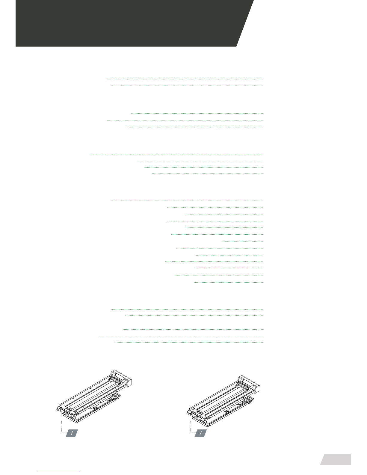
MODEL PB-440/5
WITH LONGITUDINAL
SLIDING PLATFORM
MODEL PB-440/2
WITH LONGITUDINAL
SLIDING PLATFORM
Page 4

Page 5

USER MANUAL // ELEVATOR PB-440
Review 01/19
5
01.1 Using this manual
This manual provides using and maintenance instructions of the product, as well as the way of xing minor
faults that could appear.
It is recommended before the operation of the product
to read carefully this manual in order to avoid damages
caused by a misuse.
Do not lose this document, it should be accessible to
any doubt that could appear by medical personnel.
Remember that a good use and maintenance are necessary for the proper operation of the product.
Each product incorporates an identication sticker with
the serial number and the model. Keep these numbers
so that they can be indicated to the dealer if necessary.
01 INTRODUTION
Page 6
USER MANUAL // ELEVATOR PB-440
Review 01/19
6
01.2 Technical data sheet
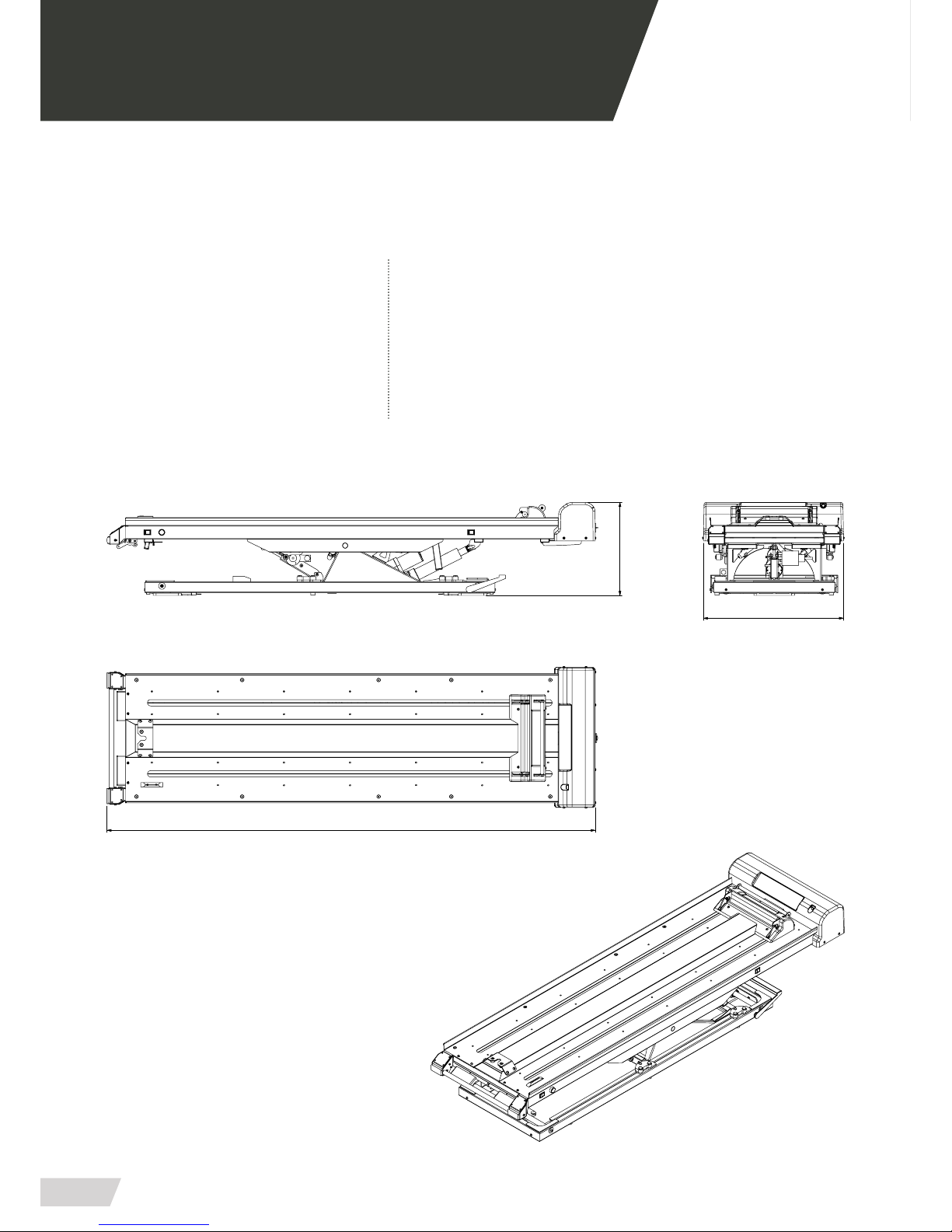
MEASURES AND FEATURES // PB-440/2 + PB-440/5 WITH SIDE MOVEMENT
LENGHT 2018 mm/ 2218 mm ELECTRIC SUPPLY 12 V. CC.
WIDTH 630 mm POWER CONSUMPTION 100A
HEIGHT 425 mm TRENDELEMBURG -15º / +10º
WEIGHT 112-127 Kg HEIGHT LOADING ± 315 mm
MAX. LOAD 250 Kg SIDE MOVEMENT 300 mm
01 INTRODUCTION
630
425
2018 mm/ 2218 mm
Page 7
USER MANUAL // ELEVATOR PB-440
Review 01/19
7
02.1 Transport and unpacking
First carefully remove the packaging to prevent the damage of the outside of the stretcher support.
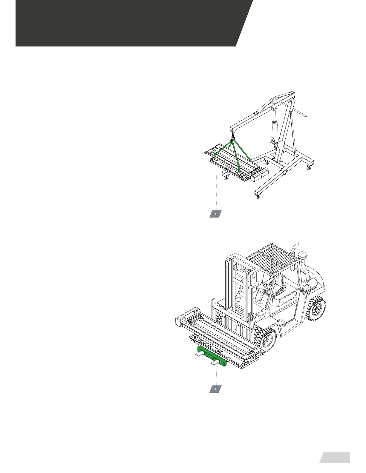
1. Transport with a crane (high load)
· Thread tapes through the upper platform for its transport (as shown in graphs)
· Transport the load level following all the precepts and
regulations for the transport of suspended loads.
2. Transport with a forklift
· Place a pallet or a at surface under the bench and
transport it transversely.
· Do not load the bench directly on the forklift without
a pallet or a at support surface.
· Do not load the bench longitudinally on the forklift if
a suciently long base is not available.
· Every bench has been thoroughly inspected leaving
the factory. To ensure that it hasn’t been damaged during the transport, it is requested to carefully examine
the interior and exterior, and in case of nding any damage, communicate immediately to the installer.
· The bench should be levelled for an optimum performance.
02 INSTALATION
TRANSPORT WITH A CRANE
FIX THE TAPES TO LEVEL THE LOAD WEIGHT
TRANSPORT WITH A FORKLIFT
USE ALWAYS A FLAT SUPPORT SURFACE
Page 8
USER MANUAL // ELEVATOR PB-440
Review 01/19
8
02 INSTALATION
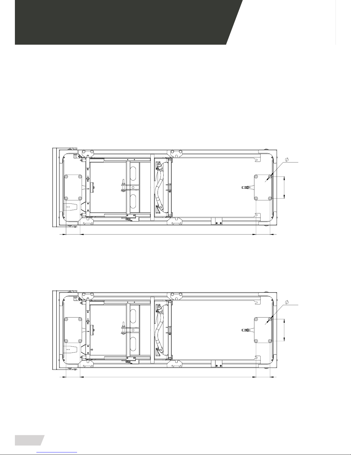
02.2 Anchore points
Before putting the bench into operation, ensure that
each and every anchorage points are placed and
clasped.
ANCHORE FOR PB-440/5
(8 anchorage points)
ANCHORE FOR PB-440/2
(8 anchorage points)
102 1285 102
12,5
159
102 1285 102
159
12,5
Page 9
USER MANUAL // ELEVATOR PB-440
Review 01/19
9
02 INSTALATION
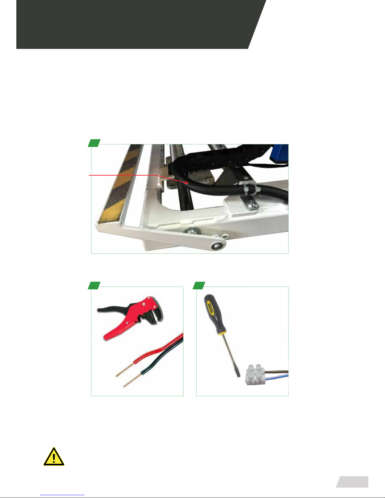
02.3 Connection to the mains power supply
To make the connection follow the steps below.
Be particularly careful when connecting the bench to the required voltage of 12V direct current and
do not leave cables in passageways and or moving elements.
B
Remove the plastic end of the red and
black cables with a thread peeler to
make the connection.
C
Use a power strip and a athead
screwdriver to connect the red and
black cables with the outlet of the
ambulance.
To make the connection locate the black cable located at the front side of the
bench.
MAKE SURE YOU HAVE THE POWER LINE PROPERLY PROTECTED AND ENSURE THAT THE
POWER ALONG THE LINE IS STABLE.
A
Power chord
12V. CC.
Page 10

Page 11
USER MANUAL // ELEVATOR PB-440
Review 01/19
11
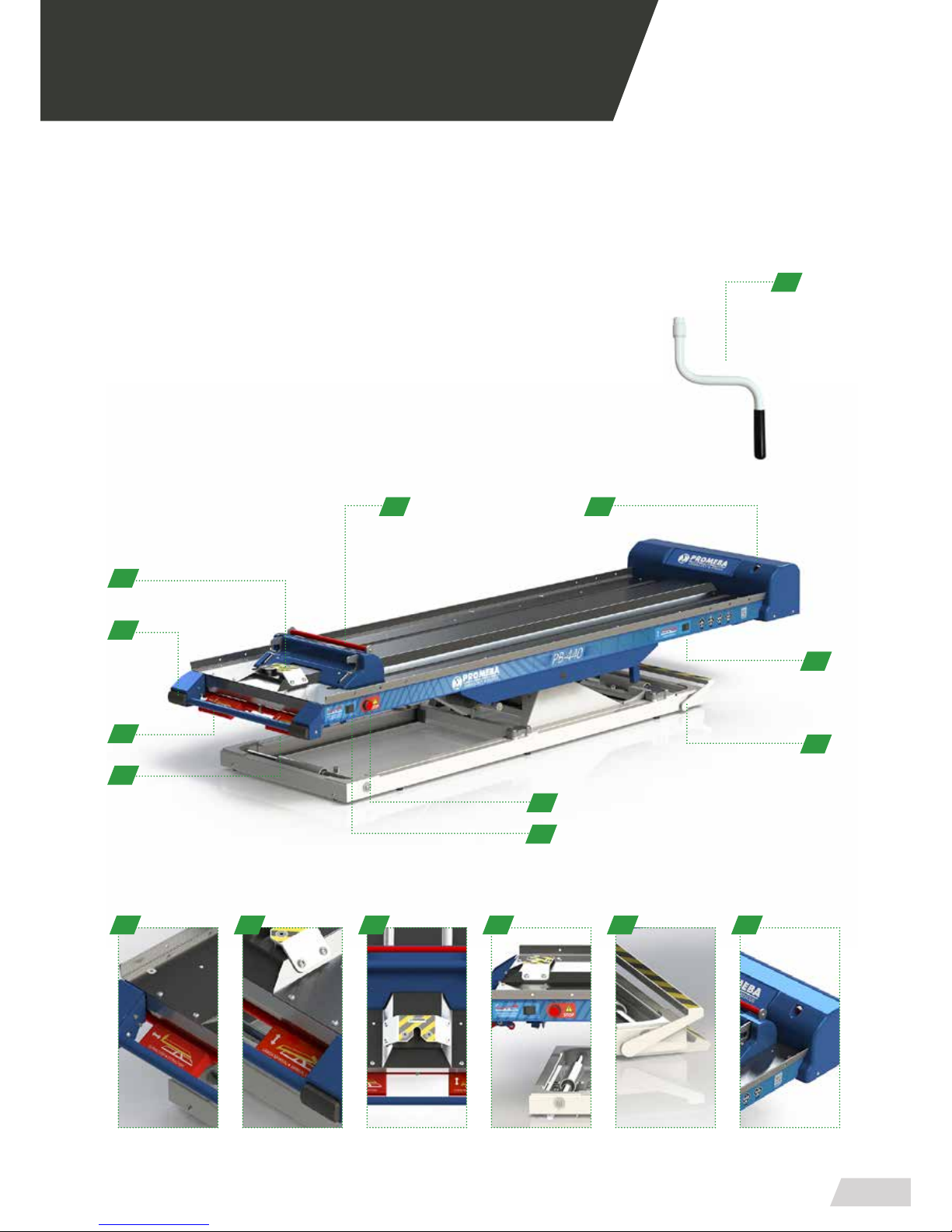
03.1 Commands
1. Crank
2. Third anchor point
3. Security sensors
4. Extraction lever
5. Manual loading lever
6. Charge / discharge button
7. Emergency stop pushbutton
8. Side movement pedal
9. Push button position trendelemburg
10. Status indicator led
11. Manual unlocking hooks
03 OPERATING
11
6
8
1
4
5
7
10
4 5 2 6 8 8
9
3
2
Page 12
USER MANUAL // ELEVATOR PB-440
Review 01/19
12
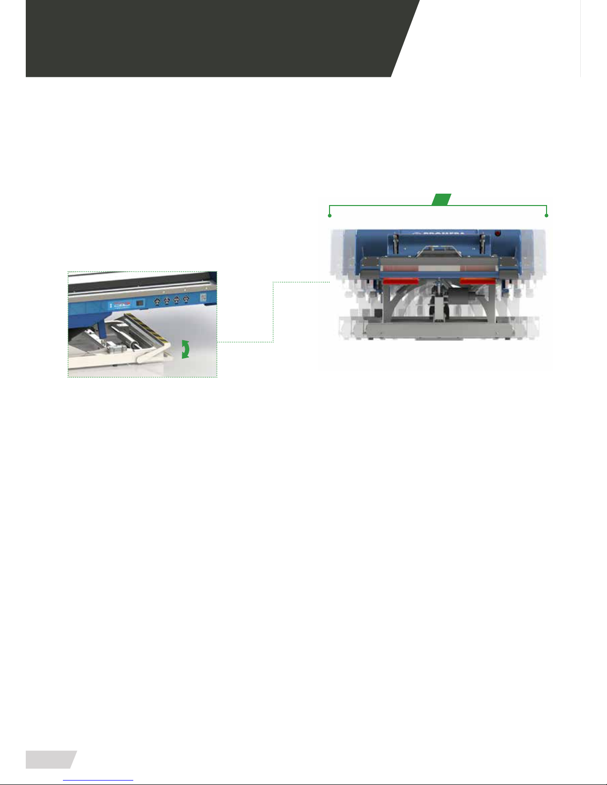
03.2 Elements of the manual system
Lateral displacement
Hand lever
Operate the lever located on the rear of the right side
of the bench, making a slight eort with the foot and
accompanying this movement by sliding your hands.
The total lateral displacement is 300 mm.
300
03 OPERATING
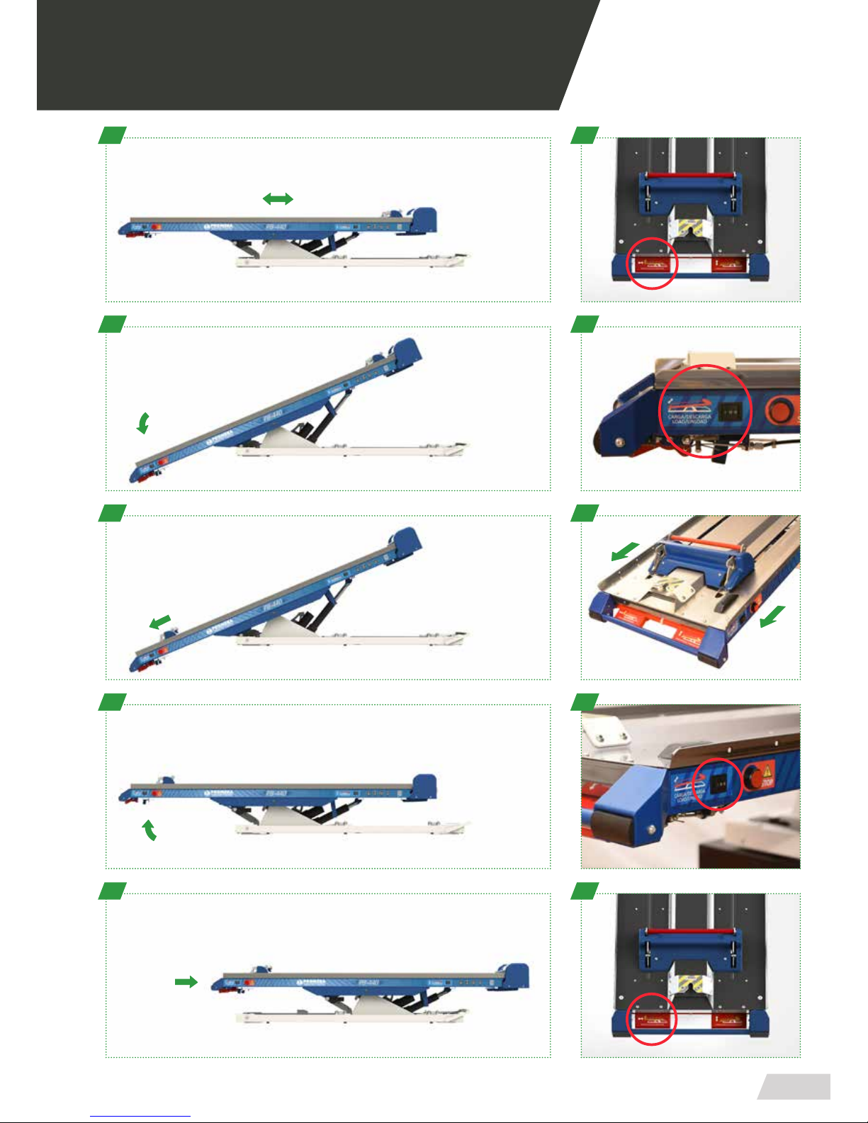
03.3 Loading and unloading operation
Starting from the position in which the bench has been left after the unloading (A):
LOADING
· Load the scoop stretcher until it is locked by the closure
· Fold the loading ramp
· Pull the loading lever
· Use the hand control to complete the loading movement (Optional)
· The bench should complete automatically the movement to zero position (B)
· Slide the tray until hearing “clack”; locking position is completed (C)
· You can keep the scoop stretcher by xing it to the front hooks (4)
UNLOADING
· Extract the tray with the unloading lever (5)
· Use the hand control to complete the loading movement (Optional)
· The tray should automatically lean (A)
· Open the loading ramp (2)
· Release the hook by activating the lever (1)
· The scoop stretcher should lean out; hold it with the hands (A)
· Remove the scoop stretcher
Page 13
USER MANUAL // ELEVATOR PB-440
Review 01/19
13
03 OPERATING
A 1
B
C
D
E
2
3
4
5
Page 14

Page 15
USER MANUAL // ELEVATOR PB-440
Review 01/19
15
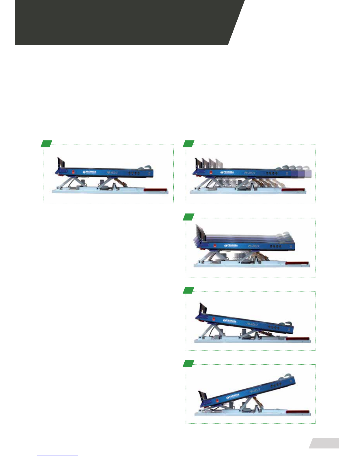
03.4 Electric motion within the ambulance
The following predened movements can be completed with the hand control.
ZERO POSITION OR REST POSITION
Zero position, also known as rest position, is where the bench is fully horizontal and folded on itself (1). This position can be
switched with the hand control by pressing the button (No. 6)
The bench can be longitudinally moved if the optional system for such use is available (2)
1
ASCENT / DESCENT
Press the button Ascent (No. 1) or Descent (No. 2)
The movement takes place while the button is being pressed
To stop the movement, release the button
The bench ascends or descends horizontally with the actuators, slowly sliding to the chosen position and stopping at
the desired point (3)
TRENDELEMBURG (Proclive / Declive)
Press the button (No. 3) or (No. 4)
The movement takes place while the button is being pressed
To stop the movement, release the button
· Position trendelemburg proclive (4):
In this position the bench is elevated from the position in
which the patient’s head is placed, diagonally. To access this
movement, press button No. 3
· Position trendelemburg declive (5):
In this position the bench is elevated from the position in
which the patient’s feet are placed, diagonally. To access this
movement, press button No. 4
2
3
4
5
03 OPERATING
Page 16

Page 17
USER MANUAL // ELEVATOR PB-440
Review 01/19
17
04 MOUNTING AND COMPONENTS
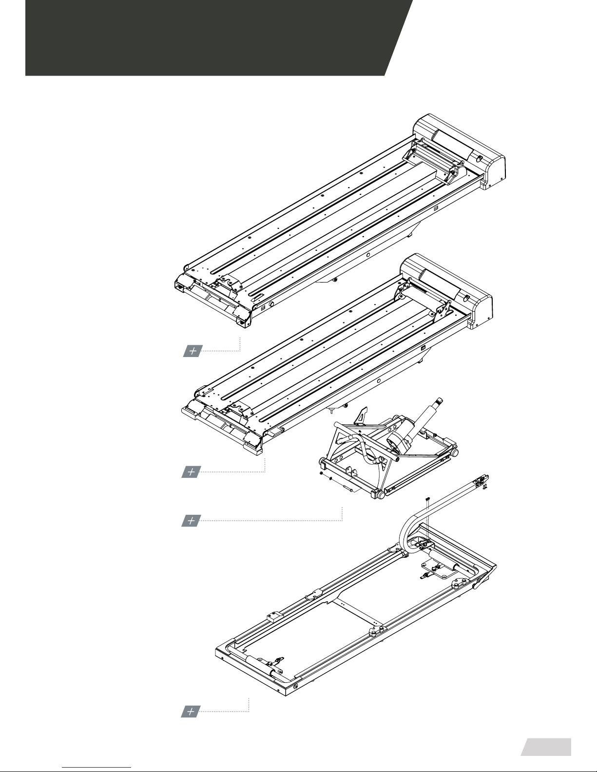
04.1 Main exploded views
PB-440/5
TOP PLATFORM
SEE DETAIL ON PAGE 18
PB-440/2
TOP PLATFORM
SEE DETAIL ON PAGE 26
PB-440/5 · PB-440/2
BASE PLATFORM
SEE DETAIL ON PAGE 34
PB-440/5 · PB-440/2
ELEVATOR GUIDE SET
SEE DETAIL ON PAGE 38
Page 18
USER MANUAL // ELEVATOR PB-440
Review 01/19
18
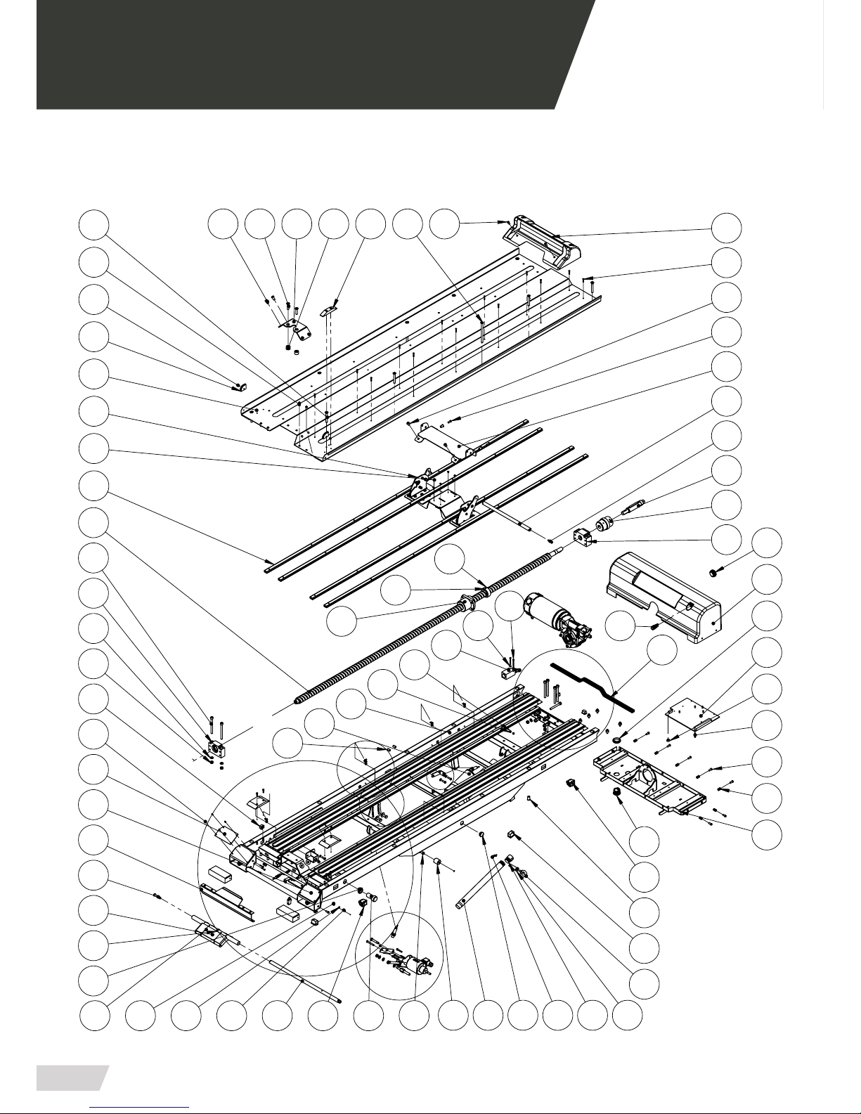
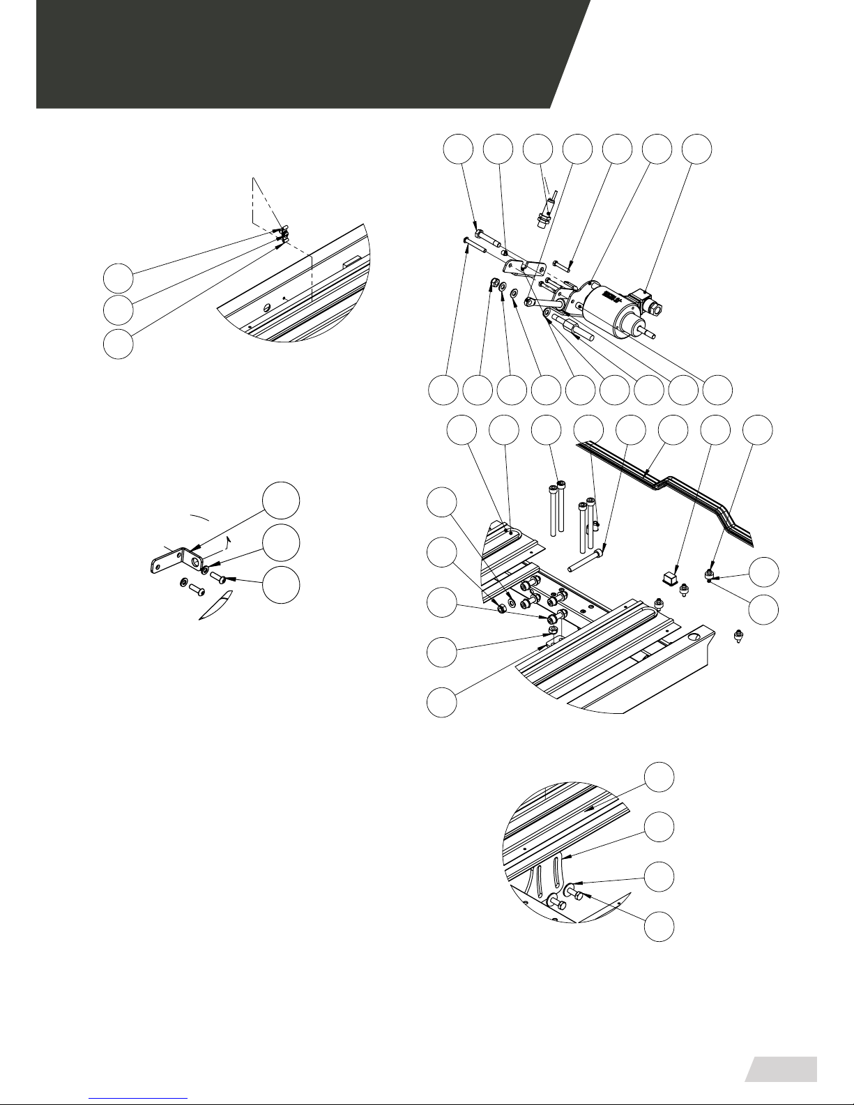
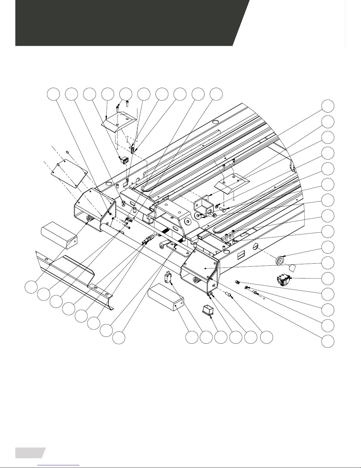
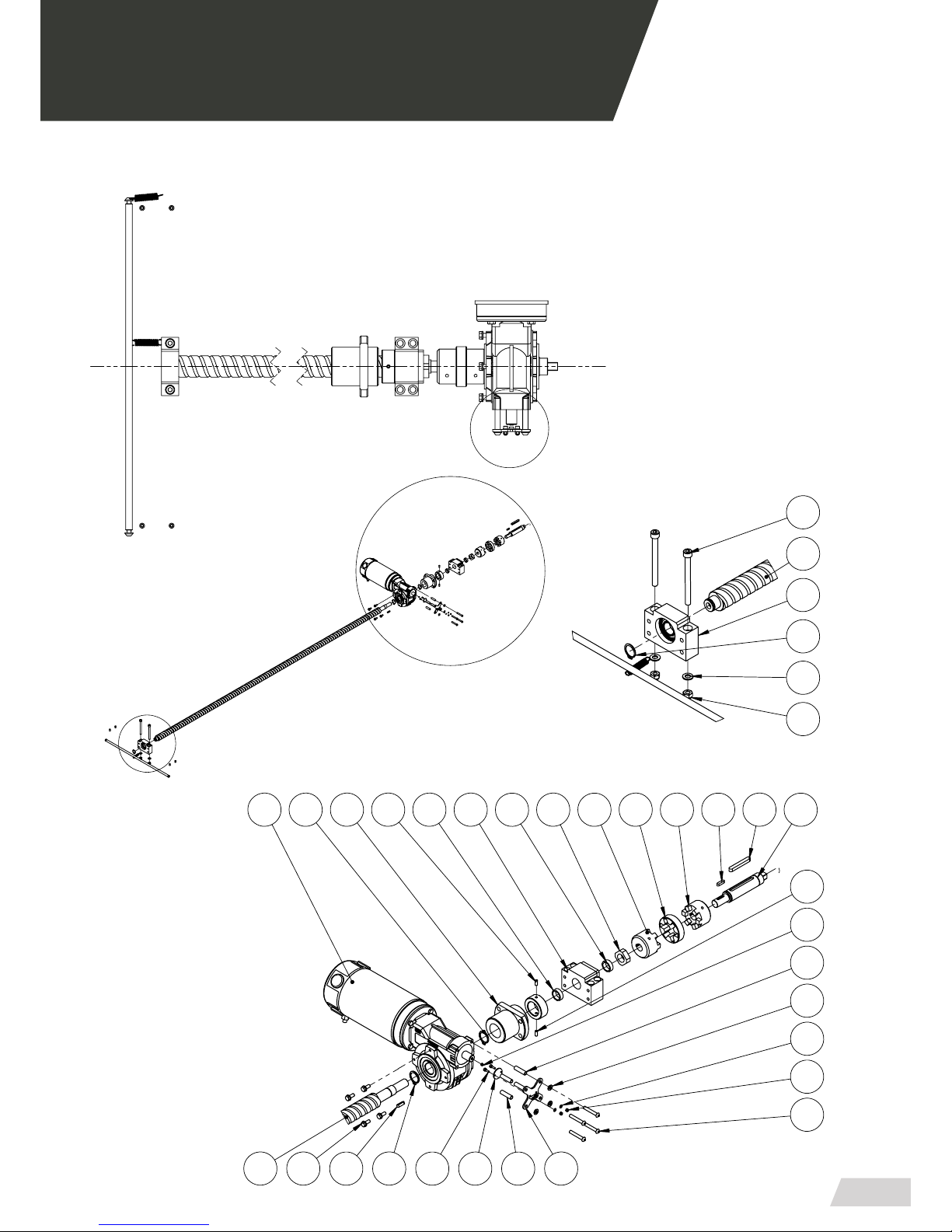
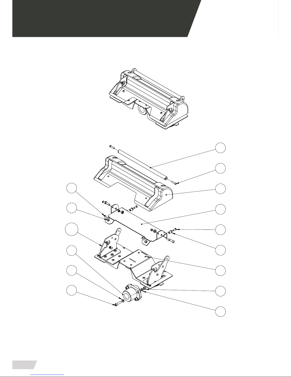
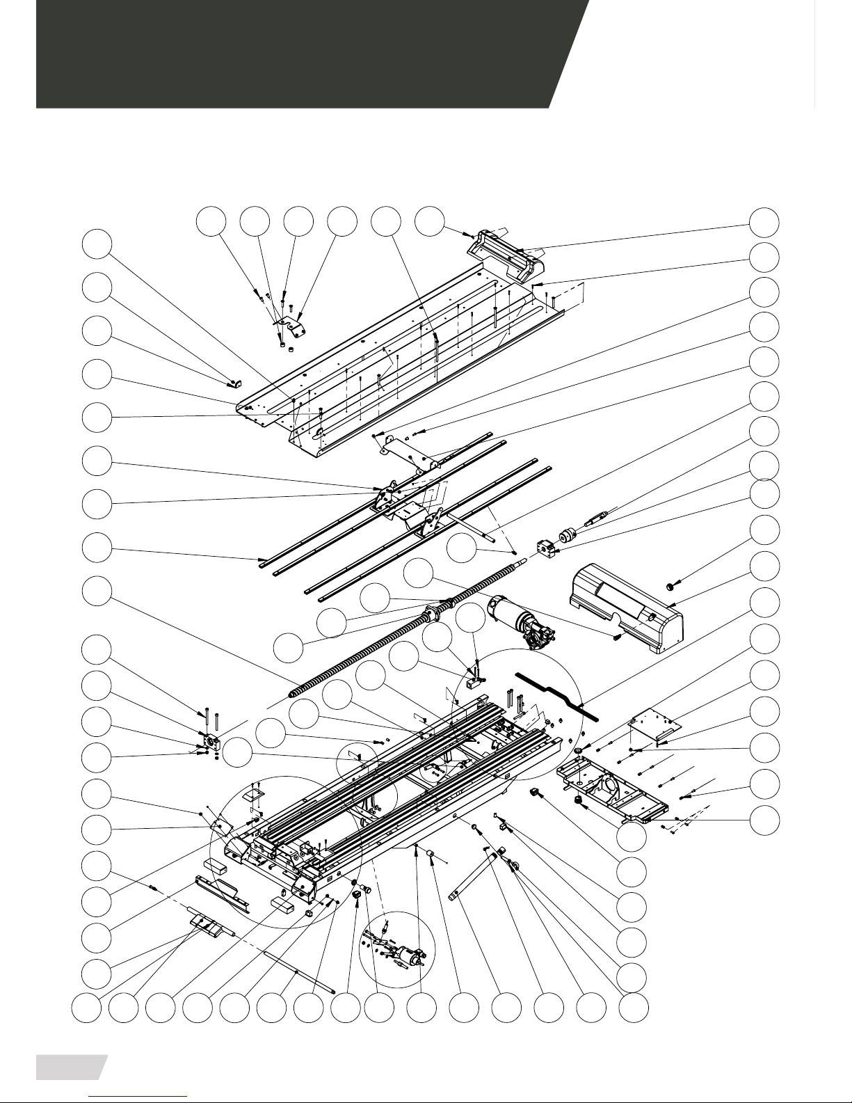
04.2 Top platform set PB-440/5
72
109
50
53112 733619
38
109
52
49
81
39
100
109
109
46
3
29
44
127
41
1
42
98
69
85
8
4
68
6
45
64
123
80
9
20
40 71
18
7
75
82
105
8
128
67
74
127
97
98
43
2
25
99
83
79
10
108
110
17
102
37
54
21
84
27
15
51
65
94
47
47
933
55
16
103
130
A
C
B
D
E
AA
Page 19
USER MANUAL // ELEVATOR PB-440
Review 01/19
19
126
128
DETALLE AA
ESCALA 1 : 5
126
94
65
?
23
2270
24
77
94 7694 32
129
115
DETALLE A
ESCALA 1 : 5
14
78
62
110
94
65
DETALLE C
ESCALA 1 : 5
11
58 63
80
101106655694100
108
92
26
DETALLE D
ESCALA 1 : 5
89
14
113
86
DETALLE E
ESCALA 1 : 5
13
04.2 Top platform set PB-440/5
Page 20
USER MANUAL // ELEVATOR PB-440
Review 01/19
20
04 MOUNTING AND COMPONENTS
72
66
ESCALA 1 : 4
DETALLE B
111
126
114
71
91
93
12
107
?
8
124
127
59
40
114
123
5
63
89
109
65
130
35
87
88
96
132
95 109
57
86
132
40
41
34
111
108
128
04.2 Top platform set PB-440/5
Page 21
USER MANUAL // ELEVATOR PB-440
Review 01/19
21
04 MOUNTING AND COMPONENTS
121
ESCALA 1 : 7
DETALLE M
91
61
21
15 15
15
17
17
15
61
60
27
37
84
17
84
121
118
31
119
90
116120 30
117
86
122
117
94
DETALLE N
ESCALA 1 : 5
65
16
100
37
127
M
N
Z
04.2 Top platform set PB-440/5
Page 22
USER MANUAL // ELEVATOR PB-440
Review 01/19
22
04 MOUNTING AND COMPONENTS
65
49
81
109
82
109
50
82
112
51
46
104
94
21
94
04.2 Top platform set PB-440/5
Page 23

USER MANUAL // ELEVATOR PB-440
Review 01/19
23
04 MOUNTING AND COMPONENTS
04.3 Bill of materials TOP PLATFORM SET PB-440/5
NUM. ELEMENT CODE - DESCRIPTION UNITS
02.1 PB4405-05012 - SUBCONJUNT PLATAFORMA SUPERIOR
LLARGA
1
02.2 PB4400-00300 - CONJUNT COSTELLA ARRASTRE 1
02.3 PB4400-00390 - FINAL DE CARRERA 1
02.4 PB4100-04161 - SUBC EIX GIR MANETES FRONTALS 1
02.5 PB4405-00032 - SUBCONJUNT TOPE COSTELLA 2
02.6 PB4100-04542 - MANETA FRONTAL ESQUERRA 1
02.7 PB4100-04402 - MANETA FRONTAL DRETA 1
02.8 PB4550-04160 - PULSADOR PARO EMERGENCIa 1
02.9 PB4400-00180 - CILINDRE ELECTRIC VASTEG 1
02.10 PB4400-00180 - CILINDRE ELECTRIC MOTOR 1
02.11 PB4400-04202 - PLAQUETA COLLADA SOPORT
BISENFI POSTERIOR
2
02.12 PB4400-04182 - PLAQUETA COLLADA SOPORT BISENFI 1
02.13 PB4400-00492 - SOPORT DETECTOR CARREGA 1
02.14 PB4400-00380 - DETECTOR INDUCTIU M12 PNP 3
02.15 PB4400-00350 - SOPORT RODAMENTS BF20 1
02.16 PB4400-00360 - SOPORT RODAMENTS BK20 1
02.17 PB4400-00240 - SAMIFLEX A0 MECANITZAT 1
02.19 PB4400-00612 - TERCER PUNT ANCLATJE ELEVADOR 1
02.22 PB4400-00502 - SOPORT MECLOCK I ELECTROIMAN 1
02.23 PB4100-00440 - VÀSTEG FIXADOR MECLOCK CILÍNDRIC 1
02.24 PB4100-00440 - FIXADOR MECLOCK CILÍNDRIC 1
02.25 PB4400-00421 - EIX GIR ACTUADOR 1
02.26 PB4100-04732 - PLETINA REGULACIO CARREGA 2
02.27 PB4400-00471 - EIX MOTOR 1
02.28 PB4400-00320 - ELECTROIMAN ECH65-15 1
02.29 PB4400-00170 - PLACA ELECTRONICA 1
02.30 PB4400-00660 - ENCODER 1
02.31 PB4400-00660 - IMAN ENCODER ELEVADOR 1
02.33 PB4400-00590 - CLIP SUBJECCIO ACTUADOR 1
02.34 PB4400-05190 - PULSADOR ENTRADA CAMILLA 2
02.35 MICRO83160CR - MICRO PULSADOR CROUZET 2
02.37 PB4405-00060 - BISENFI ELEVADOR 1
02.38 PB4405-00010 - SAFATA INOXIDABLE LLARGA 1
02.39 PB4405-00021 - TUB REFORÇ SAFATA 4
02.40 PB4010-00151 - SUJETACABLES 2
02.41 TAPPLA-30x20 - TAPON PLASTICO INTERIOR 30x20 4
Page 24

USER MANUAL // ELEVATOR PB-440
Review 01/19
24
04 MOUNTING AND COMPONENTS
04.3 Bill of materials TOP PLATFORM SET PB-440/5
NUM. ELEMENT CODE - DESCRIPTION UNITS
02.42 TAP-PLASTØ25 - TAPON PLASTICO FINAL Ø25 - MOD. 17-25 2
02.43 PB4400-00122 - SUBCONJUNT SOPORT MOTOR 1
02.44 PB4400-00670 - LLUM JUMBOLED VERMELL 1
02.45 PB4400-00260 - PROTECCIO FRONTAL 1
02.46 40022 - TOPE POTA PVC MOSS 4
02.47 PB4400-00670 - ZUMBADOR 1
02.48 PB4100-00460 - ANGLE SUPORT PER TENSOR CABLE 2
02.49 PB4400-00082 - SUBCONJUNT BARRA DESENGATILLADORA 1
02.50 PB4400-00812 - TAPA GANXOS TERMOCONFORMADA 1
02.51 PB4400-00802 - SUPORT TAPA GANXOS DAVANTERS 1
02.52 PB4400-00822 - TAPA MOTOR TERMOCONFORMADA 1
02.53 PB4400-00100 - PATI GOMA DESBLOQUEIG RODES
CAMILLAS
1
02.54 PB4405-05071 - TOPALL BISENFI ELEVADOR 1
02.55 TAP-PLASTØ35 - TAPON PLASTICO FINAL Ø35 - MOD. 17-35 1
02.56 PB4400-05220 - CEPILLO ALUMINI H32534B 4
02.57 PA5100-05031 - MOLLA ESPIRAL 2
02.58 PB4400-00170 - INTERRUPTOR PLACA ELECTRONICA 1
02.59 PB4400-05200 - MOLLA CARREGA MITJA Ø20xØ10x64mm 2
02.60 PB4400-00640 - XAVETA D-6885 8x60 1
02.61 PB4400-00650 - XAVETA D-6885 5x20 2
02.64 PB4400-05230 - SUFRIDERA RAMPES ATAC CAMILLA
ESQUERRA
1
02.66 PB4180-03181 - EIX GIR MANETES BANCADA 1
02.76 PB4100-00411 - SUBJECCIO SUPERIOR AMORTITZER 1
02.77 PB4100-00341 - SOPORT FIXADOR 1
02.79 PB4550-01300 - SEPARADOR HEXAGONAL
FEMELLA-FEMELLA M3x25
1
02.87 87 PB4100-04840 - TENSOR REGULABLE 2
02.102 PB4184-00060 - CANTONERA PLASTIC SAFATA 2
02.106 PB4400-00700 - CUBRE PERFIL AUTO-ADHESIU SPGSG-6 2
02.110 EC-051129-2 - PERFIL CO-EXTRUSIONADO 1
02.111 PB4405-00090 - PATI TERCER PUNT ELEVADOR PB-440 2
02.115 PB4010-00060 - TERMINAL FUNDA CABLES T01-05 3
02.116 PB4400-00370 - MOTOR-REDUCTOR M050 FB 1-7 12V DC
800W S2 3000RPM
1
02.117 PB4402-05232 - SUPORT ENCODER MOTOR 1
02.124 PB4400-04190 - CLIP ALUMINI Ø4.8 AC-3 6
Page 25

USER MANUAL // ELEVATOR PB-440
Review 01/19
25
04 MOUNTING AND COMPONENTS
04.3 Bill of materials TOP PLATFORM SET PB-440/5
NUM. ELEMENT CODE - DESCRIPTION UNITS
02.127 PB4400-00410 - PULSADOR ROCKER
(RL23-23-C-6-BKBK-P4-3)
2
02.128 PB4400-00410 - PULSADOR ROCKER
(RL23-23-C-6-BKBK-P4-3)
2
02.129 PB4400-05232 - SUPORT PER DETECTOR INDUCTIU
CENTRAL
1
02.130 PB4400-05210 - SUFRIDERA RAMPES ATAC CAMILLA DRETA 1
Page 26
USER MANUAL // ELEVATOR PB-440
Review 01/19
26
04 MOUNTING AND COMPONENTS
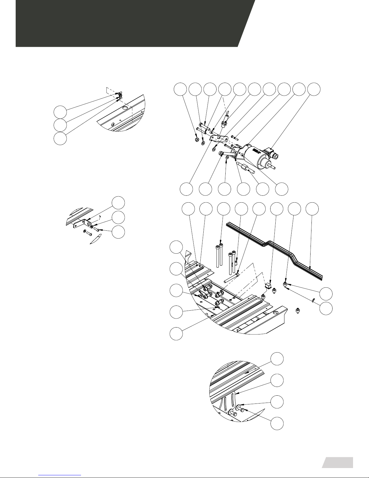
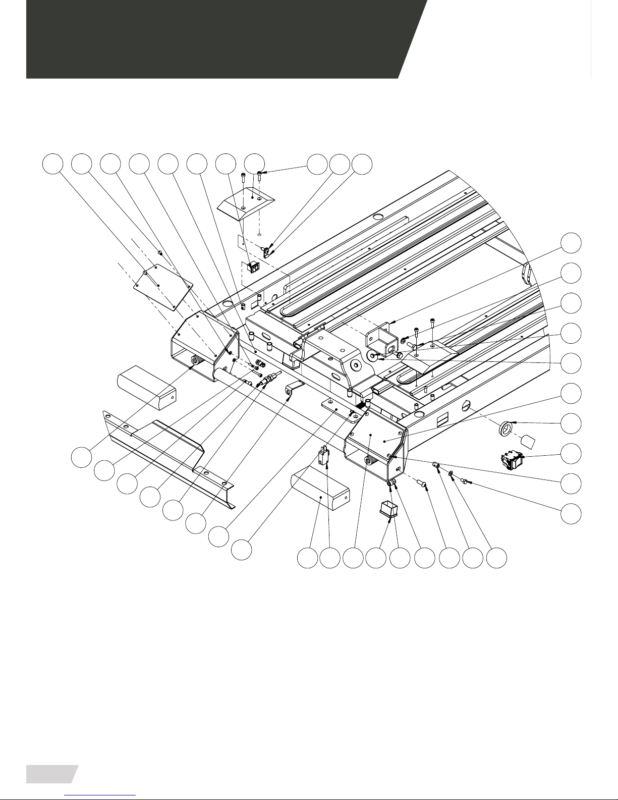
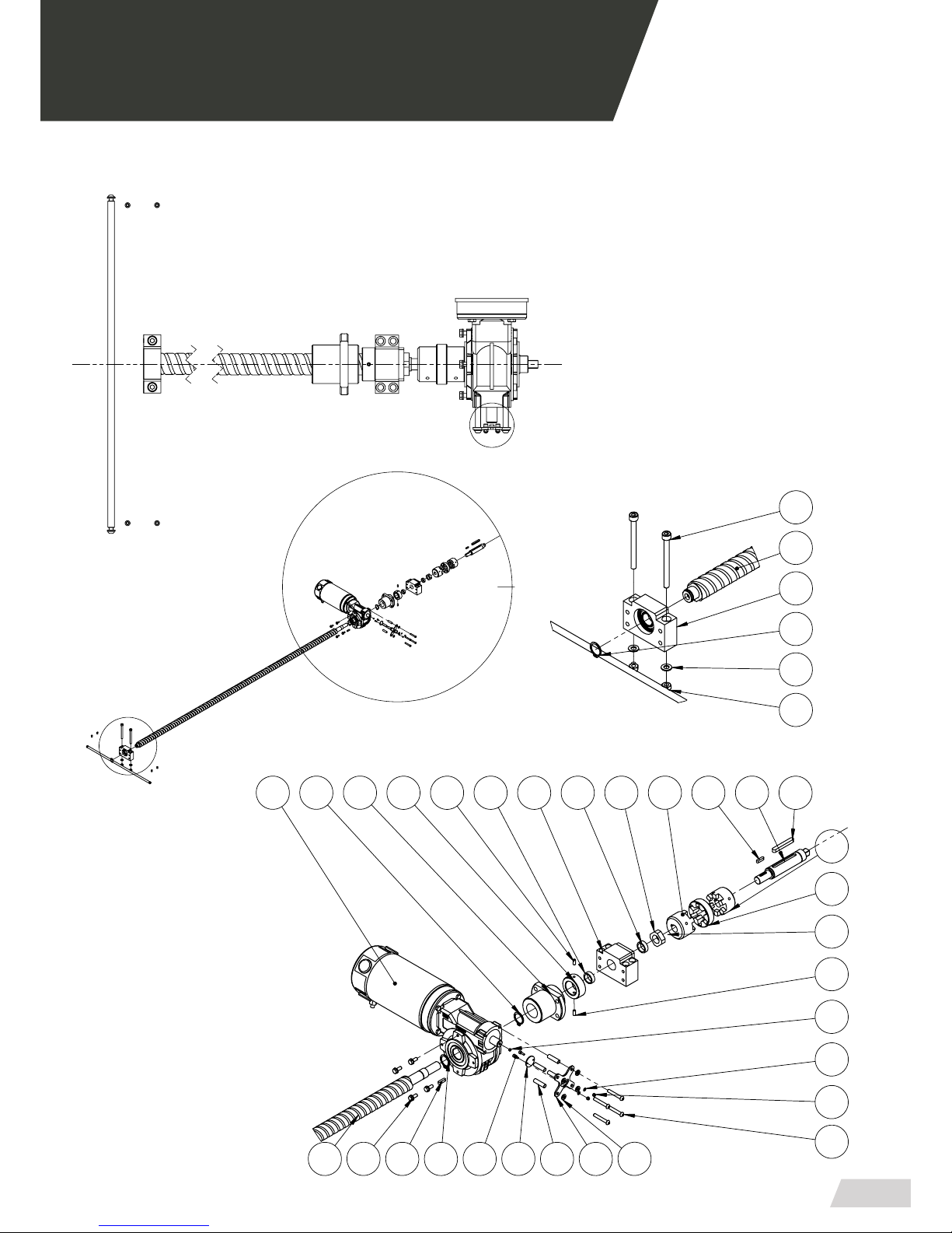
04.4 Top platform set PB-440/2
33
75
50
110
7236
19
38
75
105
15
39
44
3
79
29
83
52
81
9
125
20
68
85
8
18
7
6
84
25
45
63
121
80
42
1
126
17
40 70
71
74
49
82
46
75
51
66
73
125
97
98
43
2
99
98
10
107
102
103
16
37
21
27
108
53
47
41
4
47
100
64
94
67
54
128
A
B
E
C
D
AA
Page 27
USER MANUAL // ELEVATOR PB-440
Review 01/19
27
04 MOUNTING AND COMPONENTS
126
127
DETALLE AA
ESCALA 1 : 5
126
ESCALA 1 : 5
DETALLE A
78
76
?
24
32
77
69
94
94
127
64
94
23
1092214
94
100 57
61
108107
104
11
62
DETALLE C
ESCALA 1 : 5
80
64
64
55
101601
ESCALA 1 : 5
DETALLE D
26
89
92
14
111
86
DETALLE E
ESCALA 1 : 5
13
04.4 Top platform set PB-440/2
Page 28
USER MANUAL // ELEVATOR PB-440
Review 01/19
28
04 MOUNTING AND COMPONENTS
56
75
64
9596
130
DETALLE B
ESCALA 1 : 4
41
121
?
112
75
113
8
125
71
91 65
128 40
123
12
121
126
35
122
93
86
5
40
62
58
89
34
88
128
87
70
63
04.4 Top platform set PB-440/2
Page 29
USER MANUAL // ELEVATOR PB-440
Review 01/19
29
04 MOUNTING AND COMPONENTS
M
N
Z
60
DETALLE M
ESCALA 1 : 7
37
15
123
53
59
17
15
17
47
60
15 27
15
116
84
119
114
119
90
91
30
31
21
86
115
17
84
113
122
64
DETALLE N
ESCALA 1 : 5
94
16
100
37
123
04.4 Top platform set PB-440/2
Page 30
USER MANUAL // ELEVATOR PB-440
Review 01/19
30
04 MOUNTING AND COMPONENTS
35
130
162
34
163
34
34
131
163
27
132
126
185
177
35
86
177
34
40
43
04.4 Top platform set PB-440/2
Page 31

USER MANUAL // ELEVATOR PB-440
Review 01/19
31
04 MOUNTING AND COMPONENTS
04.5 Bill of materials TOP PLATFORM SET PB-440/2
NUM. ELEMENT CODE - DESCRIPTION UNITS
03.1 PB4402-05012 - SUBCONJUNT PLATAFORMA SUPERIOR
CORTA
1
03.2 PB4400-00300 - CONJUNT COSTELLA ARRASTRE 1
03.3 PB4400-00390 - FINAL DE CARRERA 1
03.4 PB4100-04161 - SUBC EIX GIR MANETES FRONTALS 1
03.5 PB4405-00032 - SUBCONJUNT TOPE COSTELLA 2
03.6 PB4100-04542 - MANETA FRONTAL ESQUERRA 1
03.7 PB4100-04402 - MANETA FRONTAL DRETA 1
03.8 PB4550-04160 - PULSADOR PARO EMERGENCIA 1
03.9 PB4400-00180 - CILINDRE ELECTRIC VASTEG 1
03.10 PB4400-00180 - CILINDRE ELECTRIC MOTOR 1
03.11 PB4400-04202 - PLAQUETA COLLADA SOPORT
BISENFI POSTERIOR
2
03.12 PB4400-04182 - PLAQUETA COLLADA SOPORT BISENFI 1
03.13 PB4400-00492 - SOPORT DETECTOR CARREGA 1
03.14 PB4400-00380 - DETECTOR INDUCTIU M12 PNP 3
03.15 PB4400-00350 - SOPORT RODAMENTS BF20 1
03.16 PB4400-00360 - SOPORT RODAMENTS BK20 1
03.17 PB4400-00240 - SAMIFLEX A0 MECANITZAT 1
03.19 PB4400-00612 - TERCER PUNT ANCLATJE ELEVADOR 1
03.22 PB4400-00502 - SOPORT MECLOCK I ELECTROIMAN 1
03.23 PB4100-00440 - VÀSTEG FIXADOR MECLOCK CILÍNDRIC 1
03.24 PB4100-00440 - FIXADOR MECLOCK CILÍNDRIC 1
03.25 PB4400-00421 - EIX GIR ACTUADOR 1
03.26 PB4100-04732 - PLETINA REGULACIO CARREGA 2
03.27 PB4400-00471 - EIX MOTOR 1
03.28 PB4400-00320 - ELECTROIMAN ECH65-15 1
03.29 PB4400-00170 - PLACA ELECTRONICA 1
03.30 PB4400-00660 - ENCODER 1
03.31 PB4400-00660 - IMAN ENCODER ELEVADOR 1
03.33 PB4400-00590 - CLIP SUBJECCIO ACTUADOR 1
03.34 PB4400-05190 - PULSADOR ENTRADA CAMILLA 2
03.35 MICRO83160CR - MICRO PULSADOR CROUZET 2
03.37 PB4402-00060 - BISENFI ELEVADOR CURT 1
03.38 PB4402-00010 - SAFATA INOXIDABLE CURTA 1
03.39 PB4402-00021 - TUB REFORÇ SAFATA CURTA 4
03.40 PB4010-00151 - SUJETACABLES 2
03.41 TAPPLA-30x20 - TAPON PLASTICO INTERIOR 30x20 4
Page 32

USER MANUAL // ELEVATOR PB-440
Review 01/19
32
04 MOUNTING AND COMPONENTS
04.5 Bill of materials TOP PLATFORM SET PB-440/2
NUM. ELEMENT CODE - DESCRIPTION UNITS
03.42 TAP-PLASTØ25 - TAPON PLASTICO FINAL Ø25 - Mod. 17-25 2
03.43 PB4400-00122 - SUBCONJUNT SOPORT MOTOR 1
03.44 PB4400-00670 - LLUM JUMBOLED VERMELL 1
03.45 PB4400-00260 - PROTECCIO FRONTAL 1
03.46 40022 - TOPE POTA PVC MOSS 4
03.47 PB4400-00670 - ZUMBADOR 1
03.48 PB4100-00460 - ANGLE SUPORT PER TENSOR CABLE 2
03.49 PB4400-00082 - SUBCONJUNT BARRA DESENGATILLADORA 1
03.50 PB4400-00812 - TAPA GANXOS TERMOCONFORMADA 1
03.51 PB4400-00802 - SUPORT TAPA GANXOS DAVANTERS 1
03.52 PB4400-00822 - TAPA MOTOR TERMOCONFORMADA 1
03.53 PB4405-05071 - TOPALL BISENFI ELEVADOR 1
03.54 TAP-PLASTØ35 - TAPON PLASTICO FINAL Ø35 - MOD. 17-35 1
03.55 PB4402-05220 - CEPILLO ALUMINI H32534B CURT 4
03.56 PA5100-05031 - MOLLA ESPIRAL 1
03.57 PB4400-00170 - INTERRUPTOR PLACA ELECTRONICA 1
03.58 PB4400-05200 - MOLLA CARREGA MITJA Ø20xØ10x64mm 2
03.59 PB4400-00640 - XAVETA D-6885 8x60 1
03.60 PB4400-00650 - XAVETA D-6885 5x20 2
03.63 PB4400-05230 - SUFRIDERA RAMPES ATAC CAMILLA
ESQUERRA
1
03.65 PB4180-03181 - EIX GIR MANETES BANCADA 1
03.76 PB4100-00411 - SUBJECCIO SUPERIOR AMORTITZER 1
03.77 PB4100-00341 - SOPORT FIXADOR 1
03.79 PB4550-01300 - SEPARADOR HEXAGONAL FEMELLAFEMELLA M3x25
1
03.84 3160205121 ESPARREC D-913 M5x12 2
03.87 PB4100-04840 - TENSOR REGULABLE 2
03.102 PB4184-00060 - CANTONERA PLASTIC SAFATA 2
03.106 PB4402-00700 - CUBRE PERFIL AUTO-ADHESIU SPGSG-6 2
03.108 EC-051129-2 - PERFIL CO-EXTRUSIONADO 1
03.109 PB4010-00060 - TERMINAL FUNDA CABLES T01-05 3
03.112 PB4405-00090 - PATI TERCER PUNT ELEVADOR PB-440 2
03.114 PB4400-00370 - MOTOR-REDUCTOR M050 FB 1-7 12V DC
800W S2 3000RPM
1
03.116 PB4402-05232 - SUPORT ENCODER MOTOR 1
03.122 PB4400-04190 - CLIP ALUMINI Ø4.8 AC-3 6
Page 33

USER MANUAL // ELEVATOR PB-440
Review 01/19
33
04 MOUNTING AND COMPONENTS
04.5 Bill of materials TOP PLATFORM SET PB-440/2
NUM. ELEMENT CODE - DESCRIPTION UNITS
03.125 PB4400-00410 - PULSADOR ROCKER
(RL23-23-C-6-BKBK-P4-3)
2
03.126 PB4400-05240 - PULSADOR ROCKER
(RL310-11-G-2-BKBK-P5-0)
1
03.127 PB4400-05232 - SUPORT PER DETECTOR INDUCTIU
CENTRAL
1
03.128 PB4400-05210 - SUFRIDERA RAMPES ATAC CAMILLA DRETA 1
Page 34
USER MANUAL // ELEVATOR PB-440
Review 01/19
34
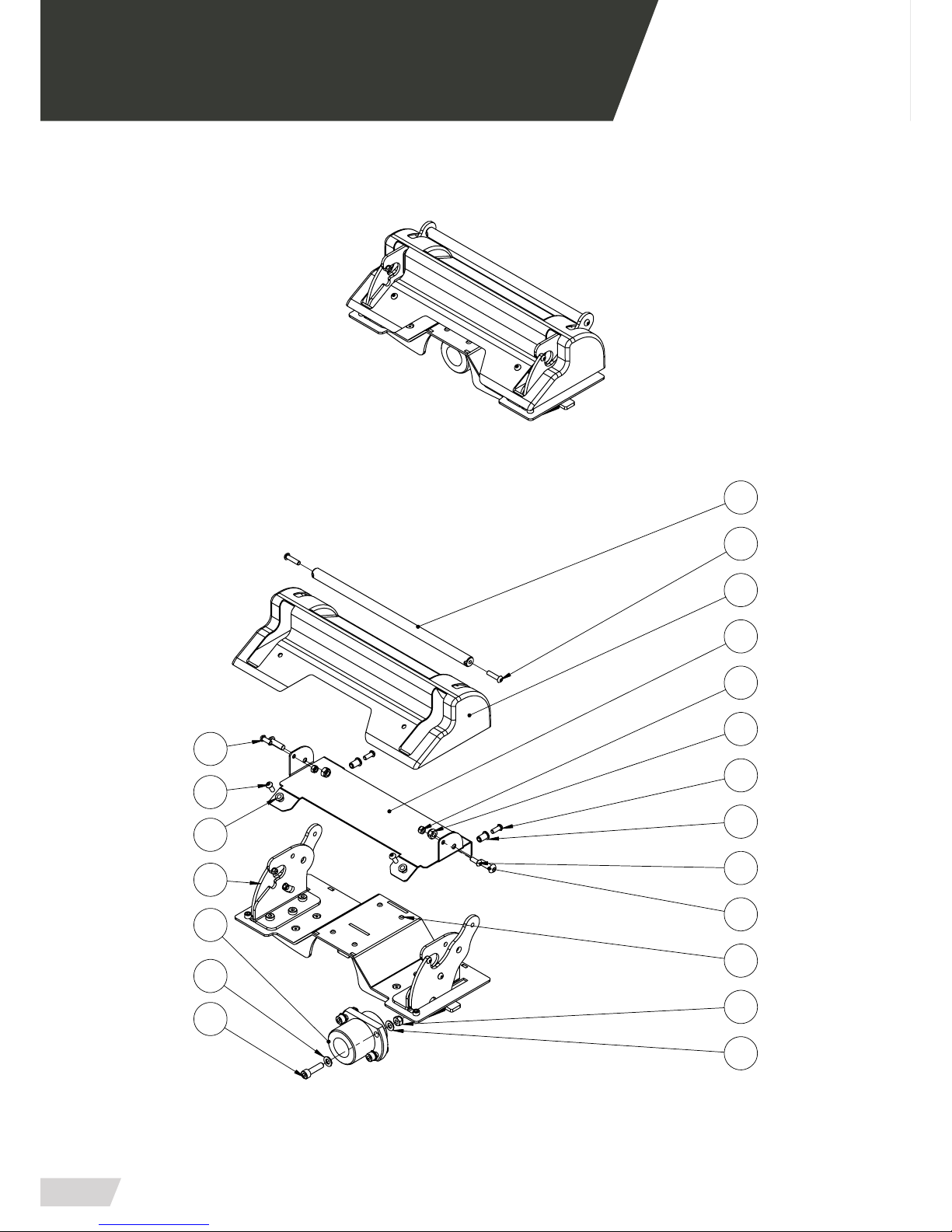
04.6 Base platform set PB-440/5 · PB-440/2
9
5
2
4
8
7
04 MOUNTING AND COMPONENTS
Page 35

USER MANUAL // ELEVATOR PB-440
Review 01/19
35
04.7 Bill of materials BASE PLATFORM SET PB-440/5 & PB-440/2
NUM. ELEMENT CODE - DESCRIPTION UNITS
06.2 PB4400-03000 - CONJUNT CARRO ELEVADOR 1
06.4 PB4400-00180 CILINDRE ELECTRIC MOTOR 1
06.5 PB4400-00180 CILINDRE ELECTRIC VASTEG 1
06.7 PB4100-00391 - EIX GIR SOPORT FIXADOR 1
06.8 31201081 ARANDELA D-125 M8 CINC 1
06.9 31305081 TUERCA D-985 M-8 CINC 1
04 MOUNTING AND COMPONENTS
Page 36
USER MANUAL // ELEVATOR PB-440
Review 01/19
36
04 MOUNTING AND COMPONENTS
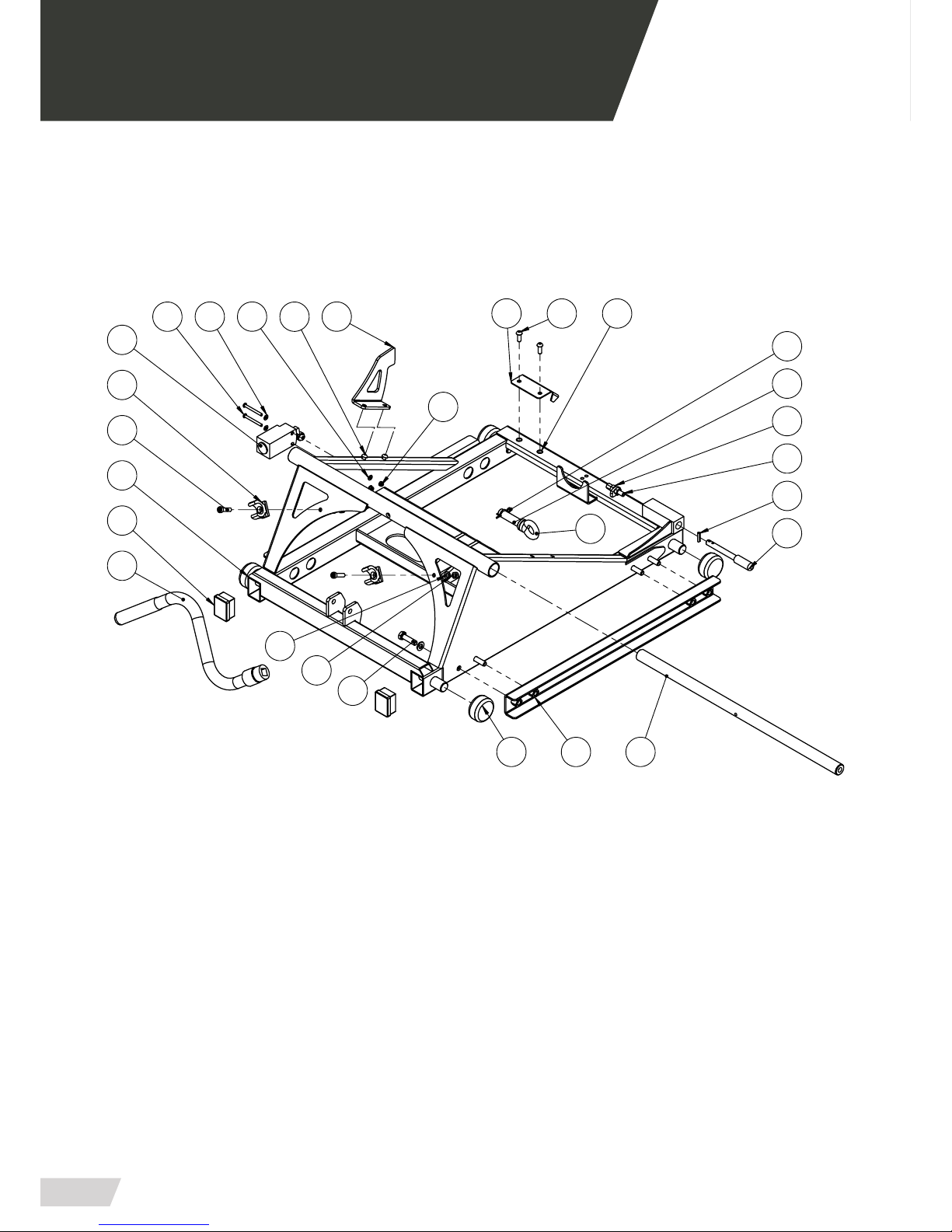
04.8 lift truck set PB-440/5 · PB-440/2
23
17
26
16
18
11
7
4
28
5
82
9
1
13
3
24
21
15
14
19
10
22
251325
27
6
Page 37

USER MANUAL // ELEVATOR PB-440
Review 01/19
37
04 MOUNTING AND COMPONENTS
04.9 Bill of materials LIFT TRUCK PB-440/5 & PB-440/2
NUM. ELEMENT CODE - DESCRIPTION UNITS
08.1 PB4400-03012 - SUBCONJUNT CARRO ELEVADOr 1
08.2 PB4100-03212 - SUBCONJUNT SUFRIDERA CARRO 2
08.3 PB4100-03110 - RODA NYLON 4
08.4 PB4400-03072 - DETECTOR INCLINACIO 1
08.5 PB4100-00291 - VALDA FIXACIO 1
08.6 PB4400-00421 - EIX GIR ACTUADOR 1
08.7 PB4400-03080 - PATI CADENA CARRO 1
08.8 VAR diam20A482 - EJE VARILLA CALIBRADA DIAM 20 A 482 1
08.9 TAPPLA-40x30 - TAPON PLASTICO INTERIOR 40x30 2
08.10 0853022 - BRIDA SUBJECCIO TUBS DIAM.20-22 2
08.11 83160006 - MICRO TIPUS CROUZET 1
08.12 ACTUADOR FINAL DE CARRERA 1
08.13 PB4400-00582 - MANIVELA ELEVADOR 1
08.17 PASA4x18N - PASADORT ELASTICO D-1481 4x18 NEGRO 1
08.27 PB4400-00590 - CLIP SUBJECCIO ACTUADOR 1
Page 38
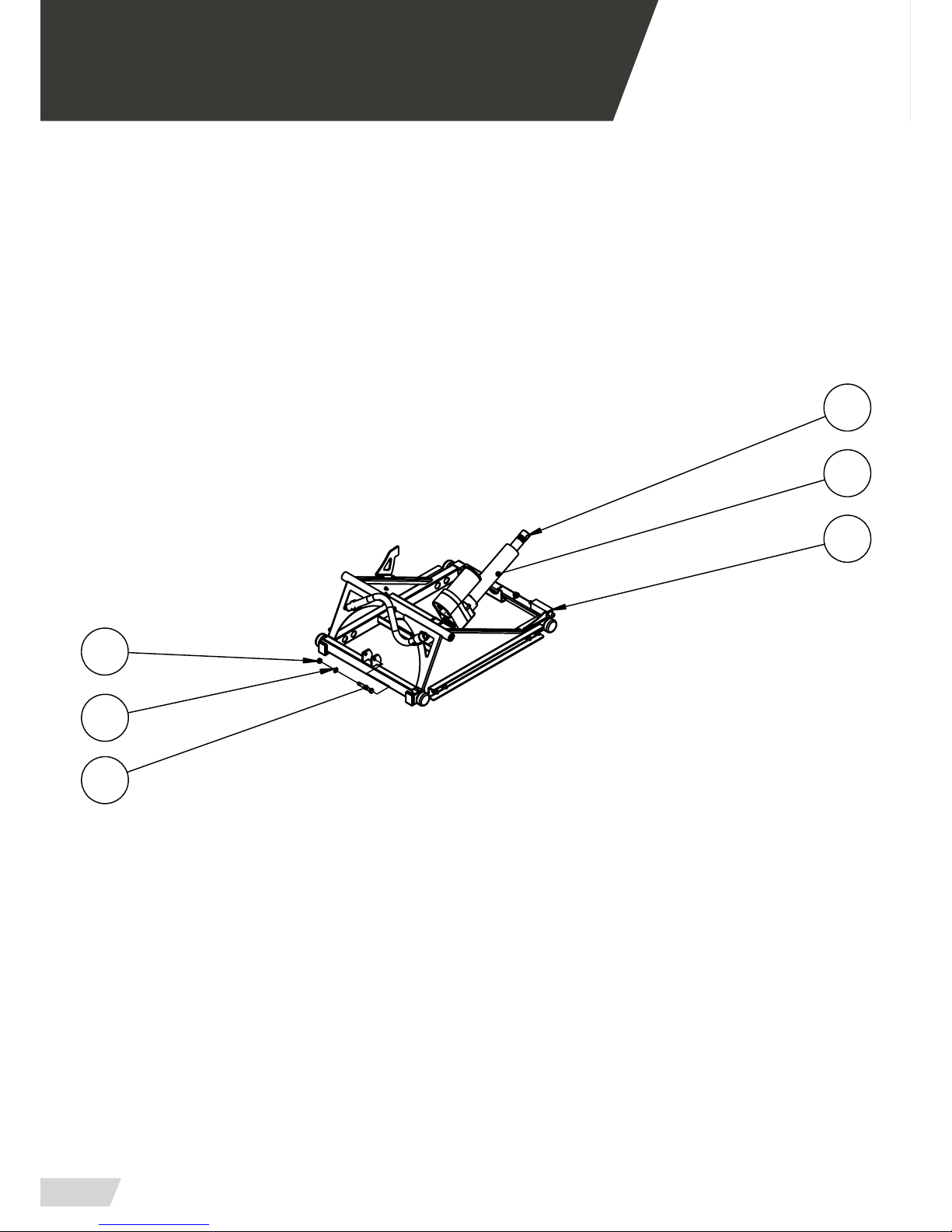
USER MANUAL // ELEVATOR PB-440
Review 01/19
38
04 MOUNTING AND COMPONENTS
04.10 Elevator guide set PB-440/5 · PB-440/2
6
10
11
3
Page 39

USER MANUAL // ELEVATOR PB-440
Review 01/19
39
04 MOUNTING AND COMPONENTS
04.11 Bill of materials ELEVATOR GUIDE SET PB-440/5 & PB-440/2
NUM. ELEMENT CODE - DESCRIPTION UNITS
10.3 PB4400-02000 - CONJUNT GUIA ELEVADOR 1
10.6 PB4400-00310 - CADENA PORTACABLES
(UNIFLEX 0345.030.020 KR38)
1
10.10 3110806201 - TORNILLO D-7991 M6x20 CINCADO 2
10.11 3110806101 - TORNILLO D-7991 M6x10 CINCADO 2
Page 40
USER MANUAL // ELEVATOR PB-440
Review 01/19
40
04 MOUNTING AND COMPONENTS
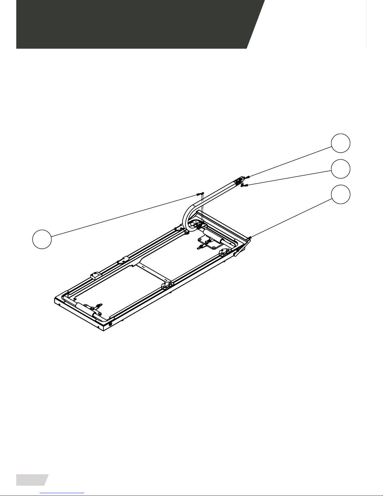
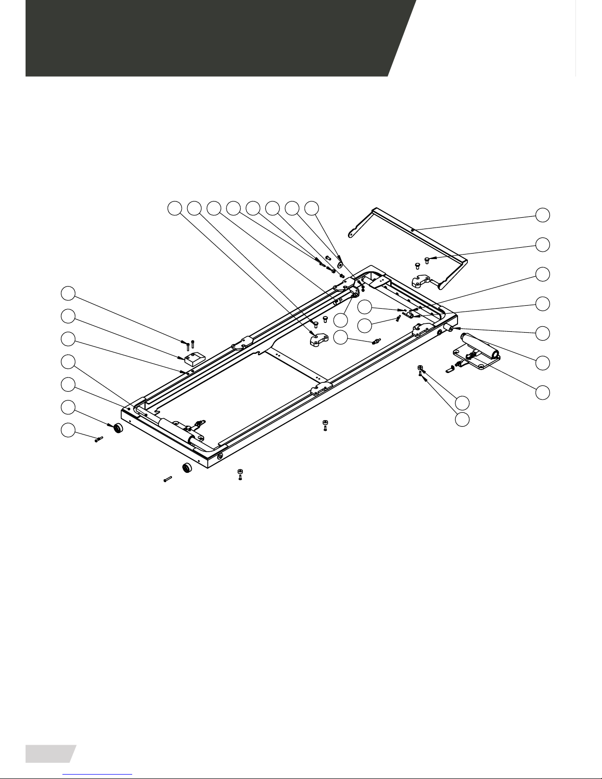
04.12 Elevator guide PB-440/5 · PB-440/2
17
5
16
6
104
19
9
17
23
2
8
6
11
7
1
12
14
18
20
22
3
24
25
21
26
14
2
Page 41

USER MANUAL // ELEVATOR PB-440
Review 01/19
41
04 MOUNTING AND COMPONENTS
04.13 Bill of materials ELEVATOR GUIDE PB-440/5 & PB-440/2
NUM. ELEMENT CODE - DESCRIPTION UNITS
12.1 PB4400-02012 - SUBCONJUNT GUIA ELEVADOR 1
12.2 PB4100-02251 - TORRIO FIXADOR LATERAL 2
12.3 PB4100-02332 - SUBCONJUNT ACTUADOR MOVIMENT
LATERAL
1
12.4 TEM-6(20X20) - TOPE EGAÑA M-6 (TS20-25) 2
12.5 PB4100-02271 - FIXACIO LONGITUDINAL 2
12.6 PB4100-02160 - GUIA MOVIMENT LATERAL 2
12.7 CD750RUEGUIA - RUEDA NYLON DIAM.40 4
12.8 PB4100-02240 - DISC APOIO MOVIMENT LATERAL 6
12.9 PB4400-06002 - PEDAL MOVIMENT LATERAL 1
12.11 PB4100-01000 - CONJUNT PLETINA COLLADA 2
12.12 PB4400-02090 - PATI GUIA MICRO SEGURETAT 1
12.13 PB4400-04190 - CLIP ALUMINI Ø4.8 AC-3 2
12.23 3180106282 - PASADOR NORMAL D-6325 H6 D6x28 1
Page 42

Page 43
USER MANUAL // ELEVATOR PB-440
Review 01/19
43
05 ELECTRICAL CIRCUIT DIAGRAM
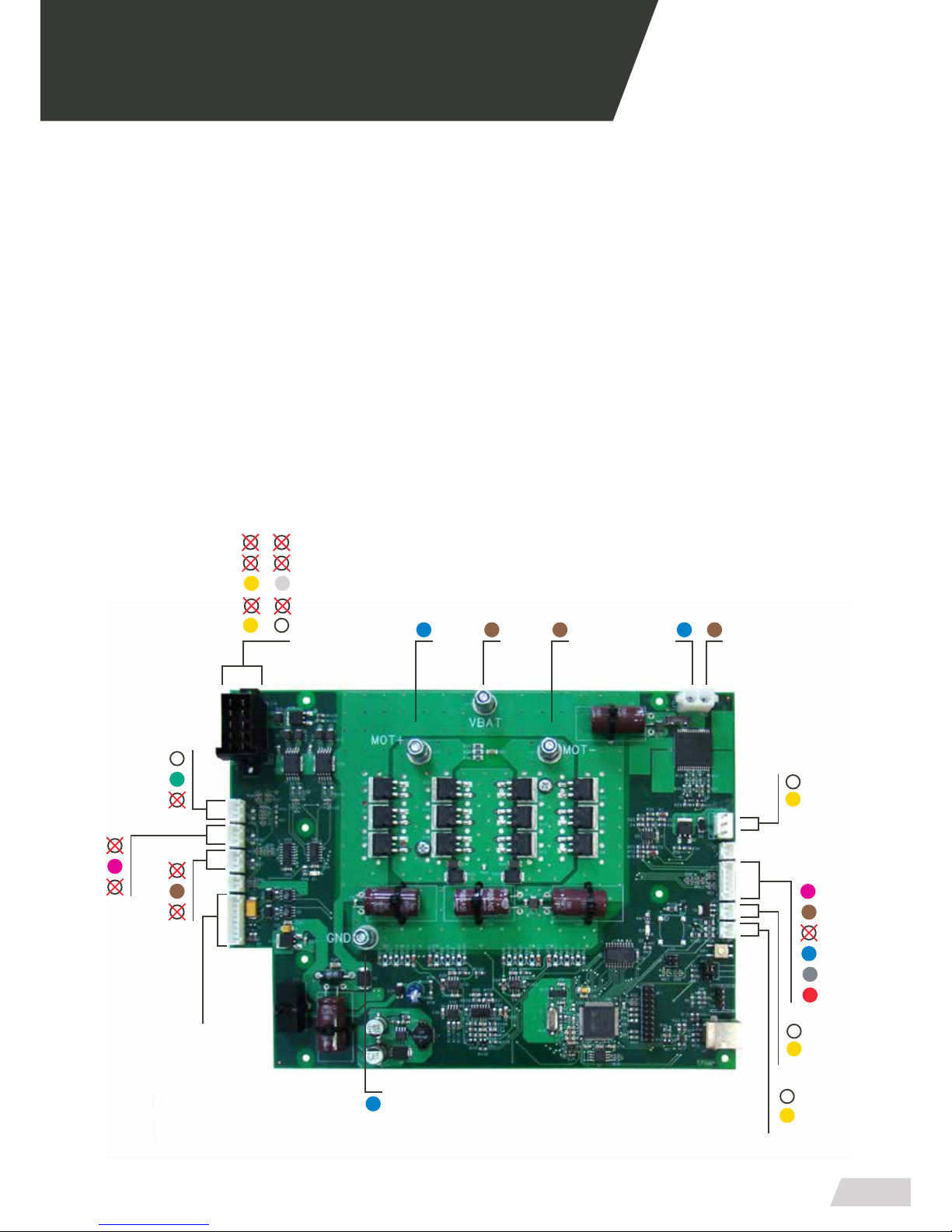
05.1 Printed circuit board
Components
1. Loading position (Control command) 14. Tilt switch 2
2. Micro-sensor (Loading handle) 15. Tilt switch 1
3. Zero position (Control command) 16. Micro-switch for loading position (common)
4. Micro-sensor (Unloading handle) 17. Micro-switch for loading position
5. Emergency stop 18. Linear Actuator A1 (common)
6. Subsequent signals (common) 19. Linear Actuator A1
7. Mains connection 12v + 20. Motor
8. Mains connection 12v - 21. Motor (common)
9. Trendelemburg declive (Control command) 22. LED (common)
10. Trendelemburg proclive (Control command) 23. LED
11. Upload platform (Control command) 24. Buzzer (siren) (common)
12. Download platform (Control command) 25. Buzzer (siren)
13. Common (Control command) 26. Encoder
20 07 21 1918
06
07
09
10
11
12
13
08
16
17
14
15
03
04
01
02
* Polarity inverts depending on the movement that it’s running.
22
25
23
24
26
Page 44
USER MANUAL // ELEVATOR PB-440
Review 01/19
44
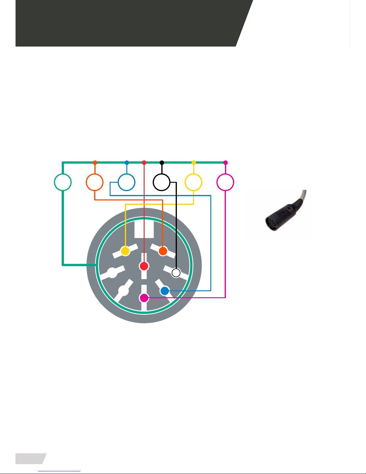
05.2 PIN conector Hand control
Female connector diagram
SW6 SW5 SW4 SW3 SW2 SW1
9 (common)
1 7
5
84
3
9
2
FRONTAL VIEW
CONECTOR DIN
- FEMALE -
05 ELECTRICAL CIRCUIT DIAGRAM
Page 45
USER MANUAL // ELEVATOR PB-440
Review 01/19
45
SW6
9 (common)
7 1
3
48
5
9
2
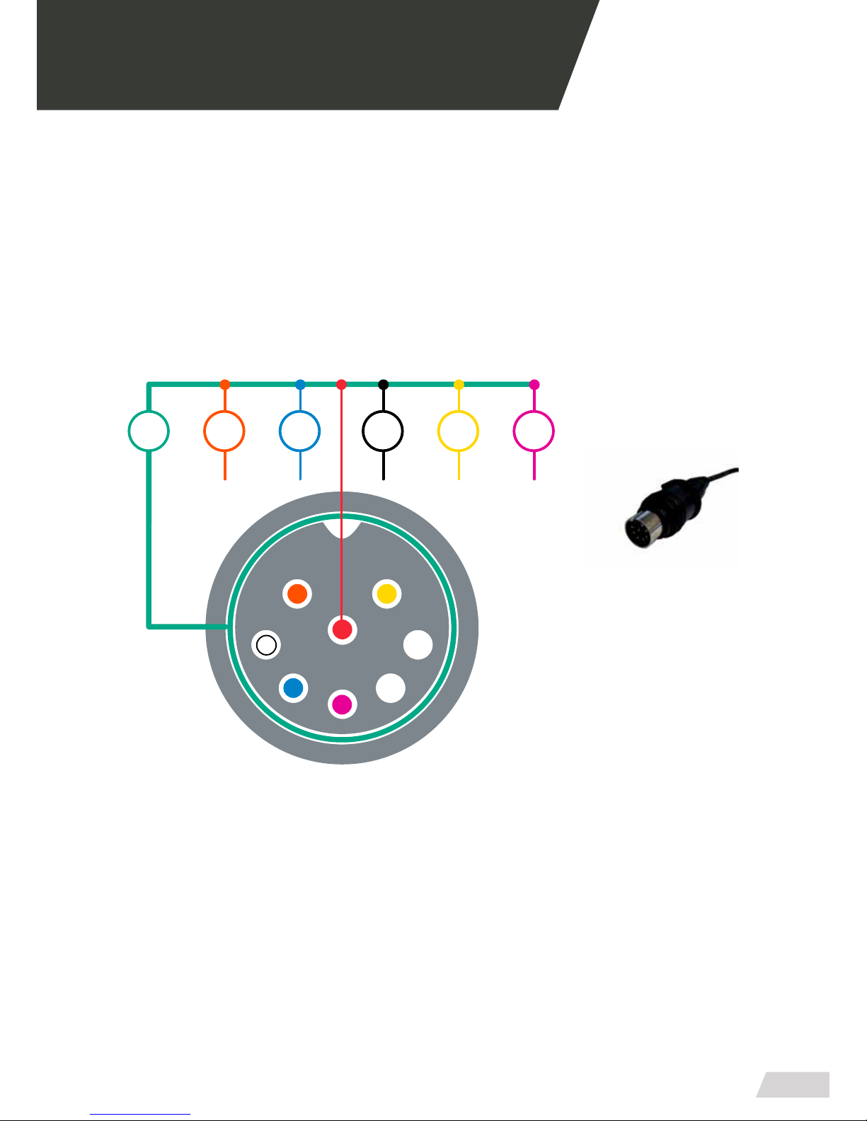
FRONTAL VIEW
CONECTOR DIN
- MALE -
SW5 SW4 SW3 SW2 SW1
7 8 5 1 2
05 ELECTRICAL CIRCUIT DIAGRAM
Male connector diagram
Page 46
USER MANUAL // ELEVATOR PB-440
Review 01/19
46
06 GENERAL MAINTENANCE
CLEANING
Keeping the equipment cleaned is essential to ensure a good use and durability of the set. It is necessary
to make a periodical thorough cleaning, especially in
areas exposed to dirt that could suer damages, such
as gears, connectors, switches, etc. Do not use high-pressure cleaning, they can damage the electrical
elements.
CONTROLS AND SELECTORS
Due to a heavy and continued use of the moving parts,
such as controls and selectors, check them periodically for a proper functioning. There may be failures on
micro-switches and cabling; examine the xations and
electric or mechanical connections that could exist.
GREASE
Generally, every moving part should be greased. Our
products leave the factory completely greased and lubricated, however, it is possible that with the time and
usage of the product the elements degrease, either by
loss of lubrication or by dirt. Clean and grease periodically the aected zones according to the manufacturer’s specications.
Verify that there are no loose, worn, or missing parts.
Examine periodically every moving element to ensure
that they are all tighten.
Do not grease the platform guide because of its sliding
dry system.
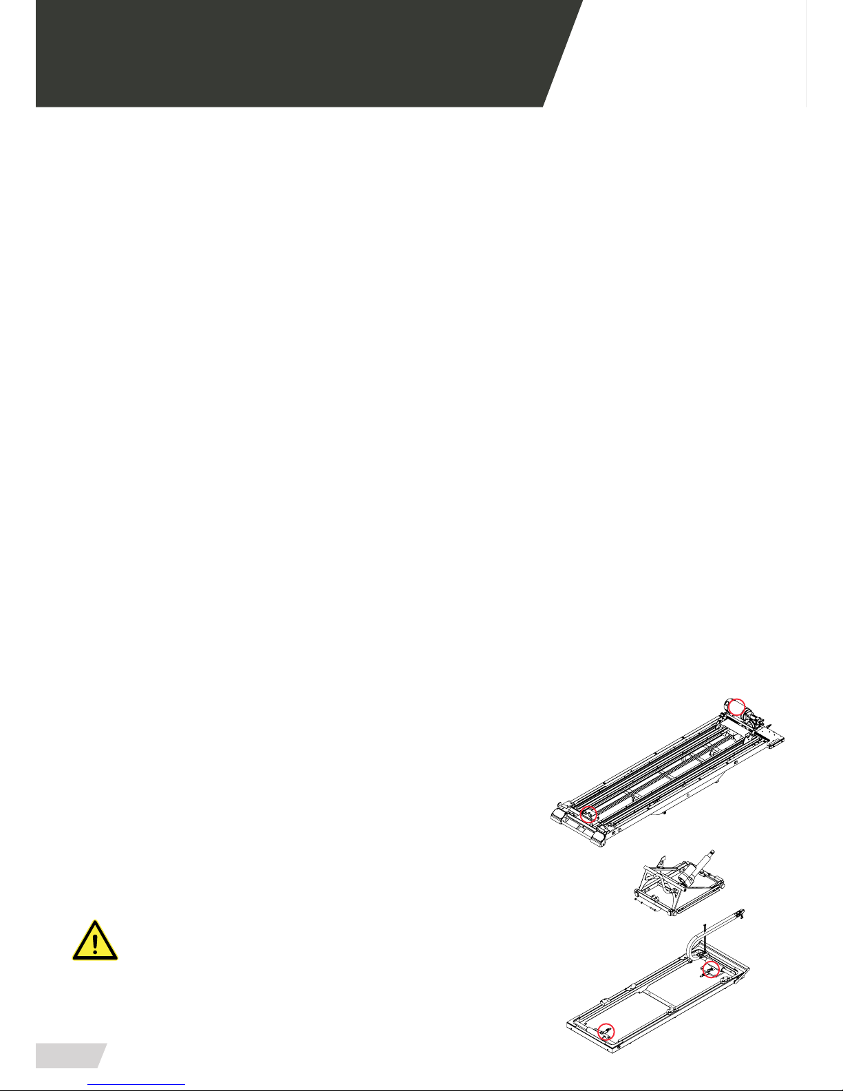
WARNING: Do not lubricate the bench once connected
to the electricity network.
WEAR AREAS
Regularly examining the system’s components to
check if they are wearing out is a preventive measure
that can reduce breakdowns. Verify possible lubricate
leaks, grooves or bearings in poor condition.
MECHANICAL FIXING
Generally we call mechanical xing to the components
that are used to attach joint products, mainly screws
and derivatives.
In some conditions of use, due to vibrations or impacts,
many elements could lose their tightening torque or
hold properties.
Periodically examine that no elements are unleashed,
especially in the moving parts of the set. Take into account and always respect the recommended tightening torques.
REPLACEMENT OF COMPONENTS
This instruction manual doesn’t include procedures for
every part. The service sta typically substitutes cables,
commutators and certain mechanical parts without
any step by step procedure.
The qualied service personnel must contact our commercial department for information about ordering
pieces and its installation.
MAKE SURE TO KEEP THESE AREAS FREE OF WATER AND HUMIDITY.
TAKE SPECIAL CARE NOT TO WET THEM WHILE WASHING THE SET.
Page 47

USER MANUAL // ELEVATOR PB-440
Review 01/19
47
07 LEGAL NOTICES
This document may contain technical inaccuracies or
typographical errors.
Changes are periodically added to the information
herein; these changes will be incorporated in new editions of the publication.
Promeba, S.L. reserves the right to make, if considered
appropiate, any modication or improvement to the
products described in this publication.
Promeba, S.L. may have patents or patent applications
which address themes described in this document. The
possession of this document does not entitle no license to these patents.
The information contained in this document does not
aect or change the specications or product warranties of Promeba, S.L.
No part of this document shall operate as express or
implied license or compensation under the intellectual
property rights of Promeba, S.L. or third party.
All the information contained in this document has
been obtained in specic environments and it is presented as an illustration. The results obtained in other
operating environments may vary.
Promeba, S.L. may use or distribute the information
that the client provides in whatever way they see t,
without incurring any obligation with the client.
Page 48

USER MANUAL // ELEVATOR PB-440
Review 01/19
48
08 PRODUCT WARRANTY
Promeba, S.L. warrants that their products have suc-
cessfully passed all quality controls, both functional
and material. The warranty period is 2 years from the
date of purchase.
This warranty will only be granted when the original
invoice or sales receipt (indicating the date of purchase, model and the distributor’s name) is presented together with the defective product during the warranty
period. Promeba, S.L. reserves the right to not oer
the free warranty service if the indicated documents
are not presented or if the information provided by the
consumer is false, incomplete or illegible.
1. This warranty shall not apply if the model’s name or the
serial number has been altered, removed, disappeared or
is illegible.
2. This warranty does not cover transportation costs or
risks associated with the transport of the product to and
from Promeba, S.L.
3. This warranty does not cover any of the following cases:
A. Regular maintenance and reparation or replacement
of parts from the normal wear and use.
B. Consumables (components that may need periodic replacements during the product’s life, such as non-rechargeable batteries, bulbs, etc.)
C. Damages or defects resulting from the use, operation
or improper treatment of the product and not caused by
a normal use of it.
D. Damages arising from:
i. Improper use, including:
- Treatment resulting in damages or physical changes,
surface or appearance changes of the product.
- Installation, use or storage of the product in a manner
inconsistent with the instructions described by Promeba,
S.L.
- Product maintenance in a manner inconsistent with the
instructions of Promeba, S.L. for a proper maintenance.
- Installation or product use in a manner inconsistent with
the technical or security standards of the country where it
is used or installed.
ii. Use of components not supplied with the product
or incorrect installation of accessory parts previously
untested.
iii. States or defects of the system in which the product
is incorporated with the exception of other products of
Promeba, S.L. designed for its use with the product.
iv. Product use with accessories, peripheral units and
other products of a type, condition or standard not established by Promeba, S.L.
v. The manufacturer or distributor shall be solely responsible for determining the sending of parts for its reparation or the replacement of the product in its entirety. In no circumstance shall operators be send to such
reparation or product replacement.
Except in the cases mentioned above, Promeba, S.L.
shall not give any guarantees in relation to the product, operation, accuracy, reliability or adaptability for
an equipment logical purpose or any other type. If this
exception is not lawful or established in the law, Pro-
meba, S.L. shall limit or exclude their guarantees only
to the extent that the applicable law permits it.
The only obligation of Promeba, S.L. regarding this
warranty is to repair or replace the parts subjected to
the terms and condition of this warranty.
Promeba, S.L. is not liable for loss or damages to products, this warranty or others, including economic loss
or not assessable damage; the price paid for the product; loss of prots, incomes, information, usufruct or
use of the product or associated products or indirect
loss or damage, accidental or critical.
This clause refers to whether the loss or damage is due
to a product deterioration or inoperability associated
to defects or unavailability of Promeba, S.L. that caused a downtime, user’s time loss or a business interruption.
In the cases in which the law prohibits or limits these
responsibility exclusions, Promeba, S.L. shall exclude
or limit their responsibility only to the extent that the
law allows. For example, many countries forbid the exclusion or limitation of damages caused by negligence,
gross negligence, wilful misconduct, fraud and similar
acts. The responsibility of Promeba, S.L. in this warranty shall not exceed, in any case, the price paid for the
product, but if the applicable law permits only responsibility limitations of major responsibilities, these shall
be applied.
Page 49

Page 50

ER-0687/1998
PROMEBA, S.L.
Ctra C-16 Km 59.5 · 08650 Sallent (Barcelona) · SPAIN
T. 93 837 12 00 · Fax 93 820 61 08
[email protected] · www.promeba.com
All rights reserved. Variations can be done whitout notice.
Promeba, S.L. is to be considered not responsible for damages caused by the lack or the wrongness
of the information here mentioned.
 Loading...