

Page 1
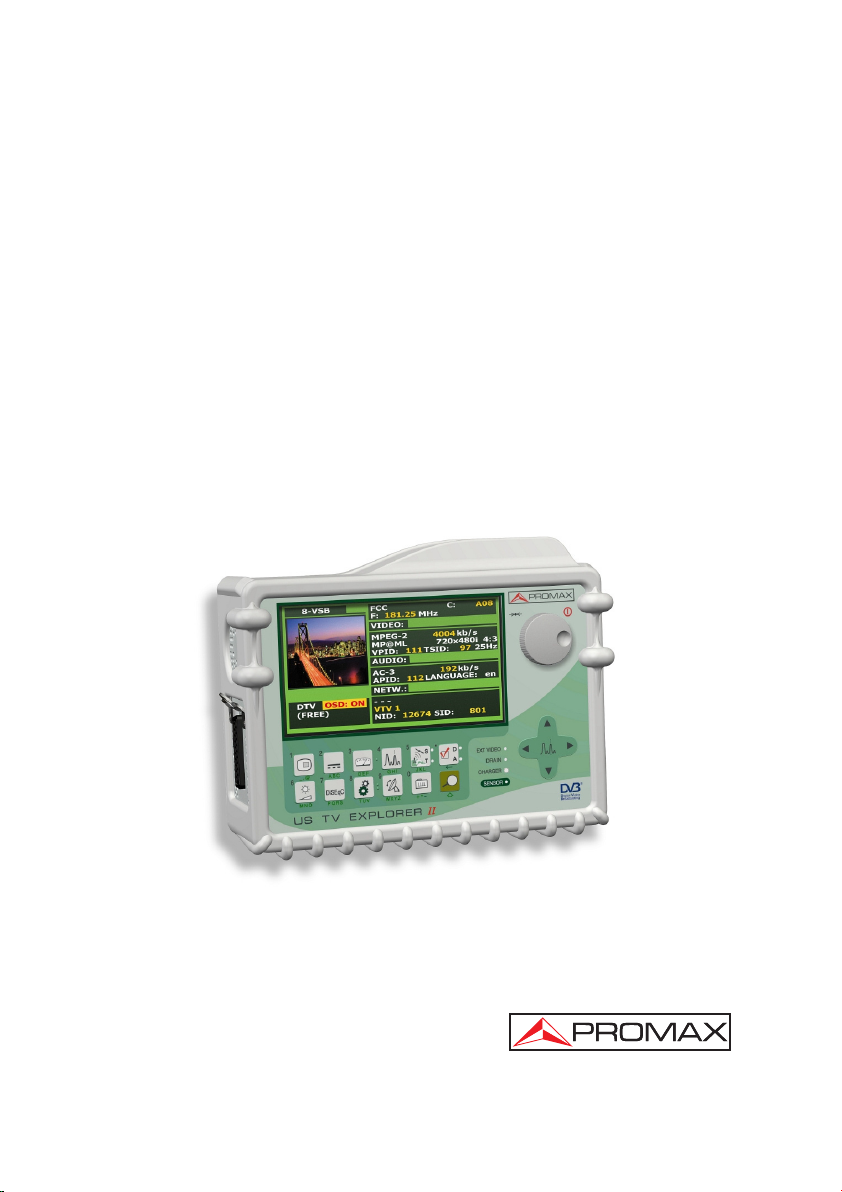
US TV EXPLORER II
EXPLORADOR US DE TV
EXPLORATEUR US DE TV
- 0 MI1526 -
Page 2

Page 3

SAFETY NOTES
Read the user’s manual before using the equipment, mainly " SAFETY RULES "
paragraph.
The symbol
manual may also appear as a Caution or Warning symbol.
Warning and Caution statements may appear in this manual to avoid injury
hazard or damage to this product or other property.
on the equipment means "SEE USER’S MANUAL". In this
NOTAS SOBRE SEGURIDAD
Antes de manipular el equipo leer el manual de instrucciones y muy
especialmente el apartado PRESCRIPCIONES DE SEGURIDAD.
El símbolo
INSTRUCCIONES". En este manual puede aparecer también como símbolo de
advertencia o precaución.
Recuadros de ADVERTENCIAS Y PRECAUCIONES pueden aparecer a lo largo de
este manual para evitar riesgos de accidentes a personas o daños al equipo u
otras propiedades.
sobre el equipo significa "CONSULTAR EL MANUAL DE
REMARQUES À PROPOS DE LA SECURITE
Avant de manipuler l'appareil, lire le manuel d'utilisation et plus particulièrement le
paragraphe "PRESCRIPTIONS DE SECURITE".
Le symbole
Dans ce manuel, il peut également apparaître comme symbole d'avertissement ou de
précaution.
Des encadrés AVERTISSEMENTS ET PRECAUTIONS peuvent apparaître dans ce
manuel pour éviter des risques d'accidents affectant des personnes ou des dommages
à l'appareil ou à d'autres biens.
sur l'appareil signifie "CONSULTER LE MANUEL D'UTILISATION".
Page 4

Page 5

CONTENTS
SUMARIO
SOMMAIRE
English manual ............................................................
Manual español.............................................................
Manuel français ..............................................................
English
Français
Page 6

Page 7

USER’S MANUAL. US TV EXPLORER II
TABLE OF CONTENTS
1 GENERAL.................................................................................................................. 1
1.1 Description .......................................................................................................... 1
1.2 Specifications......................................................................................................4
SAFETY RULES...................................................................................................... 11
2
2.1 General safety rules..........................................................................................11
2.2 Descriptive Examples of Over-Voltage Categories...........................................13
INSTALLATION .......................................................................................................15
3
3.1 Power Supply....................................................................................................15
3.1.1 Operation using the External DC Charger ..................................................15
3.1.2 Operation using the Battery ........................................................................15
3.1.2.1 Battery Charging ...............................................................................16
3.2 Installation and Start-up .................................................................................... 16
QUICK USER GUIDE..............................................................................................17
4
OPERATING INSTRUCTIONS................................................................................ 21
5
5.1 Description of the Controls and Elements .........................................................21
5.2 Adjustment of Volume and Monitor Parameters................................................30
5.3 Selecting the Operation Mode: TV / Spectrum Analyzer / Measurements........ 31
5.4 Channel Tuning / Frequency Tuning................................................................. 31
5.5 Automatic Transmission Search........................................................................32
5.6 Selecting the measurement configuration: Analogue/ Digital signal.................32
5.7 External Units Power Supply .............................................................................32
5.8 Automatic signal identification function (AUTO ID) ........................................... 33
5.9 Channel plans ................................................................................................... 34
5.10 Acquisition function (DATALOGGER) ................................................................ 36
5.10.1 DATALOGGER for Attenuation and IF SAT tests.......................................37
5.11 Verification of distribution networks....................................................................39
5.12 Spectrum exploration function (EXPLORER)....................................................41
5.13 Measurements configuration .............................................................................42
5.13.1 ITU-T J.83/B (QAM Annex-B) Digital Channel Configuration .....................42
5.13.2 DVB-C (QAM) Digital Channel Configuration .............................................43
5.13.3 ATSC (8-VSB) Digital Channel Configuration.............................................43
5.13.4 DVB-S/S2 (QPSK/8PSK) Digital Channel Configuration ............................44
5.13.5 DSS (QPSK) Digital Channel Configuration ...............................................46
5.14 Selecting the Measurements .............................................................................47
5.14.1 Analogue TV: Measuring the Video Carrier Level....................................... 49
5.14.2 Analogue TV: Measuring the Video / Audio ratio (V/A)...............................51
5.14.3 Analogue TV: Measuring the FM deviation................................................. 51
5.14.4 Analogue FM: Measuring the Level and demodulating signal .................... 52
5.14.5 Analogue/Digital TV: Measuring the Carrier / Noise ratio (C/N).................. 52
English
Page 8

USER’S MANUAL. US TV EXPLORER II
5.14.6 Digital TV: Measuring the Power of Digital Channels .................................54
5.14.7 Digital TV: Measuring BER .........................................................................55
5.14.7.1 ITU-T J.83/B signals .........................................................................56
5.14.7.2 DVB-C signals................................................................................... 57
5.14.7.3 ATSC signals .................................................................................... 58
5.14.7.4 DVB-S/S2 and DSS signals..............................................................60
5.14.8 Digital TV: Measuring MER......................................................................... 63
5.15
Constellation Diagram .......................................................................................64
5.15.1 ITU-T J.83/B (QAM-Annex B) signal...........................................................65
5.15.2 DVB-C (QAM) signal...................................................................................66
5.15.3 DVB-S/S2 (QPSK/8PSK) signal.................................................................. 67
5.15.3.1 Zoom, scroll and erasing functions ................................................... 68
5.16 Spectrum Analyzer ............................................................................................69
5.16.1 Markers .......................................................................................................70
5.17 Screen capture ..................................................................................................71
5.17.1 Recall screen ..............................................................................................71
5.17.2 Delete capture............................................................................................. 72
5.18 TV Operating Mode........................................................................................... 72
5.18.1 Recording and playing video streams.........................................................76
5.19 Antenna Alignment Function .............................................................................76
5.20 DiSEqC Command Generator........................................................................... 77
5.21 SATCR function.................................................................................................79
5.22 Using the alphanumeric keyboard.....................................................................79
DESCRIPTION OF THE INPUTS AND OUTPUTS.................................................81
6
6.1 RF input .............................................................................................................81
6.2 USB port ............................................................................................................81
6.3 Scart (DIN EN 50049) ....................................................................................... 81
6.4 RCA adapter......................................................................................................82
MAINTENANCE....................................................................................................... 83
7
7.1 Considerations about the Screen. .....................................................................83
7.2 Cleaning Recommendations .............................................................................83
Page 9

USER’S MANUAL. US TV EXPLORER II
US TV EXPLORER II
1
1 GENERAL
1.1 Description
The television explorer US TV EXPLORER II represents an evolutionary step with
respect to the traditional field strength meters. The continuous PROMAX innovation
process in the sector of field strength meter yields an instrument that changes the way
to take and understand television signals measurements.
This equipment incorporates important advances in the functional aspects as
well as in the ergonomics to allow the installers to make their work with maximum
comfort and speed. Simultaneously the instrument is reliable for any possible problem
at the input signal, at the distribution components or the receiver equipment.
The US TV EXPLORER II has been designed to satisfy all the necessities of
measurement during the transition from the analogue transmissions to digital in
terrestrial, satellites and cable systems. Allowing measurements of analogue signals
as well as digital ones. When pressing the auto identification key, it searches and
identifies the signal under test. First it recognizes whether the signal is an analogue
channel or a digital one. When the signal is digital (ATSC, DVB-S/S2,ITU-T J.83/B,
DVB-C, DSS), it analyses for each modulation type 8-VSB / QAM
ANNEX-B / QPSK / 8PSK all the associated parameters: symbol rate, code rate, etc.
and determines the value of the signals under test.
The range of frequencies covered makes this instrument an excellent tool for FM
radio, terrestrial TV, mobile TV, satellite TV and cable TV (where the subband tuning
margin, from 5 to 45 MHz, enables the user to carry out tests on the return channel).
The US TV EXPLORER II adapts itself to the characteristic parameters of the
standard and to the correct automatic system in order to obtain in all the cases an
accurate measuring of the input signal level. It accepts the NTSC TV system and allows
the user to work directly with digital TV signals decoding them, so that the television
image may be viewed, and directly measuring the power, carrier/noise ratio (C/N), the
bit error rate (BER) and the modulation error ratio (MER), as well for ATSC (8-VSB) as
DVB-S (QPSK), DVB-S2 (8PSK), DSS (QPSK), DBV-C (QAM Annex-A) and ITU-T
J.83/B (QAM Annex-B) signals. This instrument allows to obtain besides a graphical
representation of the Constellation Diagram for DVB-S/S2 (QPSK/8PSK),
DVB-C(QAM) and ITU-T J.83/B (64/256-QAM) signals.
ANNEX-A / QAM
English
1
Trademark of the DVB - Digital Video Broadcasting Project (4914).
01/2008 Page 1
Page 10

USER’S MANUAL. US TV EXPLORER II
Being a multistandard instrument, it can be efficiently used in any country of the
world.
Includes a symbol-based keyboard that allows the direct access to the various
functions that are displayed simultaneously on screen.
The US TV EXPLORER II makes a dynamic exploration of the spectrum,
detecting all the channels in the explored band, this applies for the terrestrial and the
satellite television bands. The meter locates all the channels in the spectrum with no
need of any previous information about the number of channels, the type of signals
transmitted or their characteristics. With the data collected after each exploration, it
creates a register that contains tables of channels that can be independent for each
system or installation. At any time, the measurement sessions using only the
pretuned channels can be repeated. In this way it is possible to optimize the
measurement process.
Shown on the frontal panel is the type of measurement that is being carried
(Terrestrial-Satellite/Analogue-Digital) and the data are presented on a hi-res
transflective 6.5" graphic TFT display with panoramical format. The equipment
incorporates a light sensor that activates the contrast and luminosity of the display
according to the environmental conditions.
The US TV EXPLORER II is an ideal size to hold with a hand. The instrument
can be held to the body with the carrying bag or transport belt, which at the same time
protects it from the rain. Because it is designed for outdoor use, it includes an anti-
shock protector that completely covers the instrument, and optionally can be supplied
with a strong transport case. As well, the front panel does not have any keys nor gaps
to avoid accidental water ingress.
The US TV EXPLORER II is designed to integrate measurements that require
different operating configurations. In this way it incorporates a specific function to
facilitate the alignment of antennas. When activating the alignment function the
instrument is set automatically to offer a fast spectrum sweep and a high sensitivity
graphical bar that allows fine adjust for the maximum signal. In addition it includes a
module for the powering of LNBs and the commands for the programming of DiSEqC
1.2 and SatCR devices.
The US TV EXPLORER II can be updated to new software versions that extend
the available functions in the future. That means it can incorporate new benefits without
additional cost. For example, in the test of satellite signals distribution networks,
used in combination with an IF generator to carry out an easy verification of the
installations before commissioning.
The spectrum analyzer features with high accuracy, resolution, sensitivity and
sweep speed allows the instrument to be very useful for applications as the antenna
installation or the detection of complex impulsional noise events. It presents an
innovative control system based on four arrows, that makes the use of the spectrum
analyser very intuitive. The arrows allow adjusting the reference level by steps of 5 or
10dB and the frequency margin span on screen.
Page 2 01/2008
Page 11

USER’S MANUAL. US TV EXPLORER II
To enhance its convenience of use, it includes memories to store automatically
the different data acquisitions, i.e.: acquisition name, test points, frequency, channel
plan, etc.,. Moreover, the DATALOGGER function makes it much easier to test systems
in which a large number of measurements have to be made, and enables further
processing of all the information acquired using a computer system. The equipment is
able to generate automatic measurement reports and to update itself through Internet
by means of PkTools provided software.
Also, this meter incorporates a DiSEqC
2
command generator and permits to
supply different voltages to the external unit (5 V / 13 V / 15 V / 18 V / 24 V) and
includes a SCART-RCA adapter, for audio/video input/output.
The US TV EXPLORER II is powered by rechargeable battery or connected to
the mains through the supplied external DC power charger.
It incorporates a USB port, which enables the communication with a PC and to
download dataloggers and channel plans.
This instrument due to its extreme-compact design, technical specifications and
low cost becomes the industry standard for the installer.
English
2
TM
DiSEqC
is a trademark of EUTELSAT.
01/2008 Page 3
Page 12

USER’S MANUAL. US TV EXPLORER II
1.2 Specifications
CONFIGURATION FOR MEASURING LEVEL AND POWER
TUNING Digital frequency synthesis. Continuous tuning from
Tuning modes Channel or frequency (IF or downlink at satellite
Channel plan configurable on demand.
Resolution 5-1000 MHz: 50 kHz
Automatic search (Explorer) Threshold level selectable.
Signal identification Analogue and digital. Automatic.
RF INPUT
Impedance 75 Ω.
Connector Universal, with BNC or F adapter.
Maximum signal 130 dBµV.
Maximum input voltage
DC to 100 Hz 50 Vrms (powered by the AL-103 power charger).
30 Vrms (not powered by the AL-103 power charger).
5 MHz to 2150 MHz 130 dBµV.
DIGITAL SIGNALS MEASUREMENT
POWER RANGE
8-VSB: 45 dBµV to 100 dBµV.
QAM Annex-B/-A: 45 dBµV to 110 dBµV.
QPSK/8PSK: 44 dBµV to 114 dBµV.
DSS: 44 dBµV to 114 dBµV.
MEASUREMENTS
ATSC (8-VSB): Power, SER, VBER
Presentation: Numeric and level bar.
5 to 1000 MHz and from 950 to 2150 MHz.
band).
950-2150 MHz: < 200 kHz (span FULL-500-200-
100-50-32-16 MHz).
3
,
MER, C/N and noise margin.
3
The BER measurement shown by default (when PRN-23 BER option from Preferences menu is set to OFF)
yields an estimated value calculated using the MER measurement. In order to obtain a more accurate BER
measurement value, the PRN-23 BER option from Preferences menu must be set to ON and a PRN-23 signal
pattern must be used through the RF signal input [30].
If the input signal is like PRN-23 or a video signal, the BER and VBER measurement are considered as
acceptable when BER/VBER
taken as reference measurement.
Page 4 01/2008
≤
3*10E-6 and SER-ERR/s ≤ 2 being SER value the number of wrong packets
Page 13

USER’S MANUAL. US TV EXPLORER II
ITU-T J.83/B (QAM Annex-B): Power, BER, MER, C/N and noise margin.
Presentation: Numeric and level bar.
DVB-C (QAM Annex-A): Power, BER, MER, C/N and noise margin.
Presentation: Numeric and level bar.
DVB-S (QPSK): Power, CBER, VBER, MER, C/N and noise margin.
Presentation: Numeric and level bar.
DVB-S2 (QPSK/8PSK): Power, CBER, MER, C/N, PER and LBER.
Presentation: Numeric and level bar.
DSS (QPSK): Power, CBER, VBER, MER, C/N and noise margin.
Presentation: Numeric and level bar.
CONSTELLATION DIAGRAM
Type of signal DVB-S, DVB-S2 and QAM-B.
Presentation I-Q graph.
ATSC SIGNAL PARAMETERS
Code Rate 2/3
Spectral inversion Selectable: ON, OFF.
Symbol rate 10.762 Mb/s.
ITU-T J.83/B SIGNAL PARAMETERS
Demodulation 64/256 QAM.
Symbol rate 5057 to 5361 kbauds.
Roll-off (α) factor
of Nyquist filter 0.15.
Spectral inversion Selectable: ON, OFF.
DVB-C SIGNAL PARAMETERS
Demodulation 16/32/64/128/256 QAM.
Symbol rate 1000 to 7000 kbauds.
Roll-off (α) factor
of Nyquist filter 0.15.
Spectral inversion Selectable: ON, OFF.
DVB-S SIGNAL PARAMETERS
Symbol rate 2 to 45 Mbauds.
Roll-off (α) factor
of Nyquist filter 0.35.
Code Rate 1/2, 2/3, 3/4, 5/6, 7/8 and AUTO.
Spectral inversion Selectable: ON, OFF.
English
01/2008 Page 5
Page 14

USER’S MANUAL. US TV EXPLORER II
DVB-S2 SIGNAL PARAMETERS
Symbol rate (QPSK) 2 to 33 Mbauds.
Symbol rate (8PSK) 2 to 30 Mbauds.
Roll-off (α) factor
of Nyquist filter 0.35,0.25 and 0,35.
Code Rate (QPSK) 1/4, 1/3, 2/5, 1/2, 3/5, 2/3, 3/4, 4/5, 5/6, 8/9, 9/10 and AUTO.
Code Rate (8PSK) 3/5, 2/3, 3/4, 5/6, 8/9, 9/10 and AUTO.
Spectral inversion Selectable: ON, OFF
Pilots Presence indication.
DSS SIGNAL PARAMETERS
Symbol rate 20 Mbauds.
Roll-off (α) factor
of Nyquist filter 0.20.
Code Rate 1/2, 2/3, 6/7 and AUTO.
Spectral inversion Selectable: ON, OFF.
VIDEO
Format ATSC: MPEG-2 (MP@ML)
DVB: MPEG-2 (MP@ML).
Services decoding Service list and PIDs
ANALOGUE SIGNALS MEASUREMENT
LEVEL MEASUREMENT
Measurement range
Terrestrial TV & FM bands 10 dBµV to 130 dBµV (3.16 µV to 3.16 V).
Satellite TV band 30 dBµV to 130 dBµV (31.6 µV to 3.16 V).
Reading Auto-range, reading is displayed on an OSD
Digital Absolute value calibrated in dBµV, dBmV or dBm.
Analogue Relative value through an analogue bar on the
Measurement bandwidth 230 kHz (Terrestrial band) 4 MHz (Satellite band).
According to span (maximum band ripple 1 dB).
Audible indicator LV audio. A tone with pitch proportional to signal
Accuracy
Subband ±1.5 dB (30-120 dBµV, 5-45 MHz) (22 °C±5 °C).
Terrestrial bands ±1.5 dB (30-120 dBµV, 45-865 MHz) (22 °C±5 °C).
Satellite band ±2.5 dB (40-100 dBµV, 950-2050 MHz) (22 °C ± 5 °C).
Overrange indication ↑, ↓
window.
screen.
strength.
Page 6 01/2008
Page 15

USER’S MANUAL. US TV EXPLORER II
MEASUREMENTS MODE
Terrestrial bands
Analogue channels Level, Video-Audio ratio and Carrier-Noise ratio.
Digital channels Channel power, Carrier-Noise ratio and Channel
identification.
Satellite band
Analogue channels Level and Carrier-Noise ratio.
Digital channels Channel power and Carrier-Noise ratio.
DATALOGGER Function
4
Measurements automatic acquisition and storage.
Analogue channels Level, C/N and V/A ratios.
Digital channels Frequency offset, MPEG-2 detection, power, C/N,
5
SAT IF TEST Function
IF distribution network response for satellite band.
ATTENUATION TEST Function
MER, CBER, VBER, LBER and noise margin.
6
Signal distribution network response for terrestrial
band.
SPECTRUM ANALYSER MODE
Satellite band 30 dBµV to 130 dBµV (31.6 µV to 3.16 V).
Terrestrial bands 10 dBµV to 130 dBµV (3.16 µV to 3.16 V).
Measurement bandwidth According to Span.
Terrestrial 230 kHz, 1 MHz.
Satellite 4 MHz, 1MHz.
Span
Terrestrial Full span (full band) - 500 - 200 - 100 - 50 - 32 - 16
- 8 MHz selectable.
Satellite Full span (full band) - 500 - 200 - 100 - 50 - 32 - 16
MHz selectable.
Markers One with frequency and level indications.
Vertical range Adjustable
in steps of 5 or 10 dB.
Measurements
Terrestrial bands
Analogue channels Level.
Digital channels Channel power.
Satellite band
Analogue channels Level.
Digital channels Channel power.
MONITOR DISPLAY
Monitor TFT colour 6.5 inches. Transflective LCD.
Aspect ratio 16:9, 4:3.
Colour system NTSC.
English
4
Using PkTools software application with a PC.
5
Function to be used with RP-250 or RP-050 IF signal simulator.
6
Function to be used with RP-250 or RP-080 pilot signals simulator.
01/2008 Page 7
Page 16

USER’S MANUAL. US TV EXPLORER II
Spectrum mode Variable span, dynamic range and reference level
by means of arrow cursors.
Sensibility 40 dBµV for correct synchronism.
BASE BAND SIGNAL
VIDEO
Format ATSC: MPEG-2 (MP@ML).
DVB: MPEG-2 (MP@ML).
External video input Scart with RCA adapter.
Sensibility 1 Vpp (75 Ω) positive video.
Video output Scart with RCA adapter (75 Ω).
SOUND
Input Scart with RCA adapter.
Outputs Built in speaker, Scart with RCA adapter.
Demodulation TV PAL, NTSC systems according to ATSC, ITU-T
J.83/B, DVB-S/S2, MPEG and QAM-A standards.
Decodification AC-3 audio decoding for 8-VSB and ITU-T J.83/B
(QAM Annex-B, DVB-S/S2 and QAM-A).
De-emphasis 50 µs, 75 µs (NTSC).
Subcarrier Digital frequency synthesis according to the TV
standard.
USB INTERFACE For datalogger and channel plans transfer.
EXTERNAL UNITS POWER
SUPPLY Through the RF input connector.
Terrestrial and Satellite External or 5/13/15/18/24 V.
22 kHz signal Selectable in satellite band.
Voltage 0.65 V ± 0.25 V.
Frequency 22 kHz ± 4 kHz.
Maximum power 5 W.
7
DiSEqC
GENERATOR According to DiSEqC 1.2 standard.
POWER SUPPLY
Internal
Batteries 7.2 V 11 Ah Li-Ion battery.
Autonomy > 4.5 hours in continuous mode.
Recharging time 3 hours up to 80% (instrument off).
External
Voltage 12 V.
Consumption 30 W.
7
DiSEqCTM is a trademark of EUTELSAT.
Page 8 01/2008
Page 17

USER’S MANUAL. US TV EXPLORER II
Auto power off Programmable. After the selected amount of
minutes without operating on any control.
Desactivable.
OPERATING ENVIRONMENTAL CONDITIONS
Altitude Up to 2000 m.
Temperature range From 5 to 40 °C (Automatic disconnection by
excess of temperature).
Max. relative humidity 80 % (up to 31°C),
decreasing lineally up to 50% at 40 °C.
MECHANICAL FEATURES
Dimensions 230 (W) x 161 (H) x 76 (D) mm.
(Total size: 2.814 cm
3
).
Weight 2.2 kg (without holster).
INCLUDED ACCESSORIES
1x CB-077 Rechargeable Li+ battery 7,2 V 11 Ah.
1x AT-010 10 dB attenuator.
1x AD-055 "F"/F-BNC/F adapter.
1x AD-056 "F"/F-"DIN"/F adapter.
1x AD-057 "F"/F-"F"/F adapter.
1x AL-103 External DC charger.
1x DC-229 Transport suitcase.
1x DC-265 Carrying bag.
1x DC-289 Transport belt.
1x AA-103 Car lighter charger.
1x CC-040 USB connexion cable.
1x CA-007 Mains cord.
1x USB Memory
OPTIONAL ACCESSORIES
DC-266 Protective bag.
RECOMMENDATIONS ABOUT THE PACKING
It is recommended to keep all the packing material in order to return the
equipment, if necessary, to the Technical Service.
English
01/2008 Page 9
Page 18

USER’S MANUAL. US TV EXPLORER II
Page 10 01/2008
Page 19

USER’S MANUAL. US TV EXPLORER II
2 SAFETY RULES
2.1 General safety rules
* The safety could not be assured if the instructions for use are not closely
followed.
* Use this equipment connected only to systems with their negative of
measurement connected to ground potential.
* The AL-103 external DC charger is a Class I equipment, for safety reasons plug it
to a supply line with the corresponding ground terminal.
* This equipment can be used in Overvoltage Category I installations and
Pollution Degree 2 environments.
External DC charger can be used in Overvoltage Category II, installation and
Pollution Degree 1 environments.
* When using some of the following accessories use only the specified ones to
ensure safety.
Rechargeable battery
External DC charger
Car lighter charger cable
Power cord
English
* Observe all specified ratings both of supply and measurement.
* Remember that voltages higher than 70 V DC or 33 V AC rms are dangerous.
* Use this instrument under the specified environmental conditions.
* When using the power adapter, the negative of measurement is at ground
potential.
* Do not obstruct the ventilation system of the instrument.
* Use for the signal inputs/outputs, specially when working with high levels,
appropriate low radiation cables.
* Follow the cleaning instructions described in the Maintenance paragraph.
01/2008 Page 11
Page 20
USER’S MANUAL. US TV EXPLORER II
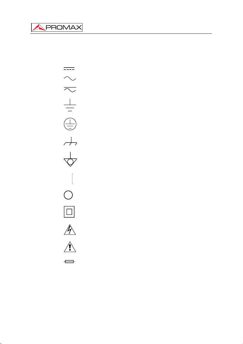
* Symbols related with safety:
DIRECT CURRENT
ALTERNATING CURRENT
DIRECT AND ALTERNATING
(Class II Protection)
(Risk of electric shock)
GROUND TERMINAL
PROTECTIVE CONDUCTOR
FRAME TERMINAL
EQUIPOTENTIALITY
ON (Supply)
OFF (Supply)
DOUBLE INSULATION
CAUTION
CAUTION REFER TO MANUAL
FUSE
Page 12 01/2008
Page 21

USER’S MANUAL. US TV EXPLORER II
2.2 Descriptive Examples of Over-Voltage Categories
Cat I Low voltage installations isolated from the mains.
Cat II Portable domestic installations.
Cat III Fixed domestic installations.
Cat IV Industrial installations.
English
01/2008 Page 13
Page 22

USER’S MANUAL. US TV EXPLORER II
Page 14 01/2008
Page 23
USER’S MANUAL. US TV EXPLORER II
3 INSTALLATION
3.1 Power Supply
The US TV EXPLORER II is a portable instrument powered by one 7.2 V - 11 Ah
Li-Ion battery. There is also an external DC charger provided for mains connection and
battery charging.
3.1.1 Operation using the External DC Charger
Connect the external DC charger to EXT. SUPPLY [32] on the US TV
EXPLORER II
selector [1] for more than two seconds. The level meter is now in operation and the
battery is slowly charged. When the instrument is connected to the mains, the
CHARGER indicator [4] remains lit. This indicator changes of color according to the
battery charge status:
RED
YELLOW
GREEN
3.1.2 Operation using the Battery
the rotary selector [1] for more than two seconds. The fully charged battery can power
the equipment for more than 4.5 hours non-stop.
functioning. In such a situation battery must be recharged immediately.
battery by checking the battery charge level indicator that appears when activating the
side panel. Connect the DC charger to the mains. Then, press the rotary
BATTERY CHARGE STATUS
OFF ON
< 50 % < 90 %
> 50 % > 90 %
100 % 100 %
Table 1.- Indication of the battery charge status (CHARGER).
For the device to operate on the battery, disconnect the power cable and press
If battery is very weak, the battery cut-off circuit will prevent the device from
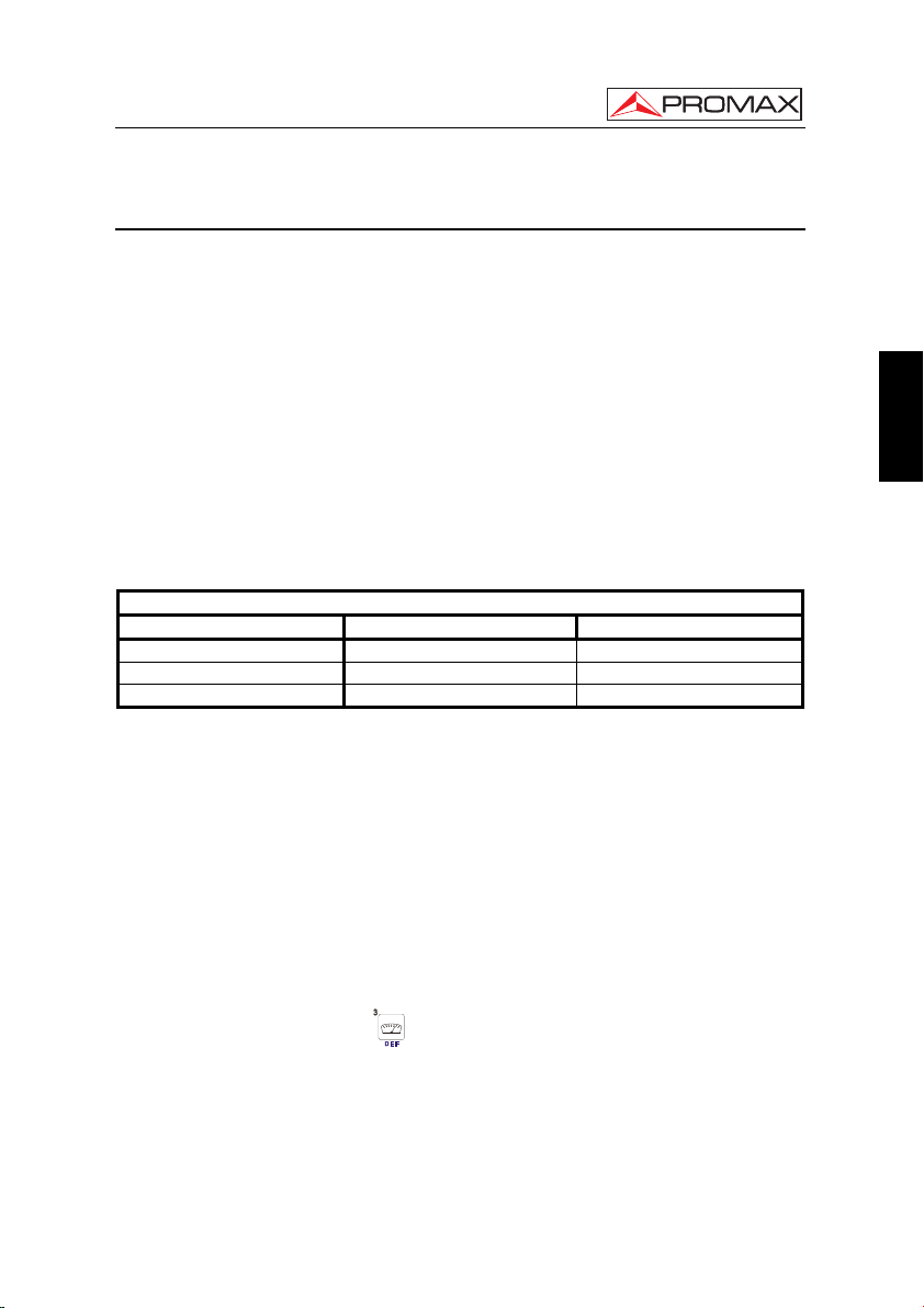
Before taking any measurements, you have to check the charge status of the
English
measurement mode by pressing
01/2008 Page 15
[12] key. These are the indicators on screen:
Page 24
USER’S MANUAL. US TV EXPLORER II
BATTERY CHARGE LEVEL INDICATORS
COLOUR SYMBOL CHARGE LEVEL
GREEN
GREEN
GREEN
3.1.2.1 Battery Charging
Table 2.- Indication of the battery charge level on screen.
75 % ∼ 100 %
30 % ∼ 75 %
10 % ∼ 30 %
Empty battery.
Recharge in progress.
To fully charge the battery, connect the instrument to the external DC charger
without activating the power on process. The length of time it takes to recharge it
depends on the condition of the battery. If they are very low the recharging period is
about 5 hours. The CHARGER [4] indicator should remain lit.
When the battery charging process is completed with the instrument off, the fan
stops.
IMPORTANT
The instrument battery needs to be kept charged between 30% and 50% of its
capacity when not in use. The battery needs to be fully charged for best results. A
fully charged battery undergoes temperature-related discharge. For example, at a
room temperature of 20 °C, it can lose up to 10% of its charge over 12 months.
3.2 Installation and Start-up
The US TV EXPLORER II
therefore does not require installation.
When the rotary selector [1] is pressed for more than two seconds, the instrument
is started up in the automatic power-off mode; that is, the device is automatically
disconnected after the selected minutes if no key has been pressed. When the device is
operating, it is also possible to select the auto power-off mode by means of the
Preferences menu [22] and to select the time out until the automatic power-off.
When the equipment is going to be moved, activate the Transport mode by
means of the Preferences menu [22] to disable the power on process until one specific
key from main keyboard is pressed [8] as is it indicated on screen.
level meter is designed for use as a portable device,
Page 16 01/2008
Page 25
USER’S MANUAL. US TV EXPLORER II
4 QUICK USER GUIDE
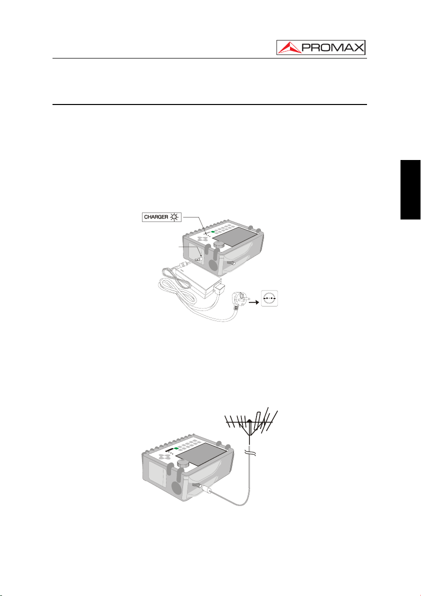
STEP 1.- Battery charging
1. Connect the DC external charger to the equipment through connector [32] located
on the lateral panel.
2. Connect the DC charger to the mains.
3. When the equipment is connected to the mains, the CHARGER led [4] remains
lighted.
DC IN
English
Figure 1.- Battery charging
STEP 2.- Power on and signal connection
1. Hold the rotary selector [1] pressed until the equipment is powered on.
2. Connect the RF signal source in the input connector [30].
Figure 2.- Power on and signal connection.
01/2008 Page 17
Page 26
USER’S MANUAL. US TV EXPLORER II
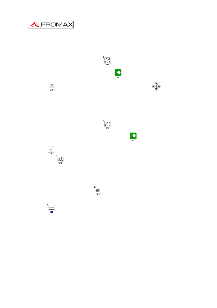
STEP 3.- To carry out a complete channel band exploration
1. Select the frequency band to explore [14] (terrestrial or satellite).
2. Activate the exploration process by holding [25] key pressed.
3. Press [10] key to visualize the channels detected and [6] to change
between channels from detected channels list.
STEP 4.- To carry out the tuned channel identification
1. Select the frequency band to explore [14] (terrestrial or satellite).
2. Activate the identification process pressing once on [25] key.
3. Press [10] key to visualize the signal detected from channel or frequency
identified or
[13] to monitor the corresponding spectrum.
STEP 5.- Making measurements
1. Select the channel or frequency [24] to measure by means of the rotary selector
[1].
2. Press [12] key to select the type of measurement until on screen appears the
corresponding measurement.
Page 18 01/2008
Page 27
USER’S MANUAL. US TV EXPLORER II
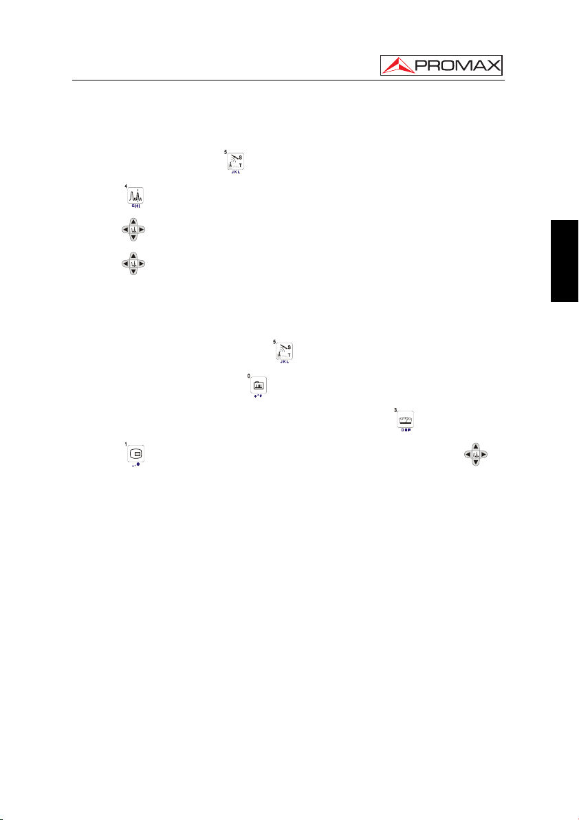
STEP 6.- Frequency spectrum monitoring
1. Select the frequency band to graph [14] (terrestrial or satellite).
2. Press [13] key to activate the signals sweeping.
3. Press [6] to modify the reference level in the vertical axis.
4. Press [6] to modify span in the horizontal axis.
STEP 7.- Video signal monitoring
1. Select the terrestrial frequency band [14].
2. Tune the channel or frequency [24] that is desired to visualize on screen.
3. Verify that the equipment receives an appropriate signal level [12].
4. Press [10] key to visualize the TV image, if the channel is digital press [6]
and place the cursor on the Service Identifier field and press the rotary selector [1]
to obtain the available list of services.
English
01/2008 Page 19
Page 28

USER’S MANUAL. US TV EXPLORER II
Page 20 01/2008
Page 29
USER’S MANUAL. US TV EXPLORER II
5 OPERATING INSTRUCTIONS
WARNING:
The following described functions could be modified based on software updates of
the equipment, carried out after manufacturing and the publication of this manual.
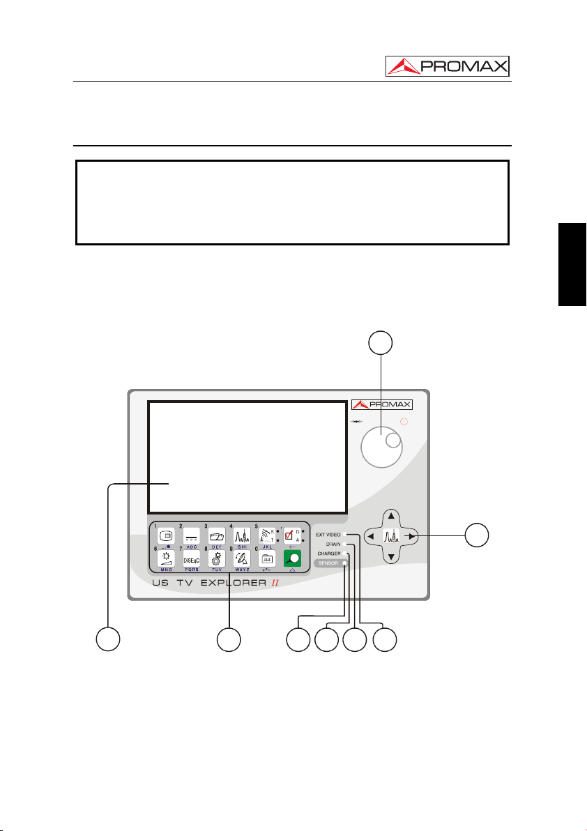
5.1 Description of the Controls and Elements
Front panel
1
English
6
87
Figure 3.- Front panel.
[1] Rotary selector-button. This has many different functions: Equipment power
on/off, tuning control, moving between the various on-screen menus and sub-
menus, and validation of the different options.
01/2008 Page 21
543 2
Page 30

USER’S MANUAL. US TV EXPLORER II
In order to power on the equipment, hold the rotary selector pressed for more
than two seconds until the presentation screen appears.
In order to power off the meter hold the rotary selector pressed.
Tuning purposes: turning it clockwise frequency increases while turning it
anticlockwise frequency decreases.
To move along the on-screen menus: turning it clockwise active option moves
downwards while turning it anticlockwise active option moves upwards.
[2] EXT VIDEO. Video signal presence light indicator
It lights up when video on screen is coming through the RCA connector [35].
[3] DRAIN
External units power supply indicator. Lights up when the US TV EXPLORER II
supplies a current to the external unit.
[4] CHARGER
External DC charger operation indicator. When batteries are installed the battery
charger is automatically activated.
[5] SENSOR
Sensor of environmental luminosity, allows automatic adjusts of the display
contrast and brightness contributing to the battery saving.
[6]
CURSORS
Allow adjust in the Spectrum Analyzer mode of the reference level and the
margin of frequencies to represent (span). As well as the movement through the
different menus and submenus that appear in the monitor.
[7] MONITOR
[8] MAIN KEYBOARD
12 keys to select functions and entering alphanumeric data.
Page 22 01/2008
Page 31

USER’S MANUAL. US TV EXPLORER II
English
Figure 4.- Main keyboard.
[10]
TV KEY
It allows visualizing the image of TV corresponding to the input signal as well as
data relative to the reception of the video signal.
Key number 1 to enter numeric data.
[11]
EXTERNAL UNITS POWER SUPPLY
Enables selecting the power supply to the external units. Available voltages are:
External, 5 V, 13 V, 15 V, 18 V and 24 V for the terrestrial band and External, 5 V,
13 V, 15 V, 18 V, 13 V + 22 kHz and 18 V + 22 kHz for the satellite band.
Key number 2 to enter numeric data.
[12]
MEASUREMENTS
Enables the type of measurement to be selected. The types of measurements
available depend on the band, the standard and the operating mode.
Key number 3 to enter numeric data.
01/2008 Page 23
Page 32

USER’S MANUAL. US TV EXPLORER II
[13]
SPECTRUM/TV
Allows switching between any previous operating mode and the Spectrum
Analyzer mode and vice versa.
Key number 4 to enter numeric data.
[14]
SATELLITE/TERRESTRIAL BAND
Allows switching between the Satellite or Terrestrial TV frequency band.
Key number 5 to enter numeric data.
[15] S
This led remains lighted when the equipment works with the frequencies and the
corresponding channels to the satellite band.
[16] T
This led remains lighted when the equipment works with the frequencies and the
corresponding channels to the terrestrial band.
[17]
MEASUREMENT CONFIGURATION
It allows the commutation between the measurement mode for Digital TV or
Analogue TV.
[18] D
This led remains lighted when the equipment works with digital signals.
[19] A
This led remains lighted when the equipment works with analogue signals.
[20]
IMAGE ADJUST
Activation of VOLUME, CONTRAST, BRIGHT, SATURATION and HUE control
menus.
Key number 6 to enter numeric data.
[21]
DISEqC
(Only in satellite band). It allows adjusting configuration parameters in satellite
band.
Key number 7 to enter numeric data.
Page 24 01/2008
Page 33

USER’S MANUAL. US TV EXPLORER II
[22]
UTILITIES / PREFERENCES
It activates the Utilities menu (short pulsation):
Equipment Info. Displays information on the instrument: (PN) product
number, version of control software, included set-up,
etc.
Constellation Sets the constellation diagram graph for the DVB-S/S2,
ITU-T(QAM-B) and DVB-C (QAM-A) digital signal on
tune.
Attenuation Test (Only terrestrial band).
Selects the function for testing signal distribution
networks in terrestrial band.
Sat IF Test (Only satellite band).
Selects the function for testing signal distribution
networks in satellite band.
Run Datalogger Function to automatically acquire measurements.
View Datalogger Displays the available acquisition list.
Erase Dataloggers Deletes an acquisition previously recorded.
Delete Channel Set Delete the channel plan selected.
Delete Channels Delete a channel from the active channel plan.
Insert Channels Add a channel to the current channel plan from another
standard list of channels.
Save as: Saves with a file name the capture screen in order to be
later processed.
Recall Constell
8
Recall a constellation diagram stored in memory.
Recall Spectrum Recall a signal spectrum previously stored.
Delete Capture Allows to delete a screen capture file.
Exit Exit from Utilities.
English
8
Only DVB-S/S2, QAM-A and ITU-T J.83/B.
01/2008 Page 25
Page 34

USER’S MANUAL. US TV EXPLORER II
It activates the Preferences menu (long pulsation):
Language Selects the language between DEUTSCH, ENGLISH,
ESPAÑOL, FRANÇAIS, ITALIANO, CATALÀ,
РУССКИЙ and PORTUGUÊS.
Beep Activates (ON) / deactivates (OFF) the beeper.
Skin Sets the display skin. It is possible to add new types
through the USB port.
Light Sensor It activates a light sensor to automatically adjust the
display contrast and brightness. Options are: High
contrast (with low luminosity), Low contrast (with high
luminosity) and AUTO.
Min. Ter. Power Sets the minimum power for a terrestrial digital signal to
be identified.
Min. Ter. Level Sets the minimum level for a terrestrial analogue signal
to be identified.
Identification DVB-S2 It allows to identify the DVB-S2 satellite digital signals.
Min. Sat. Power Sets the minimum power for a satellite digital signal to
be identified.
C/N Defines the C/N measuring method between Auto or
Reference Noise (Manual), used to determine the
frequency where noise level will be measured in the
spectrum analyzer mode.
Identify Timeout Sets the maximum time that the equipment will carry
out the identification of a channel unknown before going
to the next one.
Sat Band (Only satellite band).
Selects the C-band or Ku-band for tuning satellite
signals.
Auto Power Off Activates the automatic power off mode.
Time Power Off Select the power off timeout between 1 and 120
minutes.
Terrestrial Units Select the measurements units for terrestrial and cable:
dBµV, dBmV or dBm.
Page 26 01/2008
Page 35

USER’S MANUAL. US TV EXPLORER II
Satellite Units Select the measurements units for satellite: dBµV,
dBmV or dBm.
Rotary Selector Select the movement sense: CW (clockwise) or CCW
(counterclockwise).
PRN-23 BER Turns ON or OFF the PRN-23 BER option.
Ref. level It selects the most suitable range when accessing to the
spectrum analyzer mode: MANUAL (defined by the
user) or AUTO (calculated by the instrument).
Transport Mode It activates or it deactivates the automatic power off
function for transportation. So, it allows to prevent an
accidental start-up of the equipment.
Exit Exit from preferences menu
Key number 8 to enter numeric data.
English
[23]
Key number 9 to enter numeric data.
[24]
Key number 0 to enter numeric data.
[25]
01/2008 Page 27
ANTENNA ALIGNMENT
Tool for faster sweep antenna alignment at terrestrial and satellite bands.
Displays the measurements by means of a graph level bar.
TUNING BY CHANNEL OR FREQUENCY
Switches tuning mode between channel and frequency. (quick pulsation).
In channel mode the tuning frequency is defined by the active channels table
(FCC, ...).
It visualizes the listing of channel plans available (slow pulsation).
AUTO ID/ EXPLORER
Activates the automatic identification function (short pulsation):
The instrument will try to identify the signal under test.
First it recognizes whether the signal is an analogue channel or a digital one.
If the channel is analogue, it determines the television standard of the signal
detected.
Page 36

USER’S MANUAL. US TV EXPLORER II
When the signal is digital, it analyses the modulation type: QAM Annex-B /
QAM Annex-A / QPSK / 8PSK / 8-VSB and all the associated parameters
such as the symbol rate, the code rate, etc.,. and it tries to lock to the signal.
In the spectrum analyzer mode it appears on screen the name of the network
and the orbital position (only in satellite band).
Activates the band exploration function (long pulsation):
The meter explores the entire frequency band to identify the analogue and
digital channels present.
Figure 5.- Top panel view.
30
[30] RF RF signal input
Maximum level 70 dBmV. Universal connector for F/F or F/BNC adapter, with
input impedance of 75 Ω.
ATTENTION
Use the 10 dB attenuator (AT-010) to protect the RF [30] input
whenever the input signal level is greater than 70 dBmV (3.16 V) or when
suspecting of intermodulation problems.
This accessory allows DC voltages to pass when powering external units as
LNB and amplifiers.
Page 28 01/2008
Page 37

USER’S MANUAL. US TV EXPLORER II
10 dB ATT
Figure 6.- Connecting external attenuator on RF input [30].
ATTENTION
Note the importance to protect the RF [30] input signal with an
accessory to block the AC voltages used in CATV cables (necessary to feed
amplifiers) and operate in remote mode.
English
34 35 33323136
Figure 7.- Lateral panel elements.
[31] RESET button
Allows to restart the instrument if occurs any abnormality while operating.
[32] External 12 V power supply input
01/2008 Page 29
Page 38

USER’S MANUAL. US TV EXPLORER II
[33] Loudspeaker
[34] Fan
[35] RCA adapter
[36] Transport belt hook
Figure 8.- Rear panel view.
37
[37] USB Connector
It enables the communication with a PC, and to download dataloggers and
channel plans.
5.2 Adjustment of Volume and Monitor Parameters
Repeatedly pressing the
CONTRAST, BRIGHTNESS, SATURATION and HUE control menus. On activation of
a menu for a specific parameter the screen displays a horizontal bar whose length is
proportional to the parameter level, to modify this value simply turn the rotary selector
[1]. To exit the menu and validate the new value press the rotary selector [1].
Page 30 01/2008
[3] key sequentially activates the VOLUME,
Page 39

USER’S MANUAL. US TV EXPLORER II
5.3 Selecting the Operation Mode: TV / Spectrum Analyzer /
Measurements
The US TV EXPLORER II has three basic operation modes: TV, Spectrum
Analyzer and Measurements. To switch from TV operation mode to the Spectrum
Analyzer press
In TV operation mode the demodulated television signal is shown on-screen; this
is the default operation mode, various functions can be selected, as shown in the
following paragraphs.
In Spectrum Analyzer operation mode the screen displays the spectrum of the
active band (terrestrial or satellite). The span and the reference level.
In Measurement mode the screen shows the available measurements according
to the type of signal selected.
[13] key. To switch to the Measurements mode press [12] key.
5.4 Channel Tuning / Frequency Tuning
Pressing
channel tuning and back again.
In channel tuning mode turning the rotary selector [1] sequentially tunes the
channels defined in the active channels table. When turning it clockwise frequency
increases while turning it anticlockwise frequency decreases.
In frequency tuning mode there are two ways of tuning:
1. Turning the rotary selector [1].
Turning the rotary selector [1] selects the desired frequency (tuning is
continuous from 5 to 1000 MHz and from 950 to 2150 MHz). When turning it
clockwise frequency increases while turning it anticlockwise frequency
decreases.
2. Using the keyboard.
Press the rotary selector [1] (the frequency listing will disappear and will
appear on the upper left corner of screen the keyboard symbol of manual data
[24] key the US TV EXPLORER II switches from frequency tuning to
English
entry
keyboard. The US TV EXPLORER II will calculate the tuneable frequency
closest to the entered value and then display it on-screen.
01/2008 Page 31
), next enter the frequency value in MHz using the numeric
Page 40

USER’S MANUAL. US TV EXPLORER II
5.5 Automatic Transmission Search
Holding pressed the
When tuning a channel the instrument tries to identify it and save it with the
configuration. If the identification is not possible the channel is removed from list. As a
result obtains a new channel plan that only contains the channels that have been
identified.
[25] key search starts over the active channel plan.
5.6 Selecting the measurement configuration: Analogue/ Digital signal
Measuring the characteristics of a channel depends, in the first place, on the type
of modulation: analogue or digital.
Use key
[20] key to show the measurements CONFIGURATION menu and select the
Signal option by turning and pressing the rotary selector [1]. The Signal option allows
setting the type of signal to measure. When switching to a new type, the US TV
EXPLORER II activates the last measurement configuration used for that type of signal.
[20] to switch between analogue and digital channels. Press the
5.7 External Units Power Supply
The US TV EXPLORER II can supply the voltage needed to power the external
units (antenna preamplifiers, in the case of terrestrial TV, LNB in the case of satellite
TV, or IF simulators).
In order to select the supply voltage of the external units, press
the screen will display a functions menu labeled EXT. SUPPLY listing the choice of
voltages (which will depend on the band being used). Turn the rotary selector [1] to the
desired voltage and press to activate it. The following table shows the choice of supply
voltages:
Band Powering voltages
SATELLITE
External
5 V
13 V
15 V
18 V
24 V
13 V + 22 kHz
18 V + 22 kHz
[11] key, and
Page 32 01/2008
Page 41

USER’S MANUAL. US TV EXPLORER II
Band Powering voltages
TERRESTRIAL
MATV
Table 3.- External units powering voltages.
External
5 V
13 V
15 V
18 V
24 V
In the External power supply mode is the unit powering the amplifiers before the
antenna (terrestrial television) or the satellite TV receiver (house-hold or community)
also powers the external units.
The DRAIN [3] indicator lights when current is flowing to the external unit. If any
kind of problem occurs (e.g., a short circuit), an error message appears on the monitor
('SUPPLY SHORT'), the acoustic indicator will be heard and the instrument will cease
to supply power. The US TV EXPLORER II
does not return to its normal operating state
until the problem has been solved, during this time it verifies every three seconds the
persistence of the problem warning with an acoustic signal.
5.8 Automatic signal identification function (AUTO ID)
The US TV EXPLORER II allows automatically identifying TV signals, according
to the established configuration, which are presents in the channel or tuned frequency.
English
In order to activate this function must once press
combine this process with the spectrum monitoring
[25] key. Specially useful, is to
[13], so that after locating the
marker on the levels susceptible to contain a transmission, and activating later the
process of automatic identification in order to identify the present signal.
FREQ:
CHANNEL:
TESTING FOR ANALOG
NOT ENOUGH LEVEL 46.2 < 50.0 dBµV
TESTING 8-VSB
POWER OK 51.6 >= 32.0 dBµV
TRYING CURRENT 8-VSB CONFIG.
DIGITAL: 8-VSB
SEARCHING NETWORK NAME
CANCEL
Figure 9.- Signal automatic identification screen. AUTO ID.
01/2008 Page 33
753.25 MHz61DL: 753.25 MHz
Page 42
USER’S MANUAL. US TV EXPLORER II
First it recognizes whether the signal is an analogue channel or a digital one. If
the channel is analogue, it determines the television standard of the signal. When the
signal is digital (ATSC, ITU-T J.83/B, DVB-C, DVB-S and DSS), it analyses for each
modulation type QAM Annex-A / QAM Annex-B / QPSK / 8QPSK / 8-VSB all the
associated parameters such as the modulation system: carriers, symbol rate, code
rate, etc.,. and determines the value of the signals under test.
If the AUTO ID function is launched in the spectrum analyzer mode, the name of
the network will appear temporarily on screen (it also appears in the measurement
display). In case of working in the satellite band the orbital position appears as well.
Whenever the process detects new parameters for a channel or frequency will
create a new channel plan containing the detected information.
NOTE: The icon in the upper corner of a digital measurement screen states
that the signal level is higher than the minimum threshold (see the
PREFERENCES menu) but demodulator cannot lock it maybe due to
some wrong configuration parameter.
In such case, the user must press AUTO ID [25 ] key.
NOTE: In order to identify DVB-S2 signals will be necessary to activate previously
the DVB-S2 option for digital satellite signals in the [22]
PREFERENCES menu.
5.9 Channel plans
The signal automatic identification process as much as the exploration of the
frequency spectrum could yield the generation of new customized channel plans
relative to the usual work locations of the meter equipment.
In this way the characterization of the band will be faster and easier when causing
that the equipment only analyses a shorter set of channels.
Page 34 01/2008
Page 43

USER’S MANUAL. US TV EXPLORER II
Whenever a new process of exploration is activated, the US TV EXPLORER II
analyses all the present channels in the active channel plan, which acts as pattern
channel plan specified by means of the option CHANNEL SET from configuration
measurement menu: CONFIGURATION
[17].
If during exploration or automatic identification process the
EXPLORER detects
new parameters for some channel or frequency a new list will be generated with the
information updated and will be saved with the name of the original channel plan
followed by the extension: _0x. (See the following Figure).
STD CHANNEL PLAN
+ PARAMS. NEW CHANNEL PLAN
EXPLORER
FCC:
FCC_01:
A02 A03 A04 A05 A06 A07 67 68 69
A02 A04 A07 15 65 68
AUTO ID
FCC:
FCC_01:
A02 A03 A04 A05 A06 A07 67 68 69
A02 A03 A04 A05 68 69
Figure 10.- New channel plan generation process.
STD CHANNEL PLAN
+ PARAMS. A04
Those channels that have not been identified during the exploration process are
removed from the new generated channel plan. The user can save this table in the
memory, modify its name and later use it by means of the CONFIGURATION
[17]
menu.
Also can delete any channel list, or remove and add channels from another
English
standard list by means of the editing options offered by the
UTILITIES [22] menu.
01/2008 Page 35
Page 44

USER’S MANUAL. US TV EXPLORER II
CHANNEL SET
FCC
EIA
10 30 50 70 90 110 130
FREQ:
CH:
MPEG-2
HRC
IRC
57.00
EXIT
-3
A02
Figure 11.- Channel plans listing.
MHz
kHz
C/N:
POWER:
»
MER:
SER:
VBER:
>21.3
55.8
19.5
1.0E-5
1.0E-8
dB
dBµV
dB
Keep the
[24] key pressed in order to accede to the listing of channel plans
available in the instrument and later select the current channel plan by means of the
rotary selector [1].
The
EXPLORER allows directly changing the tuned channel pertaining to the active
channel plan by means of the horizontal
the channel-tuning field
[24] and in the TV [10] and MEASUREMENTS
cursors [6]. From this way, once selected
[12] operation modes is possible to check cyclically the entire active channel list.
NOTE: The icon in the upper corner of the screen indicates that the
equipment is carrying out an internal operation and user must wait to
complete it.
5.10 Acquisition function (DATALOGGER)
The Datalogger function allows the user to carry out and store measurements in
a fully automatic way. It can store for each acquisition the measurements made in
different points of the installation. The measurements made are relevant to the current
analogue or digital channel, in the active channel plan.
To select the Datalogger function, activate the UTILITIES
select the RUN DATALOGGER option. Later, by turning the rotary selector [1] select a
previously stored acquisition or a NEW DATALOGGER.
[22] menu and
Page 36 01/2008
Page 45
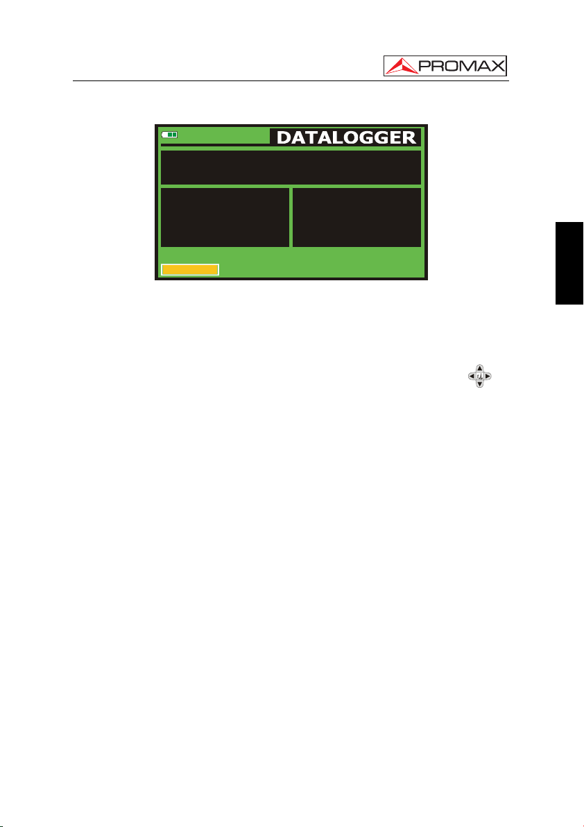
USER’S MANUAL. US TV EXPLORER II
14/41
TEST POINT:
CHANNEL SET:
FREQ:
CH:
8-VSB. MEASURING... 16 Sec.
CANCEL
63.00
-1
A03
Figure 12.- DATALOGGER screen.
DATALOGGER_00
POINT_01
LEMSFORD
MHz
C/N:
kHz
POWER:
MER:
SER:
VBER:
7.5
dB
52.1
dBµV
<13
dB
>7.7E-2
1.0E-1
In the case of digital channels, which require a greater calculation process, a
timer counter will appear in the lower part of the screen. In the upper corner the channel
number being measured will appear, followed by the total number of channels in the
current channel plan.
In order to select the different fields on the screen, press the cursor keys [6]
and then edit by pressing the rotary selector [1].
After selecting the START field the instrument begins to carry out the available
measurements automatically. Once completed, the process will be ready to repeat
again (for example, for a new test point), or view measured data by turning the rotary
selector [1], or store the information in memory (SAVE) or exit from this acquisition
(EXIT).
5.10.1 DATALOGGER for Attenuation and IF SAT tests
The US TV EXPLORER II allows to make measurement acquisitions while
executing an Attenuation test at terrestrial band or an IF SAT test at satellite band
(see section “5.11 Verification of distribution networks”).
For it, one of these tests should be activated previously as the following figure
shows.
English
01/2008 Page 37
Page 46

USER’S MANUAL. US TV EXPLORER II
10
0
-10
-20
FREQ:
REF:
TEST:
ATT:
229.70
90.6
86.3
Figure 13.- Attenuation Test. Terrestrial band.
4.3
519.25
83.7
73.1
10.6
631.25
83.6
70.2
13.4
EXITCALIBRATE
MHz
dBmV
dBmV
dB
In order to make the automatic acquisition of these measurements, select it from
UTILITIES menu by pressing the [22] key, and activating the RUN DATALOGGER
option, and later the NEW DATALOGGER option. In the CHANNEL SET field will
appear the type of test that the instrument is going to store automatically.
TEST POINT:
CHANNEL SET:
FREQ:
CH:
READY TO START
START SAVE EXIT
229.70
- - -
Figure 14.- Datalogger screen for Attenuation test frequencies.
PINEMALLCTR
PREMISE1
ATTENUATION TEST
REF:
MHz
LEVEL:
kHz
- - -
- - -
dBmV
dBmV
Once the START option is selected the instrument will capture all test values
corresponding to the three pilot frequencies in the active band. When measuring is
completed, it will offer the options to store data or to start a new acquisition.
Page 38 01/2008
Page 47

USER’S MANUAL. US TV EXPLORER II
FINISHED
TEST POINT:
CHANNEL SET:
FREQ:
CH:
START SAVE EXIT
229.70
- - -
PILOT_01
Figure 15.- End of data acquisition.
PINEMALLCTR
PREMISE1
ATTENUATION TEST
REF:
MHz
LEVEL:
kHz
90.6
80.3
dBmV
dBmV
NOTE: In order to select the function (Attenuation test or IF SAT test) might be
necessary to switch the frequency band between Terrestrial or Satellite by
means of the front panel
key [10].
5.11 Verification of distribution networks
(SAT IF Test / Attenuation Test)
This application allows to verify easily the TCI features (Telecommunications
Common Infrastructures) before the antennas and head-end devices are operative. The
procedure allows to evaluate the frequency response of a whole TV signals distribution
network by means of two steps:
NOTE: For this application the use of PROMAX’s RP-050 and RP-080 or RP-250
signal generators are required, for which they have been specially
designed.
1.- CALIBRATION
Connect the signal generator directly to the US TV EXPLORER II using the
BNC-F adapter.
Power on the RP-050/RP-080 through the EXPLORER, for it is necessary to set
the External supply function (see section '5.7 External Units Power Supply') pressing
English
[11], and the rotary selector [1] for setting a voltage of 13 V.
key
Finally, select the SAT IF TEST application on UTILITIES [22] menu for SAT
band, or the ATTENUATION TEST for terrestrial band, connect the signal generator to
the point where antenna will be connected (signal source).
01/2008 Page 39
Page 48

USER’S MANUAL. US TV EXPLORER II
Press the
[17] key to see on screen the measurement CONFIGURATION.
By means of the Threshold Attenuation option is possible to adjust the maximum
difference between the pilots reference level from -55 to 10 dBmV.
Later, by means of the horizontal cursors
[6] key, select the Calibrate
function (see the following figure). Wait for some seconds until the calibration process
for three pilots is completed:
MEASURING REF. is indicated on screen while this process
is in progress.
10
0
-10
-20
FREC:
REF:
TEST:
ATT:
1294.89
Figure 16.- SAT IF Test. Satellite band.
84.7
84.5
0.2
1403.94
90.2
90.2
0.0
2130.99
100.3
99.1
1.2
MHz
dBµV
dBµV
dB
EXITCALIBRATE
The calibration process must be carried out over the point of the installation which
is taken as reference, i.e. usually the headend. During this process is determined the
number of pilot frequencies to check, from one to three, in addition to the reference level
for pilots. In order to determine the number of pilots, the equipment takes the higher
found level and verifies that the other pilots have a non lower level to the reference one
plus the defined threshold level. If the pilot agrees this condition it will show on screen.
2.- MEASUREMENT OF THREE PILOTS THROUGHOUT THE NETWORK
Once US TV EXPLORER II has been calibrated, start to make level
measurements in the different distribution outlets using the
EXPLORER. On the
screen will appear the attenuation values for the three pilot frequencies measured in the
outlet plate (see the following figure).
Page 40 01/2008
Page 49

USER’S MANUAL. US TV EXPLORER II
10
0
-10
-20
FREC:
REF:
TEST:
ATT:
1294.89
Figure 17.- Attenuation measurements in an outlet plate.
84.7
80.7
4.0
1403.94
90.2
84.2
6.0
2130.99
100.3
77.6
22.7
MHz
dBµV
dBµV
dB
EXITCALIBRATE
In order to finish measuring, press the rotary selector [1] and select the (EXIT)
option.
5.12 Spectrum exploration function (EXPLORER)
The Exploration function allows exploring the full frequency band in order to
identify the analogue channels and digital presents, in agreement with the configuration
English
set, over the active channel plan. In order to activate this function the
[25] key must
be pressed until the EXPLORER screen appears.
TESTING CHANNEL SET:
0 25 50 75 100%
66
67
68
69
FOUND: 12 / 101
PROCESS SUCCESSFUL
EXIT
Figure 18.- Spectrum exploration screen. EXPLORER.
8-VSB OK
UNIDENTIFIED
ANALOG: NTSC-M
NO SIGNAL
SAVE AS: STATION1
PROMAX
When the instrument completes the exploration, a new channel plan is generated
based on the active channel plan. This new channel plan contains only the channels
that have been identified and the rest are removed. The equipment offers the possibility
of saving in memory the channel plan generated to use later. If the new channel plan is
not saved it will remain active until the instrument is powered off or some other plan is
loaded.
01/2008 Page 41
Page 50

USER’S MANUAL. US TV EXPLORER II
5.13 Measurements configuration
With the aim of taking the measurements of all types of signals some times could
be necessary that user enters parameters relative to particular characteristics of these
signals, whether an automatic detection has not been possible, or these parameters
differ from the standard corresponding ones.
Press the Measurements Configuration
[17] key to access to the
CONFIGURATION menu and turn the rotary selector [1] to access to parameters, which
are modifiable by the user.
5.13.1 ITU-T J.83/B (QAM Annex-B) Digital Channel Configuration
Press the Measurements Configuration
CONFIGURATION menu and turn the rotary selector [1] to access the QAM Annex-B
signals parameters, which can be defined by user and are described below:
1) Spectral inversion
If necessary, activate the Spectral inversion (On). If the spectral inversion is not
correctly selected, reception will not be correct.
2) Modulations
It defines the modulation type. When selecting this function and pressing the
rotary selector [1] a multiple-choice menu will appear on the screen, this menu
permits to choose one of the following modulations: 64 or 256.
CONFIGURATION
» CHANNEL SET:
» SIGNAL:
10 30 50 70 90 110 130
FREQ:
CH:
SYSTEM:
FRAME RATE:
213.00
CHANNEL BW:
» SPECTRAL INV:
SYMBOL RATE:
» MODULATION:
EXIT
A13
MHz
kHz
-3
C/N:
POWER:
»
MER:
BER:
[17] key to access to the
ITU-T J.83/B
5361kSymb
FCC
NTSC
60Hz
16.5
6.00MHz
66.2
OFF
24.7
5.6E-7
256QAM
dB
dBµV
dB
Figure 19.- Screen of measurement configuration (QAM Annex-B signals).
Page 42 01/2008
Page 51

USER’S MANUAL. US TV EXPLORER II
5.13.2 DVB-C (QAM) Digital Channel Configuration
Press the Measurements Configuration
[17] key to access to the
CONFIGURATION menu and turn the rotary selector [1] to access the QAM signals
parameters, which can be defined by user and are described below:
1) Spectral inversion
If necessary, activate the Spectral inversion (On). If the spectral inversion is not
correctly selected, reception will not be correct.
2) Symbol Rate
When selecting this function and pressing the rotary selector [1] is possible to
choose the symbol rate.
3) Modulation
It defines the modulation type. When selecting this function and turn the rotary
selector [1] to choose one of the following modulations: 16, 32, 64, 128 and 256.
CONFIGURATION
» CHANNEL SET:
» SIGNAL:
10 30 50 70 90 110 130
FREQ:
CH:
MPEG-2 TS
Figure 20.- Screen of measurement configuration (QAM signals).
» SYSTEM:
» FRAME RATE:
650.00
» CHANNEL BW:
-3
» SPECTRAL INV:
43
» SYMBOL RATE:
» MODULATIONS:
EXIT
MHz
kHz
C/N:
» POWER:
MER:
BER:
CCIR
DVB-C
PAL
50Hz
16.5
8.00MHz
66.2
OFF
24.7
6875kSymb
3.4 E-4
64QAM
dB
dBµV
dB
5.13.3 ATSC (8-VSB) Digital Channel Configuration
English
Press the Measurements Configuration
[17] key to access to the
CONFIGURATION menu and turn the rotary selector [1] to access the 8-VSB signals
parameters, which can be defined by user and are described below:
1) Spectral Inv. (spectral inversion)
This option enables spectral inversion to be applied to the input signal, though in
the majority of cases it should be in the OFF position (not inversion).
01/2008 Page 43
Page 52

USER’S MANUAL. US TV EXPLORER II
CONFIGURATION
» CHANNEL SET:
» SIGNALL:
YSTEM
10 30 50 70 90 110 130
FREQ:
CH:
MPEG-2
Figure 21.- Screen of measurements configuration (8-VSB signals).
S:
FRAME RATE
57.00
CHANNEL BW
» SPECTRAL INV:
A02
EXIT
:
MHz
:
kHz
-3
C/N:
»
POWER:
MER:
SER:
VBER:
FCC
8-VSB
NTSC
60Hz
>21.3
6.00MHz
55.8
OFF
19.5
1.0E-5
1.0E-8
dB
dBµV
dB
5.13.4 DVB-S/S2 (QPSK/8PSK) Digital Channel Configuration
Press the Measurements Configuration
[17] key to access to the
CONFIGURATION menu and turn the rotary selector [1] to access the QPSK/8PSK
signals parameters which can be defined by user and are described below:
1) Channel BW (channel bandwidth)
Enables the channel bandwidth to be selected over a range from 1.3 MHz to
60.75 MHz. The selection of this parameter is essential for the correct operation
of the tuner, as it affects the frequency separation of the carriers.
2) Spectral Inv
If necessary, activate the Spectral inversion (On). Reception will be bad if
spectral inversion has been incorrectly selected.
3) Code Rate
Also known as Viterbi ratio. It defines the ratio between the number of data bits
and actual transmission bits (the difference corresponds to the control bits for
error detection and correction).
In DVB-S it permits to choose between 1/2, 2/3, 3/4, 5/6 and 7/8. In DVB-S2 it
permits to choose one of the following values: 1/4, 1/3, 2/5, 1/2, 3/5, 2/3, 3/4, 4/5,
5/6, 8/9 y 9/10.
4) Symbol Rate
It is possible to choose over the following values: from 1000 to 45000 kbauds.
When selecting the option appears the current value, in order to modify it enter a
new value through keyboard when appears the data enter symbol appears on the
upper left corner screen.
Page 44 01/2008
Page 53

USER’S MANUAL. US TV EXPLORER II
When altering this parameter modifies automatically the value of the Channel
Bandwidth and vice versa, due to the relation that exists between these two
parameters.
CONFIGURATION
» CHANNEL SET:
» SIGNAL:
10 30 50 70 90 110 130
FREQ:
DL-Ku:
CH:
MPEG-2
Figure 22.- Screen of measurement configuration (QPSK signals).
» SYSTEM:
» FRAME RATE:
1781.94
» CHANNEL BW:
» SPECTRAL INV:
12382.0
» CODE RATE:
» SYMBOL RATE:
» POLARIZATION:
5037
99
MHz
kHz
MHz
C/N:
» POWER:
MER:
CBER:
VBER:
ASTRA-VL
DVB-S
PAL
50Hz
0.2
29.70 MHz
51.5
OFF
10.9
5/6
22000kSymb
VERT/RIGHT
9.7E-4
5.2E-8
dB
dBµV
dB
5) Modulations (Only in DVB-S2)
Modulation used by carriers. It defines also the system noise immunity (QPSK
and 8PSK).
6) Polarization
It affects to the signal reception in the SAT band (satellite). It allows to select the
signal polarization among Vertical/Right (vertical and circular clockwise) and
Horizontal/ Left (horizontal and circular counterclockwise) or, to deactivate the
polarization (
OFF).
7) Sat Band
Selects the High or Low frequency band for satellite channel tuning.
8) LNB Low Osc.
Sets the LNB low band local oscillator.
9) LNB High Osc.
Sets the LNB high band local oscillator.
NOTE: In the channel tuning mode the Polarization and Sat Band options cannot
be modified.
English
01/2008 Page 45
Page 54

USER’S MANUAL. US TV EXPLORER II
This configuration menu shows, besides the QPSK/8PSK signal parameters
selected by user, all the values automatically detected:
Roll Off Nyquist filter roll-off factor.
Pilots (Only in DVB-S2) Pilots detection in transmission.
IMPORTANT REMARK
DVB channels tuning may require an adjusting process. It is recommended to follow
next procedure:
1. From the spectrum analyzer mode [13], tune the channel at its central
frequency.
2. Switch to Measurements mode
[12], measurement selection.
3. If in the lower line of the screen does not appear MPEG-2 message (and
consequently BER is unacceptable), by turning the rotary selector deviate the tuning
frequency until MPEG-2 message appears. Finally tune channel again to minimize
the frequency deviation which optimizes the BER and therefore minimize the
BER.
If it is not possible to detect any MPEG-2 channel, make sure that digital signal
parameters are correctly defined.
5.13.5 DSS (QPSK) Digital Channel Configuration
Press the Measurements Configuration
CONFIGURATION menu and turn the rotary selector [1] to access the QPSK signals
parameters which can be defined by user and are described below:
1) Channel BW (channel bandwidth)
Enables the channel bandwidth to be selected. The selection of this parameter is
essential for the correct operation of the tuner, as it affects the frequency
separation of the carriers.
2) Spectral Inv
If necessary, activate the Spectral inversion (On). Reception will be bad if
spectral inversion has been incorrectly selected.
[17] key to access to the
Page 46 01/2008
Page 55

USER’S MANUAL. US TV EXPLORER II
3) Code Rate
Also known as Viterbi ratio. It defines the ratio between the number of data bits
and actual transmission bits (the difference corresponds to the control bits for
error detection and correction).
It permits to choose between 1/2, 2/3 and 6/7.
CONFIGURATION
» SIGNAL:
» SYSTEM:
10 30 50 70 90 110 130
FREQ:
CH:
MPEG-2
Figure 23.- Screen of measurement configuration (DSS signals).
FRAME RATE:
CHANNEL BW:
1936.01
» SPECTRAL INV:
» CODE RATE:
11686.0
SYMBOL RATE
ROLL OFF
» POLATIZATION
---
32
MHz
kHz
MHz
C/N:
» POWER:
MER:
20000kSymb
CBER:
VBER:
HORIZ/IZQ.
DSS
NTSC
60Hz
37.12MHz
0.2
OFF
51.5
6/7
10.9
9.7E-4
0.20
5.2E-8
dB
dBµV
dB
4) Polarization
It affects to the signal reception in the SAT band (satellite). It allows to select the
signal polarization among Vertical/Right (vertical and circular clockwise) and
Horizontal/ Left (horizontal and circular counterclockwise) or, to deactivate the
polarization (
OFF).
5) Sat Band
Selects the High or Low frequency band for satellite channel tuning.
6) LNB Low Osc.
Sets the LNB low band local oscillator.
7) LNB High Osc.
Sets the LNB high band local oscillator.
5.14 Selecting the Measurements
The types of measurements available depend on the operating band (terrestrial or
satellite) and the type of signals (analogue or digital).
Terrestrial band - Analogue channels:
Level Level measurement of the currently tuned carrier.
Video / Audio Video carrier to audio carrier ratio.
English
01/2008 Page 47
Page 56

USER’S MANUAL. US TV EXPLORER II
C/N Ratio between the modulated signal power and the equivalent
noise power for a same bandwidth. (according to TV standard)
FM Deviation Measure the frequency peak deviation for any modulated
analogue carrier in FM.
Terrestrial band - Digital channels (ITU-T J.83/B (QAM Annex-B) and ATSC (8-VSB)):
Channel power Channel power is measured assuming that power spectral
density is uniform throughout channel bandwidth.
MER Modulation error ratio measurement.
SER (only for ATSC) MPEG wrong packets measurement, which
have not been corrected by means of the FEC.
VBER (only for ATSC) BER (Bit error rate) measurement for the digital
signal after the error correction (BER after Viterbi).
BER (only for ITU-T J.83/B and DVB-C) BER (Bit error rate)
measurement for the digital signal after the error correction
(BER after Viterbi).
C/N Out-channel measurement. Noise level is measured at f
f
± ½*Channel BW. To measure it correctly digital
tuning
noise
channel must be tuned at its central frequency.
NOTE: The VBER measurement shown by default (when PRN-23 BER option from
Preferences menu is set to OFF) yields an estimated value calculated using
the MER measurement. In order to obtain a more accurate BER
measurement value, the PRN-23 BER option from Preferences menu must be
set to ON and a PRN-23 signal pattern must be used through the RF signal
input [30].
If the input signal is like PRN-23 or a video signal, the BER and VBER
measurement are considered as acceptable when BER/VBER ≤ 3*10E-6 and
SER-ERR/s ≤ 2 being SER value the number of wrong packets taken as
reference measurement.
Satellite band - Analogue channels
Level Level measurement of the currently tuned carrier.
C/N Ratio between the modulated signal power and the equivalent
noise power for a same bandwidth.
=
Page 48 01/2008
Page 57

USER’S MANUAL. US TV EXPLORER II
Satellite band - Digital channels (DVB-S/S2 and DSS):
Channel Power Automatic method.
C/N Ratio between the modulated signal power and the equivalent
noise power for a same bandwidth.
MER Modulation error ratio with noise margin indication (only for
DVB-S and DSS).
CBER The BER measurement (Bit error rate) for the digital signal
before error correction (BER before FEC).
VBER (Only for DVB-S and DSS) The BER measurement (Bit error
rate) for the digital signal after error correction (BER after
Viterbi).
LBER (Only for DVB-S2) The BER measurement (Bit error rate) for
the digital signal after error correction (BER after LDPC).
English
In order to change the measurement mode press
[12] key. On the monitor will
appear cyclically all the measures available for the tuned signal.
5.14.1 Analogue TV: Measuring the Video Carrier Level
In the measurement mode of analogue signals, the US TV EXPLORER II, monitor
can work as an analogue indicator of level representing the signal present in the input.
In order to change the measurement mode press
screen like the following one:
10 30 50 70 90 110 130
FREQ:
CH:
Figure 24.- Analogue signal level measurement in terrestrial band.
01/2008 Page 49
S10
MHz168.25
» LEVEL:
C/N
V/A:
FM DEV:
[12] key, it will appear a
dBµV
78.2
dB
40.1
dB
16.2
kHz
- - -
Page 58

USER’S MANUAL. US TV EXPLORER II
Turn the rotary selector [1] to change the tuning channel/frequency. Press the
[12] key to select the type of measurement to visualize on the monitor.
The available types of measurements are:
LEVEL: Level indication on the upper part of the screen (analogue
C/N: Carrier / Noise ratio measurement.
V/A: Video / Audio ratio measurement.
FM Deviation: Measure the frequency peak deviation for any modulated
bar).
analogue carrier in FM.
WARNING
When at the RF input appear an important number of carriers with a high level the
tuning circuit may become out of control, giving as a result wrong level measurements.
To be able to determinate the equivalent level of a carrier group (with similar levels) at
the RF input, it is possible to use the expression:
Lt=L + 10 log N
So, if there are ten carriers with a level around 90 dBµV, their equivalent level will be:
Observe that in this case, loss of tuning by overload of the RF input may occur besides
other effects such as tuner saturation and generation of intermodulation products that
may mask the spectrum visualization.
Lt: equivalent total level
L: average level of the carriers group
N: number of carriers
90 dBµV + 10 log 10 = 100 dBµV
Page 50 01/2008
Page 59

USER’S MANUAL. US TV EXPLORER II
5.14.2 Analogue TV: Measuring the Video / Audio ratio (V/A)
In the Video/Audio measurement mode, on the screen appears the following
information:
0 10 20 30 40
FREQ:
CH:
S10
MHz168.25
LEVEL:
C/N
V/A:
»
FM DEV:
78.2
40.1
16.2
- - -
dBµV
dB
dB
kHz
English
Figure 25.- Measurement of the video/audio rate
In addition to the video carrier / audio carrier level ratio (16.2 dB in previous
figure) it also shows the frequency or channel, depending on the tuning mode selected,
the carrier level and the Carrier/Noise ratio.
5.14.3 Analogue TV: Measuring the FM deviation
The US TV EXPLORER II
analogue carrier in FM. This function allows visualizing frequency peak deviation for FM
carrier signals.
Once this DESV FM measurement mode is activated will appear the following
information on screen:
0 50 75 100
FREQ:
CH:
measures the deviation in frequency of any modulated
MHz876.70
LEVEL:
C/N
V/A:
FM DEV:»
Figure 26.- FM carrier peak deviation.
42.3
0.7
1.6
41
dBµV
dB
dB
kHz
01/2008 Page 51
Page 60

USER’S MANUAL. US TV EXPLORER II
On the screen appears the deviation peaks in order to observe if they are within a
suitable range limit valid for both, the receiver and the transmitter in the transmitting
system.
5.14.4 Analogue FM: Measuring the Level and demodulating signal
Press the Measurement Configuration
[17] key to accede to the
CONFIGURATION menu and turn the rotary selector [1] in order to select the analogue
FM signal.
In the analogue FM measurement mode, the US TV EXPLORER II display
works like an analogue level indicator showing the signal level present in the input.
10 30 50 70 90 110 130
FREQ:
CH:
Figure 27.- FM analogue signal measurement
MHz103.80
» LEVEL:
FM DEV:
56.653dBµV
kHz
The instrument also demodule the FM carrier (radio) and allows to listen sound
through the loudspeaker [33].
5.14.5 Analogue/Digital TV: Measuring the Carrier / Noise ratio (C/N)
The US TV EXPLORER II carries out C/N ratio measurement in four different
ways, according to the carrier type and the used band:
A) Terrestrial band, analogue carrier
Carrier level is measured using a quasi-peak detector (230 kHz BW). Noise level
is measured with an average detector and corrected to refer it to channel
equivalent noise bandwidth (according to the definition of the selected standard).
B) Terrestrial band, digital carrier
Both measurements are done with an average detector (230 kHz) and the same
corrections are introduced on them (bandwidth corrections).
Page 52 01/2008
Page 61

USER’S MANUAL. US TV EXPLORER II
C) Satellite band, analogue carrier
Carrier level is measured using a quasi-peak detector (4 MHz BW). Noise level is
measured with an average detector (230 kHz) and corrected to refer it to channel
bandwidth.
D) Satellite band, digital carrier
Equivalent to case B but now using the 4 MHz BW filter.
On selecting the Carrier / Noise measurement mode the screen displays the
following information:
0 10 20 30 40
FREQ:
CH:
S10
MHz168.25
LEVEL:
C/N
»
V/A:
FM DEV:
78.2
40.1
16.2
- - -
dBµV
dB
dB
kHz
English
Figure 28.- Carrier-to-noise ratio measurement (C/N).
As well as the video carrier / noise level ratio (C/N) (40.1 dB in previous figure),
the frequency or channel (depending on the tuning mode selected) and the level of the
video carrier and video/audio ratio are also shown. When representing the spectrum by
means of pressing
[13] key, the NOISE cursor is automatically positioned to a side
of the carrier tuned. That is, the cursor will indicate the point where the value of the
noise is lower, whenever the C/N(AUTO) option is selected from the PREFERENCES
[22]
menu. If the C/N (MANUAL) option has been activated the frequency where
noise level will be measured will correspond to the position of the vertical discontinuous
green-colored cursor that appears in the spectrum graph
[13].
In order to modify this frequency, press the measurement configuration
[17] key, to accede to the CONFIGURATION menu. By turning the rotary selector
[1], locate the NOISE cursor on the position of the marker using
MARKER
noise frequency by means of
option (see section “5.16.1 Markers”) or directly enter the value of the new
NOISE FREQ option.
NOISE FREQ. TO
01/2008 Page 53
Page 62

USER’S MANUAL. US TV EXPLORER II
70
60
50
40
30
FREQ:
C/N REF:
650.00 MHz
16.5 dB
43CH: SPAN: 32 MHz
Figure 29.- NOISE cursor. C/N (MANUAL).
When measuring channels in the satellite band or digital channels, to measure
the C/N ratio correctly, the bandwidth of the channel must be defined previously, using
the Channel BW option on the Measurements Configuration menu that appears
when pressing
[17] key.
IMPORTANT REMARK
In order to measure digital channel C/N ratio it is indispensable to tune channel at
its central frequency.
In the case of the presence of adjacent digital channels, these could mask the noise
level measurement.
5.14.6 Digital TV: Measuring the Power of Digital Channels
The US TV EXPLORER II
filter bandwidth and estimates total channel power assuming that spectral density is
uniform throughout channel bandwidth.
On selecting the CHANNEL POWER measurement mode, the screen displays
the following information:
measures digital channel power in the measurement
Page 54 01/2008
Page 63

USER’S MANUAL. US TV EXPLORER II
10 30 50 70 90 110 130
>21.3
MHz
FREQ:
CH:
MPEG-2
57.00
-3
A02
Figure 30.- Digital channel power measurement.
kHz
C/N:
»
POWER:
MER:
SER:
VBER:
55.8
19.5
1.0E-5
1.0E-8
dB
dBµV
dB
In addition to the power of the digital channel (55.8 dBµV in previous figure) this
also shows the tuning frequency or channel, depending on the tuning mode selected,
and the offset frequency to calculate the digital channel power.
In order that the power measurement of a DVB-S/S2 digital channel will be good it
is essential to have previously defined the channel bandwidth using the Channel BW
option, in the Measurements Configuration menu that appears when pressing
[17] key.
5.14.7 Digital TV: Measuring BER
The US TV EXPLORER II offers three ways to measure the bit error rate (BER) of
digital signals depending on the type of used modulation.
To select the BER measurement mode:
English
1) Select digital signals Measurements Configuration pressing
[17] key.
2) Select by means of Signal option from CONFIGURATION menu: ITU-T J.83/B
for the measurement of QAM Annex-B modulated signals, DVB-C for the
measurement of QAM Annex-A modulated signals, ATSC for the measurement
of 8-VSB modulated signals or DVB-S/S2 or DSS for the measurement of
QPSK/8PSK modulated signals. Available frequency ranges are:
3) Enter the parameters relative to the digital signal which appear in the
measurement CONFIGURATION menu, as described previously.
4) Select the option to exit from measurements CONFIGURATION menu.
01/2008 Page 55
Page 64

USER’S MANUAL. US TV EXPLORER II
5.14.7.1 ITU-T J.83/B signals
Once determined the parameters of QAM Annex-B signal, it will be possible to
measure BER, press the
[12] key until the BER measurement display appears.
In the BER measurement mode, the monitor will show a display like the following
one:
-8 -7 TOV -5 -4 -3 -2
16.5
A13
MHz
C/N:
kHz
-3
POWER:
MER:
» BER:
FREQ:
CH:
Figure 31.- Screen of BER measurement of QAM Annex-B signals.
213.00
66.2
24.7
5.6E-7
dB
dBµV
dB
The BER measurement before error correction is shown: BER before FEC
(Forward Error Correction).
In a digital reception system for cable signals, after the QAM Annex-B
demodulator an error correction method called Reed-Solomon is applied (see following
Figure). Obviously, the error rate after the corrector is lower to the error rate at the QAM
Annex-B decoder output. This is the reason because this screen provides the BER
measurement before FEC (Forward Error Correction).
BER before FEC
TUNER A/D
Figure 32.- Digital reception system via cable.
J.83/B QAM
DEMOD.
REED-SOLOMON
The BER measurement is provided in scientific notation (i.e. 1.0 E-5 means
-5
that is to say one wrong bit of every 100000) and through an analogue bar (as
1.0x10
its length is smaller the signal quality will be better). The analogue representation is
done on a logarithmic scale (not linear).
Page 56 01/2008
Page 65

USER’S MANUAL. US TV EXPLORER II
5.14.7.2 DVB-C signals
Once determined the parameters of QAM signal, it will be possible to measure
BER, press the
[12] key until the BER measurement display appears.
In the BER measurement mode, the monitor will show a display like the following
one:
-6 -5 -4 -3 -2 -1
FREQ:
CH:
MPEG-2 TS
Figure 33.- DVB-C (QAM) signals BER measurement screen.
650.00
-3
43
MHz
kHz
C/N:
POWER:
MER:
BER:»
16.5
66.2
24.7
3.4 E-4
dB
dBµV
dB
The BER measurement before error correction is shown: BER before FEC
(Forward Error Correction).
In a digital reception system for cable signals, after the QAM demodulator an
error correction method called Reed-Solomon is applied (see following Figure).
Obviously, the error rate after the corrector is lower to the error rate at the QAM
decoder output. This is the reason because this screen provides the BER measurement
before FEC (Forward Error Correction).
English
Figure 34.- Digital reception system via cable.
The BER measurement is provided in scientific notation (i.e. 1.0 E-5 means
-5
that is to say one wrong bit of every 100,000) and through an analogue bar (as
1.0x10
its length is smaller the signal quality will be better). The analogue representation is
done on a logarithmic scale (not linear).
01/2008 Page 57
Page 66

USER’S MANUAL. US TV EXPLORER II
With the aim to have a reference about the signal quality, it is considered that a
system has a good quality when it decodes less than one non-correctable error for
every transmission hour. This border is known as QEF (Quasi-Error-Free) and it
corresponds approximately to a BER before FEC of 2.0E-4 BER (2.0x10
-4
, that is to say
two incorrect bits of every 10,000). This value is marked on the measurement bar of the
BER and therefore, BER for acceptable signals must be at the left side of this mark.
Below the BER analogue bar it is shown the tuned frequency (or channel) and the
frequency deviation in kHz between the tuned frequency and the one, which optimizes
the BER (i.e. 800.00 MHz + 1.2 kHz). This deviation must be adjusted specially from the
C/N measurement in satellite band, by tuning again the channel in frequency mode
[24], to the lower reachable value.
For the purpose of having a reference in the quality of an image, the system
quality is considered acceptable when It has less than one no-correctable error during
an hour of transmission. This limit is called TOV and its approximately rate is 3*10E-6.
This value has been indicated in the BER toolbar measurement. Therefore, an
acceptable measure of the BER must be on the left of this limit in the BER toolbar.
Below the BER analogue bar it is shown the tuned frequency (or channel) and the
frequency deviation in kHz between the tuned frequency and the one which optimizes
the BER (i.e. 800.00 MHz + 1.2 kHz). This deviation must be adjusted specially from the
C/N measurement in satellite band, by tuning again the channel in frequency mode
[24], to the lower reachable value.
5.14.7.3 ATSC signals
Once determined the parameters of 8-VSB signal, it will be possible to measure
BER.
In a reception system of terrestrial digital signal, after the 8-VSB decoder two
error correction methods are applied. Obviously, each time we apply an error corrector
to the digital signal, the error rate changes, therefore if we measure the error rate at the
output of the 8-VSB demodulator, at the output of the Viterbi decoder, and at the output
of the Reed-Solomon decoder, we obtain nothing more than different error rates. The
US TV EXPLORER II provides the BER after Viterbi (VBER).
MER BER after Viterbi SER
TUNER A/D
Page 58 01/2008
8-VSB
DEMOD.
Figure 35.- 8-VSB reception system.
VITERBI REED-SOLOMON
Page 67

USER’S MANUAL. US TV EXPLORER II
-7 -6 -5 TOV -3 -2 -1
>21.3
MHz
FREQ:
CH:
MPEG-2
The BER measurement is provided in scientific notation (i.e. 3.1 E-7 means
-7
3.1x10
Figure 36.- Screen of BER measurement 8-VSB signals. VBER
, that is to say 3.1 average value of wrong bits of each 10000000) and through
57.00
A02
-3
POWER:
MER:
SER:
VBER:»
C/N:
kHz
55.8
19.5
1.0E-5
1.0E-8
dB
dBµV
dB
a graphic bar (as its length is smaller the signal quality will be better). The analogue
representation is done on a logarithmic scale (not linear), that is to say, the bar divisions
correspond to the exponent of the measurement.
The BER measurement shown by default (when PRN-23 BER option from
Preferences menu is set to OFF) yields an estimated value calculated using the MER
measurement. In order to obtain a more accurate BER measurement value, the PRN-23
BER option from Preferences menu must be set to ON and a PRN-23 signal pattern
must be used through the RF signal input [30].
If the input signal is like PRN-23 or a video signal, the BER and VBER
measurement are considered as acceptable when BER/VBER ≤ 3*10E-6 and SER-
ERR/s ≤ 2 being SER value the number of wrong packets taken as reference
measurement.
A signal is considered acceptable when SER-ERR/s ≥ 20 dB. This border is know
as TOV (Threshold Of Visibility) and it corresponds to an error rate after Viterbi of
3.0*10E-6 and a MER of 15 dB. This value is marked on the measurement bar of the
SER and therefore, SER for acceptable signals must be at the left side of this mark.
English
ERR.SEG/s >3
-8 -6 TOV -2 0
>21.3
MHz
FREQ:
CH:
MPEG-2
Figure 37.- Screen of SER measurement (8-VSB signals).
57.00
A02
-3
POWER:
MER:
SER:
»
VBER:
C/N:
kHz
55.8
19.5
1.0E-5
1.0E-8
dB
dBµV
dB
01/2008 Page 59
Page 68

USER’S MANUAL. US TV EXPLORER II
Finally it is shown a status line with information about the detected signal. The
possible messages that can appear and its meaning are showing the following list. The
messages are exposed from less to more fulfillment of the MPEG-2 standard:
No signal received
No signal has been detected.
Timing recovered
Only it is possible to recuperate the symbol time.
AFC in lock
The system automatic frequency control can identify and lock a digital
transmission (TDT) but its parameters can not be obtained. It can be due to a
transitory situation previous to the TPS identification (Transmission Parameter
Signaling) or well to a TDT transmission with an insufficient C/N ratio.
TPS in lock
The TPS (Transmission Parameter Signaling) are decoded. The TPS are carriers
containing information related to the transmission, modulation and codification:
Modulation type, Viterbi Code Rate, and Number of the received frame.
MPEG-2
Correct detection of a MPEG-2 signal.
5.14.7.4 DVB-S/S2 and DSS signals
Once determined the parameters of QPSK signal, it will be possible to measure
BER. Following is shown the BER measurement before the error corrections: BER
before the FEC: CBER.
-6 -5 -4 -3 -2 -1
FREQ:
DL-Ku:
CH:
MPEG-2 TS
Figure 38.- Screen of CBER measurement (QPSK signals).
1781.94
5037
12382.0
99
MHz
kHz
MHz
C/N:
POWER:
MER:
CBER:
»
VBER:
0.2
51.5
10.9
9.7E-4
5.2E-8
dB
dBµV
dB
Page 60 01/2008
Page 69

USER’S MANUAL. US TV EXPLORER II
In a digital reception system for satellite signals (DVB-S), after the QPSK decoder
two different correction methods are applied (see following Figure). Obviously, each
time we apply an error corrector to a digital signal, the error rate changes, therefore if
we measure in a digital satellite television system, for example, the error rate at the
output of the QPSK demodulator, at the output of the Viterbi decoder, and at the output
of the Reed-Solomon decoder, we obtain nothing more than different error rates. This is
the reason because the BER measurement is provided before FEC (CBER) and after
Viterbi (VBER).
Figure 39- Digital reception system via satellite. (DVB-S).
-8 -7 -6 -5 QEF -3
5037
99
MHz
kHz
MHz
POTEN.:
MER:
CBER:
VBER:»
FREC:
DL-Ku:
CAN:
MPEG-2 TS
1781.94
12382.0
Figure 40.- DVB-S (QPSK) signals VBER measurement screen.
C/N:
0.2
51.5
10.9
9.7E-4
5.2E-8
dB
dBµV
dB
In a digital reception system for satellite signals (DVB-S2), after the QPSK/8PSK
decoder other two different correction methods are applied (see following Figure). In
this case, as the previous one, each time we apply an error corrector to a digital signal,
the error rate changes, therefore if we measure in a digital satellite television system, for
example, the error rate at the output of the QPSK/8PSK demodulator, at the output of
the Low Density Parity Check (LDPC) decoder, and at the output of the BCH decoder,
we obtain nothing more than different error rates. This is the reason because the BER
measurement is provided after LDPC (LBER). Also stating the Packet Error Ratio
(PER) as packets non-correctable received by the demodulator during the
measurement elapsed time.
English
Figure 41.- Digital reception system via satellite. (DVB-S2).
01/2008 Page 61
Page 70

USER’S MANUAL. US TV EXPLORER II
PER: 0
FREC:
DL-Ku:
CAN:
MPEG-2 TS
2121.97
12722.0
Figure 42.- DVB-S2 (QPSK/8PSK) signals LBER measurement screen.
ELAPSED TIME: 00:00:05
MHz
C/N:
kHz
MHz
POTEN.:
MER:
CBER:
BER:» L
-1657
119
16.1
69.8
12.6
1.1E-1
2.7E-7
dB
dBµV
dB
The DSS (Direct Satellite System) is a video and audio distribution system to
broadcast digital TV over Ku-Band and C-Band. The DSS utilizes QPSK modulation,
with 127-byte packets and the Viterbi and Reed-Solomon algorithms for error detection
and correction, with variable FEC rate to squeeze the maximum available bandwidth out
of each satellite transponder. The DSS systems typically utilize a video encoding
scheme very similar to, but not compatible with, the final MPEG-2 standard.
The DSS is a type of DBS (Direct Broadcast Satellite) system, which are also
referred to as mini-dish systems, because they use smaller (18") dishes than the
previous generation of C Band systems.
-8 -7 -6 -5 QEF -4 -3
FREQ:
CH:
MPEG-2
1936.01
---
11686.0
32
Figure 43.- Screen of VBER measurement (DSS signals).
MHz
kHz
MHz
C/N:
POWER:
MER:
CBER:
VBER:»
0.2
51.5
10.9
9.7E-4
5.2E-8
dB
dBµV
dB
The BER measurement is provided in scientific notation (i.e. 2.0 E-3 means
-3
, that is to say two incorrect bits of every 1000) and through an analogue bar (as
2.0x10
its length is smaller the signal quality will be better). The analogue representation is
done on a logarithmic scale (not linear).
Page 62 01/2008
Page 71

USER’S MANUAL. US TV EXPLORER II
With the aim to have a reference about the signal quality, it is considered that a
system has a good quality when it decodes less than one non-correctable error for
every transmission hour. This border is known as QEF (Quasi-Error-Free) and it
corresponds approximately to a BER after Viterbi of 2.0E-4 BER (2.0x10
is marked on the measurement bar of the BER after Viterbi and therefore, BER for
acceptable signals must be at the left side of this mark.
Next it is shown the tuning frequency and the frequency deviation in MHz
between the tuned frequency and the one which optimizes the BER ( i.e. Freq: 1777.0
+ 1.2 MHz).
Finally it is shown a status line with information about the detected signal. The
possible messages that can appear and its meaning are shown in the following list. The
messages are exposed from less to more fulfillment of the MPEG-2 standard:
No signal received
Any signal has been detected.
Signal received
A signal is detected but it can not be decoded.
Carrier recovered
A digital carrier has been detected but it can not be decoded.
Viterbi synchronized
A digital carrier has been detected and the Viterbi algorithm is synchronized, but
too many frames arrive with non correctable errors. It is not possible to quantify
the BER.
MPEG-2
Correct detection of a MPEG-2 signal.
-4
). This value
5.14.8 Digital TV: Measuring MER
Once determined the suitable parameters for 8-VSB, QAM Annex-A ,QAM
Annex-B or QPSK/8QPSK signal reception, it will be possible to measure MER, press
English
[12] key until it appears the MER measurement screen.
01/2008 Page 63
Page 72

USER’S MANUAL. US TV EXPLORER II
NM: 8.4 dB
0 10 20 30 40
FREQ:
CH:
MPEG-2
Figure 44.- Screen of MER measurement of ATSC (8-VSB) signals.
57.00
-3
A02
MHz
kHz
C/N:
POWER:
MER:
»
SER:
VBER:
>21.3
55.8
19.5
dB
dBµV
dB
1.0E-5
1.0E-8
First of all, you will see the modulation error ratio measurement: MER.
Following, it appears the Noise Margin (NM) measurement (in the figure value
8.4 dB). It indicates a safety available margin according to the MER level measured that
allows signal degradation until arriving to the TOV (Threshold of Visibility) or QEF
(quasi error free) limit value.
Analogue and digital carriers are very different in terms of signal contents and
power distribution over the channel. They, therefore, need to be measured differently.
The modulation error ratio (MER), used in digital systems is similar to the Signal/Noise
(S/N) ratio in analogue systems.
The MER represents the relation between the average power of ATSC signal and
the average power of noise present in the constellation of the signals.
By example, 8-VSB demodulators require a MER greater than 15 dB to work.
Though it is preferable to have at least a 3 or 4 dB margin to compensate for any
possible degradation of the system. While QAM Annex-B 64 demodulators require a
MER greater than 21 dB or QAM Annex-B 256 greater than 28 dB with margins of at
least 3 dB. Normally, the maximum MER value seen in portable analyzers is of
approximately 34 dB.
Finally it is shown a status line, which displays information about the detected
signal.
5.15 Constellation Diagram
The constellation diagram is a graphic representation, called I-Q, of the digital
symbols received over a period of time.
Page 64 01/2008
Page 73

USER’S MANUAL. US TV EXPLORER II
There are different types of constellation diagrams for the different modulation
modes. With the US TV EXPLORER II it is possible to display constellations for DVB-S
and DVB-S2 e ITU-T 1.83/B signals.
In the case of an ideal transmission channel, free of noise and interferences, all
symbols are recognized by the demodulator without mistakes. In this case, they are
represented in the constellation diagram as well defined points hitting in the same area
forming a clear dot.
Noise and impairments cause the demodulator to not always read the symbols
correctly. In this case the hits disperse and create different shapes that at the end will
allow to determine at a glance the type of noise in the signal.
Every modulation type is represented differently. A QPSK signal is represented
on the screen by a total of four different zones and a 8PSK is represented by a total of
eight different zones and so on.
The constellation shows in different colors the density of hits and includes
zooming, scrolling and clearing functions for a better graph representation on screen.
5.15.1 ITU-T J.83/B (QAM-Annex B) signal
English
Go to the UTILITIES menu by pressing the
[22] key, and then select the
CONSTELLATION option.
For example the modulation type: ITU-T J.83/B is showed on screen. Next, the
frequency and channel number corresponding to the channel plan selected as well as
the satellite downlink frequency. Finally, the satellite name and orbital position are
stated.
MODULATION:
F:
CH: 61
MPEG-2 ITU-T J.83/B
Figure 45.- Constellation Diagram. MPEG-2 TS ITU-T J.83/B.
MHz794.00
DECAY: 16
CLEARZOOM:x1
01/2008 Page 65
Page 74

USER’S MANUAL. US TV EXPLORER II
The US TV EXPLORER II also includes, a ZOOM function to enlarge graphic
representation over one single quadrant. Select the SCROLL option to move the focus
over the whole viewing area using arrow cursors
[6] key, CLEAR option to reset
the graph screen or SHARP option to increase the image clearness over a range from 0
(minimum visual persistence) to 16 (maximum visual persistence).
NOTE
The transmission quality is visualized in a qualitative way using a colour range for
the symbol density concentrated in a certain area. This colour coding goes from
black (no symbols) to red (maximum density), and runs from blue to yelllow in
ascending order.
A greater dispersion of the symbols indicates greater level of noise or worse signal
quality.
If concentration of symbols or noise appears is indicative of good carrier/noise ratio
or absence of problems as phase noise, etc.,.
5.15.2 DVB-C (QAM) signal
Sets on the UTILITIES menu by pressing the
CONSTELLATION option.
On screen appears the modulation type: DVB-C (256 QAM). Also the frequency
and channel number are indicated. Finally, it shows the type of DVB-C broadcast
network used.
[22] key, and select the
Figure 46.- Constellation diagram. DVB-C (QAM 256) signal.
Page 66 01/2008
Page 75

USER’S MANUAL. US TV EXPLORER II
NOTE
The transmission quality is visualized in a qualitative way using a color range for the
symbol density concentrated in a certain area. This color coding goes from black (no
symbols) to red (maximum density), and runs from blue to yellow in ascending order.
A greater dispersion of the symbols indicates greater level of noise or worse signal
quality.
If concentration of symbols or noise appears is indicative of good carrier/noise ratio or
absence of problems as phase noise, etc.,.
5.15.3 DVB-S/S2 (QPSK/8PSK) signal
Go to the UTILITIES menu by pressing the
CONSTELLATION option.
The modulation type: DVB-S (QPSK) or DVB-S2 (8PSK) is showed on screen.
Next, the frequency and channel number corresponding to the channel plan selected as
well as the satellite downlink frequency. Finally, the satellite name and orbital position
are stated.
[22] key, and then select the
English
Figure 47.- Constellation Diagram. DVB-S (QPSK) signal.
The US TV EXPLORER II also includes, a ZOOM function to enlarge graphic
representation over one single quadrant. Select the SCROLL option to move the focus
over the whole viewing area using arrow cursors
[6] key, CLEAR option to reset
the graph screen or SHARP option to increase the image clearness over a range from 0
(minimum visual persistence) to 16 (maximum visual persistence).
01/2008 Page 67
Page 76

USER’S MANUAL. US TV EXPLORER II
When selecting a constellation diagram for DVB-S2 signals, on screen will appear
the following information:
Figure 48.- Constellation Diagram. DVB-S2 (8PSK) signal.
NOTE
The transmission quality is visualized in a qualitative way using a color range for the
symbol density concentrated in a certain area. This color coding goes from black
(no symbols) to red (maximum density), and runs from blue to yellow in ascending
order.
A greater dispersion of the symbols indicates greater level of noise or worse signal
quality.
If concentration of symbols or noise appears is indicative of good carrier/noise ratio
or absence of problems as phase noise, etc.,.
5.15.3.1 Zoom, scroll and erasing functions
The TV EXPLORER II / II+ also includes, a ZOOM function to enlarge graphic
representation over one single quadrant. Select the SCROLL option to move the focus
over the whole viewing area using arrow cursors
the graph screen or SHARP option to increase the image clearness.
[6] key, CLEAR option to reset
Page 68 01/2008
Page 77

USER’S MANUAL. US TV EXPLORER II
MODULATION:
DVB-T/H (64 QAM)
DESPLAZAR: PULSAR ENCODER
MPEG-2 TS DVB-T
Figure 49.- Zoom x2 constellation diagram.
F:
CH:
CARRIER:
TYPE: data
MHz794.00
66
DECAY: 16
CLEARZOOM:x2
0
5.16 Spectrum Analyzer
The Spectrum Analyzer mode allows the user to discover the signals present in
the frequency band in quickly and easily and to make measurements at the same time.
To select it press
the next figure.
The horizontal lines define the signal level, the broken lines being separated a
distance equals to 10 dB. The level of the top line (70 dBµV in previous figure), named
[13] key. The monitor will show a picture like the one described in
70
60
50
40
30
43CH: SPAN: 32 MHz
Figure 50.- Spectrum analyzer mode.
FREQ:
POWER:
650.00 MHz
65.6 dBµV
English
Reference Level, can be altered using the vertical cursors
[6] key over a range from
60 dBµV to 130 dBµV by steps (from 70 dBµV to 130 dBµV in satellite band). The vertical
measurement range changes to 5 dB/div by holding pressed the lower arrow cursor key
[6] and changes to 10 dB/div by holding pressed the upper arrow cursor key
[6].
01/2008 Page 69
Page 78

USER’S MANUAL. US TV EXPLORER II
The signal level for each frequency is displayed vertically, the lower frequencies
appear at the left of the screen and the higher ones at the right. The amplitude of the
lobes is calibrated. In the example in previous figure the noise level is at around 25
dBµV and the lobe with the highest signal level (third from the right) is at 70 dBµV.
In the case that the equipment detects saturation on RF input due to an excess of
signal, it will appear the icon
the TV mode to indicate this situation. The user must increase the Reference Level in
order to activate an additional attenuator and to avoid the input saturation.
The frequency range displayed (called span from hereon) can also be altered
in the Spectrum Analyzer mode and the icon in
using the horizontal cursors
screen frequency range in Spectrum Analyzer mode between Full (the entire band),
500 MHz, 200 MHz, 100 MHz, 50 MHz, 32 MHz, 16 MHz and 8 MHz (the latter one only
in terrestrial band).
A vertical broken line, called marker, appears on the spectrum display to identify
the tuned frequency.
One of the applications of the US TV EXPLORER II operating as Spectrum
Analyzer is in the search for the best orientation and position of the receiving antenna.
This is particularly important in UHF. Because such frequencies are involved, with
wavelengths ranging from 35 cm to 65 cm, if the antenna is shifted only a few
centimeters, the relationship between the picture, chrominance and sound carrier
frequencies change, affecting the quality of the picture in the receiver.
If there is an excess of sound carrier, tearing or 'moiré' may appear on the screen
due to the frequency beats between the sound, chrominance and the picture
frequencies.
If there is a chrominance carrier defect, then the television color amplifier must
function at maximum gain, which could result in noise appearing all over the television
screen with points of color that disappear when the saturation control is reduced; in an
extreme case, loss of color may occur.
[6] key. Therefore enables selecting the displayed
5.16.1 Markers
(Only in Spectrum Analyzer mode). The marker in red color indicates the central
frequency or tuning frequency, which can be moved by means of turning the rotary
selector [1] as well in channel as in frequency tuning mode
When monitoring a digital signal spectrum also appears two additional markers in
white color, which indicate the bandwidth of the digital channel (See previous Figure).
[24].
Page 70 01/2008
Page 79

USER’S MANUAL. US TV EXPLORER II
If the highlighted measurement which appears on the measurement screen
corresponds to C/N, the Spectrum Analyzer mode will measure the C/N ratio at the
frequency indicated by the marker and a second marker will indicate the frequency for
the noise measurement.
5.17 Screen capture
The user can capture and save different screens in a file, with the aim to process
them later. The screens, which can be captured, are the following ones (available
according to the model):
1. Constellation Diagram
2. Spectrum analyzer
In order to save a screen, accede through the function or operating mode to the
English
Utilities menu
option, later introduce by means of the alphanumeric keyboard [8] the file name of the
screen to be captured, and finally confirm it by pressing again the rotary selector [1].
[22] and select by means of the rotary selector [1] the Save as:
5.17.1 Recall screen
Accede to the Utilities menu [22] and select one of the following options
according to the type of capture that has been carried out:
contains the names of the stored files. Select one using the rotary selector [1] or press
EXIT.
1. Recall Constellation Recall a constellation diagram.
(DVB-S/S2, QAM-A, QAM-B)
2. Recall Spectrum Recall a frequency spectrum graph.
When trying an option by means of the rotary selector [1] it appears a menu that
01/2008 Page 71
Page 80

USER’S MANUAL. US TV EXPLORER II
5.17.2 Delete capture
Also it is possible to delete the stored screens. For it, accede to the Utilities
menu
[22] and after activating this function, select one of the following options
according to the model and type of capture that has been done:
1. constell/ Deletes a constellation diagram.
2. sp/ Deletes a frequency spectrum.
When pressing with the rotary selector [1] over the option will appear a menu that
contains the names of the stored files. Select one by means of the rotary selector [1] or
press EXIT.
5.18 TV Operating Mode
When pressing the
EXPLORER II accedes to the TV mode, and tries to demodules on the monitor the
currently video signal on tune.
In the monitor will appear the TV picture with a window on the lower part to show,
for five seconds, in the case that the signal is analogue, the channel number, the
frequency, the active canalization, the color system and the TV standard.
[2] key from any mode of operation the US TV
CHANNEL:
FCC
FR:
Figure 51.- Analogue channel monitoring.
14
MHz471.25
60 Hz
NTSC M
Page 72 01/2008
Page 81

USER’S MANUAL. US TV EXPLORER II
A
V
NOTE: The symbol in the upper corner of the screen indicates that the
instrument has detected a saturation condition for analogue signals in
the currently channel on tune. This symbol also appears, when the color
subcarrier signal (Burst) does not contain information and therefore the
images are shown in black and white.
If it is a digital television signal (DTV) on screen appears, for about some
seconds, the following parameters: channel number or satellite name, frequency, active
channel plan and satellite downlink frequency. The following data box shows the video
data: type of video coding (MPEG-2 or MPEG-4), video bit rate, video program identifier
(VPID) and the TS identifier (TSID). One other data box contains audio information: type
of audio coding (MPEG-1, MPEG-2 or AC-3), audio bit rate, audio program identifier
(APID) and language (e.g. en). The last box located in the same column shows the
network data: network name and/or satellite orbital position, service name, netwok
identifier (NID) and service identifier (SID).
On the left column appears the type of DVB signal, a window showing the signal
decoded and finally a data box stating if the emission is encrypted or free (SCRAMB or
FREE), when the service supports interactive TV (MHP, i.e. Multimedia Home Platform).
8-VSB
DTV
OSD: ON
(FREE)
Figure 52.- Digital channel monitoring.
FCC
181.25
F:
VIDEO:
MPEG-2
MP@ML 720x480i 4:3
VPID:
AUDIO:
AC-3
PID:
NETW.:
- - -
TV 1
NID:
C:
MHz
4004kb/s
111TSID: 97
112LANGUAGE: en
12674
192kb/s
A08
25Hz
801SID:
English
When pressing the cursor arrow
window again, in order to fix on screen this window the vertical cursors
[6] key will appear the tuning information
[6] key
must be pressed up to select the OSD:OFF field, so press rotary selector [1] to switch to
OSD:ON.
01/2008 Page 73
Page 82

USER’S MANUAL. US TV EXPLORER II
A
V
Also the standard MPEG-2 profile is indicated which determines the compression
rate for the digital service decodified, the aspect ratio (4:3), the resolution (horizontal x
vertical) for received video and the picture refreshment frequency rate. In the
(OSD:OFF) mode the information window previously described will appear whenever
the rotary selector is pressed again [1].
When a digital channel is decodified, once the Table of Services SDT (Service
Description Table) acquisition is completed, is possible to accede to the list of
services contained in the Table.
For it place the field selector, by means of the vertical cursors
[6] key, on the
field of the active service (e.g. VISTA TV in the following figure) and later press the
rotary selector [1].
The DIGITAL SERVICES menu will appear then with the services available in the
digital Multiplex. Move the vertical cursors
[6] key or turn the rotary selector [1]
and press it to select the service to visualize on screen.
8-VSB
DTV
OSD: ON
(FREE)
Figure 53.- Digital channel monitoring. Digital services.
FCC
181.25
F:
DIGITAL SERVICES
VIDEO:
(*)Boom/TCM/TBS
MPEG-2
(*)1.068 Space-Ar
MP@ML 720x480i 4:3
(*)Cartoon Networ
VPID:
CNN Int.-CNN
AUDIO:
VISTA TV
AC-3
(*)TCM-TBS
PID:
(*)TCM-TBS
NETW.:
(*)DATASYS_68-DT
- - -
(*)TVBS-Chinese C
TV 1
EXIT
NID:
C:
MHz
4004kb/s
111TSID: 97
112LANGUAGE: en
12674
192kb/s
A08
25Hz
801SID:
Also is possible to change the active service directly acting through the horizontal
cursors
[6] once has selected the field of the service from information window of
the currently tuned channel.
On the US TV EXPLORER II screen always the image is visualized according to
the option selected from the Video format function in the Measurement Configuration
[17] menu and also according to the instrument display features, that is to say, the
format conversions are based on a TFT with 16:9 aspect ratio.
Through the Scart connector [35] output and for digital signals, it will obtain a
video signal according to the format selected by the users (see the following table).
Page 74 01/2008
Page 83

USER’S MANUAL. US TV EXPLORER II
SCART CONNECTOR
4:3 (original)
4:3 (original)
16:9 (original)
16:9 (original)
ORIGINAL
VIDEO
4:3
4:3
16:9
16:9
SELECTED
FORMAT
4:3
16:9
4:3
16:9
ANALOGUE MODE
US TV EXPLORER II
SCREEN
PILLAR BOX
FULL SCREEN
PILLAR BOX
FULL SCREEN
DIGITAL MODE
ORIGINAL
VIDEO
4:3
4:3
16:9
16:9
SELECTED
FORMAT
4:3
16:9
4:3
16:9
Table 4.- Selecting the screen and SCART video format.
US TV EXPLORER II
SCREEN
PILLAR BOX
FULL SCREEN
PILLAR BOX
FULL SCREEN
SCART CONNECTOR
Scaling 4:3 in 16:9 TFT
4:3 (Original)
(Do not select)
16:9 (Original)
Therefore, if the original video signal shows 4:3 format and a 4:3-video format is
selected for the instrument screen, will appear a PILLAR BOX format and if the 16:9
video format is selected will appear a FULL SCREEN format.
NOTE:
In order to obtain the video signal in the original format through the Scart
connector, the 16:9 format must be selected from the Measurements
English
Configuration
01/2008 Page 75
[17] menu.
Page 84

USER’S MANUAL. US TV EXPLORER II
A
V
5.18.1 Recording and playing video streams
When the display visualises a digital channel with the tuning information (see
previous section). Press the UTILITIES
sequence.
[22] key to record or to reproduce a video
In order to record the channel on tune, press the UTILITIES [22] key and
select the option PVR Recording by means of the rotary selector [1]. On the picture will
appear the
icon, stating that the channel is being recorded.
8-VSB
DTV
(FREE)
OSD: ON
Figure 54.- Digital channel recording.
RECORDING
SIZE
VIDEO:
MPEG-2
MP@ML 720x480i 4:3
111TSID: 97
VPID:
AUDIO:
AC-3
112LANGUAGE: en
PID:
NETW.:
- - -
TV 1
12674
NID:
00:00:22
12.6 4.0
MB Mb/s
4004kb/s
192kb/s
25Hz
801SID:
On screen appears the duration of the recorded sequence, the size that occupies
in the internal memory and the transport stream rate. In order to stop the recording
press the UTILITIES
[22] and select the option Stop recording.
In order to play the previously recorded sequence, press the UTILITIES [22]
and select the PVR Playback option using the rotary selector [1]. In the image it will
appear an icon indicating that the video is being played
, the option can be stopped
the sequence selecting Pause Playing. When is completed, on screen appears the
pause icon. Select the Stop Playing option to back to the tuned channel viewing.
5.19 Antenna Alignment Function
It allows executing the function Antenna Alignment to align antennas using a
faster sweep without display of numerical measures. The display appears divided in two
parts, the left one shows the spectrum of the signals detected in the band and on the
right two analogue bars represents the level of signal corresponding to the tuned
frequency or channel. The left bar shows the peak value with a certain persistence. The
right bar shows a filtered average value.
Page 76 01/2008
Page 85

USER’S MANUAL. US TV EXPLORER II
100
90
80
70
60
FR:
755.00 MHz
61CH: SPAN: 50 MHz
Figure 55.- Utility for antenna alignment.
Simultaneously the instrument emits by means of the loudspeaker an acoustic
tone, which varies according to the level of received signal.
5.20 DiSEqC Command Generator
between the satellite receiver and the accessories of the installation (switches, LNBs,
etc.) proposed by Eutelsat, with the aim to standardize the diversity of switching
protocols (13 - 18 V, 22 kHz) and to satisfy the demands of the digital TV installations.
DiSEqC key [21] on frontal panel. It allows to define the satellite band configuration
parameters and select through SEND function one of the eight predefined programs
which execute basic functions to control an universal switch with two or four inputs, by
means of the rotary selector [1].
9
DiSEqC
('Digital Satellite Equipment Control') is a communication protocol
In order to define and/or to send a sequence of DiSEqC commands, press the
DiSEqC
» POLARIZATION
» SAT BAND
» SEND
0 20 40 60 80 100 120
FREQ:
DL-Ku:
CH:
COMMANDS
1300.02
SATCR
11900.0
EXIT
MHz
MHz
2
HORIZ/LEFT
POSITION A/B A
» LEVEL:
C/N:
HIGH
30.0
7.6
dBµV
dB
English
Figure 56.- DiSEqC command screen.
9
TM
DiSEqC
is a trademark of EUTELSAT.
01/2008 Page 77
Page 86

USER’S MANUAL. US TV EXPLORER II
Whenever a DiSEqC program is sent, the commands that correspond to the
equipment status in relation to the Horizontal or Vertical polarization and High or Low
frequency band are also sent. This allows assuring that the installation status is the one
indicated by the equipment.
The COMMANDS option from DiSEqC menu allows to execute any of the
following commands:
CHARACTER COMMAND ASSOCIATED PARAMETER
POWER ---
General
Non-assigned Switch
Assigned Switch
Positioner
RESET --STANDBY --SAT A/B A / B
SWITCH 1 A / B
SWITCH 2 A / B
SWITCH 3 A / B
SWITCH 4 A / B
POSITION A/B A / B
SWITCH OPTION A/B A / B
DISABLE LIMITS --ENABLE LIMITS --LIMIT EAST --LIMIT WEST --DRIVE EAST SEC. 1 to 127
DRIVE EAST STEPS 1 to 127
DRIVE WEST SEC. 1 to 127
DRIVE WEST STEPS 1 to 127
GOTO POSITION 1 to 255
HALT --STORE POSITION 1 to 255
RECALCULATE 1 to 255
Table 5.- Available DiSEqC commands.
When selecting the COMMANDS option in the Spectrum Analyzer mode
[13] in the screen will appear a dynamic execution line in order to use with the
positioner commands: DRIVE EAST / WEST. This allows to carry out a fine adjustment
in steps or in seconds to aim the antenna through the rotary selector [1].
70
60
50
40
DRIVE EAST (STEPS)
CH:
12108.1
Figure 57.- DiSEqC commands: DRIVE.
FREQ.:
POWER:
Page 78 01/2008
1508.80 MHz
5
SPAN:
64.4 dB
200 MHz
Page 87

USER’S MANUAL. US TV EXPLORER II
Press the DiSEqC key [21] on frontal panel in order to quit the commands
execution mode and to locate the mark cursor on the frequency or channel.
5.21 SATCR function
By means of SatCR function it is possible to control the devices of a TV
installation satellite that are compatible with the SatCR
Router), which allows to concentrate manifold down frequencies (slots) by an only
cable. By this way each user using a slot can tune and decode any signal present in the
satellite.
In order to select the SatCR function, press the DiSEqC key [21] from frontal
panel, and using the rotary selector [1] activate the SATCR option. In the display are
the configuration options that users can modify: slot selection, number of slots, device
address, frequency step, pilot signal activation, and finally the frequencies
corresponding to each slot.
SATCR
DiSEqC
» SELECTED SLOT:
» NUMBER OF SLOTS:
0 20 40 60 80 100 120
FREQ:
DL-Ku:
CH:
» ADDRESS:
1300.02
» STEP:
11900.0
» ENABLE PILOTS:
2
» SLOT 1:
» SLOT 2:
EXIT
MHz
MHz
» LEVEL:
C/N:
10
technology (Satellite Channel
1
2
0
30.0
dBµV
1 MHz
7.6
dB
950.05 MHz
1419.96 MHz
OFF
English
Figure 58- SatCR command screen.
When activating the Enable Pilots option, the SatCR device located in the
headend emits a pilot signal with constant level for each down frequency (slot). This
function facilitates the verification and identification for different satellite channels that
are available in the installation. The SatCR technology is being developed and tested in
many countries.
5.22 Using the alphanumeric keyboard
In order to enter numerical data or text the built in alphanumeric keyboard must
be used. Many keys incorporate a number and several letters like the telephone
keypad.
10
SatCR is a trademark of STMicroelectronics.
01/2008 Page 79
Page 88

USER’S MANUAL. US TV EXPLORER II
1) Entering numerical data: (e.g.: a channel frequency).
Press the key corresponding to the digit that you wish to enter (from the 0 to
the 9). When pressing the decimal point key
[17] it enters the character
point and later the equipment allows entering two more digits. In order to
introduce a negative number first press the key
[24] until the sign -
appears.
In order to erase a digit move with the cursor horizontal arrow keys
placing the cursor behind the digit that is desired to erase and next keep
key [17] pressed until the digit disappears. Repeat the operation by each
additional digit you wish to eliminate.
2) Entering alphanumeric data: (e.g.: a channel plan name).
Press the corresponding key of the keyboard [8] letter or digit to be entered.
The word to be entered can be written by pressing each key. The keys must
be pressed, two seconds before and for a suitable number of times, until it
appears the expected letter or digit on screen. In order to switch between
small letters to capital letters and vice versa, first press the
NOTE: Press the upper arrow cursor key
[6] to cancel any data entry through the
keyboard.
When maintaining pressed a numerical key in text mode, the corresponding
number is directly entered.
[6]
key [25].
Page 80 01/2008
Page 89

USER’S MANUAL. US TV EXPLORER II
6 DESCRIPTION OF THE INPUTS AND OUTPUTS
6.1 RF input
The RF input is through the RF [30] connector on the side panel. The peak
signal level should never exceed 130 dBµV.
6.2 USB port
The US TV EXPLORER II incorporates an USB port, which enables the
communication with a PC, and to download dataloggers and channel plans.
Figure 59.- Rear panel USB connector. External view.
6.3 Scart (DIN EN 50049)
English
Figure 60.- Scart socket (external view).
Also known as PERITEL connector (in conformity with standard NF-C92250). The
signals in this connector are the following:
PIN number SIGNAL CHARACTERISTICS
1 Right channel audio output
2 Right channel audio input
3 Left channel audio output
4 Audio grounding
5 Blue grounding (B)
6 Left channel audio input
7 Blue output (B)
8 Switching voltage
9 Green grounding (G)
10 Digital bus interface (not connected)
11 Green output (G)
12 Digital bus interface (not connected)
13 Red grounding (R)
14 Digital bus reserved (not connected)
15 Red output (R)
16 Blanked signal (not connected)
17 Composite video grounding
18 Blanked return (not connected)
19 Composite video output
20 Video input
21 Connector shield grounding
01/2008 Page 81
Table 6.- Description of the Scart.
Page 90

USER’S MANUAL. US TV EXPLORER II
NOTE: In order to select the SCART connector operation mode between: video
Input or video Output, from the TV visualization mode [10] in terrestrial
band, follow the following steps:
1) Select the Measurement Configuration menu by pressing the
[17] key and verify that the type of signal selected is ANALOGUE.
2) Select the suitable operation mode for the SCART by means of the
Video/Aud Ext option in this menu.
6.4 RCA adapter
Red YellowWhite
Figure 61.- RCA socket (external view).
The signals in this connector are the following:
Plug color SIGNAL
YELLOW Video input/output
RED Right channel audio input/output
WHITE Left channel audio input/output
Table 7.- Description of the RCA connector.
Page 82 01/2008
Page 91

USER’S MANUAL. US TV EXPLORER II
7 MAINTENANCE
7.1 Considerations about the Screen.
This paragraph offers key considerations regarding the use of the color screen,
taken from the specifications of the manufacturer.
In the TFT display, the user may find pixels that do not light up or pixels that are
permanently lit. This should not be regarded as a defect in the TFT. In accordance with
the manufacturer quality standard, 9 pixels with these characteristics are considered
admissible.
Pixels which are not detected when the distance from the surface of the TFT
screen to the human eye is greater than 35 cm, with a viewing angle of 90° between the
eye and the screen should not be considered manufacturing defects either.
It is advisable a viewing angle of 15° in the 6.00 o’clock direction in order to obtain
the optimum visualization of the screen.
7.2 Cleaning Recommendations
CAUTION
To clean the cover, take care the instrument is disconnected.
CAUTION
Do not use scented hydrocarbons or chlorized solvents. Such products may attack the
plastics used in the construction of the cover.
The cover should be cleaned by means of a light solution of detergent and
water applied with a soft cloth.
Dry thoroughly before using the system again.
CAUTION
Do not use for the cleaning of the front panel and particularly the viewfinders, alcohol or
its derivatives, these products can attack the mechanical properties of the materials and
diminish their useful time of life.
Ver. 1.23: 1st Edition
English
01/2008 Page 83
Page 92

Page 93

MANUAL DE INSTRUCCIONES. US TV EXPLORER II.
ÍNDICE
1 GENERALIDADES ....................................................................................................1
1.1 Descripción..........................................................................................................1
1.2 Especificaciones..................................................................................................4
2
PRESCRIPCIONES DE SEGURIDAD .................................................................... 11
2.1 Generales ..........................................................................................................11
2.2 Ejemplos Descriptivos de las Categorías de Sobretensión. ............................. 13
INSTALACIÓN.........................................................................................................15
3
3.1 Alimentación ......................................................................................................15
3.1.1 Funcionamiento mediante alimentador DC Externo ...................................15
3.1.2 Funcionamiento mediante Batería..............................................................15
3.1.2.1 Carga de la Batería............................................................................16
3.2 Instalación y Puesta en Marcha ........................................................................16
GUIA RÁPIDA DE UTILIZACIÓN ............................................................................17
4
INSTRUCCIONES DE UTILIZACIÓN...................................................................... 21
5
5.1 Descripción de los Mandos y Elementos .......................................................... 21
5.2 Ajuste de los Parámetros del Monitor y del Volumen........................................ 30
5.3 Selección del Modo de Operación: TV / Analizador de Espectros / Medidas... 31
5.4 Sintonía por Canal / Sintonía por Frecuencia ...................................................31
5.5 Búsqueda Automática de Emisoras. .................................................................32
5.6 Selección de la configuración de medida: señal Analógica / Digital.................32
5.7 Alimentación de las Unidades Exteriores..........................................................32
5.8 Función de Identificación Automática de señales (AUTO ID)...........................33
5.9 Listas de canales...............................................................................................35
5.10 Función Adquisición (Adquisición Datos) ..........................................................37
5.10.1 Adquisiciones para Test de Atenuación y prueba FI SAT ..........................38
5.11 Comprobación de redes de distribución............................................................39
5.12 Función de Exploración del espectro (EXPLORER).........................................41
5.13 Configuración de las Medidas ...........................................................................42
5.13.1 Configuración de un Canal Digital DVB-C (QAM-A) ...................................42
5.13.2 Configuración de un Canal Digital ITU-T J.83/B (QAM Annex-B)............... 43
5.13.3 Configuración de un Canal Digital ATSC (8-VSB) ......................................44
5.13.4 Configuración de un Canal Digital DVB-S/S2 (QPSK/8PSK) .....................44
5.13.5 Configuración de un Canal Digital DSS (QPSK)......................................... 46
5.14 Selección de las Medidas..................................................................................48
5.14.1 TV analógica: Medida del NIVEL de la portadora de vídeo ........................50
5.14.2 TV analógica: Medida de la Relación Vídeo / Audio (V/A) ......................... 51
5.14.3 TV analógica: Medida de la desviación FM ................................................ 52
5.14.4 FM analógica: Medida de nivel y desmodulación de señal ........................52
5.14.5 TV analógica / digital: Medida de la Relación Portadora / Ruido (C/N) ............... 53
Page 94

MANUAL DE INSTRUCCIONES. US TV EXPLORER II
5.15 Diagrama de Constelación ................................................................................66
5.16 Analizador de Espectros ................................................................................... 70
5.17 Capturar pantallas .............................................................................................72
5.18 Visualización de la señal de vídeo ....................................................................73
5.19 Función Alinear Antenas ...................................................................................78
5.20 Generador de Comandos DiSEqC.................................................................... 79
5.21 Función SATCR ................................................................................................ 81
5.22 Utilización del teclado alfanumérico.................................................................. 81
DESCRIPCIÓN DE ENTRADAS Y SALIDAS .........................................................83
6
6.1 Entrada de RF ...................................................................................................83
6.2 Puerto USB ....................................................................................................... 83
6.3 Euroconector (DIN EN 50049) .......................................................................... 83
6.4 Adaptador RCA .................................................................................................84
MANTENIMIENTO................................................................................................... 85
7
7.1 Consideraciones sobre el monitor TFT.............................................................85
7.2 Recomendaciones de Limpieza ........................................................................85
TV digital: Medida de Potencia de un Canal (Potencia) .............................55
5.14.6
5.14.7 TV digital: Medida del BER.........................................................................56
5.14.7.1 Señales ITU-T J.83/B.........................................................................57
5.14.7.2 Señales DVB-C .................................................................................. 58
5.14.7.3 Señales ATSC.................................................................................... 59
5.14.7.4 Señales DVB-S/S2 y DSS ................................................................. 62
5.14.8 TV Digital: Medida del MER........................................................................65
5.15.1 Señales ITU-T J.83/B(QAM-B) ...................................................................66
5.15.2 Señal DVB-C (QAM) ...................................................................................67
5.15.3 Señales DVB-S/S2 (QPSK/8PSK) ..............................................................68
5.15.3.1 Funciones de zoom, scroll y borrado ................................................70
5.16.1 Marcadores .................................................................................................72
5.17.1 Recuperar pantallas capturadas .................................................................73
5.17.2 Borrar pantallas capturadas........................................................................73
5.18.1 Grabación y reproducción de secuencias de vídeo....................................77
Page 95
MANUAL DE INSTRUCCIONES. US TV EXPLORER II
EXPLORADOR US DE TV
US TV EXPLORER II
1 GENERALIDADES
1.1 Descripción
El explorador de televisión US TV EXPLORER II representa un paso evolutivo
respecto a los medidores de campo tradicionales. PROMAX continua innovando en el
sector de los medidores de campo presentando un equipo que cambia la forma de
hacer y entender las medidas de las señales de televisión.
Este equipo incorpora importantes avances tanto en los aspectos funcionales
como en la ergonomía para permitir a los instaladores realizar su trabajo con la
máxima comodidad y rapidez. A la vez el instrumento resulta fiable ante cualquier
posible problema de la señal de entrada, en los componentes de distribución o en
los equipos de recepción.
El US TV EXPLORER II ha sido diseñado para satisfacer todas las necesidades
de medida durante la transición de las transmisiones analógicas a las digitales en
sistemas terrestres, satélites y por cable. Permitiendo realizar medidas de señales
tanto analógicas como digitales. Al activar la función de identificación automática,
pulsando una sola tecla, el equipo trata de identificar la señal bajo prueba. Primero
averigua si se trata de un canal analógico o digital. Si es digital (ATSC, ITU-T J.83/B,
DVB-C, DVB-S/S2, DSS), analiza para cada tipo de modulación 8-VSB / QAM
/ QAM ANNEX-B / QPSK / 8PSK todos los parámetros asociados: velocidad de
B
símbolo, code rate, etc.,. y determina los valores en la señal bajo prueba.
El margen de frecuencias cubiertas le convierten en un instrumento excelente
para aplicaciones en Radio FM, TV terrestre, TV móvil, TV satélite y TV por cable
(donde el margen de sintonía de sub-banda, de 5 a 45 MHz, permite realizar tests en el
canal de retorno).
ANNEX-
1
1
Trademark of the DVB - Digital Video Broadcasting Project (4914).
01/2008 Página 1
Page 96

MANUAL DE INSTRUCCIONES. US TV EXPLORER II
El US TV EXPLORER II se adapta a los parámetros propios del estándar y al
sistema automáticamente para obtener, en todos los casos, una medida precisa del
nivel de señal de entrada. Acepta el sistema de televisión (NTSC) y permite trabajar
directamente con señales de TV digital descodificándolas para visualizar la imagen de
televisión y para las cuales proporciona directamente la medida de potencia, de la
relación portadora a ruido (C/N), de la tasa de error de la señal digital (BER) y de la
relación de error de modulación (MER), tanto para señales ATSC (8-VSB) como
DVB-S (QPSK), DVB-S2 (8PSK), DSS (QPSK) , ITU-T J.83/B (QAM Annex-B) y DVBC (QAM Annex-A). El equipo también permite obtener una representación gráfica del
Diagrama de Constelación para señales DVB-S/S2 (QPSK/8PSK), DVB-C (QAM ) y
ITU-T J.83/B (64/256-QAM).
Al ser un equipo multiestándar, puede ser utilizado eficientemente en cualquier
país del mundo.
Incorpora un teclado iconográfico que permite el acceso directo a las funciones
que aparecen en la pantalla de una forma intuitiva.
El US TV EXPLORER II realiza una exploración dinámica del espectro,
detectando todas las emisiones que se encuentran en la banda explorada, ya sea
terrestre o satélite. El propio equipo es el que localiza los canales y los colecciona
en una base de datos, sin necesidad de ninguna información previa sobre el número
de canales, el tipo de señales transmitidas o las características de las mismas. Con los
datos adquiridos tras cada exploración, crea un registro que contiene tablas de
canales
independientes para cada sistema o instalación. En cualquier momento se
pueden repetir las sesiones de medida utilizando solamente estos canales
presintonizados. Permitiendo así agilizar el proceso.
En el panel frontal aparece indicado el tipo de medida que se realiza (TerrestreSatélite / Analógico-Digital) y los datos son visualizados mediante una pantalla gráfica
TFT color transflectiva en alta resolución de 6,5” y formato panorámico (16:9). El equipo
incorpora un sensor para el ajuste automático del contraste y la luminosidad de la
pantalla de acuerdo con las condiciones ambientales presentes en cada momento.
El tamaño compacto y peso ligero del
EXPLORER permiten que sea manejado
con una sola mano. Utilizando la funda o cinta de transporte suministrada el equipo
puede sujetarse al cuerpo a la vez que es protegido de las inclemencias ambientales.
El protector anti-choque proporciona una robustez adicional para los trabajos de
campo, disponiendo de una maleta rígida de transporte. Además el equipo ha sido
diseñado para impedir la entrada accidental de líquidos.
El US TV EXPLORER II está diseñado para integrar medidas que requieren
configuraciones de operación muy diferentes. De este modo incorpora una función
específica para facilitar el apuntamiento de antenas. Al activarla el instrumento se
configura automáticamente para ofrecer un barrido del espectro muy rápido y una
barra gráfica de alta sensibilidad permite el ajuste fino de los máximos de señal.
Además incluye un módulo para la alimentación de LNBs, y los comandos para la
programación de dispositivos DiSEqC 1.2 y SatCR.
Página 2 01/2008
Page 97

MANUAL DE INSTRUCCIONES. US TV EXPLORER II
El US TV EXPLORER II permite una actualización sencilla a nuevas versiones de
software que amplíen en un futuro las funciones disponibles. De esta manera puede
incorporar nuevas prestaciones sin coste adicional. Como por ejemplo, la verificación
de las redes de distribución de señales satélite. Su utilización en combinación con
un generador de FI facilita una comprobación sencilla de las instalaciones antes de su
entrada en servicio.
El analizador de espectros que incorpora el US TV EXPLORER II destaca por
la precisión, resolución, sensibilidad y velocidad de barrido que le hacen ser muy útil
para aplicaciones de instalación de antenas o detección de complejos fenómenos de
ruido impulsional. Presenta un innovador sistema de control de la representación
mediante flechas de cursor que hace muy intuitiva la utilización de la función analizador
de espectros. Las flechas permiten ajustar el nivel de referencia en pasos de 5 ó 10
dB y el span del margen de frecuencias en pantalla.
Para una mayor comodidad de uso, dispone de memorias para almacenar
adquisiciones de medidas automáticamente, registrando: nombre de la adquisición,
punto de la medida, frecuencia, tabla de canales, etc.,. La función ADQUISICIÓN
facilita enormemente la verificación de sistemas donde se requiere realizar un elevado
número de medidas y posibilita un posterior procesado de toda la información adquirida
en un ordenador personal. El equipo ofrece la posibilidad de generar informes de
medidas automáticos y de actualizarse a través de Internet mediante el software
PkTools incluido.
Además el equipo incorpora un generador de comandos DiSEqC
2
y permite
suministrar diversas tensiones a la unidad externa (5 V / 13 V / 15 V / 18 V / 24 V).
También se ha provisto al equipo de un adaptador SCART-RCA para entrada/salida de
audio/vídeo.
El US TV EXPLORER II se alimenta mediante batería recargable o conectado a
la red mediante el alimentador DC externo suministrado.
Incorpora un puerto USB para facilitar la comunicación con un PC y la descarga
de canalizaciones y adquisiciones automáticas.
Este equipo debido a su diseño ultra-compacto, especificaciones técnicas y bajo
coste se sitúa como el instrumento de referencia para el instalador.
2
TM
DiSEqC
es una marca registrada de EUTELSAT
01/2008 Página 3
Page 98

MANUAL DE INSTRUCCIONES. US TV EXPLORER II
1.2 Especificaciones
CONFIGURACIÓN PARA MEDIDA DE NIVEL Y POTENCIA
SINTONÍA Síntesis digital de frecuencia. Sintonía continua de
5 a 1000 MHz y de 950 a 2150 MHz.
Modos de sintonía Canal o Frecuencia (FI o directa en banda satélite).
Plan de canales Configurable para cada sesión.
Resolución 5-1000 MHz: 50 kHz.
950-2150 MHz: < 200 kHz (span FULL-500-200-
100-50-32-16 MHz).
Búsqueda automática (Explorer) Nivel umbral seleccionable.
Identificación de señales Analógicas y digitales. Automática.
ENTRADA DE RF
Impedancia 75 Ω.
Conector Universal, con adaptador BNC o F.
Máxima señal 130 dBµV.
Máxima tensión de entrada
DC a 100 Hz 50 V rms (alimentado por el cargador AL-103).
30 V rms (no alimentado por el cargador AL-103).
5 MHz a 2150 MHz 130 dBµV.
MEDIDA DE SEÑALES DIGITALES
MARGEN DE POTENCIA
8-VSB: 45 dBµV a 100 dBµV.
QAM Annex-B/-A: 45 dBµV a 110 dBµV.
QPSK/8PSK: 44 dBµV a 114 dBµV.
DSS: 44 dBµV a 114 dBµV.
MEDIDAS
ATSC (8-VSB): Potencia, SER, VBER
Presentación: Numérica y barra de nivel.
3
,, MER, C/N y Margen de ruido.
3
La medida del BER mostrada por defecto (cuando la opción PRN-23 BER del menú de Preferencias está a OFF)
es una estimación calculada a partir de la medida del MER. Para obtener una medida del BER más precisa, debe
activar la opción PRN-23 BER del menú de preferencias e introducir una señal patrón PRN-23 en la entrada RF
[30].
Si la señal de entrada es una señal patrón PRN-23 o una señal de vídeo, las medidas del BER y VBER son
consideradas aceptables cuando BER/VBER ≤ 3*10E-6 y SER-ERR/s ≤ 2, siendo el valor SER el número de
paquetes erróneos que se toma como medida de referencia.
Página 4 01/2008
Page 99

MANUAL DE INSTRUCCIONES. US TV EXPLORER II
ITU-T J.83/B (QAM ANNEX-B): Potencia, BER, MER, C/N y Margen de ruido.
Presentación: Numérica y barra de nivel.
DVB-C (QAM
ANNEX-A): Potencia, BER, MER, C/N y Margen de ruido.
Presentación: Numérica y barra de nivel.
DVB-S (QPSK): Potencia, CBER, VBER, MER, C/N y Margen de ruido.
Presentación: Numérica y barra de nivel.
DVB-S2 (QPSK/8PSK): Potencia, CBER, PER, MER, C/N y LBER.
Presentación: Numérica y barra de nivel.
DSS (QPSK): Potencia, CBER, VBER, MER, C/N y Margen de ruido.
Presentación: Numérica y barra de nivel.
DIAGRAMA DE CONSTELACIÓN
Tipo de señal DVB-S y DVB-S2,QAM-B/-A.
Presentación Gráfico I-Q.
PARÁMETROS SEÑAL ATSC
Code Rate 2/3.
Inversión espectral Seleccionable: ON, OFF.
Velocidad de símbolo 10.762 Mb/s.
PARÁMETROS SEÑAL ITU-T J.83/B
Demodulación 64/256 QAM.
Velocidad de símbolo 5057 a 5361 kbauds.
Factor de roll-off (α) del
filtro de Nyquist 0,15.
Inversión espectral Seleccionable: ON, OFF.
PARÁMETROS SEÑAL DVB-C
Demodulación 16/32/64/128/256 QAM.
Velocidad de símbolo 1000 a 7000 kbauds.
Factor de roll-off (α) del
filtro de Nyquist 0,15.
Inversión espectral Seleccionable: ON, OFF.
PARÁMETROS SEÑAL DVB-S
Velocidad de símbolo 2 a 45 Mbauds.
Factor de roll-off (α) del
filtro de Nyquist 0,35.
Code Rate 1/2, 2/3, 3/4, 5/6, 7/8 y AUTO.
Inversión espectral Seleccionable: ON, OFF.
PARÁMETROS SEÑAL DVB-S2
Velocidad de símbolo (QPSK) 2 a 33 Mbauds.
Velocidad de símbolo (8PSK) 2 a 30 Mbauds.
01/2008 Página 5
Page 100

MANUAL DE INSTRUCCIONES. US TV EXPLORER II
Factor de roll-off (α) del
filtro de Nyquist 0,20, 0,25 y 0,35.
Code Rate (QPSK) 1/4, 1/3, 2/5, 1/2, 3/5, 2/3, 3/4, 4/5, 5/6, 8/9, 9/10 and AUTO.
Code Rate (8PSK) 3/5, 2/3, 3/4, 5/6, 8/9, 9/10 and AUTO.
Inversión espectral Seleccionable: ON, OFF.
Pilotos Indicación presencia.
PARÁMETROS SEÑAL DSS
Velocidad de símbolo 20 Mbauds.
Factor de roll-off (α) del
filtro de Nyquist 0,20.
Code Rate 1/2, 2/3, 6/7 y AUTO.
Inversión espectral Seleccionable: ON, OFF.
VÍDEO
Formato ATSC: MPEG-2 (MP@ML).
DVB: MPEG-2 (MP@ML).
Descodificación servicios Lista de servicios y PIDs.
MEDIDA DE SEÑALES ANALÓGICAS
MEDIDA DE NIVEL
Margen de medida
Bandas TV terrestre y FM 10 dBµV a 130 dBµV (3,16 µV a 3,16 V).
Banda TV satélite 30 dBµV a 130 dBµV (31,6 µV a 3,16 V).
Lectura Autorrango, se muestra sobre una ventana OSD.
Indicación Numérica Valor absoluto según parámetros.
Indicación Gráfica Barra analógica en pantalla.
Ancho de banda de medida 230 kHz (Banda terrestre) 4 MHz (Banda satélite)
Indicación acústica Sonido TONO. Tono que varía con el nivel de señal
Precisión
Sub-banda ±1,5 dB (30-120 dBµV, 5-45 MHz) (22 °C±5 °C).
Banda terrestre ±1,5 dB (30-120 dBµV, 45-1000 MHz) (22 °C±5 °C).
Banda satélite ±2,5 dB (40-100 dBµV, 950-2050 MHz) (22 °C ± 5 °C).
Indicación de sobremargen ↑, ↓.
MODO MEDIDAS
Bandas terrestres
Canales analógicos Nivel, Relación Vídeo-Audio y Relación Portadora-
Canales digitales Potencia del Canal, Relación Portadora-Ruido e
Según span (Rizado en banda 1 dB máximo).
(Sólo en modo de apuntamiento de antenas).
Ruido, desviación y desmodulación FM.
Identificación del canal.
Página 6 01/2008
 Loading...