

Page 1

USER’S MANUAL. SATHUNTER+.
English
T A B L E O F C O N T E N T S
1. GENERAL.................................................................................................................. 1
1.1 Description .......................................................................................................... 1
1.2 Specifications ...................................................................................................... 2
2. SAFETY RULES........................................................................................................ 5
2.1 General................................................................................................................ 5
2.2 Descriptive Examples of Over-Voltage Categories ............................................. 6
3. INSTALLATION ......................................................................................................... 7
3.1 Power Supply ...................................................................................................... 7
3.1.1 Operation using the Mains Adapter .............................................................. 7
3.1.2 Operation Using Batteries............................................................................. 7
3.1.3 Battery Charging........................................................................................... 8
3.2 Installation and Start-Up...................................................................................... 9
4. OPERATING INSTRUCTIONS................................................................................ 13
4.1 Description of the Controls and Elements ......................................................... 13
4.2 Setup menu ....................................................................................................... 15
4.3 Antenna Adjustment for Optimum Reception .................................................... 16
4.3.1 Satellite Detection and Location (1> DETECT) .......................................... 17
4.3.2 Satellite Identification (2 > IDENTIFY) ........................................................ 18
4.3.3 Antenna Adjustment for Optimum Signal Quality (3> ADJUST) ................. 20
4.4 Instrument Configuration ................................................................................... 22
5. MAINTENANCE....................................................................................................... 23
5.1 Cleaning Recommendations ............................................................................. 23
5.2 Fuses................................................................................................................. 23
Page 2

USER’S MANUAL. SATHUNTER+.
Page 3
USER’S MANUAL. SATHUNTER+.
English
SATELLITE HUNTER
SATHUNTER+
1
1. GENERAL
1.1 Description
The consolidation of Digital TV boosted the installation of “Direct To Home”
satellite TV systems. The continuous release of new packages or 'bouquets' and
services such as Internet require new simplified installation procedures that are capable
of guaranteeing the quality of the signal received.
Because of the wide range of services offered by current satellites and the
increasing in the amount of signals, we have developed new tests, improving the ones
available in classic satellite detectors and meters.
The SATHUNTER+ is the answer to the need for an installation tool that allow
making the job in a fast way and it includes all necessary measurements to secure the
quality of reception. There is a need to discern among satellites, to adjust the antenna
and to check the quality of the digital signal.
The SATHUNTER+ has been designed to guarantee the maximum number of
installations with the best quality, helping the installer to evaluate the results.
The equipment determines if the quality of the signal is enough for reception. For
that, it is based on the internal BER measurement and the modulation error ratio (MER).
The SATHUNTER+ processes all the information and gives to the installer just
the information he requires, making his work as easy as possible.
The SATHUNTER+ is very easy to use and it guides the user through three
steps, enabling to localize the satellite, guaranteeing its identification and accurately
adjusting the receiver antenna to obtain the best quality of signal.
At the SATHUNTER+, the measurement to determinate the quality of the signal is
the MER, which is directly related to the BER (Bit Error Rate). The instrument displays
‘CBER’ and “MER” on the display in graphic bars and alphanumeric data.
1
Trademark of the DVB - Digital Video Broadcasting Project.
10/2010 Page 1
Page 4
USER’S MANUAL. SATHUNTER+.
The instrument is a useful tool when installing either a specific service or satellite,
or a series of services or satellites. Its specific use is determined by the configuration of
the instrument, which may depend on the country or geographical area.
The SATHUNTER+ has been specially designed to stand rough working
conditions. It includes a back-light display and offers a long battery life.
1.2 Specifications
TUNING
Frequency range 950 MHz to 2150 MHz.
Measurement points 50 maximum.
RF INPUT
Impedance 75 !""
Connector Universal, including BNC, DIN and F
interchangeable adapter.
Level range 40 dB#V to 110 dB#V.
Maximum signal level 120 dB#V .
DVB-S SIGNAL PARAMETERS
Symbol rate 2 to 45 Mbauds.
Roll-off ($) factor
of Nyquist filter 0.35.
Code Rate 1/2, 2/3, 3/4, 5/6, 7/8.
Spectral inversion Selectable: ON, OFF.
DVB-S2 SIGNAL PARAMETERS
Symbol rate (QPSK) 2 to 45 Mbauds.
Symbol rate (8PSK) 2 to 45 Mbauds.
Roll-off ($) factor
of Nyquist filter 0.20, 0.25 and 0.35.
Code Rate (QPSK) 1/4, 1/3, 2/5, 1/2, 3/5, 2/3, 3/4, 4/5, 5/6, 8/9,
9/10.
Code Rate (8PSK) 3/5, 2/3, 3/4, 5/6, 8/9, 9/10.
Spectral inversion Selectable: ON, OFF.
DSS SIGNAL PARAMETERS
Symbol rate 22 Mbauds.
Roll-off ($) factor
of Nyquist filter 0,20.
Code Rate 1/2, 2/5, 6/7.
Spectral inversion Selectable: ON, OFF.
DVB-S / S2 / DSS MEASURES
POWER 40 to 100 dBµV.
MER 0 to 25 dB.
CBER 1E-6 to 1E-1.
Link Margin Typically between 0 — 10 dB.
Page 2 10/2010
Page 5

USER’S MANUAL. SATHUNTER+.
English
DVB-S / DSS MEASURES
VBER 1E-8 to 1E-3.
DVB-S2 MEASURES
LBER 1E-8 to 1E-3.
Spectral inversion Definable by user.
Quality level for acceptance Definable by user.
Initial values MER = 5 dB.
Displayed information
(only for DVB-S/S2; for DSS the
information of the transport stream is
not available) Satellite’s Azimuth and orbital position if it is
detected.
Service name, (the 48
first services) and
network, if it is detected. Visual indication of
DSS, DVB-S or DVB-S2 synchronized signal.
Configuration
of test points By USB 2.0 connection to PC. (Cable and
program included).
EXTERNAL UNITS POWER
SUPPLY Through the RF input connector.
Output voltage 13 V, 18 V. % 1 V.
Maximum output current 300 mA.
22 kHz signal Selectable.
Voltage 0.6 V % 0.2 V.
Frequency 22 kHz % 4 kHz.
BACK-LIGHT DISPLAY Automatic.
POWER SUPPLY
Battery 7.4 V 2.2 Ah Li-Ion battery.
Low battery indication Acoustic indication and a message on the
display.
Charger Built-in. It disconnects the powering when the
charging process ends.
Autonomy 80 min. typically, powering a universal LNB and
identifying a signal continuously.
Charging time 100 min. approx. starting from a complete
discharge (instrument off), within the margin of
tolerated temperatures.
Temperature of start charging Between 5 and 45 &C.
Outside this range of temperatures, the charger
will not initiate the charging process. At high
ambient temperatures, the charging process will
not be carried out in continuous mode because
the charger circuit has a heat-protection device
that disconnects this circuit when it is over
45 &C, returning to connect itself when it is
above 40 &C.
10/2010 Page 3
Page 6

USER’S MANUAL. SATHUNTER+.
Mains Adapter 90 - 250 V/50-60 Hz (included).
External
Voltage 12 V DC.
Consumption 20 W.
OPERATING ENVIRONMENTAL CONDITIONS
Altitude Up to 2000 m.
Temperature range From 5 &C to 40 &C.
Max. relative humidity 80 % (up to 31 &C),
decreasing lineally up to 50 % at 40 &C.
MECHANICAL FEATURES
Dimensions 180 mm (W) x 95 mm (H) x 50 mm (D).
Weight 480 g.
INCLUDED ACCESSORIES
AL-101B Mains power adapter 90 — 250 V.
AA-012 Car lighter adapter.
AD-055 “F”/H- BNC/H adapter.
AD-056 “F”/H- DIN/H adapter.
AD-057 “F”/H- “F”/H adapter.
CA-005 Mains cord CEE-7.
RM-011 CD-ROM with user’s manual and software +
USB 2.0 connector cable.
DC-270 SATHUNTER+ Carrying suitcase.
DC-271 SATHUNTER+ Carrying belt.
OPCIONAL ACCESSORIES
DC-269 SATHUNTER+ case.
RECOMMENDATIONS ABOUT THE PACKING
It is recommended to keep all the packing material in order to return the
equipment, if necessary, to the Technical Service.
Page 4 10/2010
Page 7

USER’S MANUAL. SATHUNTER+.
English
2. SAFETY RULES
2.1 General
'" The safety could not be assured if the instructions for use are not closely
followed.
'" Use this equipment connected only to systems with their negative of
measurement connected to ground potential.
'" The mains adaptor is a Class I equipment. For safety reasons it must be plugged
to supply power lines with their ground.
'" This equipment can be used in Overvoltage Category I installations and Pollution
Degree 2 environments.
'" The mains adaptor must be used only indoors. It can be used in Overvoltage
Category II facilities and Pollution Degree 1 environments.
'" When using some of the following accessories use only the specified ones to
ensure safety.
Mains power adapter.
Car lighter adapter.
Mains cord.
'" Observe all specified ratings both of supply and measurement.
'" Remember that voltages higher than 70 V DC or 33 V AC rms are dangerous.
'" Use this instrument under the specified environmental conditions.
'" The user is not allowed to perform changes inside the equipment. Any change on
the equipment must be done exclusively by specialized staff.
'" When the equipment is powered by the AC adaptor, the negative of the
measurement will be at the ground voltage.
'" Do not obstruct the ventilation system of the equipment.
'" Use appropriate low-level radiation cables for input / output signals, especially on
high level signals.
'" Follow the cleaning instructions described in the Maintenance paragraph.
10/2010 Page 5
Page 8
USER’S MANUAL. SATHUNTER+.
2.2 Descriptive Examples of Over-Voltage Categories
Cat I Low voltage installations isolated from the mains.
Cat II Portable domestic installations.
Cat III Fixed domestic installations.
Cat IV Industrial installations.
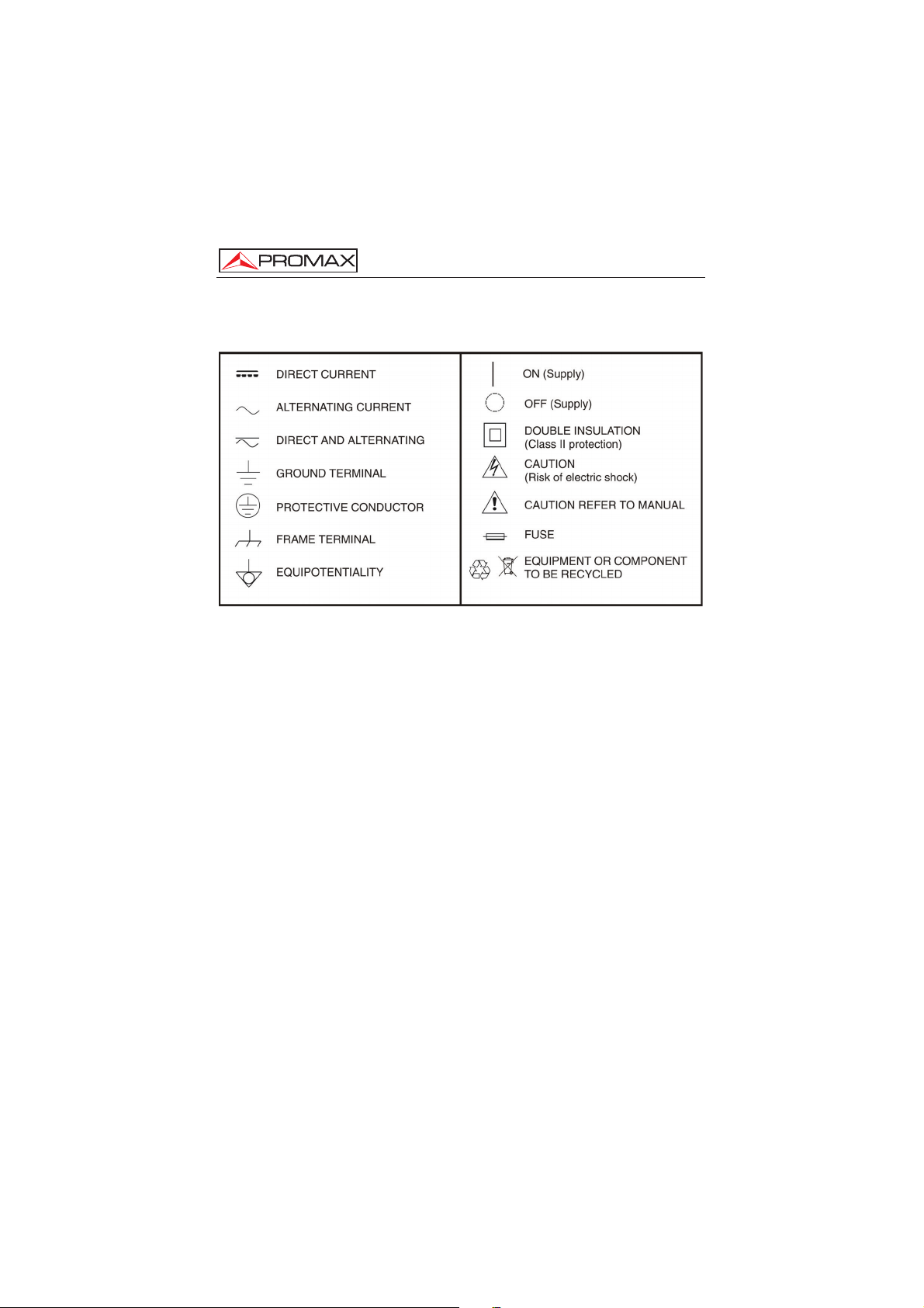
'" Symbols related with safety:
Page 6 10/2010
Page 9

USER’S MANUAL. SATHUNTER+.
English
3. INSTALLATION
3.1 Power Supply
The SATHUNTER+ is a portable instrument powered by a lithium rechargeable
battery. The instrument comes with a mains adapter in order to connect it to the mains
for operation and battery charging.
3.1.1 Operation using the Mains Adapter
Connect the mains adapter to the SATHUNTER+ using the external power
connector
[4] (see Figure 6.-) located on the right side panel. Connect the
adapter to the mains and it will automatically start the battery charging process. The
equipment will emit an acoustic indication. It will also display information about the
battery charging (see “3.1.3 Battery Charging”) on the screen. When the battery is
already charged, the instrument will automatically disconnect. To stop the charging
process, press any of the three keys [1], [2] or [3], for more than 2 s
(the battery-charging screen will disappear).
To start operation, keep any of the three instrument keys ( [1], [2] or
[3]) pressing down for more than 1 s. The instrument will start up. The battery
charging process will stop until the equipment starts up. The charging process will be
slower when the equipment is on.
CAUTION
Before using the mains adapter, make sure that it is the appropriate one for your
mains system: Mains power adapter model AL-101B.
The mains adapter is exclusively designed for indoor use.
3.1.2 Operation Using Batteries
The instrument is powered by a 7.4 V and 2.2 Ah Li-Ion battery.
In order to the equipment works using the battery, you need only press any
instrument key ( [1], [2] or [3]) for more than 1 s. With the battery fully
charged, the SATHUNTER+ has an approximate autonomy of 80 minutes in continuous
operation and at the worst conditions (powering a universal LNB and identifying a
signal).
10/2010 Page 7
Page 10

USER’S MANUAL. SATHUNTER+.
[4] (see Figure 6.-). Then
connect the adapter to the mains. The charging process will start automatically. The
instrument will emit an acoustic indication and the display will show the battery voltage
level, the charge percentage and for how long the battery has been charging.
Figure 1.- Battery charging.
When charging is completed, the instrument is automatically disconnected from
the mains and it will emit two acoustic indications. At the same time the display will
show how long the battery has been charging.
The charging time depends on the state of the battery. If the battery is completely
flat, the charging process will take around 100 minutes. When the battery is fully
charged, the instrument will disconnect automatically. The charging process must be
carry out in a range of temperatures between 5 &C and 40 &C.
IMPORTANT NOTE
At starting the battery charging process and using the instrument for a long
period of time, it could be observed a heating of the instrument. This heating is
normal in the power margin that must be dissipated, according to the battery
charge status and the LNB consumption.
IMPORTANT NOTE
If the equipment is operating and the voltage adapter is connected, the charging
process will be longer. It will depend on the consumption.
When the battery is flat, you will hear an acoustic indication and the screen will
show the message “BATTERY LOW“. Afterwards, if the battery is not charging yet, it
will show the message “VERY LOW BATTERY” and it will emit a warning acoustic
indication. If it is not immediately connected to the mains, the instrument will
automatically switch off.
3.1.3 Battery Charging
To fully charge the battery with the SATHUNTER+ switched off, connect the
mains adapter to the external power supply input
Page 8 10/2010
Page 11

USER’S MANUAL. SATHUNTER+.
English
3.2 Installation and Start-Up
The SATHUNTER+ has been designed for using as a portable instrument.
If you press any key ( [1], [2] or [3]) for one second
approximately, the instrument will start up in “Auto Power OFF” mode. It means that the
instrument will automatically switch off if you do not press any key during 5 minutes. If
you wish to cancel the automatic power off, you have to keep pressing down any key for
five seconds when starting up the instrument, until it appears the message “Manual
Power Off” on the display.
On starting up, you will see the instrument presentation screen (see Figure 2.-).
Figure 2.- Instrument presentation screen.
Next, a screen will display the instrument’s name, company and user names
(editable by software) and the current version of firmware (Figure 3.-).
Figure 3.- Company, name of the equipment and version of firmware.
Finally, it will be shown the Detect function (1> DETECT) screen.
Figure 4.- Detect function screen.
10/2010 Page 9
Page 12

USER’S MANUAL. SATHUNTER+.
The top line of this screen is the same one for all functions of the equipment. Next
it will be explained the icons and messages that can appear depending on the situation.
At the top left corner it is shown the active function. There are three different
options: 1) DETECT, 2) IDENTIFY and 3) ADJUST.
When using the instrument, it may appear on the display some messages and
icons depending on the situation at that time. These are detailed below:
Message Description
"LOW BATTERY"
"VERY LOW BATTERY"
"LNB SHORT CIRCUIT"
"LNB OVER CURRENT"
"MANUAL POWER OFF"
"AUTO POWER OFF"
"SERVICE MODE"
"BATTERY MODE"
"UPDATE MODE"
“NETWORK NOT FOUND”
“SERVICES NOT FOUND”
"LNB NOT DETECTED"
"FULL BATTERY"
"MPEG-2 NOT DETECTED"
"LOADING NETWORK"
"LOADING SERVICES"
"HIGH TEMPERATURE"
-
The equipment will be switched off automatically.
The LNB can be shortcut.
The LNB has a high consumption.
The instrument has to be switched off by hand.
The instrument will switched off after five minutes of
inactivity.
-
-
-
-
-
Power level is below the minimum necessary to detect a
LNB (this value can be adjusted by software, usually
10 %).
-
It is not detecting the Transport Stream signal MPEG-2.
-
-
The running temperature is too high. The equipment must
be switched off for a while. If the problem persists, contact
with the technical support.
Page 10 10/2010
Page 13

USER’S MANUAL. SATHUNTER+.
English
At right corner of the top line, next to the messages, the following icons could be
appear.
Icon Description
Charging battery.
Battery state.
18 / 13 /OFF
LNB power supply. ( 13 V, 18 V or
OFF).
22 KHz signal activated.
, or
The DVB-S, DVB-S2 or DSS has not
been synchronized.
, or
The DVB-S, DVB-S2 or DSS has been
synchronized.
Manual Power Off.
USB
USB connected to the PC.
10/2010 Page 11
Page 14

USER’S MANUAL. SATHUNTER+.
Page 12 10/2010
Page 15

USER’S MANUAL. SATHUNTER+.
English
4. OPERATING INSTRUCTIONS
4.1 Description of the Controls and Elements
Front panel
Figure 5.- Front panel.
[1] DETECT
This key activates the Detect function for the satellite signal. It can also
switch ON the equipment. With a long press on the Detect screen you
access the Setup menu. With a long press on the Identify or Adjust
screen you move to the Test Point 1 (TP1).
[2]
IDENTIFY
This key activates the identification function in order to detect a satellite
and check if is one of the already memorised by the instrument. The
screen shows the 48 first services, the orbital position and the network.
With a short press you go to the next Test Point. With a long press you go
to the previous Test Point. It can also switch ON or OFF the equipment.
10/2010 Page 13
Page 16

ADJUST
This key activates the precision adjustment function in order to adjust
accurately the antenna for optimum signal reception. This function
measures the POWER, LINK MARGIN, MER, CBER, LBER and VBER.
(These last two measures are configurable by software). With a short
press you go to the next Test Point. With a long press you go to the
previous Test Point. It can also switch ON or OFF the equipment.
Side panels
Figure 6.- Side panels.
[4] External 12 V power input.
[5] DATA. USB connector for data transfer, in order to calibrate and configurate the
instrument using a PC.
[6]
RF. RF signal input.
Maximum level 120 dBµV. Universal connector for F/F or F/BNC adapter,
input impedance of 75 .
USER’S MANUAL. SATHUNTER+.
[3]
Page 14 10/2010
Page 17

USER’S MANUAL. SATHUNTER+.
English
4.2 Setup menu
To access the setup menu, from the DETECT screen, press and hold the key
[1] for 1s. approximately until appears the setup screen (Fig. 7.-).
Figure 7.- Setup Menu.
Once inside, to move along the setup menu, press:
CANCEL [1] : To exit the setup menu.
OPTION [2] : To move along the setup options.
SELECT [3] : To move among the available values of a menu option.
Available setup options are:
START SPECTRUM It shows the signal spectrum on the satellite band.
Figure 8.- Function SPECTRUM.
Pressing the key (1) EXIT it returns to the Setup menu.
10/2010 Page 15
Page 18

USER’S MANUAL. SATHUNTER+.
SELECT MEASURE It allows you to select what measurement you want
SOUND CONTROL There are three different options: ON, OFF and BEEP. The
BACKLIGHT MODE Actives (ON) or disables (OFF) the back-light of the screen.
CONTRAST LCD Allow you to chose between four contrast levels.
CONFIRM & EXIT After making changes in the setup menu, you should use
Pressing the key (2) LEVEL it moves the vertical axis of
representation. It moves from 40-70 to 70-100 dB.
Pressing the key (3) LNB it changes the LNB power (13 V,
13 V +22 kHz, 18 V, 18 V + 22 kHz).
displayed on a bar at the screen ADJUST. You can choose
between MER and LM (Link Margin).
option ON emits a sound that varies in tone depending on
the input power and also sounds a beep when pressing a
key. The option OFF does not emit any sound. The option
BEEP, emits a beep every time you press a key but does
not sound the power detector.
The AUTO option actives the back-light when the user is
pressing keys. After one minute without using the
instrument, the back-light turns off.
this option to confirm and apply the values and exit the
setup menu.
4.3 Antenna Adjustment for Optimum Reception
The SATHUNTER+ has been designed to adjust the orientation of a satellite
antenna in order to achieve the optimum reception of a digital satellite signal from a
previously memorised one.
The adjustment process consists of three steps:
1 Satellite detection and location: 1> DETECT
2 Identification of a located satellite: 2> IDENTIFY
3 Precise antenna adjustment for optimum signal quality. 3> ADJUST
Page 16 10/2010
Page 19

USER’S MANUAL. SATHUNTER+.
English
Figure 9.- Valid sequences diagram.
During the whole process the instrument checks the state of the cable, the
connector and the LNB. Therefore, if it detects that the noise level is below a reference
level (standard value: 10 %), it will be shown the message “LNB NOT DETECTED“ at
the bottom of the screen. On the other hand, if the signal power is higher than the
threshold the equipment will emit a variable frequency tone to help the user in order to
position the antenna and detect the maximum signal power.
If the LNB power supply voltage falls 1 V below the nominal value, the instrument
will show the message “LNB SHORTCIRCUIT“ and will temporarily switch off the power
supply to prevent overloads. After one second, the power supply will switch on again,
and it will check if the short circuit has disappeared.
This may occur due to a temporary fall in the voltage when connecting or
disconnecting the instrument from the rest of the installation. The message may also
appear when the power supply is overloaded because of using a LNB with excessive
consumption.
4.3.1 Satellite Detection and Location (1> DETECT)
This function is directly accessed on starting the instrument. If it is not the active
function, press key
[1] to select it.
The purpose of this function is to detect when the antenna is pointing at a satellite
(detection).
In order to do this, connect the instrument to the low-noise amplifier that is located
at the focus of the parabolic antenna. On the screen you will see two horizontal bars
that can vary depending on the power signal. The upper horizontal bar keeps the
maximum value measured during tracking. The lower horizontal bar shows the signal
power in real time. In addition to these bars, there is an audible signal that varies
depending on the power signal, from low tone (low power) to high tone (high power).
10/2010 Page 17
Page 20

USER’S MANUAL. SATHUNTER+.
Figure 10.- DETECT function.
If no signal is detected, the display will show horizontal bars at minimum level and
the percentage of power rate at 0 %. There will not be either audible signal and it will
appear the message “LNB NOT DETECTED”.
4.3.2 Satellite Identification (2 > IDENTIFY)
Once a satellite has been detected (by localising a power maximum), you should
check if the received signal corresponds to anyone of the memorised satellites. Select
the satellites identification function 2> IDENTIFY by pressing key [2].
The identification system is based on a database of satellites previously loaded to
the equipment. Consult the configuration sheet supplied with the instrument for further
information on satellites that the instrument can detect.
The instrument can memorise up to fifty combinations of frequencies and
polarizations (50 test points).Frequency measurements are configurable by software.
They can be shown as a FR (intermediate frequency) or DL (Downlink frequency). The
number of active points (selectable) can be also configured. A greater or lesser number
of satellites can be identified depending on the number of active points and how many
you want to assign to each satellite. Therefore, for example, if we assign one frequency
and the two possible polarizations to each satellite (i.e. 2 points for each satellite) and
they are activated 14 points, the instrument will be able to identify a total amount of 7
satellites. See the configuration sheet delivered with the instrument for further
information. Each test point has a name up to 8 letters assigned to it. It will be shown on
the display when is selected.
Figure below shows the display of SATHUNTER+ in detect mode. Among the
data shown, there is the voltage average supplied to the LNB and if it is being applied
the 22 kHz signal.
Page 18 10/2010
Page 21

USER’S MANUAL. SATHUNTER+.
English
Note: We advise to assign two test points to each satellite, the first one with
vertical polarization and the second one with horizontal polarization in
order to guarantee the identification of the satellite.
The key [2] enables you, as you can see at figure 11, to change the selected
test point in a sequential way. Each time you press shortly this key it advances to the
next test point. If you press longer (1 s.) this key it goes back to the previous test point.
If you want to go to the first test point (TP1) you should press the key
[1] for 1 s.
Figure 11.- Rotation of active test points.
When you select a satellite test point, the name (four letters maximum) and
frequency assigned to that point is displayed.
Figure 12.- Satellite identification screen.
Afterwards, if it is detected a signal with a valid transport stream at the frequency
(or frequencies) assigned to this satellite, the instrument will show at the top right corner
the symbols DVB-S, DVB-S2 or DSS depending on the selected
transport stream. Additionally it will attempt to obtain, the Network, the first 48 services
and the orbital position of the satellite the antenna is pointing at. When this information is
detected, it will be shown on the display. Sometimes this could cause a reduction in the
amount of identifying text characters.
NOTE: For DSS, the TS information is not available.
10/2010 Page 19
Page 22

USER’S MANUAL. SATHUNTER+.
, or symbol at the top
right corner and the name of the test point memorised. If later on, the equipment
achieves to synchronize, it will update the services list and the colour of the symbol
shown will change to
, or .
4.3.3 Antenna Adjustment for Optimum Signal Quality (3> ADJUST)
Once the antenna has been positioned in order to receive the maximum power
and you have checked that the antenna is pointing the right satellite, the antenna and
the LNB have to be adjusted to achieve the maximum MER level, and therefore the best
quality at reception.
The adjustment (ADJUST) function shows the information regarding the signal
quality. You should select the 3> ADJUST function pressing the key [3]. When it
detects a signal with a valid transport stream, the SATHUNTER + shows briefly the
network name and orbital position at the top line of the screen. When it is locked to the
signal, it shows the symbol , or depending on the satellite signal
detected. This function measures the ratio between the DVB average power and the
noise average in a constellation (MER). It also measures the error rate in a DVB signal,
before the correction process (CBER). Once all the measurements are done
(approximately after 5 s), they will be displayed on the screen in a graphical and
alphanumerical way (see figure 13). At the top line of the screen it keeps displaying the
battery level, the measured LNB voltage and whether the 22 kHz signal is present or
not.
Figure 13.- Adjust function screen.
ATTENTION
The signal provider is the exclusive responsible in the accuracy of the orbital
position. PROMAX ELECTRONICA, S.A. only extracts and shows the information
contained in the detected signal.
At first, it could be that the equipment could not detect a signal with a valid
transport stream and therefore it will appear the
Page 20 10/2010
Page 23

USER’S MANUAL. SATHUNTER+.
English
Measure units of power can be configured by software. Available values are:
dB#V, dBmV or dBm.
The LINK MARGIN function (LM) measures the reception quality of the data link
(in dBs) between the satellite and the receiving antenna. A positive value indicates the
signal is correct. The higher the value, the greater the operating margin for future
adverse conditions. A zero value indicates it is about to lose the link. Negative values
means pixelaciones or signal loss.
Once the antenna is well positioned, if you wish to measure the MER on other
transponders of the same satellite that are memorised in the instrument, you can
change the test point by pressing the key
[3] until you select the right one. If you
wish to measure the MER for other satellites memorised in the instrument, before that
you have to orientate correctly the antenna and then, change satellite pressing the key.
[3]. The variation between satellites and transponders depends on how you set the
table of channels loaded into the SATHUNTER+.
In addition, the SATHUNTER+ can measure the VBER for DVB-S or DSS and
the LBER for DVB-S2 (see figures 14 and 15). In order to do this, the SATHUNTER+
should be configured using the PROMAX software.
Figure 14.- DVB-S measurements with VBER.
Figure 15.- DVB-S2 measurements with LBER.
10/2010 Page 21
Page 24

USER’S MANUAL. SATHUNTER+.
[2] or [3]
for more than two seconds.
4.4 Instrument Configuration
The various parameters and information stored in the SATHUNTER+ can be
modified using the PC program “CONFIGURATION SOFTWARE FOR
SATHUNTER+”. This program is supplied with the instrument.
The program allows you to define the number of test points, the different
parameters for each point and the user and company’s name.
Once the instrument has been configured, it has to be rebooted in order to apply
the changes.
All the necessary information for configuring the instrument and for using the
“CONFIGURATION SOFTWARE FOR SATHUNTER+” program can be found in the
manual accompanying the program.
CONTROL PROGRAM (PC)
NOTE:
To update the software version and user’s manual access the PROMAX web page:
www.promaxelectronics.com
As time goes by, the DVB-S, DVB-S2 and DSS demodulator circuit tends to
measure better, due to it includes an input signal tracking and an adaptation algorithm.
Therefore, to ensure a good quality at reading signal, you should wait for some additional
measurements.
If moving the antenna the MER value exceeds the quality reference (configurable
by software), the instrument will emit a high-pitched audible signal and the word MER
will become bold (MER). If the MER value is below the quality reference then the
instrument will emit a low-pitched audible signal and the word “MER” will not change.
Note: For the final step of precise adjustment and the optimisation of the signal
quality, it is important to select the most critical test point. This will
guarantee the quality for the other points with better conditions.
To switch off the instrument, press any of the instrument keys
Page 22 10/2010
Page 25

USER’S MANUAL. SATHUNTER+.
English
5. MAINTENANCE
CAUTION
The battery used can present danger of fire or chemical burn if it is severely
mistreat.
Do not disassembly, cremate or heat the battery above 100
&
C under no
circumstances.
5.1 Cleaning Recommendations
CAUTION
To clean the cover, take care the instrument is disconnected
CAUTION
Do not use scented hydrocarbons or chlorized solvents. Such products may
attack the plastics used in the construction of the cover.
The cover should be cleaned by means of a light solution of detergent and water
applied with a soft cloth.
Dry thoroughly before using the equipment again.
CAUTION
Do not use alcohol or its derivates for the cleaning of the front panel and
particularly the viewfinders. These products can attack the mechanical properties
of the materials and diminish their useful time of life.
5.2 Fuses
Fuses not replaceable by the user.
F001: FUS SMD 2,5 A T 125 V.
10/2010 Page 23
 Loading...