

Page 1
Refrigerant Recovery Machine
TM
RG6000
Operating Manual
Manuel d’utilisation
Bedienungsanleitung
Manual de operaciones
1
Page 2
Sa f e t y Pr e c a u t i o n S
WARNING : TO PREVENT PERSONAL INJURY AND / OR EQUIPMENT DAMAGE,
ALLOW ONLY QUALIFIED PERSONNEL TO OPERATE THIS UNIT. Before operating the unit,
read and follow the instructions and warnings in this manual. The operator must be familiar with air
conditioning and refrigeration systems, refrigerants, and the dangers of pressurized components. If
the operator cannot read this manual, operating instructions and safety precautions must be read and
discussed in the operator’s native language.
PRESSURIZED TANK CONTAINS LIQUID REFRIGERANT. Do not overll storage vessels, because
overlling may cause explosion and personal injury or death. Do not recover refrigerants into nonrellable containers; use only federally authorized rellable containers (DOT spec. 4BW or 4BA).
HOSES MAY CONTAIN LIQUID REFRIGERANT UNDER PRESSURE. Contact with refrigerant may
cause personal injury. Wear protective equipment, including safety goggles and protective gloves.
Disconnect hoses using extreme caution.
DO NOT BREATHE REFRIGERANT AND LUBRICANT VAPOR OR MIST. Exposure may cause
personal injury, especially to the eyes, nose, throat, and lungs. Use the unit in locations with mechani-
cal ventilation that provides at least four air changes per hour. If accidental system discharge occurs,
ventilate the work area before resuming service.
USE THE SHORTEST POSSIBLE EXTENSION CORD WITH A MINIMUM SIZE OF 14 AWG. Using
an undersized extension cord may result in electrical equipment failure.
TO REDUCE THE RISK OF FIRE, do not use the unit in the vicinity of spilled or open containers of
gasoline or other ammable substances.
DO NOT USE COMPRESSED AIR TO PRESSURE TEST OR LEAK TEST THE UNIT OR AIR
CONDITIONING SYSTEM. Some mixtures of air and R-134a refrigerant are combustible at elevated
pressures. These mixtures are potentially dangerous and may result in re or explosion causing personal injury or property damage.
DO NOT MIX REFRIGERANT TYPES THROUGH A SYSTEM OR IN THE SAME CONTAINER. Mix-
ing of refrigerants will cause severe damage to the unit and the system being serviced.
HIGH VOLTAGE ELECTRICITY INSIDE THE UNIT HAS A RISK OF ELECTRICAL SHOCK. Exposure may cause personal injury. Disconnect power before servicing the unit.
Ex p l a n a t i o n o f Sa f E t y Si g n a l Wo r d S
WARNING : Indicates a potentially hazardous situation which, if not avoided, could result in death or
serious injury.
CAUTION : Indicates a potentially hazardous situation which, if not avoided, may result in minor or
moderate injury.
CAUTION : Used without the safety alert symbol indicates a potentially hazardous situation which, if not
avoided, may result in property damage.
2
Page 3

ta b l e o f co n t e n t S
Understanding Refrigerant Recovery . . . . . . . . . . . . . . . . . . . . . . . .4
Standard Operating Instructions . . . . . . . . . . . . . . . . . . . . . . . . . . .5
Setup . . . . . . . . . . . . . . . . . . . . . . . . . . . . . . . . . . . . .5
Recovery Procedure . . . . . . . . . . . . . . . . . . . . . . . . . . . . . 6
Purge the RG6000 Unit. . . . . . . . . . . . . . . . . . . . . . . . . . . . 6
Operating Instructions for Bulk Liquid Systems . . . . . . . . . . . . . . . . . . .7
Push – Pull Procedure . . . . . . . . . . . . . . . . . . . . . . . . . . . . 7
Liquid Recovery. . . . . . . . . . . . . . . . . . . . . . . . . . . . . . . . 7
Vapor Recovery . . . . . . . . . . . . . . . . . . . . . . . . . . . . . . . . 8
Purge Non-Condensable Gas from a Storage Cylinder . . . . . . . . . . . . . . . 8
Recovery Cylinder Information. . . . . . . . . . . . . . . . . . . . . . . . . . . .9
Troubleshooting . . . . . . . . . . . . . . . . . . . . . . . . . . . . . . . . . . 10
Replacement Parts. . . . . . . . . . . . . . . . . . . . . . . . . . . . . . . . . 11
Rebuild Kits and Accessories . . . . . . . . . . . . . . . . . . . . . . . . . . . 12
Maintenance . . . . . . . . . . . . . . . . . . . . . . . . . . . . . . . . . . . . 13
Installation of the Filter and Filter / Drier . . . . . . . . . . . . . . . . . . 13
Burned-out System . . . . . . . . . . . . . . . . . . . . . . . . . . . . . 13
Storage . . . . . . . . . . . . . . . . . . . . . . . . . . . . . . . . . . . 13
Safety Precautions . . . . . . . . . . . . . . . . . . . . . . . . . . . . . . . . . .2
Explanation of Safety Signal Words . . . . . . . . . . . . . . . . . . . . . . . . .2
Warranty Statement . . . . . . . . . . . . . . . . . . . . . . . .Inside Back Cover
3
Page 4
un d e r S t a n d i n g re f r i g e r a n t re c o v e r y
Refrigerant recovery is the processs of taking refrigerant
out of a system and storing it in a cylinder. The following
information is critical to achieving the best refrigerant
recovery results.
Refrigerant
Identify the refrigerant type and quantity in the system to
be serviced.
The RG6000 unit is approved for use with the following
category III, IV, and V refrigerants (per ARI-740) :
R-12, R-22, R-134a, R-401a, R-401b,R-401c, R-402a,
R-402b, R-404a, R-406a, R-407a, R-407b, R-407c,
R-407d, R-408a, R-409a, R-410a, R-411a, R-411b,
R-412a, R-500, R-502, R-507 R-509
Filters and Filter / Driers
CAUTION : Filters prevent contamination from entering
the unit, which reduces the risk of damage to the unit
and the system being serviced.
The RG6000 unit is shipped with a lter screen installed
behind the inlet tting. Promax strongly recommends that
a clean lter screen be used for every service job. Failure
to use a lter screen will invalidate your warranty.
Promax also strongly recommends using a lter / drier
(part no. 100343; not provided) at the inlet tting. Each
in-line lter / drier must be labeled and used for only one
type of refrigerant.
Valves
WARNING : To prevent personal injury, open
service and cylinder valves SLOWLY to allow
rapid shut-off of gas flow if necessary. Once it is
determined there is no danger, the valves may be
opened fully.
Isolate large amounts of refrigerant and close valves
after use, so if a leak should develop anywhere in the
system, refrigerant will not escape to the atmosphere.
Storage Cylinders
WARNING : A storage cylinder is full when it
reaches 80% volume. DO NOT OVERFILL. Due to
liquid expansion, the cylinder could explode if filled
to more than 80% volume, possibly causing personal
injury and equipment damage. Use a scale, such
as the TIF9010A, to avoid overfilling the storage
cylinder.
Promax recommends using the optional 80% Capacity
Shutoff Kit (p/n SK-5001) with this unit. After the kit is
installed and used with a recovery cylinder having an
internal oat switch, the unit automatically shuts down
when the cylinder is 80% full. (Your unit is pre-wired at
the factory for this kit.)
Hoses
Hoses must be equipped with low-loss ttings and have
pressure ratings appropriate for the refrigerant in the
system being serviced.
Shut-off Switch
This unit has an internal, high-pressure, shut-off switch.
If system pressure rises above 550 psi, the unit shuts
off. The shut-off switch automatically resets itself after
pressure drops below 400 psi.
WARNING : The internal pressure shut-off
switch does NOT prevent cylinder overfill. If the
system shuts off automatically and is connected
to a cylinder, the cylinder may be dangerously
overfilled. Take immediate measures to relieve the
high pressure and / or cylinder overfill situation, or
personal injury may result.
Push / Pull Procedure
When recovering large amounts of liquid (over 15 lbs.),
use the Push / Pull method described in this manual.
Maximum Vacuum and Recovery Rates
To achieve the deepest nal vacuum, use an evacuated
recovery cylinder. To maximize recovery rates :
Use the shortest possible length of 3/8" or larger hose.
•
(A hose no longer than 3 feet is recommended.)
Remove unnecessary hose core depressors, and
•
remove Schrader valves from port connections.
Deformed rubber seals and core depressors in hoses,
as well as faulty or unnecessary Schrader valves, can
restrict ow.
If you are certain the refrigerant in the system being
•
serviced is clean or new, the lter screen may be
removed from the inlet tting.
Purge the RG6000 during the end of the vapor
•
recovery phase, especially when recovering large
amounts of vapor. Purge again after the recovery
process is complete and the desired vacuum has been
achieved. Refer to “Purge the RG6000 Unit” at the end
of the Standard Operating Instructions section.
Maintenance
CAUTION :
system dry and clean. Damage will occur if moisture
is allowed to enter the system.
Keep all connections to the refrigeration
4
Page 5
St a n d a r d oP e r a t i n g in S t r u c t i o n S
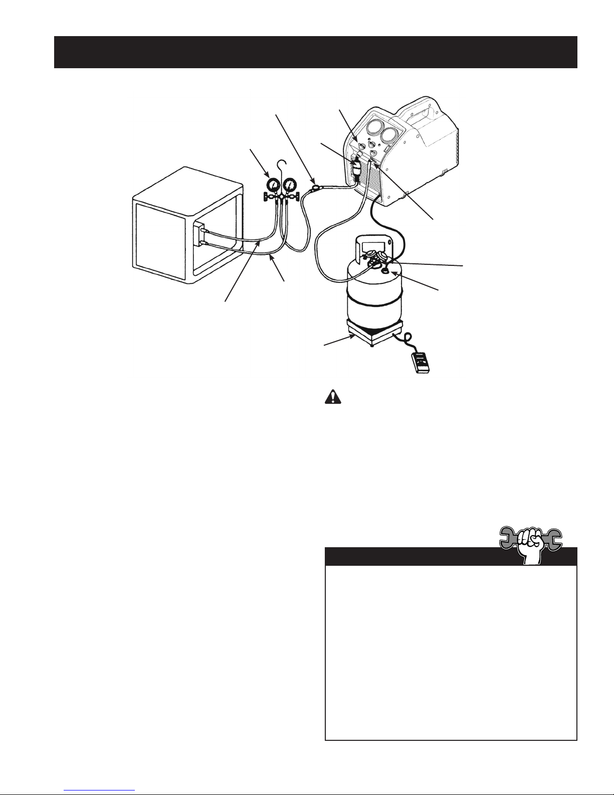
Sight
Glass
Manifold
Gauge Set
System Being
Serviced
Liquid
Vapor
The following instructions are for a standard or
“common” recovery procedure.
Setup Procedure
1. Place the RG6000 unit on a at, level surface.
2. Verify a clean lter screen is installed behind
the inlet tting.
Inlet
Fitting
Filter / Drier
Scale
WARNING : A storage cylinder is full when
it reaches 80% volume. DO NOT OVERFILL. Due
to liquid expansion, the cylinder could explode
if lled to more than 80% volume, possibly
causing personal injury and equipment damage.
Recovery
Cylinder
Outlet
Fitting
Liquid Port
Float Switch
Connection
(RG6000-KT only)
3. Connect a hose from the outlet tting of the
unit to the liquid port on the recovery cylinder.
4. Connect a hose from the inlet tting of the unit
to the output port of a manifold gauge set.
Promax recommends using a sight glass and a
lter / drier in this line.
5. Connect a hose from the liquid (low pressure)
side of the manifold gauge set to the liquid side
of the system being serviced.
6. Connect a hose from the vapor (high) side of
the manifold gauge set to the vapor side of the
system being serviced.
RG6000-KT only: Attach tank connection
harness (No. 549977) to oat switch
connection on the recovery cylinder.
7. Verify the inlet and outlet valves on the
RG6000 unit are closed.
8. Place the recovery cylinder on a scale (such as
TIF9010A) to avoid overlling the cylinder.
Tech Tips
The RG6000 will perform at its peak when voltage
entering the machine (while operating) is between
115V AC and 122V AC. Lower supply voltages
may result in difculty starting under high head
pressure, reduced performance, and / or motor
overheating.
Use an outlet that does not have other applicances
(such as lights, machines, etc.) plugged into it.
Do not use an extension cord unless needed. If
an extension cord is used, it must be 14 AWG
minimum and as short as possible to reduce
voltage drops.
5
Page 6

St a n d a r d oP e r a t i n g in S t r u c t i o n S
Recovery Procedure
1. Connect the unit to a 115V outlet.
2. Slowly open the liquid valve of the recovery
cylinder while watching hoses and connections
for leaks.
3. Set the recover / purge valve on the RG6000
unit to RECOVER.
4. Open the liquid valve on the manifold gauge
set. Note: Opening the liquid valve removes
liquid from the system rst, greatly reducing
recovery time.
5. Open the outlet valve on the RG6000 unit.
6. Toggle the power switch to the ON position.
7. Slowly open the inlet valve on the unit. Note: If the unit begins to “knock”, slowly throttle back (close)
the inlet valve until the noise stops.
8. Once the liquid has been removed from the system, open the vapor valve on the manifold gauge set to
nish evacuating the system.
9. Run the RG6000 until the desired vacuum is achieved.
10. Close the vapor and liquid valves on the manifold gauge set.
11. Turn the inlet valve on the RG6000 to the CLOSED position.
12. Toggle the power switch OFF.
Purge the RG6000 Unit
CAUTION : Always purge the RG6000 unit after
a recovery procedure. Failure to purge the
remaining refrigerant from the unit could result
in acidic degradation of internal components,
ultimately causing premature failure of the unit.
1. Verify the liquid and vapor valves on manifold
gauge set are closed (if applicable).
2. Close the valves on the system being serviced
(if applicable).
3. Verify the outlet valve on the unit is open and
the inlet valve is closed.
4. Verify the liquid valve on the recovery cylinder
is open.
5. Turn the recover / purge valve to the PURGE
position.
6. Toggle the power switch ON.
7. Slowly turn the inlet valve toward the PURGE
position. As the inlet side pressure decreases,
open the valve to the full purge position.
8. Run the unit until the desired vacuum is
achieved.
9. Close the inlet and outlet valves on the unit.
10. Toggle the power switch OFF.
11. Close the ports on the recovery cylinder.
12. Turn the recover / purge valve to the
RECOVER position.
13. Disconnect all accessories and replace the inline lter.
If you have trouble starting or re-starting the unit
due to high head pressure, rst close the inlet
valve. Then slowly turn the inlet valve toward the
purge position until the inlet pressure rises. Close
the inlet valve again and re-start the unit.
Tech Tip
6
Page 7

oP e r a t i n g in S t r u c t i o n S f o r bu l k li q u i d Sy S t e m S
“Push – Pull” Procedure
The push – pull method removes bulk liquid from a system using the pressure differential created by the
recovery machine. This method works only with large systems where the liquid is readily accessible; it may
not work on systems that contain less than 15 lbs. bulk liquid.
This method is used :
on systems with receiver cylinders.•
on systems containing more than 20 lbs. of refrigerant.•
when transferring bulk liquid refrigerant from one cylinder to another.•
Liquid Recovery
1. Place the RG6000 unit on a at, level surface.
2. Connect a hose from the outlet tting of the unit
to the vapor port on the system being serviced.
3. Connect a hose from the inlet tting of the unit
to the vapor port of a recovery cylinder. Promax
recommends using a lter / drier in this line.
4. Connect a hose from the liquid side of the
recovery cylinder to the liquid port of the
system being serviced. Promax recommends
using a sight glass in this line as a method of
determining when the liquid has been removed.
RG6000-KT only: Attach tank connection
harness (No. 549977) to oat switch connection
on the recovery cylinder.
5. Place the recovery cylinder on a scale (such as
TIF9010A) to avoid overlling the cylinder.
Filter/Drier
System Being
Serviced
6. Verify inlet and outlet valves on unit are closed.
7. Turn the recover / purge knob to RECOVER.
8. Open the recovery cylinder valves.
9. Open the outlet valve on the unit.
10. Toggle the power switch ON.
11. SLOWLY open the inlet valve on the unit.
12. When the weight reading on the scale stops
increasing, close the inlet valve on the unit
rst; then close the liquid valve on the recovery
cylinder.
13. Toggle the power switch OFF.
14. Close the valves on the recovery cylinder, and
close the outlet valve on the machine.
15. Proceed to Vapor Recovery.
Inlet
Fitting
Outlet Fitting
WARNING : Manually close the valves on both
the storage cylinder and the RG6000 unit to prevent
overfilling the cylinder. Once the siphon is started, it
can overfill the storage cylinder, even if the cylinder
is equipped with a float level sensor. The siphon can
continue even when the machine is turned off.
Vapor
Liquid
7
Sight
Glass
Scale
Vapor
Recovery
Cylinder
Liquid
Float Switch
Connection
(RG6000-KT only)
Page 8

oP e r a t i n g in S t r u c t i o n S f o r bu l k li q u i d Sy S t e m S
Vapor Recovery
1. Place the RG6000 unit on a at, level surface.
2. Connect a hose from the inlet side of the unit to
the liquid port of the system being serviced.
Tech Tip
3. Connect a hose from the outlet side of the unit
to the liquid port on a recovery cylinder.
CAUTION: The recovery cylinder should be
on a scale to avoid overlling the cylinder.
4. Open the liquid valve on the recovery cylinder.
5. Turn the recover / purge knob to RECOVER.
6. Open the outlet valve on the unit.
7. Toggle the power switch ON.
8. Slowly open the inlet valve on the unit.
9. Run the unit until the desired vacuum is
achieved.
10. Close the inlet and outlet valves on the unit.
11. Toggle the power switch OFF.
12. Close the ports on the recovery cylinder.
For a faster recovery procedure, recover from both
the liquid and vapor ports of the system being
serviced by using a tee tting or manifold gauge
set in the hose setup.
Pu r g e no n -co n d e n S a b l e ga S f r o m a St o r a g e cy l i n d e r
1. Allow the storage cylinder to sit undisturbed for
24 hours to allow air to rise to the top.
2. Connect a manifold gauge set to the cylinder.
Read the amount of pressure in the cylinder as
indicated by the output pressure gauge.
3. Determine the ambient temperature in the
room.
4. Refer to a refrigerant pressure/temperature
chart and nd the ambient temperature. Read
across the chart to the corresponding pressure
for the type of refrigerant in the cylinder.
Determine how that relates to the reading on
the gauge.
5. If the pressure reading in the cylinder is
higher than the pressure shown on the chart,
VERY SLOWLY crack open the vapor port
valve. (This is done slowly to cause as little
turbulence inside the cylinder as possible.)
Watch the pressure on the gauge decrease.
To prevent venting, add 4–5 psi to the
pressure shown on the chart.When the gauge
corresponds to that pressure, close the vapor
port valve.
6. Allow the cylinder to sit for 10 minutes and then
check pressure again.
7. Repeat the process, if necessary.
8
Page 9

re c o v e r y cy l i n d e r in f o r m a t i o n
Type of Cylinder
Use only authorized, rellable, refrigerant storage
cylinders. Federal regulations require refrigerant
to be transported only in containers meeting DOT
specs. 4BW or 4BA.
NEVER use a standard disposable 30 lb. cylinder
(the type of container in which new refrigerant is
sold) to recover refrigerant.
Working Pressure
Recovery cylinders are designed for different
working pressures. PROMAX strongly recommends
the use of 400 psi cylinders.
WARNING: To prevent personal injury, do
not exceed the rated working pressure of the
cylinder. At minimum, the RG6000 requires the
use of a 350 psi recovery cylinder.
NOTE: The use of a 400 psi cylinder is mandatory
when recovering R-410A refrigerant. Refer to the
Parts and Accessories section of this manual for
more information.
If you expect temperatures in excess of 135º F,
consult the refrigerant supplier.
Capacity
Safety codes state that closed cylinders should
not be lled with liquid over 80% of volume. (The
remaining 20% is called head pressure room.)
Do not exceed 80% of cylinder capacity. PROMAX
recommends the use of the TIF9010A Refrigerant
Scale for monitoring cylinder capacity.
Refrigerants
Cylinders and lter / driers should each be
designated for only one type of refrigerant.
If you must use a cylinder previously used for
a different refrigerant, prepare the cylinder by
completely emptying it, perform an evacuation,
purge it using dry nitrogen, and then perform
another evacuation.
Storage
Store refrigerant cylinders in a cool, dry place.
Leakage
Some cylinders have valves that were not correctly
seated when manufactured. Keeping caps on the
valves will guard against refrigerant leakage.
WARNING : To prevent personal injury, never transport an overfilled cylinder.
Refrigerant expands when it gets warm and may cause an overfilled cylinder to explode.
Storage Cylinder Temperature 60°F 70°F 100°F 130°F 150°F
STARTING WITH CYLINDER
80% BY VOLUME
Space Occupied by Liquid 80% 81% 83% 90% 94%
STARTING WITH CYLINDER
90% BY VOLUME
Space Occupied by Liquid 90% 92% 96% 100%
9
Page 10

tr o u b l e S h o o t i n g
WARNING: TO PREVENT PERSONAL INJURY AND / OR EQUIPMENT DAMAGE,
ALLOW ONLY QUALIFIED PERSONNEL TO OPERATE AND REPAIR THIS UNIT. Before operating
or repairing the unit, read and follow the instructions and warnings in this manual. The technician must
be familiar with air conditioning and refrigeration systems, refrigerants, and the dangers of pressurized
components. If the technician cannot read this manual, operating instructions and safety precautions
must be read and discussed in the technician’s native language.
Symptom Possible Cause Possible Solution
Unit will not turn on 1. Power cord not plugged in.
2. Bad power outlet.
3. Machine is in high-pressure shut-off.
4. Motor is in thermal overload.
5. Circuit breaker tripped.
Compressor tries to
start, but just buzzes
Machine pumps into
high-pressure shut-off
Slow recovery 1. Trapped liquid in system.
Circuit breaker trips 1. Low voltage at power source.
1. Low voltage at power source.
2. Extension cord too long, or too
small.
3. Head pressure too high.
1. Output valve on machine is closed.
2. Recovery cylinder valve closed.
3. Head pressure too high.
2. Restriction in refrigerant ow path.
2. Extension cord too long, or too
small.
3. Excessive load on compressor /
motor.
1. Check power cord at wall and unit.
2. Try a different outlet.
3. Reduce head pressure to below
400 psi.
4. Allow motor / unit to cool down.
5. Check / reset circuit breaker.
1. Locate / use better outlet.
2. Reduce length of extension cord.
Increase size (gauge) of extension
cord (14 AWG minimum).
3. Reduce head pressure. Turn inlet
valve slightly past closed toward
PURGE to equalize high-side / low side pressure.
1. Check output valve.
2. Check recovery cylinder valve.
3. Check output hoses for restrictions
or kinks. Reduce head pressure.
1. Momentarily cycle system compressor
to move trapped refrigerant.
2. Check inlet hose for restrictions or
kinks. Remove Schrader valves and
core depressers from hoses (if
possible). Use larger hoses.
1. Locate / use better outlet.
2. Reduce length of extension cord.
Increase size (gauge) of extension
cord (14 AWG minimum).
3. Reduce head pressure. Throttle inlet
valve to reduce load on compressor.
10
Page 11

13
14
15
re P l a c e m e n t Pa r t S
1 (left side shown)
2
Motor Relay
& Capacitor
16
17
18
}
6
7
Divider
3
4
Motor Interface
5
Counterbalance
11
10
12
9
Item Part
No. No. Qty. Description
1 550495 1 Case Half (left)
550496 1 Case Half (right)
2 550503 1 Grommet (1 ea.)
3 SK-6013 1 Motor Clamp Kit (4 pieces)
4 SK-6005 1 Motor Kit (includes motor, relay,
capacitor, hardware)
5 SK-6017 1 Compressor Kit (includes
compressor, cover, hardware)
6 Sk-6008 1 Fan Kit (includes fan, spacer
mounting hardware)
7 GA1000 1 Gauge Lens (1 ea.)
8 100124 1 Manifold Knob (red)
9 100123 1 Manifold Knob (blue)
10 100122 1 Manifold Knob (black)
11 SK-6014 1 Condenser Kit (includes condenser
assembly, hardware)
19
Inlet / Outlet
Tubes
RG6000-KT
only
8
Item Part
No. No. Qty. Description
12 551628 1 Power Cord
13 SK-6012 1 Bezel Kit (includes bezel, power
switch, circuit breaker, power entry
module, hardware)
14 SK-6001 1 Inlet Fitting / Filter Screen Kit
(includes inlet tting, lter screen,
o-ring)
15 550502 1 Foot (1 ea.)
16 SK-6003 1 Low-side Gauge Kit (includes
low-side gauge, lens)
17 SK-6022 1 High-side Gauge Kit (includes
high-side gauge, lens)
18 SK-6016 1 Manifold Kit (includes manifold
assembly, hardware)
19 549977 1 Tank Connection Harness
(RG6000-KT only)
11
Page 12

re b u i l d ki t S a n d ac c e S S o r i e S
Part
No. Description
SK-5001 80% Tank Shut-off Kit
SK-6001 Filter Screen Replacement Kit
SK-6002 Filter / Drier Kit (includes lter / drier, 6 inch hose)
SK-6005 Motor Replacement Kit
SK-6006 Compressor Rebuild Kit (includes piston seals, valves, springs, o-rings)
SK-6007 Valve Rebuild / Replacement Kit (includes inlet /oulet valves and springs, o-rings)
SK-6008 Fan Replacement Kit
SK-6012 Bezel Replacement Kit
SK-6014 Condenser Replacement Kit
SK-6015 Piston Seal Rebuild Kit (includes piston seals, energizer o-ring, wear bands)
SK-6016 Manifold Replacement Kit
SK-6017 Compressor Replacement Kit
SK-6022 Gauge Replacement Kit
TIF9010A Refrigerant Scale
17572 Recover Cylinder (50 lb. capacity, 400 psi working pressure, capacity sensor)
12
Page 13

ma i n t e n a n c e
CAUTION : To prevent personal injury, disconnect the RG6000 from the power supply before
performing maintenance.
Installation of the Filter and Filter / Drier
1. Before performing a refrigerant recovery, always inspect and clean the filter screen in the inlet fitting on
the RG6000 unit. Replace the filter screen (p/n SK-6001) if necessary. A filter screen greatly reduces
the risk of damage to the unit by preventing foreign material from entering the unit and the system
being serviced. Failure to use a filter screen will invalidate the warranty.
Promax also strongly recommends using an in-line filter / drier (p/n 100343) in the inlet line.
Filter
Screen
Inlet
Fitting
Filter /Drier
p/n 100343
Burned-out System
1. Use two high-acid capacity lter / driers in series when recovering from a “burned-out” system. Promax
recommends Alco type EK-162-F or Sporlan type C-162-F lters.
When you have nished recovering from the system, ush the RG6000 with a small amount of clean
refrigerant and refrigerant oil to purge any foreign substances left in the unit.
Storage
1. Empty refrigerant from the unit into a storage cylinder. Liquid refrigerant left in the unit’s condenser may
expand, causing damage to components.
2. Completely evacuate the RG6000 of any residual refrigerant and purge it with dry nitrogen before
putting it in storage for a long period of time.
13
Page 14

fu l l on e -ye a r li m i t e d wa r r a n t y
ei n j ä h r i g e ga r a n t i e
Unit Serial No.
This product is warranted to be free from defects in workmanship, materials and
components for a period of one year from date of purchase.
The following restrictions apply:
1. This warranty is non-transferable. All warranty claims must be made within the
warranty period. Proof of purchase must be supplied with the product when returned.
2. The warranty applies to product in normal use only, as described in this operating
manual. The product must be maintained and serviced as specied.
3. If the product fails, it will be repaired or replaced at the option of the manufacturer
(SPX). Warranty service claims are subject to factory inspection for product defects.
The manufacturer is the sole determiner of warranty coverage. If during the warranty
evaluation it is determined that proper maintenance was not performed, or that the
product has been used in any way other than the purpose for which it was designed,
the manufacturer reserves the right to void the warranty.
4. Normal wear items (seals, lters, etc.) are specically excluded from this warranty,
unless found by the manufacturer to be defective.
This warranty does not apply if the product or product part is damaged by accident, misuse,
tampering with, or modifying in anyway. The manufacturer is not responsible for any
additional costs associated with a product failure including, but not limited to, loss of work
time, loss of refrigerant, or unauthorized shipping and/or labor charges.
Use of this product with any unauthorized refrigerants or chemicals will void the warranty.
Warranty Service:
1. Outside of the United States of America, contact your local Promax distributor.
2. Inside the United States of America, call 1-800-327-5060 for a Return Material
Authorization (RMA) number. Instructions on where to send the product will be
provided.
Serien-Nr. des Geräts
Es wird garantiert, dass dieses Produkt während des Zeitraums von einem Jahr ab Kaufdatum
frei von Material-, Komponenten- und Verarbeitungsfehlern ist.
Es gelten folgende Beschränkungen:
1. Diese Garantie ist nicht übertragbar. Alle Garantieansprüche müssen innerhalb der
Garantieperiode eingereicht werden. Beim Umtausch muss der Kaufbeleg vorgelegt
werden.
2. Diese Garantie gilt für ein Produkt, das gemäß den Anweisungen in dieser
Bedienungsanleitung verwendet wurde. Das Produkt muss gemäß den
Anweisungen gewartet und instandgesetzt werden.
3. Bei einem Ausfall des Produkts wird es nach Ermessen des Herstellers (SPX) repariert
oder ausgetauscht. Reparaturansprüche unter der Garantie unterliegen einer werksseitigen
Inspektion auf Produktschäden. Allein der Hersteller kann die Garantiedeckung
bestimmen. Wenn im Laufe der Inspektion festgestellt wird, dass keine
ordnungsgemäßen Wartungsarbeiten durchgeführt wurden oder dass das Produkt
auf eine andere Art und Weise verwendet wurde als die, für die sie konzipiert wurde,
behält sich der Hersteller das Recht vor, die Garantie für ungültig zu erklären.
4. Normale Verschleißteile (Dichtungen, Filter usw.) sind von der Garantie
ausgeschlossen, es sei denn, sie wurden vom Hersteller für defekt befunden.
Diese Garantie wird ungültig, wenn das Produkt oder dessen Teile durch Unfall oder falschen
Gebrauch beschädigt, manipuliert oder modiziert wurde. Der Hersteller kommt nicht für
Nebenkosten auf, die durch den Produktausfall entstehen, einschließlich, aber nicht beschränkt
auf, Arbeitsausfall, Verlust von Kältemittel oder nicht autorisierte Versand- und/oder
Arbeitskosten.
Bei Verwendung dieses Produkts mit nicht zugelassenen Kältemitteln oder Chemikalien
wird die Garantie ungültig.
Reparaturen unter der Garantie:
1. Außerhalb der Vereinigten Staaten wenden Sie sich an Ihren Promax
Vertriebshändler.
2. Innerhalb der Vereinigten Staaten rufen Sie 1 800-327-5060 (gebührenfrei) an
und lassen sich eine RMA-Nummer (Rücksendenummer) geben. Sie erhalten
Anweisungen darüber, wohin Sie das Produkt senden können.
ga r a n t i e l i m i t é e c o m P l è t e d’u n a n ga r a n t Í a l i m i t a d a c o m P l e t a P o r u n a ñ o
Nº de série de l’appareil
Ce produit est garanti contre les défauts matériels et de fabrication pour une durée d’un an
à compter de la date d’achat.
Toutefois, les restrictions suivantes s’appliquent :
1. Cette garantie est non transférable. Toute réclamation au titre de la garantie doit être
soumise durant la période de garantie. La preuve d’achat doit être fournie avec le
produit lors d’un retour.
2. La garantie s’applique uniquement au produit utilisé dans des conditions de
fonctionnement normales conformément au manuel d’utilisation. Il doit être entretenu et
réparé conformément aux spécications.
3. Si le produit fait l’objet d’une défaillance, il sera réparé ou remplacé à la discrétion du
fabricant (SPX). Les réclamations au titre de la garantie sont sujettes à l’inspection en
usine du produit défectueux. La couverture de la garantie est à la seule discrétion du
fabricant. Si l’évaluation de la garantie démontre qu’aucun entretien approprié n’a été
effectué ou que le produit a été utilisé dans un but autre que celui pour lequel il a été
conçu, le fabricant se réserve le droit d’annuler la garantie.
4. Les composants d’usure normale (joints, ltres, etc.) sont exclus de cette garantie,
à moins que le fabricant ne constate qu’ils sont défectueux.
Cette garantie n’est pas applicable si le produit ou les éléments du produit sont endommagés
à la suite d’un accident, d’un usage abusif, d’une altération ou d’une modication quelconque.
Le fabricant ne peut être tenu responsable de tout coût supplémentaire lié à la défaillance
du produit incluant, sans toutefois s’y limiter, les interruptions de fonctionnement, la perte de
uide frigorigène, la contamination des uides frigorigènes et l’expédition et/ou les frais de
main-d’œuvre soumis par des ateliers non autorisés.
L’utilisation de ce produit avec des uides frigorigènes ou produits chimiques non autorisés
annulera la garantie.
Assistance à la garantie :
1. À l’extérieur des États-Unis, communiquez avec le concessionnaire Promax de votre
région.
2. Aux États-Unis, composez le 1-800-327-5060 pour obtenir un numéro d’autorisation
de retour d’article. Des directives sur l’endroit où retourner le produit vous seront
fournies.
Número de serie de la unidad
Se garantiza que este producto no posee defectos de mano de obra, materiales y
componentes por el período de un año a partir de la fecha de compra.
Aplican las siguientes restricciones:
1. Esta garantía no es transferible. Todo reclamo de garantía se debe hacer dentro del
período de garantía. Se debe proveer un comprobante de compra con el producto al
devolverlo.
2. La garantía aplica al producto en uso normal únicamente, como lo indica este manual
de funcionamiento. El producto debe contar con un servicio y mantenimiento según lo
especicado.
3. Si falla el producto, será reparado o reemplazado a discreción del fabricante (SPX).
Los reclamos de servicio de garantía están sujetos a inspección autorizada de
defectos del producto. El fabricante es el único determinante de la cobertura de la
garantía. Si durante la evaluación de la garantía se determina que no se ha llevado a
cabo el mantenimiento apropiado, o que el producto ha sido utilizado para diferentes
propósitos de los que fue diseñado, el fabricante se reserva el derecho de invalidar
esta garantía.
4. Los elementos normales de desgaste (sellos, ltros, etc.) están especícamente
excluidos de la garantía, a menos que el fabricante los encuentre defectuosos.
Esta garantía no se aplica si el producto o parte del producto es dañado accidentalmente,
por uso inadecuado o ha sido alterado o modicado de cualquier manera. El fabricante
no es responsable de los costos adicionales relacionados con fallas en el producto, que
incluyen pero no se limitan a: tiempo improductivo, pérdida de refrigerante o envío no
autorizado y/o cargos por mano de obra.
La utilización de este producto con cualquier refrigerante o químico no autorizado invalidará
esta garantía.
Servicio de garantía:
1. Fuera de los Estados Unidos de América, contacte a su distribuidor de Promax local.
2. Dentro de los Estados Unidos de América, llame al 1-800-327-5060 para obtener un
número de Autorización de retorno de material (RMA). Se proveerán instrucciones
sobre a dónde enviar el producto.
Page 15

OwatOnna, Mn 55060
PhOne : 800.327.5060
Fax: 866.287.7222
www.PrOMaxrecOvery.cOM
© 2008 SPX
Form No. 551691
Rev. B, 27 January 2010
Designed & Engineered in the USA
Manufactured in China
Conçu et mis au point aux États-Unis
Fabriqué en Chine
Entworfen und entwickelt in den USA
Hergestellt in China
Diseñado en EE.UU.
Fabricado en China
 Loading...