

Page 1
USERS OPERATING MANUAL
RG5410A-EXTREME
Advanced Test Products
Lürriper Str. 62
41065 Mönchengladbach | Germany
Tel: +49 (0)2161 59906-0 Fax: +49 (0)2161 59906-16
www.atp-europe.de ✦ info@atp-europe.de
Page 2

Advanced Test Products RG5410A-EXTREME
TABLE OF CONTENTS
I) Safety precautions
A) The safe way is the only way! 1
B) Refrigerant gas recovery & containment 2
II) Important general information 3
III) Operational procedures
A) Operating your RG5410A-EXTREME 4-6
Use of the Low Pressure Switch 6
B) Set-up procedures 7-9
C) Purging the non-condensable gases 10
IV) Diagrams
A) Part list 11
B) Refrigerant flow diagram 12
C) Wiring diagram 13
V) Safety pressure switch 14
VI) Care and maintenance 15
VII) Technical data 16
VIII) Helpful hints 17-19
IX) Troubleshooting 20
Design specifications and material are subject to change without notice.
REV 08-2013!
This manual may not be reproduced in any way, shape or form without express written consent of
Advanced Test Products.
Page 3

Advanced Test Products RG5410A-EXTREME
1
THE SAFE WAY IS THE ONLY WAY!
NOTE! If you are not a qualified refrigerant service technician,
do not use this equipment
1. The technician should always wear goggles and gloves when working on
refrigeration systems.
2. Be sure that any room where you are working is thoroughly ventilated,
3. Always think before acting. Familiarity breeds carelessness and carelessness can
be harmful to your health or, worse, result in death.
4. Read the Material Safety Data Sheets (MSDS) on all compounds with which you
are likely to come in contact. Read MSDS on refrigerant and refrigerant oil. Obtain
MSDS sheets from your refrigerant supplier.
5. Never use oxygen when testing for leaks. Any oil in contact with oxygen under
pressure will form an explosive mixture.
6. Refrigerant systems are generally electrically driven and controlled. Be sure to
disconnect the unit from the power source before servicing it.
7. Always store refrigerant containers in a cool, dry place.
8. Always open service and cylinder valves slowly. This allows quick control of the flow
of gasses if there is any danger. Once it is determined that there is no danger, the
valves may be opened fully.
9. Do not mix refrigerant in a system, a tank or anywhere else. Each type of refrigerant
must have its own tank, filters, etc.
10. If moisture enters the refrigerant system, it is likely to cause considerable damage.
Keep everything connected with the refrigeration system thoroughly dry and clean.
11. To reduce the risk of fire, avoid the use of extension cords as they may overheat. If
you must use an extension cord iit should be a minimum of 14 AWG and not longer
than 25ft.
This equipment should be used in locations with mechanical ventilation providing at
least four air changes per hour, or the equipment should be located at least 45cm
(18”) above the floor. Do not use this equipment in the vicinity of spilled or open
containers of gasoline or any other flammable liquid.
Page 4

Advanced Test Products RG5410A-EXTREME
2
REFRIGERANT GAS
RECOVERY & CONTAINMENT
Safety comes first. Read all safety information for the safe handling of refrigerant
including the Material Safety Data Sheet provided by your refrigerant supplier. Never
operate unit in an explosive environment. Wear safety glasses and protective gloves.
Work area must be well ventilated. This unit should only be operated by a qualified
technician.
*** CAUTION: REFRIGERANT STORE CONTAINERS ***
Use only approved cylinders with a minimum of 41 bar working pressure that serve the
current regulations.
NOTE: Recovery cylinders are designed for different pressures. Do not exceed the
working pressure of each cylinder.
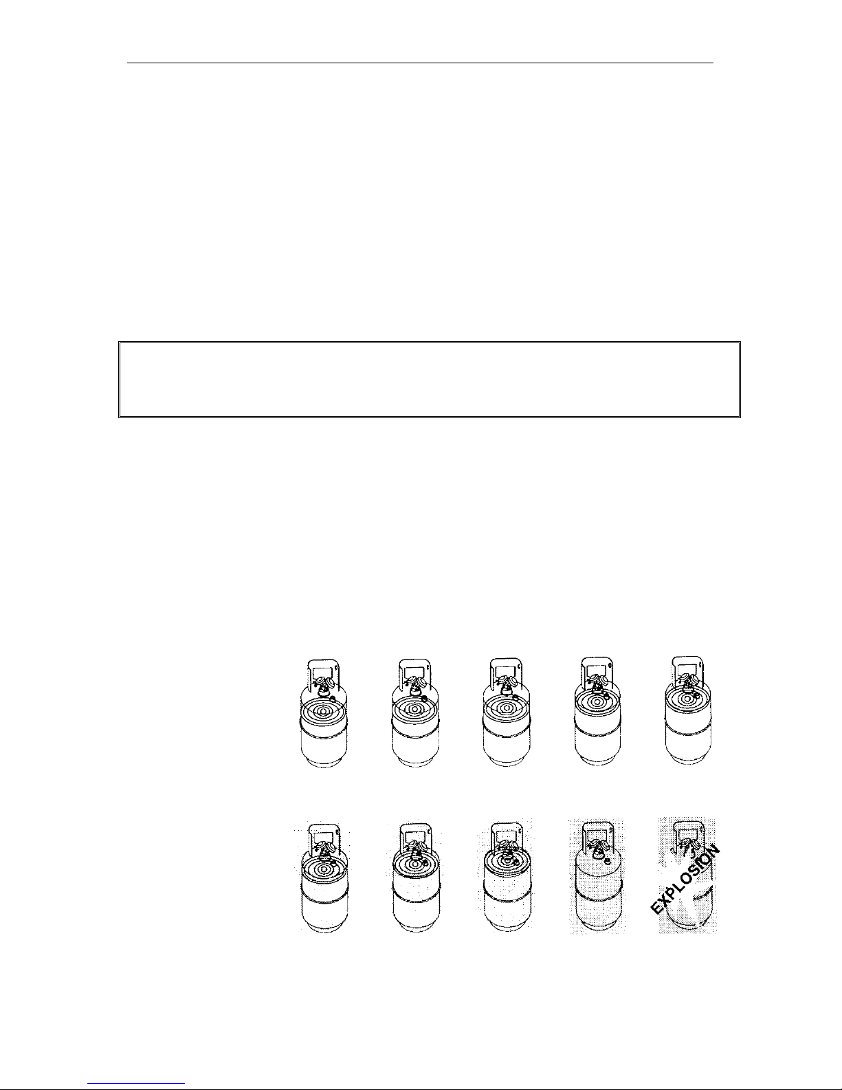
Safety codes recommend that closed tanks not be filled over 80% of volume with liquid.
The remaining 20% is called head pressure room.
NEVER TRANSPORT AN OVERFILLED CYLINDER.
Refrigerant expands when it gets warm and may cause a tank to explode if overfilled.
CYLINDER TEMP. 16 °C 21 °C 38 °C 54 °C 66 °C
STARTING WITH
CYLINDER 80%
FULL BY VOLUME
SPACE OCCUPIED
BY LIQUID
STARTING WITH
CYLINDER 90%
FULL BY VOLUME
SPACE OCCUPIED
BY LIQUID
80 % 81% 83% 90% 94%
90% 92% 96% 100%
Page 5

Advanced Test Products RG5410A-EXTREME
3
IMPORTANT
GENERAL INFORMATION
Before operating the RG5410A-EXTREME recovery unit, read the following:
1. Always isolate large amounts of refrigerant and close off valves after use so if a leak
should develop anywhere in the system the refrigerant does not escape.
2. Storage cylinders sometimes have valves that are not properly seated when
manufactured. Keeping caps on these valves will guard against refrigerant leakage.
3. Always operate the unit on a flat level surface.
4. Your RG5410A-EXTREME has one internal high-pressure shut-off switch. If the
pressure inside the system should go above 38,5 bar (550 psi), the system will
automatically shut itself off.
CAUTION
The 38,5 bar (550 psi) switch does not prevent tank overfill. If your system shuts
off on high pressure and is connected to your tank, you may have overfilled your
tank and created a very dangerous situation! Take immediate measures to relieve
any high pressure and/or tank overfill.
5. WARNING! Never overfill storage tanks. Overfilling may cause tanks to explode.
6. A scale must be used to avoid overfilling the storage tank.
7. Tanks and filters should be designated for one refrigerant only. Before using a tank
previously used for another refrigerant, completely empty the tank, evacuate it,
purge the tank using dry nitrogen, and re-evacuate it.
8. Special care should be taken when recovering from a burned-out system. Use two
high acid capacity filters, in series. Alco type EK-162-F or Sporlan type C-162-F are
recommended.
9. When you have finished recovering from the system, flush your RG5410AEXTREME with a small amount of refrigerant oil and a small amount of clean
refrigerant to purge off any foreign substances left in the unit.
10. Always empty refrigerant from the unit into a storage tank; see Self Purge/Auto
Evacuate procedure. Liquid refrigerant left in the condenser may expand, causing
damage to components.
Page 6
Advanced Test Products RG5410A-EXTREME
4
OPERATING YOUR RG5410A-EXTREME
Connect your RG5410A-EXTREME to a 230 V outlet. Switch the main power switch to
the ON position. You should hear the fan running. Press the compressor start switch.
This "momentary" switch will start the compressor. It may be necessary, under certain
circumstances, to press this switch more than once to start the compressor.
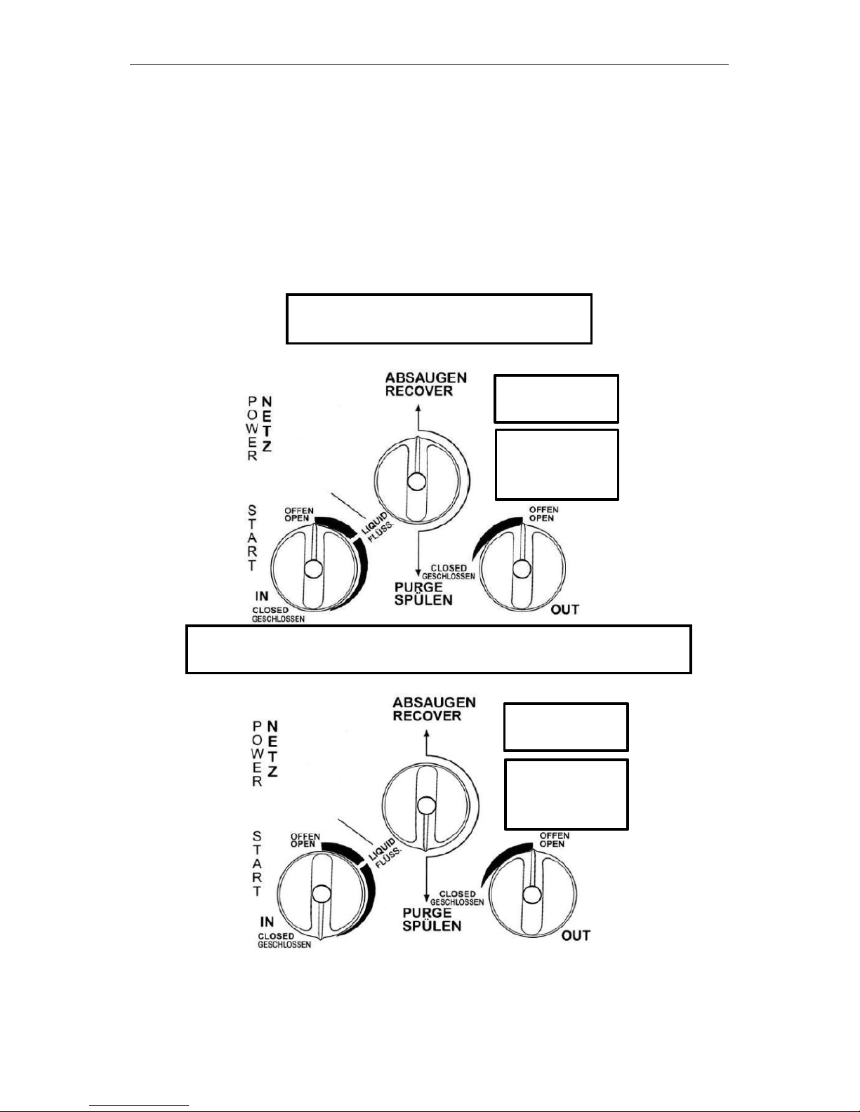
OPERATIONAL PROCEDURES
Do not turn this valve
while unit is running.
Close input valve, turn
machine off, switch to
Purge position and restart machine.
VAC
SENSOR
SELECT
ON
OFF
Do not turn this valve
while unit is running.
Close input valve, turn
machine off, switch to
Purge position and restart machine.
VAC
SENSOR
SELECT
ON
OFF
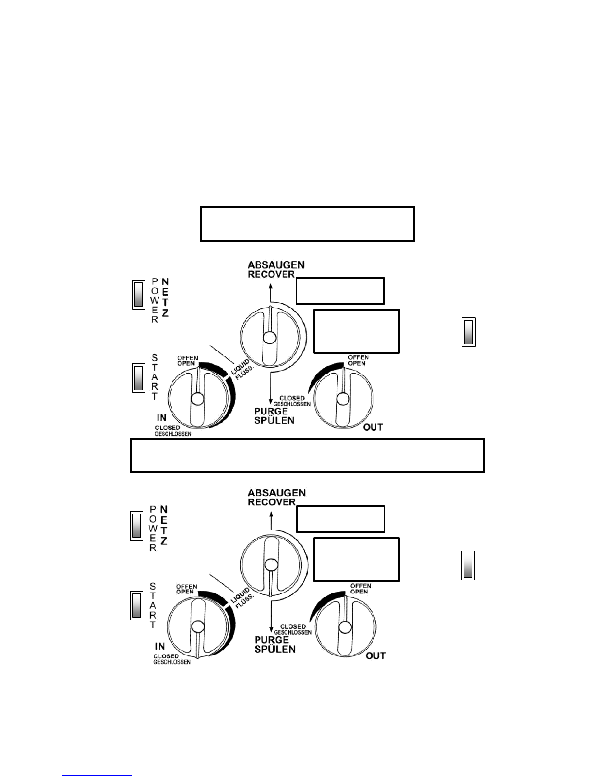
NOTE: To change from Recovery mode to Purge:
Close the Input port, turn the unit off (to prevent high pressure shutoff),
switch to Purge position and restart the unit.
NORMAL RECOVERY
SELF PURGE / AUTO EVACUATE
Page 7

Advanced Test Products RG5410A-EXTREME
5
OPERATING YOUR RG5410A-EXTREME
Procedure for Normal System Recovery
1. Inspect the RG5410A-EXTREME thoroughly to insure that it is in good operating
condition.
2. Make sure all connections are correct and tight.
3. Open the liquid port of the recovery cylinder (always open valves slowly to check
hoses and connections for leaks).
4. Make sure the Recover/Purge valve is set on Recover.
5. Open the output port of the RG5410A-EXTREME.
6. Open the liquid port on the manifold gauge set; opening the liquid port will remove
the liquid from the system first, greatly reducing the recovery time (after the liquid
has been removed, open the manifold vapor port to finish evacuating the system).
7. Connect your RG5410A-EXTREME to a 230 V outlet.
a) Switch the main power switch to the ON position. You should hear the
fan running.
b) Press the compressor start switch. This "momentary" switch will start
the compressor (it may be necessary, under certain circumstances, to
press this switch more than once to start the compressor).
8. Slowly open the input port on the RG5410A-EXTREME.
a) If the compressor starts to knock, slowly throttle back the input valve
until the knocking stops.
b) If the input valve was throttled back, it should be fully opened once the
liquid has been removed from the system (the manifold vapor port
should also be opened at this time).
9. Run until minimum EPA required vacuum is achieved.
a) Close the manifold vapor and liquid ports.
b) Close the RG5410A-EXTREME input port.
c) Shut unit off and proceed with the Self Purge procedure on the next
page.
10. Always purge the RG5410A-EXTREME after each use. Failure to purge the
remaining refrigerant from the RG5410A-EXTREME could result in the acidic
degradation of internal components, ultimately causing premature failure of the unit.
CAUTION
When pumping liquid, do not allow the RG5410A-EXTREME to operate with the
input valve too far open, causing the compressor to knock. Doing so may stall the
compressor.
Page 8

Advanced Test Products RG5410A-EXTREME
6
OPERATING YOUR RG5410A-EXTREME
Procedure for Purging Remaining Refrigerant From the RG5410A-EXTREME
1. Close the ports of the system being serviced that are connected to the input
port of the RG5410A-EXTREME.
2. Close the input port on the RG5410A-EXTREME.
3. Turn off RG5410A-EXTREME.
4. Turn the Recover/Purge valve to the purge position.
5. Restart the RG5410A-EXTREME.
6. Run until desired vacuum is achieved.
7. Close the ports on the recovery tank and the RG5410A-EXTREME.
8. Turn the RG5410A-EXTREME off.
9. Return the Recover/Purge valve to the recover position.
10. Disconnect and store all hoses.
11. Replace the in-line filter on your RG5410A-EXTREME after every time excessive
contaminant is encountered.
The use of the Low Pressure Switch
The RG5410A-EXTREME is equipped with a low pressure switch which is selectable
ON/OFF (VAC SENSOR SELECT). When the low pressure switch is switched ON the
unit will automatically switch off at 0,45 bar absolute. When the Low pressure Switch is
switched OFF the unit will continue to pump down the system even when the vacuum
stage has been reached.
VAC
SENSOR
SELECT
ON
OFF
Page 9
Advanced Test Products RG5410A-EXTREME
7
RG5410A-EXTREME REFRIGERANT RECOVERY
ADDITIONAL INFORMATION
To achieve the deepest final vacuum, use the tank cooling method to lower the head
pressure on the recovery tank. Repeat as necessary to achieve the desired vacuum
level.
NOTE: If there is no liquid in the recovery tank, then the cooling method will not work. In
this case, use an empty tank that has been fully evacuated to achieve the final vacuum
level required.
To maximize recovery rates use the shortest possible length of 3/8” or larger hose. A
hose no longer than 3’0” is recommend. Always remove all unnecessary hose core
depressors and Schrader valves from port connections (using the proper valve core
tool) for maximum throughput. Deformed rubber seals and core depressors in hoses
and faulty or unnecessary Schrader valves can restrict flow by up to 90%.
If the tank pressure exceeds 31,5 bar, use the tank cooling procedure to reduce the
tank pressure. When recovering large amounts of liquid, use the “PUSH/PULL” method
of recovery (see diagram below).
CAUTION: When using the “PUSH/PULL” method, you must use a scale to prevent
overfilling the storage tank. Once the “PUSH/PULL” siphon is started, it can continue
and overfill the storage tank even if the tank is equipped with a float level sensor. The
siphon can continue even when the machine is turned off. You must manually close the
valves on the tank and the unit to prevent overfilling the recovery tank.
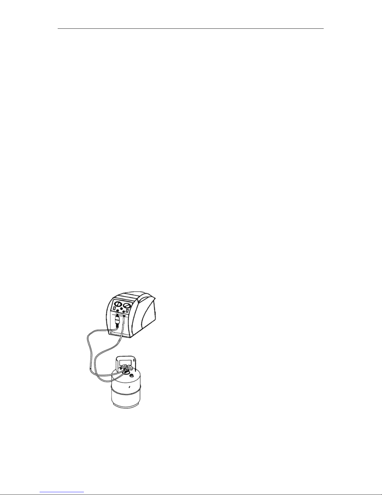
SET-UP DIAGRAM FOR TANK PRE OR SUB COOLING
PROCEDURE
INPUT
OUTPUT
VAPOR
LIQUID
To start you must have a minimum of
2,5 kg of liquid refrigerant in the tank.
Throttle the output valve so that the
output pressure is 7 bar (100 psi)
greater than the input pressure, but
never more than 31,5 bar (450 psi).
Run until the tank is cold.
Page 10
Advanced Test Products RG5410A-EXTREME
8
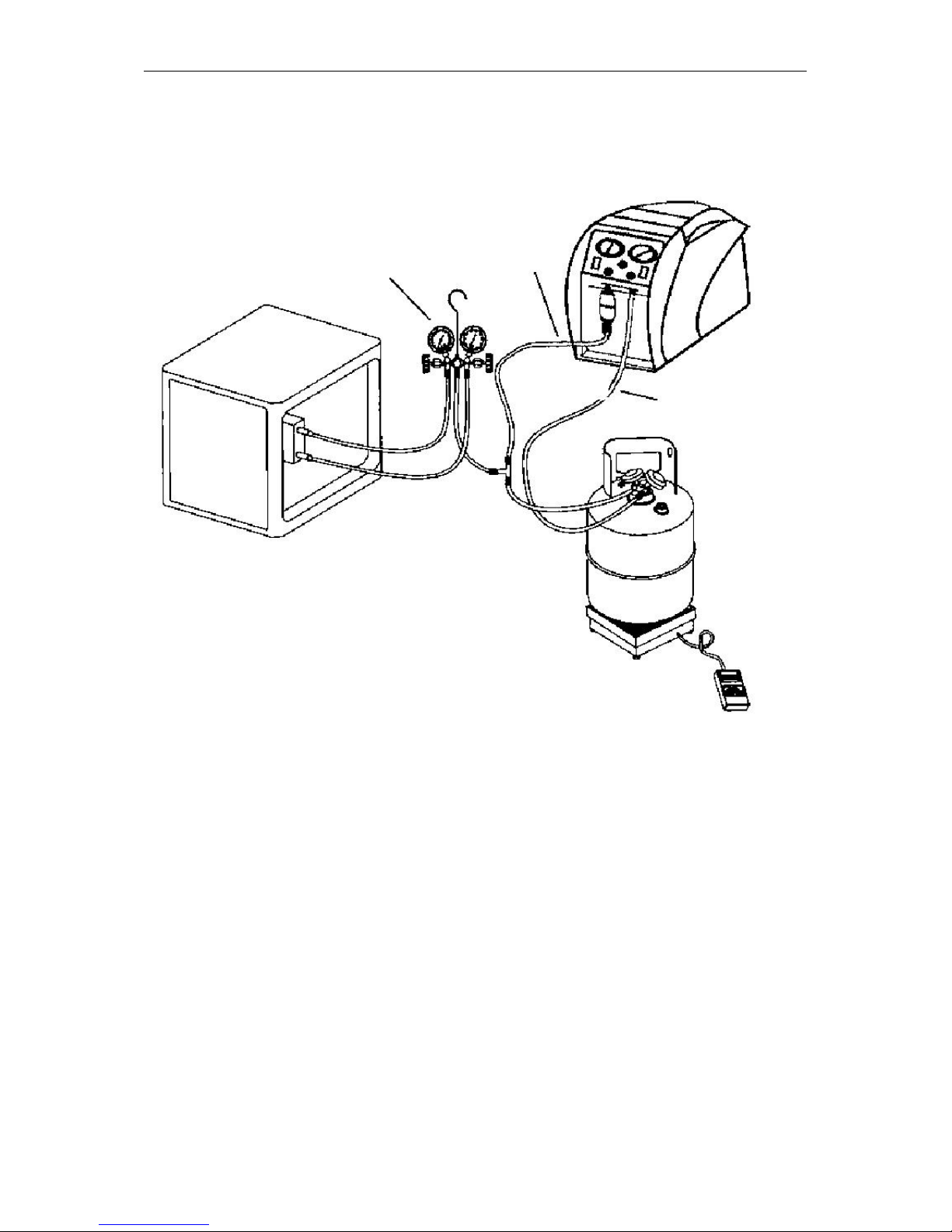
SET-UP DIAGRAM FOR REFRIGERANT RECOVERY
This method is the fastest method for recovering vapor refrigerant.
MANIFOLD GAUGE SET
(OPTIONAL) MOISTURE
SIGHT GLASS
INPUT
OUTPUT
LIQUID
A scale must be used
to avoid overfilling the
storage tank.
SYSTEM
BEING
SERVICED
VAPOR
LIQUID
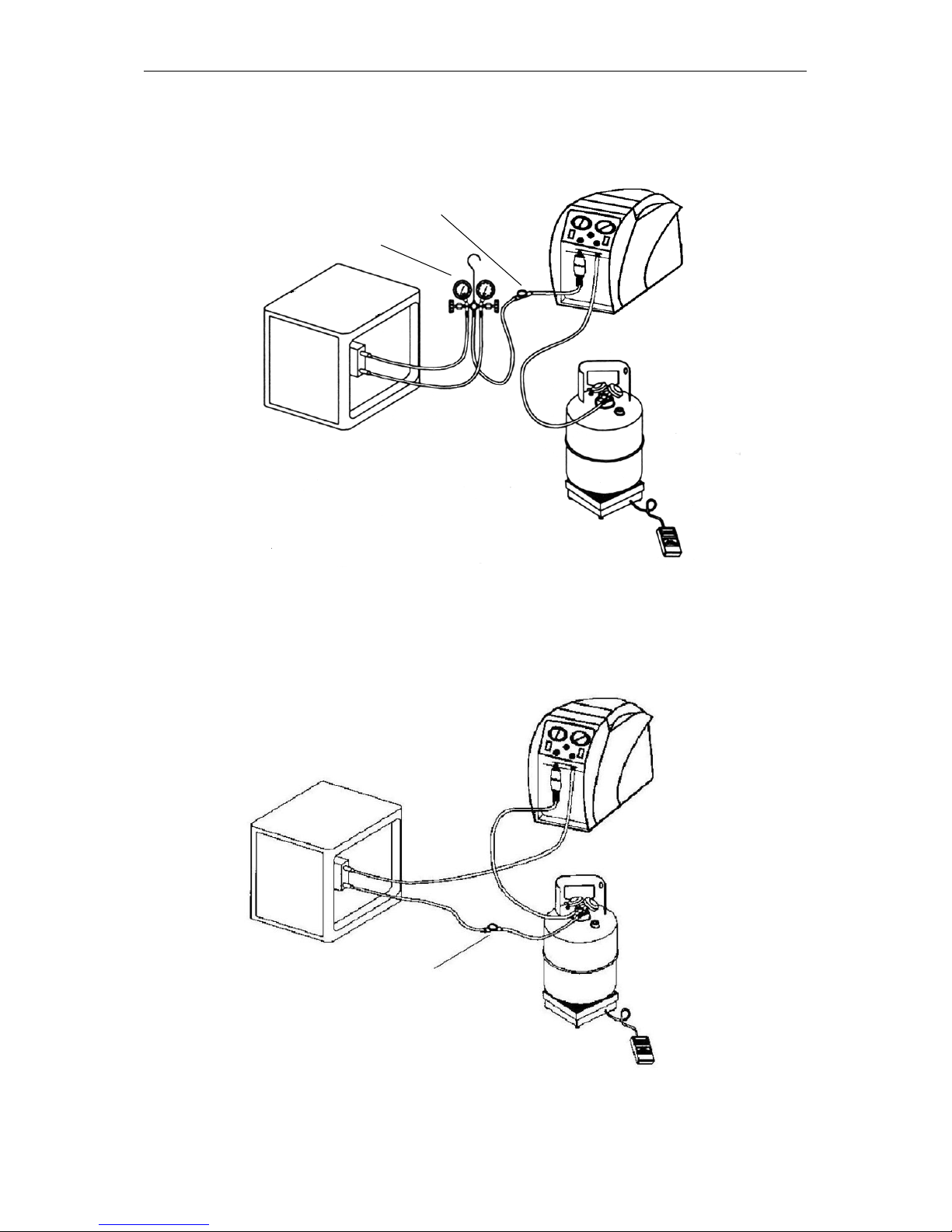
SET-UP DIAGRAM FOR “PUSH/PULL” METHOD
Push pull only works with large systems where the liquid is readily accessible. Do not
use this method on systems that contain less than 15 pounds as it may not work.
SYSTEM
BEING
SERVICED
LIQUID
VAPOR
VAPOR
LIQUID
OUTPUT
OPTIONAL MOISTURE
INDICATING SIGHT GLASS
INPUT
The sight glass is used to provide a method of
determining the moisture content and quality of a
system’s refrigerant.
A scale must be
used to avoid
overfilling the
storage tank.
Page 11
Advanced Test Products RG5410A-EXTREME
9
OPTIONAL RECOVERY / TANK PRE OR SUB
COOLING FOR FIXED HOSE SET UP
SYSTEM
BEING
SERVICED
LIQUID
VAPOR
VAPOR
LIQUID
MANIFOLD GAUGE SET
INPUT
OUTPUT
A scale must be used
to avoid overfilling the
storage tank.
Normal recovery:
Tank Vapor valve is closed.
Tank pre or sub cooling:
Tank Vapor valve is open and both Manifold Gauge Set valves are closed. Follow
above procedure.
Page 12

Advanced Test Products RG5410A-EXTREME
10
RG5410A-EXTREME RECOVERY
Purging the non-condensable gasses from identified refrigerant in a tank
1. Allow the tank to sit undisturbed for 24 hours. (This allows the air to rise to the top).
2. Connect a manifold to the tank and read the amount of pressure in the tank by
looking at the output pressure gauge.
3. Determine the ambient temperature in the room.
4. Refer to a Refrigerant pressure/temperature chart. Find the temperature on the chart
and look across to the corresponding pressure for the type of refrigerant in the tank.
Determine how that relates to the reading on the gauge.
5. If the pressure reading is higher than the pressure shown on the chart, very slowly
(so as not to cause turbulence inside the tank) crack open the vapor port valve.
Watch the pressure on the gauge decrease. To prevent venting, add 0,3 - 0,35 bar
(4 - 5 psi) to the pressure shown on the chart. When the gauge corresponds to that
pressure, close the vapor port valve.
6. Allow the tank to sit for 10 minutes and check the pressure again.
7. Repeat the process again if necessary.
Page 13
Advanced Test Products RG5410A-EXTREME
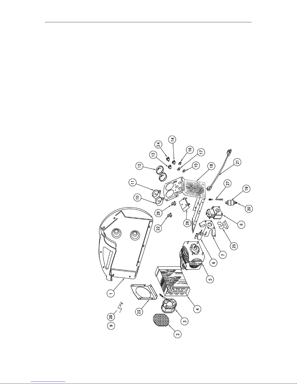
11
PARTS LIST RG5410A-EXTREME
Pos. Description Part No.
1 Plastic case 111-200119-TAB
2 Fan grill 100505
3 Axial fan EL1818
4 Condenser CD1201
5 Motor 105-200446-001
6 Coupler 534483
7 Bell housing CP1001
8 Compressor 535398ASM
9 Fuse – 5x20mm 140-200347-001
10 Input gauge 534487
11 Output gauge 534488
12 Gauge lens GA1000
13 ON/OFF switch EL1310
14 Start switch EL1309
15 Blue knob 100123
16 Red knob 100124
17 Black knob 100122
18 Front panel 110-201120-001
19 Filter 100343
20 Flare cap NB6501
21 Power cord 135-200341-001
22 High Pressure switch 100339
23 Rear panel 536762
24 Select Switch 105-200396-001
25 Compressor Bracket 100207
26 Manifold 105-200808-001
27 Hose 4“ 100345
28 Fuse holder 100419
29 VAC Sensor 113726
- Check Valve 116418
- Run Capacitor 536755
Page 14
Advanced Test Products RG5410A-EXTREME
12
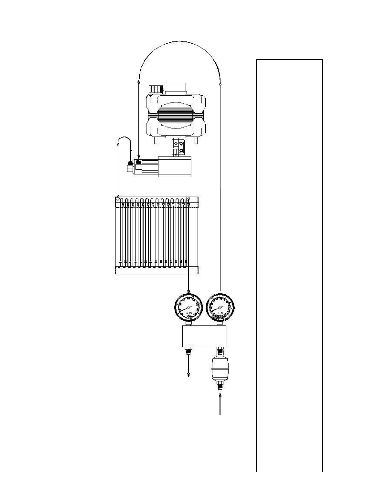
REFRIGERANT FLOW DIAGRAM
NOTE: A filter must always be used. Failure to use a filter will invalidate your warranty.
The use of a filter will greatly reduce the risk of damage to your RG5410A-EXTREME by preventing foreign material
from entering the unit.
Special consideration for filtration must be given when you know you are servicing a machine that has "Burned Out".
We recommend the use of two size 162 filter driers, in line, to be used for that job and that job only.
INPUT
CONDENSER
COMPRESSOR
MOTOR
Page 15
Advanced Test Products RG5410A-EXTREME
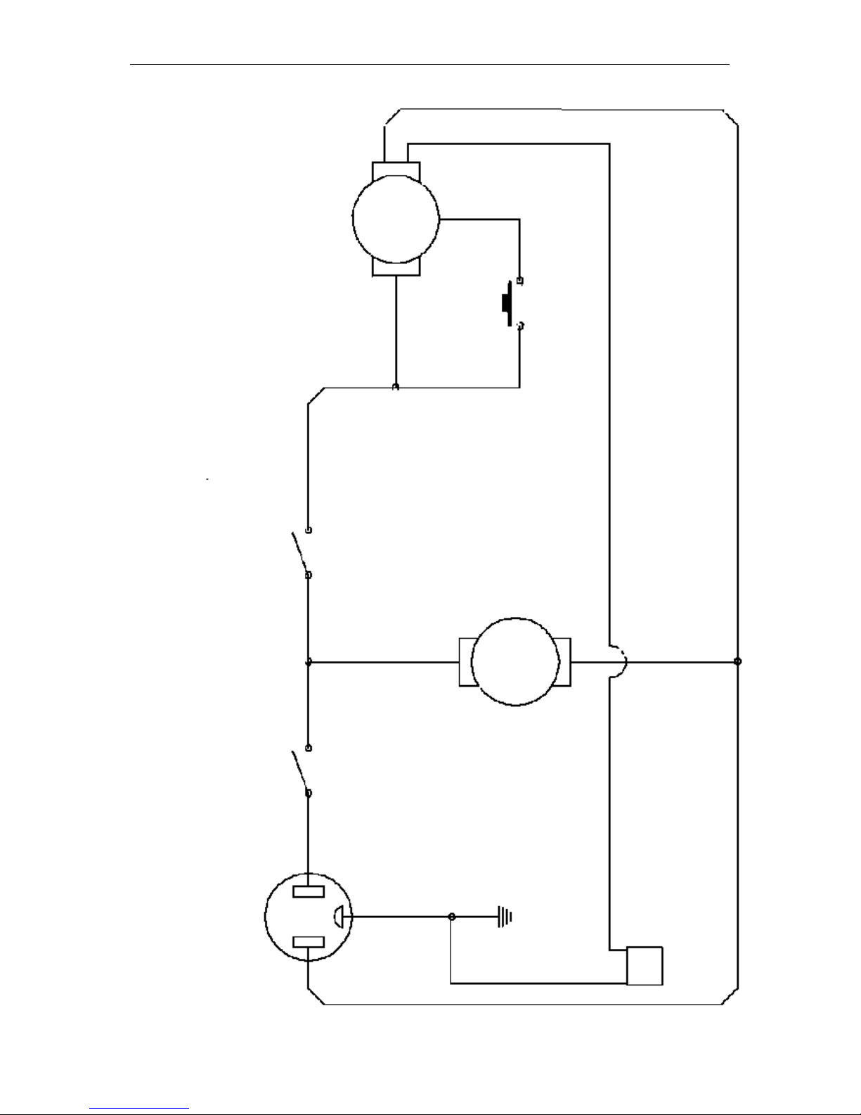
13
Plug AC Male
Power switch
High pressure switch
Fan motor
3 pin connector for
up-grade
1/2 HP motor
wht
wht
brn
red
3
2
1
6
RG5410A-EXTREME WIRING
DIAGRAM
Page 16
Advanced Test Products RG5410A-EXTREME
14
SAFETY PRESSURE SWITCH (WITH
MANUAL RESET FUNCTION)
The RG5410A-EXTREME is equipped with an internal Safety Pressure Switch. If the
pressure inside the system exceeds 38,5 bar, the system is switched off automatically.
If the Safety Pressure Switch is activated automatically whilst filling a bottle, it could be
caused by the bottle becoming overfilled.
This is a very dangerous situation! You should take steps immediately to reduce the
overpressure and/or to eliminate the overfilling of the bottle.
If the Safety Pressure Switch switches the unit off...
The following precautions should be taken if the Safety Pressure Switch is activated:
a) Suspected overfilling of the recovery bottle
Connect the recovery bottle to another bottle with spare capacity so that the pressure is
reduced to a safe level. This action should also reduce the pressure in the output line
from the RG5410A-EXTREME. Proceed as normal after resetting the Safety Pressure
Switch (see below).
b) Cause of activation of Safety Pressure Switch unknown
1) Check that the recovery bottle is not overfilled.
2) Close the system valves, recovery bottle valves and RG5410A-EXTREME valves.
3) Disconnect RG5410A-EXTREME from flexible pipes.
4) Disconnect RG5410A-EXTREME from the power supply.
5) Open the input and output valves very slowly.
6) Investigate the reason for the failure.
Once activated the Safety Pressure Switch has to be reset manually as follows:
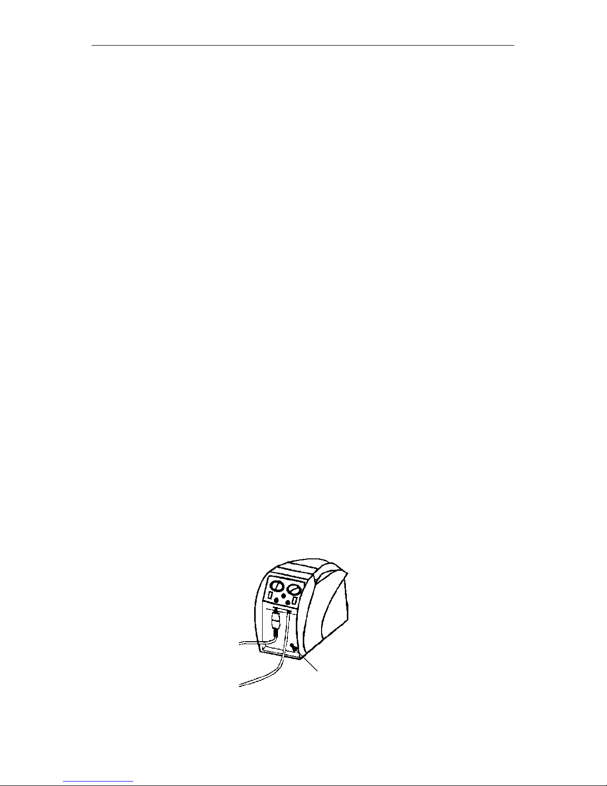
I) Remove the black protection cover to reveal the reset button (see picture below).
II) Reset by pushing the reset button with a tool such as a screwdriver.
III) Replace the cover.
Remove this part in order to
Reset the pressure switch.
Page 17

Advanced Test Products RG5410A-EXTREME
15
CARE AND MAINTENANCE OF YOUR
RG5410A-EXTREME
A filter must always be used and should be replaced frequently. Failure to use a filter
will invalidate your warranty. The use of a filter will greatly reduce the risk of damage to
your RG5410A-EXTREME by preventing foreign material from entering the unit.
Special consideration for filtration must be given when you know the machine you are
servicing has "burned out". We recommend the use of two size 162 filter driers, in line,
to be used for that job and that job only. We also recommend that a clean filter be used
for every service job. Each filter should be labeled and used exclusively for one type of
refrigerant only.
Do not use this unit in the vicinity of spilled or open containers of gasoline or other
combustible liquids
Avoid the use of extension cords. If you must use an extension cord it should be a
minimum of 14 AWG and not longer than 25 ft. Not using an extension cord will greatly
reduce the risk of fire.
Always purge the unit of any refrigerant left after completing a service job. Refrigerant
left in the machine can expand and may cause damage to components.
If the unit is to be stored or not used for any length of time, we recommend that it be
completely evacuated of any residual refrigerant and purged with dry nitrogen.
Whenever you perform any type of maintenance work on your RG5410A-EXTREME,
insure that it is disconnected from the power supply before you begin.
Page 18

Advanced Test Products RG5410A-EXTREME
16
TECHNICAL SPECIFICATIONS
Type RG5410A-EXTREME
Application Refrigerant recovery Gas or Vapor
Suitable refrigerants R12, R22, R134A, R401A, R401B, R401C, R402A, R402B,
R404A, R406A, R407A, R407B, R407C, R407D, R408A,
R409A, R410A, R411A, R411B, R412A, R500, R502, R507,
R509
Power Source 230V / 50 Hz
Power 380 W
Dimensions 330 x 229 x 483 mm
Weight 14,5 kg
RPM´s 1437 U/min
Max. working pressure 550 p.s.i. (38,5 bar)
Fuse 5x20mm, slow blow, 8A 250V
Safety Device Safety pressure switch type P100 DA
with manual reset (550 p.s.i. / 38,5 bar)
ATTENTION
The RG5410A-EXTREME should not be used with inflammable gases
nor with gases containing ammonia.
Page 19

Advanced Test Products RG5410A-EXTREME
17
HELPFUL HINTS FOR REFRIGERANT
RECOVERY
Refrigerant recovery has come a long way in a few short years.
On the surface it’s simply the process of taking refrigerant out of a system and putting it
into a tank. However, this simple process can quickly become problematic if a few items
are overlooked. The following are some tips and pointers we’ve accumulated over the
last few years that can save you time and make the process go smoother.
First you need to identify the refrigerant type and quantity in the system you are
servicing.
If you determine it’s a burnout, you need a special tank (a tank that’s identified as
containing burnout or other unidentified gases), and you need to use extra filtration prior
to recovery.
If, on the other hand, you know the gas in the system is relatively clean or new, then a
new tank should be used. If you’re planning on putting the refrigerant back into the
same system after you have finished the service or if the refrigerant is going to be
reclaimed, then use a tank that has the same refrigerant in it. A word of caution about
the Environmental Protection Agency (EPA): If you use a variety of refrigerant gasses in
your service work - as evidenced by your refrigerant purchases - and you only own one
tank, you are asking for trouble. You would be well advised to own at least one tank for
every refrigerant type serviced, plus an extra for burnouts and other unknowns.
Planning Ahead
Knowing the quantity of refrigerant is important for planning storage requirements, as
well as planning for the actual recovery. For instance, any system with more than 5lbs.
of refrigerant is likely to have areas where the liquid can get trapped.
The key to a quick recovery procedure is to get the liquid out first, and then get the
remaining vapor out. However most systems are not “recovery friendly.” That is they
don’t have access ports at their lowest points. If some units you’re servicing are on
maintenance contracts, you would save significant time by installing access ports at all
of the lowest points in the system, where liquid is likely to accumulate. Since most
systems don’t have these ports you need to be prepared to boil of the trapped liquid
with a heat gun, when ever it’s found. An indicator of trapped liquid in a system is frost
or condensation forming on the plumbing or components where the liquid is trapped.
The trapped liquid may be in an area that is not visible. In all cases trapped liquid in a
system during recovery causes the recovery process to slow down, regardless of the
size or type of machine
If you are unable to locate the trapped liquid (but you know it’s there, because the
recovery job is taking “forever”), turn on the system compressor (if it’s operable) for a
few seconds. This will get the refrigerant moving to another part of the system and in.
Page 20

Advanced Test Products RG5410A-EXTREME
18
HOSES AND VALVES
Hoses and Schrader valves have a large impact on recovery speed. In general, the
larger the hose, the less friction on the flow of refrigerant and the quicker the recovery
time. Many contractors are now using 3/8” lines for the input to the recovery machine,
even if those lines originate out of 1/4” fittings.
Schrader valves must be removed from the connection prior to an expedient
recovery. Most wholesalers sell a tool for removing these cores, while keeping the
connection sealed. The core depressor, in the end of the hose, should also be removed.
These two items can turn a 20 minute job into one that goes on for hours. So, be sure to
remove Schrader valves and core depressors before every recovery job.
Another hose consideration is the little rubber grommet at the end of the hose that
makes a seal with the flare fitting. We’ve seen these seals so worm and deformed that
when the hose is connected to the flare fitting the grommet virtually seals off the the
connection. This is probably never noticed in charging, because the pressure opens the
grommet, but during recovery (or with suction) the deformed grommet severely restricts
the flow of refrigerant.
Refrigerant Recycling
Current regulations state that used refrigerant shall not be sold, or used in a different
owner’s equipment, unless the refrigerant has been laboratory analyzed and found to
meet the requirements of ARI 700 (latest edition). As a result, recycling and verifying
ARI 700 conformance isn’t economically justified in most cases. It’s still a great idea to
do as much cleaning of refrigerant going back into the same system (or owners
system) as possible. We recommend using the largest, high-acid capacity filter that are
economically feasIble. Put these filters on the suction or inlet side of the recovery unit.
Change filters often.
The recovery of large amounts of liquid refrigerant can sometimes carry with it large
quantities of oil, if the system being serviced doesn’t have an adequate oil separator
installed. If this recovered refrigerant isn’t going to be liquid charged back into the same
system, you might want to separate the refrigerant from the oil in order to
measure the oil (to know how much oil to charge back into the system). However
refrigerant sent back for reclaim does not need to have the oil removed. One of the
simplest and most cost effective ways to achieve this is to use a 30 or 50 lb. tank in line
with your recovery machine. Connect the the system to the liquid port of the tank then
from the vapor port of the tank connect to the input of your recovery machine a second
tank, for storing refrigerant, should then be connected to the output of the recovery
machine. If you encounter large amounts of liquid you will need to put a band heater
around the first tank.
When the recovery job is complete the oil can be removed, from the first tank, by
applying a small amount of pressure, using nitrogen, to one of the ports and
expressing the oil from the other. If you are going to remove the oil from the vapor port
you will need to turn the tank upside down. Always wear safety glasses when
performing this operation as the oil may be acidic and could cause severe burning.
Page 21

Advanced Test Products RG5410A-EXTREME
19
KEEPING THE DIRT OUT
During the recovery process your recovery machine can be exposed to debris that can,
potentially, damage it. Including brazing spatter and copper and brass slithers. Further
contamination can be introduced from the refrigerant storage tanks. To
prolong the life of your recovery machine always use an in-line filter.
Whenever you are charging a system from a recovery cylinder it is a good idea to use
an in-line filter to protect the system from contamination. Again, change your
in-line filters often.
Getting the Liquid Out (See “Push/Pull-Method”)
Push-pull is a method of removing bulk liquid from a system using the pressure
differential created by the recovery machine. Push-pull will generally not work on
smaller systems because there is no bulk liquid reservoir to create a siphon from.
Push-pull is mostly used on systems with a receiver tank or those with greater than 20
lbs. of refrigerant, or when transferring from one tank to another. The rate of liquid
transfer is very much dependent on hose size, with larger hoses providing much
better throughput.
Another trick is to chill the tank, if it’s partially filled, prior or during recovery. This
operation will lower the pressure in the storage tank and therefore speed up recovery.
There must be a minimum of 5 lbs of liquid refrigerant in the tank you wish to chill. This
operation can be performed prior to or during the recovery. See the two set up diagrams
and procedures on page 8 of this manual.
There is nothing magic here, you are simply using your recovery machine to make a
refrigerator where the tank is the evaporator. By throttling the output valve, you’re
effectively creating a capillary tube or an expansion device, but you need to adjust the
backpressure to suit the conditions and the refrigerant. Five to ten minutes of chilling
can produce some very dramatic tank cooling, depending on the conditions. If there are
any non-condensable in the tank this process will not work. Also the greater the quantity
of refrigerant in the tank the longer the process will take.
Page 22
Advanced Test Products RG5410A-EXTREME
20
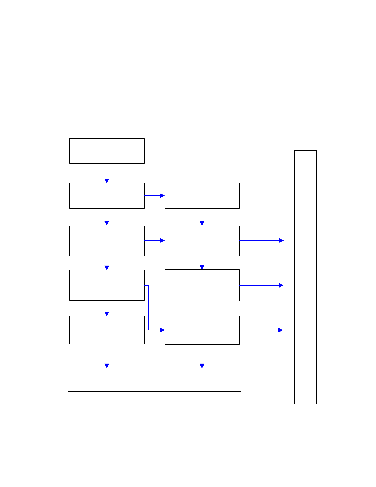
TROUBLESHOOTING YOUR
RG5410A-EXTREME
The safe way is the only way
Read and understand all safety information contained in this manual
before servicing the unit.
Connect unit to 220 V outlet
Fan is running when power
switch is in "ON" position?
Compressor starts when
start switch is pressed
Unit pumps into high
pressure shut off?
Power supply ok?
TROUBLESHOOTING ENDS
Are your hoses tight? Do
you have leaks?
Unit pulls into a vacuum?
Is unit in high pressure shut
off?
Are valves open?
Reset button pushed?
yes
no
yes
yes
no
ye
no
yes
yesnoyes
no
j
yes
yes
C
O
N
T
A
C
T
P
R
O
M
A
X
S
E
R
V
I
C
E
Page 23
BENUTZERHANDBUCH
RG5410A-EXTREME
Page 24

Advanced Test Products RG5410A-EXTREME
2
INHALTSVERZEICHNIS
I) Sicherheitshinweise
A) Sicherheit ist oberstes Gebot 1
B) Kältemittelabsaugungs- und Serviceverfahren 2
II) Wichtige allgemeine Informationen 3
III) Betriebsverfahren
A) Betrieb des RG5410A-EXTREME 4-6
Gebrauch des Niederdruckschalters 6
B) Aufbau / Anschluss 7-9
C) Evakuierung der nicht kondensierbaren Gase 10
IV) Pläne und Listen
A) Teileliste 11
B) Kältemittel-Flussdiagramm 12
C) Schaltplan 13
V) Sicherheitsdruckbegrenzer (SDBK) 14
VI) Pflege und Wartung 15
VII) Technische Daten 16
VIII) Nützliche Hinweise zur Kältemittelabsaugung 17-20
IX) Störungssuche 21
X) Garantie 22
Irrtum sowie Änderungen der technischen Daten und Materialien ohne vorherige Ankündigung
vorbehalten.
Dieses Handbuch darf ohne ausdrückliche schriftliche Genehmigung von ADVANCED TEST
PRODUCTS auf keinerlei Weise und in keiner Form vervielfältigt werde.
Page 25

Advanced Test Products RG5410A-EXTREME
1
SICHERHEIT IST OBERSTES GEBOT
HINWEIS: Nur sachkundige, im Umgang mit Kältemitteln geschulte Personen
dürfen dieses Gerät bedienen.
1. Bei Arbeiten an Kälteanlagen sind stets Schutzbrille und Handschuhe zu tragen.
2. Die Räume, in denen das Gerät betrieben wird, müssen gut belüftet sein, vor allem
bei Verdacht auf ein Leck. Kältemitteldämpfe sind gesundheitsschädlich und
möglicherweise tödlich.
3. Zuerst denken, dann handeln! Vertrautheit mit einem Gerät verführt zu Unaufmerksamkeit, und Unaufmerksamkeit kann zu Gesundheitsschäden oder gar zum
Tode führen.
4. Lesen Sie die Sicherheitsdatenblätter sämtlicher Verbindungen durch, mit denen
Sie in Kontakt kommen können. Lesen Sie die Sicherheitsdatenblätter des Kältemittels und Kältemaschinenöls. Sicherheitsdatenblätter können Sie von Ihrem
Kältemittellieferanten anfordern.
5. Verwenden Sie niemals Sauerstoff zur Prüfung auf Lecks. Jede Art von Öl, die in
Kontakt mit unter Druck stehendem Sauerstoff gelangt, ergibt eine explosive
Mischung.
6. Kälteanlagen werden im allgemeinen elektrisch betrieben und gesteuert. Trennen
Sie die Anlage vor der Ausführung von Wartungsarbeiten vom Netz.
7. Kältemittelbehälter sind stets an einem kühlen, trockenen Ort aufzubewahren.
8. Service- und Flaschenventile sind stets langsam zu öffnen. Besteht eine Gefahr,
kann der Gasfluß schnell unterbunden werden. Steht fest, daß keine Gefahr
besteht, können die Ventile vollständig geöffnet werden.
9. Unterschiedliche Kältemittel dürfen weder in Anlagen noch in Flaschen noch sons
gemischt werden. Für jedes Kältemittel ist eine eigene Flasche, ein eigener Filter
usw. erforderlich.
10. Tritt Feuchtigkeit in eine Kälteanlage ein, kann dies beträchtliche Schäden verursachen. Sämtliche Teile der Kälteanlage sind stets trocken und sauber zu halten.
11. Um das Risiko von Bränden zu verringern sollten Sie keine Verlängerungskabel
verwenden, da sich diese überhitzen können. Sollte es jedoch unumgänglich sein,
ein Verlängerungskabel zu verwenden, so sollte dieses ein Minimum von 14 AWG
besitzen (Querschnittsfläche Kabel: 2 mm²) und nicht länger als 7,5m sein. Dieses
Gerät darf in Räumen eingesetzt werden, bei denen durch mechanische
Lüftungsmaßnahmen mindestens vier Luftwechsel in der Stunde gewährleistet sind,
oder das Gerät muss sich mindestens 45 cm oberhalb des Bodens befinden.
Dieses Gerät darf nicht in der Nähe von verschüttetem Benzin oder offenen
Behältern mit Benzin oder anderen brennbaren Flüssigkeiten eingesetzt werden.
Page 26
Advanced Test Products RG5410A-EXTREME
2
RG5410A-EXTREME
KÄLTEMITTELABSAUGUNGS- UND
SERVICEVERFAHREN
Sicherheit steht an erster Stelle. Lesen Sie alle Sicherheitsinformationen zur sicheren
Handhabung von Kältemitteln sowie die Sicherheitsblätter Ihres Kältemittellieferanten
durch. Der Betrieb des Gerätes in explosionsgefährdeten Umgebungen ist unzulässig.
Tragen Sie stets Schutzbrille und Schutzhandschuhe. Das Gerät darf nur in gut
belüfteten Räumen betrieben werden. Nur sachkundige, im Umgang mit Kältemitteln
geschulte Personen dürfen dieses Gerät bedienen.
*** VORSICHT: KÄLTEMITTELFLASCHEN ***
Nur zugelassene und geprüfte, den relevanten Normen entsprechende Flaschen mit
einem zulässigen Betriebsdruck von mindestens 41 bar dürfen verwendet werden.
HINWEIS: Kältemittel- und Recyclingflaschen sind für unterschiedliche Drücke
ausgelegt. Der Arbeitsdruck der Flaschen darf nicht überschritten werden.
Die Sicherheitsvorschriften empfehlen, geschlossene Flaschen zu nicht mehr als 80%
ihres Volumens mit Flüssigkeit zu füllen. Die restlichen 20% werden als Kopfraum
bezeichnet.
DER TRANSPORT ÜBERFÜLLTER KÄLTEMITTELFLASCHEN IST UNZULÄSSIG.
Kältemittel dehnen sich bei Erwärmung aus – überfüllte Flaschen können bersten.
FLASCHENTEMP. 16 °C 21 °C 38 °C 54 °C 66 °C
AUSGANGSFÜLLUNG
80 VOL%
FLÜSSIGKEITSFÜLLGRAD
AUSGANGSFÜLLUNG
90 VOL%
FLÜSSIGKEITSFÜLLGRAD
80 % 81% 83% 90% 94%
90% 92% 96% 100%
Page 27

Advanced Test Products RG5410A-EXTREME
3
WICHTIGE ALLGEMEINE
INFORMATIONEN
Vor Betrieb des Absaugerätes RG5410A-EXTREME sind unbedingt folgende
Informationen durchzulesen:
1. Große Kältemittelmengen sollten isoliert werden, und nach Gebrauch sollten die
Ventile geschlossen werden, so daß im Falle eines Lecks in der Anlage kein
Kältemittel austreten kann.
2. Neue Kältemittelflaschen werden in einigen Fällen mit nicht richtig sitzenden Ventilen
geliefert. Kappen auf solchen Ventilen können das Austreten von Kältemittel
verhindern.
3. Das Gerät ist stets auf einer ebenen Fläche zu betreiben.
4. Das RG5410A-EXTREME ist mit einem internen Sicherheitsdruckbegrenzer
ausgerüstet. Überschreitet der Druck im System 38,5 bar, wird das System
automatisch abgeschaltet.
ACHTUNG
Auch ein Sicherheitsdruckbegrenzer (SDBK) kann die Überfüllung der Flasche
nicht verhindern. Wird das System bei hohen Drücken abgeschaltet und ist mit
einer Flasche verbunden, wurde die Flasche möglicherweise überfüllt. Dies ist ein
äußerst gefährlicher Zustand ! Maßnahmen zum Abbau des Überdrucks und/oder
zur Beseitigung der Überfüllung sind sofort zu treffen.
5. WARNUNG! Kältemittelflaschen dürfen niemals überfüllt werden. Überfüllung kann
zum Bersten der Flaschen führen.
6. Während des Absaugvorganges müssen Kältemittelflaschen gewogen werden um
ein Überfüllen der Flaschen auszuschließen.
7. Flaschen dürfen nur für jeweils ein Kältemittel verwendet werden. Bevor Sie eine
Flasche verwenden, die zuvor für ein anderes Kältemittel verwendet wurde, ist die
Flasche vollständig zu entleeren und zu evakuieren. Anschließend ist die Flasche mit
trockenem Stickstoff zu spülen und erneut zu evakuieren.
8. Bei der Absaugung einer ausgebrannten Anlage ist besondere Vorsicht geboten. In
solchen Fällen sind zwei in Serie geschaltete Filter mit hoher Säurekapazität zu
verwenden. Empfohlen werden Filter des Typs C-162-F von Sporlan. (Promax
Teil Nr. FL-1201)
9. Nach beendigter Absaugung ist das RG5410A-EXTREME mit einer geringen Menge
Kältemaschinenöl und einer geringen Menge sauberen Kältemittels zu spülen, um im
Gerät verbliebene Fremdsubstanzen zu entfernen.
10.Kältemittel ist stets aus dem Gerät in eine Flasche zu pumpen. Im Verdichter
verbleibendes Kältemittel kann sich ausdehnen und das Gerät beschädigen.
Page 28
Advanced Test Products RG5410A-EXTREME
4
BETRIEB DES RG5410A-EXTREME
Schließen Sie das RG5410A-EXTREME an eine 230 V-Steckdose an. Schalten Sie den
Netzschalter ein (ON-Position). Der Lüfter läuft. Drücken Sie zum Starten des
Kompressors den Kompressor-Starttaster. In manchen Fällen ist es eventuell
erforderlich, diesen Taster mehrmals zu drücken, um den Kompressor zu starten.
BETRIEBSARTEN
Das schwarze Ventil darf
bei laufendem Gerät
nicht betätigt werden.
Einlassventil schließen,
Gerät ausschalten.
In Purge-Position
schalten und Gerät
erneut starten.
Das schwarze Ventil darf
bei laufendem Gerät
nicht betätigt werden.
Einlassventil schließen,
Gerät ausschalten.
In Purge-Position
schalten und Gerät
erneut starten.
HINWEIS: Wechsel vom Absaug- zum Spülmodus:
Einlaßventil schließen, Gerät ausschalten (um Hochdruckabschaltung zu
vermeiden), auf Spülposition (PURGE) umschalten und Gerät erneut starten.
NORMALES ABSAUGEN
SELBSTSPÜLUNG / AUT. EVAKUIERUNG
Page 29

Advanced Test Products RG5410A-EXTREME
5
BETRIEB DES RG5410A-EXTREME
Betriebsart RECOVER: („normales Absaugen von Kältemittel“)
1. Vergewissern Sie sich, daß das RG5410A-EXTREME keine äußeren Schäden
aufweist.
2. Stellen Sie sicher, daß alle Anschlüsse und Verbindungen korrekt und fest
angeschlossen sind.
3. Stellen Sie sicher, daß das „Recover/Purge“ Ventil auf Recover eingestellt ist.
4. Öffnen Sie die Ventile des zu wartenden Systems langsam.
5. Öffnen Sie das Flüssigkeitsventil der Manometerventil.
6. Stellen Sie das Einlaßventil am RG5410A-EXTREME auf die Position „Liquid“
(flüssig.
7. Stellen Sie das Auslassventil am RG5410A-EXTREME auf die Position „OPEN“
(offen.
8. Öffnen Sie das Flüssigkeitsventil der Kältemittelflasche.
9. Schließen Sie das RG5410A-EXTREME an eine 230V Spannungsquelle an.
a)Stellen Sie den Netzschalter des RG5410A-EXTREME in die Position
„ON“, dadurch wird zunächst nur der Ventilator aktiviert.
b) Drücken Sie nun den Kompressor-Starttaster um das RG5410AEXTREME in Betrieb zu setzen.
10. Nachdem Sie sich überzeugt haben das alles ordnungsgemäß funktioniert, sollten
Sie das Einlaßventil des RG5410A-EXTREME langsam in die Stellung „OPEN“
drehen, jedoch nur soweit, dass kein lautes Schlagen (Klopfen) auftritt. Dieses
Schlagen bzw. Klopfen des Kompressors tritt nur dann auf, wenn der Verdichter
zuviel Flüssigkeit pumpt.
11. Betreiben Sie das RG5410A-EXTREME bis das erforderliche Vakuum erreicht wird.
12. Nach der Beendigung der Kältemittelabsaugung sollte auch das RG5410AEXTREME vom Kältemittel befreit werden (siehe Funktion „Selbstentsorgung
/Purge“).
ACHTUNG
Beim Absaugen von flüssigem Kältemittel sollte das Einlaßventil nicht zu weit
geöffnet werden da es sonst zu lauten Schlägen (Klopfen) des Kompressors
kommen kann. Dieses Schlagen bzw. Klopfen des Kompressors tritt nur dann auf
wenn der Verdichter zu viel Flüssigkeit pumpt, dadurch kann der Motor
abgewürgt werden.
Page 30

Advanced Test Products RG5410A-EXTREME
6
BETRIEB DES RG5410A-EXTREME
Betriebsart PURGE : („Evakuierung verbliebener Kältemittelreste im RG5410AEXTREME“)
1. Schließen Sie die Ventile des zu wartenden Systems welches am Einlaßventil des
RG5410A-EXTREME angeschlossen ist.
2. Schließen Sie das Einlaßventil am RG5410A-EXTREME (Position „CLOSED“).
3. Schalten Sie das RG5410A-EXTREME aus.
4. Stellen Sie nun das „Recover/Purge“ Ventil auf Position PURGE.
5. Starten Sie nun das RG5410A-EXTREME.
6. Betreiben Sie das RG5410A-EXTREME bis das gewünschte Vakuum erreicht ist.
7. Schließen Sie das Flüssigkeitsventil der Kältemittelflasche.
8. Schließen das Auslassventil am RG5410A-EXTREME (Position „CLOSED“).
9. Schalten Sie das RG5410A-EXTREME ab.
10. Stellen Sie nun das „Recover/Purge“ Ventil wieder auf Position RECOVER.
11. Entfernen Sie alle Zuleitungen vom RG5410A-EXTREME.
12. Wechseln Sie nach jedem Absaugen stark verschmutzter Kältemittel immer den
Einlassfilter am RG5410A-EXTREME.
Die Bedienung des
Niederdruckschalters
Das RG5410A-EXTREME ist mit einem Niederdruckschalter ausgerüstet, den man bei
Bedarf ein- bzw. ausschalten kann (ON/OFF VAC SENSOR SELECT). Bei aktiviertem
Nieder-druckschalter schaltet das Gerät bei einem Druck von 0,45 bar absolut ab. Ist
der Niederdruckschalter ausgeschaltet, saugt das Gerät auch nach Erreichen dieses
Druckniveaus kontinuierlich weiter.
VAC
SENSOR
SELECT
ON
OFF
Page 31

Advanced Test Products RG5410A-EXTREME
7
VORBEREITUNG FÜR KÄLTEMITTELABSAUGUNG
Um den maximalen Endunterdruck zu erreichen, ist mit Hilfe des Flaschenkühlungsverfahrens der Kopfdruck in der Absaugflasche zu verringern. Wiederholen Sie dieses
Verfahren, bis der gewünschte Unterdruck erreicht ist.
HINWEIS: Enthält die Absaugflasche keine Flüssigkeit, funktioniert dieses Kühlverfahren nicht. In diesem Falle kann zum Erreichen des erforderlichen Endunterdrucks
eine vollständig evakuierte leere Flasche verwendet werden.
Zur Maximierung der Absauggeschwindigkeit sollten möglichst kurze Schläuche mit
einem Durchmesser von mindestens 3/8" verwendet werden. Eine maximale Schlauchlänge von ca. 90 cm wird empfohlen. Um den maximal möglichen Durchsatz zu
erreichen, sind alle unnötigen Tuyau abaisse de baseund Schraderventile unter
Verwendung geeigneter Ventileinsatzwerkzeuge von den Anschlüssen zu entfernen.
Verformte Gummidichtungen und Kerndrücker in Schläuchen oder defekte oder
unnötige Schraderventile können den Fluß um bis zu 90% vermindern.
Wenn der Druck in der Flasche den Wert 31,5 bar überschreitet, müssen Sie die
Flasche kühlen. Benutzen Sie hierfür den Aufbau für die Vor- oder Nachkühlung der
Flasche. Wenn Sie größere Mengen an flüssigem Kältemittel absaugen benutzen Sie
die unten angeführte „DRUCK-ZUG-METHODE“.
ACHTUNG: Bei Verwendung der „DRUCK-ZUG-METHODE" ist eine Waage
erforderlich, um das Überfüllen der Flasche zu vermeiden. Wurde der "DRUCK-ZUGSIPHON" erst einmal eingeleitet, kann er sich fortsetzen und die Flasche auch dann
überfüllen, wenn diese mit einem Schwimmer-Füllstandssensor ausgerüstet ist. Die
Siphonwirkung kann sich sogar bei abgeschaltetem Gerät fortsetzen. Sie müssen die
Ventile an der Flasche und am Gerät von Hand schließen, um das Überfüllen der
Flasche zu verhindern.
AUFBAU FÜR VOR- ODER NACHKÜHLUNG DER
FLASCHE
EINLASS
AUSLASS
DAMPF
FLÜSSIGKEIT
Zu Beginn dieses Verfahrens muß die
Flasche mindestens 2,5 kg flüssiges
Kältemittel enthalten.
Drosseln Sie das Auslassventil, so daß der
Ausgangsdruck 7 bar höher als der
Einlaßdruck ist. Er darf jedoch in keinem
Falle 31,5 bar überschreiten.
Betreiben Sie das Gerät mit diesem
Aufbau, bis die Flasche kalt ist.
Page 32

Advanced Test Products RG5410A-EXTREME
8
AUFBAU FÜR KÄLTEMITTELABSAUGUNG
Dies ist das schnellste Verfahren zur Absaugung von gasförmigen Kältemitteln.
MANOMETERBATTERIE
(OPTIONAL)
FEUCHTIGKEITS-
SCHAUGLAS
EINLASS
AUSLASS
FLÜSSIGKEIT
Um Überfüllung der
Flasche zu verhindern,
muß eine Waage
verwendet werden.
ZU
WARTENDES
SYSTEM
DAMPF
FLÜSSIGKEIT
AUFBAU FÜR "DRUCK-ZUG-METHODE"
Die Druck-Zug-Methode funktioniert nur bei großen Anlagen, bei denen die Flüssigkeit
gut zugänglich ist. Diese Methode sollte bei Anlagen, die weniger als 7 kg enthalten,
nicht angewandt werden, da sie dann eventuell nicht funktioniert.
ZU
WARTENDES
SYSTEM
FLÜSSIGKEIT
DAMPF
DAMPF
FLÜSSIGKEIT
AUSLASS
OPTIONALES FEUCHTIGKEITS-
SCHAUGLAS
EINLASS
Das Schauglas gibt Aufschluß über den Feuchtigkeitsgehalt und die Qualität des in einer Anlage enthaltenen
Kältemittels.
Um die Überfüllung der
Flasche zu verhindern, muss
eine Waage
verwendet werden.
Page 33

Advanced Test Products RG5410A-EXTREME
9
OPTIONALE ABSAUGUNG / FLASCHENKÜHLUNG
FÜR FESTE SCHLAUCHSYSTEME
Aufbau für Absaugung mit betriebsbereitem Flaschenkühlschlauch
ZU
WARTENDES
SYSTEM
FLÜSSIGKEIT
DAMPF
DAMPF
FLÜSSIGKEIT
MANOMETERBATTERIE
EINLASS
AUSLASS
Um Überfüllung der
Flasche zu verhindern,
muss eine Waage
verwendet wenden.
Normale Absaugung:
Dampfventil der Flasche ist geschlossen.
Vor- oder Nachkühlung der Flasche:
Dampfventil der Flasche ist offen und beide Ventile der Manometerventil sind
geschlossen; siehe Kühlungsverfahren auf Seite 7.
Page 34

Advanced Test Products RG5410A-EXTREME
10
ABSAUGEN MIT DEM
RG5410A-EXTREME
Evakuierung der nicht kondensierbaren Gase aus einem Kältemittel in einer
Flasche
8. Lassen Sie die Flasche 24 Stunden lang ungestört stehen. Hierdurch können die
nicht kondensierbaren Gase nach oben steigen.
9. Schließen Sie die Manometerventil an die Flasche an und lesen Sie den Druck in
der Flasche ab.
10. Bestimmen Sie die Umgebungstemperatur im Raum.
11. Vergleichen Sie die Temperatur mit dem Druck des betreffenden Kältemittels.
Verwenden Sie hierfür die zugehörigen Temperatur- und Drucktabellen.
12. Wenn der abgelesene Druck höher ist als der angegebene Druck in der
Drucktabelle, öffnen Sie langsam das Ventil für Dampf. Führen Sie dies sehr
langsam aus, um Turbulenzen in der Flasche zu vermeiden. Beobachten Sie, wie
der Druck am Manometer abfällt. Addieren zu dem Druck der in den Drucktabellen
angegeben ist 0,3 bis 0,35 bar. Schließen Sie das Ventil für den Dampfanschluss an
der Flasche wenn die Manometeranzeige mit diesem Druck übereinstimmt.
13. Lassen Sie die Flasche 10 Minuten lang ruhig stehen und messen Sie den Druck
erneut.
14. Wenn nötig wiederholen Sie den oben beschriebenen Vorgang.
Page 35

Advanced Test Products RG5410A-EXTREME
11
TEILELISTE RG5410A-EXTREME
Pos. Bezeichnung Teilen.
1 Kunststoffgehäuse 111-20119-TAB
2 Lüftergitter 100505
3 Axiallüfter EL1818
4 Verflüssiger CD1201
5 Motor 105-200446-001
6 Kupplung 534483
7 Flansch CP1001
8 Kompressor 535398ASM
9 Sicherung 5x20mm 140-200347-001
10 Einlassmanometer 534487
11 Auslassmanometer 534488
12 Manometer Glas GA1000
13 Netzschalter EL1310
14 Startschalter EL1309
15 Einlassknopf 100123
16 Auslassknopf 100124
17 Modusumschalter 100122
18 Frontplatte 110-201120-001
19 Filter 100343
20 Kappe NB6501
21 Netzkabel 135-200341-001
22 Hochdruckschalter 100339
23 Rückplatte 536762
24 Niederdruckschalter 105-200396-001
25 Kompressorhalter 100207
26 Verteiler 105-200808-001
27 Schlauch 4“ 100345
28 Sicherungshalter 100419
29 Niederdrucksensor 113726
- Rückschlagventil 116418
- Führen Kondensator 536755
Page 36

Advanced Test Products RG5410A-EXTREME
12
KÄLTEMITTEL-FLUSSDIAGRAMM
HINWEIS: Ein Filter ist stets zu verwenden. Bei Nichtverwendung eines Filters besteht kein Anspruch auf Garantieleistung.
Durch Verwendung eines Filters wird das Risiko von Beschädigungen des RG5410A-EXTREME durch in das Gerät
eindringende Fremdsubstanzen beträchtlich verringert.
Die Filterung ist besonders beim Absaugen ausgebrannter Anlagen von großer Bedeutung. Wir empfehlen den Einsatz von zwei
in Serie geschalteten Filtertrocknern der Größe 162, die ausschließlich für die betreffende Anlage verwendet werden sollten.
EINLASS
VERFLÜSSIGER
KOMPRESSOR
MOTOR
Page 37

Advanced Test Products RG5410A-EXTREME
13
VERDRAHTUNGSPLAN RG5410A-EXTREME
Sicherung
Gelb
Braun
Lüfter
Braun
Braun
Braun Blau Blau Netzschalter Startknopf Hochdrucksensor Niederdrucksensor
Niederdruck-
schalter
Buchse für Netzkabel
Schwarz
Neutral
Schwarz
Neutral
Weiß
Rot
Rot
½ PS
Motor
Page 38

Advanced Test Products RG5410A-EXTREME
14
.SICHERHEITSDRUCKBEGRENZER
(SDBK)
Das RG5410A-EXTREME ist mit einem internen Sicherheitsdruckbegrenzer
ausgerüstet. Überschreitet der Druck im System 38,5 bar, wird das System automatisch
abgeschaltet.
Auch ein Sicherheitsdruckbegrenzer (SDBK) kann die Überfüllung der Flasche nicht
verhindern. Wird das System bei hohen Drücken abgeschaltet und ist mit einer Flasche
verbunden, wurde die Flasche möglicherweise überfüllt. Dies ist ein äußerst
gefährlicher Zustand ! Maßnahmen zum Abbau des Überdrucks und/oder zur
Beseitigung der Überfüllung sind sofort zu treffen.
Wenn der Sicherheitsdruckbegrenzer auslöst ...
Sollte der Sicherheitsdruckbegrenzer aufgrund von Fehlbedienung oder sonstiger
Umstände ansprechen, sind folgende Maßnahmen zu treffen:
a) Überfüllung der Flasche
Verbinden Sie die Flasche mit einer zweiten Flasche, welche noch eine ausreichende
Füllmenge aufnehmen kann, so dass der Druck auf ein sicheres Maß reduziert wird.
Hierdurch wird ebenfalls der Druck in der Ausgangsleitung des RG5410A-EXTREME
reduziert. Fahren Sie danach normal fort, nachdem der Sicherheitsdruckbegrenzer
zurückgesetzt wurde (siehe unten).
b) Grund der Auslösung des Sicherheitsschalters ist unbekannt
1) Eventuell vorhandenen Überdruck in der Kältemittelflasche abbauen.
2) Die Ventile des zu wartenden Systems schließen
3) Das RG5410A-EXTREME von allen Schlauchverbindungen trennen
4) Das Ein- und Auslassventil am RG5410A-EXTREME langsam öffnen
5) Das RG5410A-EXTREME von der Netzversorgung trennen
6) Die Fehlerursache feststellen
Der Sicherheitsdruckbegrenzer muß manuell zurückgestellt werden, um das RG5410AEXTREME wieder in Betrieb nehmen zu können:
I) Schwarze Schutzkappe am RG5410A-EXTREME entfernen (siehe Bild unten)
II) Mit geeignetem Werkzeug (Schraubendreher) Reset-Knopf vom SDBK zurücksetzen.
III) Schwarze Schutzkappe am RG5410A-EXTREME befestigen.
Diese schwarze Kappe entfernen
um den Sicherheitsdruckbegrenzer
zurückzusetzen.
Page 39

Advanced Test Products RG5410A-EXTREME
15
PFLEGE UND WARTUNG
Ein Filter ist stets zu verwenden und häufig zu wechseln. Bei Nichtverwendung eines
Filters besteht kein Anspruch auf Garantieleistung. Durch die Verwendung eines Filters
wird das Risiko von Beschädigungen des RG5410A-EXTREME durch in das Gerät
eindringende Fremdsubstanzen beträchtlich verringert.
Bei der Absaugung einer ausgebrannten Anlage ist besondere Vorsicht geboten. In
solchen Fällen sind zwei in Serie geschaltete Filter mit hoher Säurekapazität zu
verwenden. Empfohlen werden Filter des Typs C-162-F Sporlan (Promax Teil Nr. FL-
121), welche nur hierfür eingesetzt werden sollen.
Wir empfehlen, für jede Absaugung einen sauberen Filter zu verwenden. Filter sollten
gekennzeichnet und nur für jeweils eine Kältemittelart eingesetzt werden.
Dieses Gerät darf nicht in der Nähe von verschütteten, feuergefährlichen Stoffen oder
offenen Behältern mit brennbarem Inhalt eingesetzt werden.
Um das Risiko von Bränden zu verringern sollten Sie keine Verlängerungskabel
verwenden. Sollte es jedoch unumgänglich sein, ein Verlängerungskabel zu verwenden,
so sollte dieses ein Minimum von 14 AWG besitzen (Querschnittsfläche Kabel: 2mm²)
und nicht länger als 7,5m sein.
Nach Abschluss jedes Absaugungsvorgangs sind im Gerät verbleibende
Kältemittelreste zu entfernen. Im Gerät verbleibendes Kältemittel kann sich ausdehnen
und das Gerät beschädigen.
Wird das Gerät gelagert oder über längere Zeit nicht genutzt, empfehlen wir die vollständige Evakuierung verbleibender Kältemittelreste und Spülung mit trockenem
Stickstoff.
Vergewissern Sie sich immer, dass bei Wartungsarbeiten an ihrem RG5410AEXTREME der Netzstecker gezogen ist.
Page 40

Advanced Test Products RG5410A-EXTREME
16
TECHNISCHE DATEN
RG5410A-EXTREME
Anwendung gasförmiges und flüssiges Absaugen von Kältemitteln
Kältemitteleignung R12, R22, R134A, R401A, R401B, R401C, R402A, R402B,
R404A, R406A, R407A, R407B, R407C, R407D, R408A,
R409A, R410A, R411A, R411B, R412A, R500, R502, R507,
R509
Anschlußspannung 230V / 50 Hz
Anschlußleistung 380 W
Abmessungen 330 x 229 x 483 mm
Gewicht 14,5 kg
Drehzahl 1437 U/min
max. zulässiger
Betriebsüberdruck 38,5 bar
Sicherung 5x20mm, träge, 8A 250V
Sicherheitseinrichtung Sicherheitsdruckbegrenzer für steigenden Druck
Type P100 DA, Abschaltdruck 38,5 bar
(manueller Reset notwendig)
ACHTUNG
Das RG5410A-EXTREME darf nicht mit brennbaren oder
ammoniakhaltigen Gasen betrieben werden.
Page 41

Advanced Test Products RG5410A-EXTREME
17
NÜTZLICHE HINWEISE ZUR
KÄLTEMITTELABSAUGUNG
Die Absaugung von Kältemitteln hat sich in den letzten Jahren grundlegend
weiterentwickelt.
Oberflächlich betrachtet ist es ein einfacher Prozess, indem das Kältemittel aus der
Kälteanlage genommen und in eine Kältemittelflasche abgefüllt wird. Dieser einfach
erscheinende Prozess kann jedoch schnell zu Problemen führen, wenn einige
Einzelheiten übersehen werden. Im folgenden sind einige Tipps und Hinweise
zusammengestellt, die aus den Erfahrungen der letzten Jahre resultieren und für einen
zeitsparenden und reibungslosen Ablauf sorgen sollen.
Als erstes sollten Sie die Art und Menge des Kältemittels der zu wartenden Anlage
bestimmen.
Wenn Sie feststellen, dass es sich um eine ausgebrannte Anlage handelt, benötigen
Sie eine spezielle Flasche, welcher für Kältemittel aus ausgebrannten Anlagen und
unbekannte Gase ausgewiesen ist. Weiterhin ist eine vorhergehende Filtration vor dem
Absaugen erforderlich.
Wenn Sie andererseits wissen, dass es sich um ein relativ sauberes bzw. neues
Kältemittel in der Anlage handelt, sollte eine neue Flasche verwendet werden. Wenn
Sie planen, das Kältemittel nach der durchgeführten Wartung zurück in die Kälteanlage
zu führen oder das Kältemittel wieder verwendet werden soll, benutzen sie bitte eine
Flasche, welche die gleiche Art von Kältemittel enthält.
Ein Hinweis im Bezug auf die Umweltschutzorganisation: Wenn Sie eine Vielzahl von
Kältemitteln verwenden - resultierend aus ihrem Kältemittelbezug - und nur eine
Flasche für Wartungsarbeiten besitzen, so werden Sie Unannehmlichkeiten bekommen.
Sie sind gut beraten, für jeden Typ von Kältemittel aus Anlagen, die gewartet werden
sollen, eine Flasche zur Aufbewahrung plus einer weiteren für Kältemittel aus
ausgebrannten Anlagen sowie unbekannte Kältemittel zu besitzen.
Für die zukünftige Planung:
Die Menge des Kältemittels ist wichtig für die Planung des Lagerbedarfs sowie für die
aktuelle Absaugung. So muss zum Beispiel jedes System mit einer Kältemittelmenge
von mehr als 2,27 kg Auffangzonen für flüssiges Kältemittel haben.
Eine Möglichkeit zur raschen Absaugung des Kältemittels besteht darin, zuerst den
flüssigen Anteil aus der Anlage abzulassen und im Anschluss daran den verbleibenden
dampfförmigen Anteil zu entfernen. Die meisten Anlagen erlauben es jedoch nicht, das
Kältemittel auf einfache Art und Weise aus dem Kältekreislauf zu entfernen. Der Grund
hierfür liegt darin, dass sich keine Auslassstellen am tiefsten Punkt der Anlage
befinden. Wenn Anlagenteile aufgrund eines Wartungsvertrages zu warten sind lässt
sich bedeutend Zeit einsparen, indem Auslassstellen an den tiefsten Punkten
angebracht werden, an welchen sich das flüssige Kältemittel ansammelt. Da die
meisten Anlagen keine solchen Auslassstellen besitzen müssen Sie darauf vorbereitet
sein, das, wenn immer Sie angesammeltes, flüssiges Kältemittel finden, dieses mit
einer Heizpistole zum kochen gebracht werden muss. Ein Indikator für angesammeltes
Kältemittel in einer Anlage ist Frost oder Kondensat der sich an der Stelle der
Rohrleitungen oder Anlagenkomponenten bildet an welcher das Kältemittel
eingeschlossen ist. Das eingeschlossene Kältemittel kann sich in einem Bereich
befinden der nicht einzusehen ist. Auf jeden Fall verlangsamt angesammeltes
Page 42

Advanced Test Products RG5410A-EXTREME
18
Kältemittel den Prozess der Kühlmittelabsaugung, unabhängig vom Typ oder der Größe
der verwendeten Maschine.
Wenn es nicht möglich ist, das angesammelte Kältemittel zu lokalisieren (aufgrund des
lange andauernden Prozesses der Absaugung besteht jedoch Gewissheit, dass sich
Kältemittel angesammelt hat), sollten sie den Verdichter der Anlage (wenn möglich) für
einige Sekunden lang einschalten. Dies bewirkt, dass das eingeschlossene Kältemittel
zu einer anderen Stelle in der Anlage hin verschoben wird.
SCHLÄUCHE UND VENTILE
Schläuche und Schraderventile haben einen großen Einfluss auf die Geschwindigkeit
der Kältemittelabsaugung. Im allgemeinen gilt: Je größer der verwendete Schlauch,
desto geringer ist die Reibung im fließenden Kältemittel und umso kürzer ist die zum
Absaugen benötigte Zeit. Viele Betreiber benutzen heutzutage 3/8´´ Schläuche zum
Eingang in die Absaugvorrichtung, obwohl die Anschlüsse aus ¼´´ bestehen.
Es ist ratsam, Schraderventile aus der Verbindung zu entfernen, bevor mit der
Absaugung begonnen wird. Die meisten Großhändler bieten ein Werkzeug zur
Entfernung dieser Teile an wobei die Verbindung verschlossen bleibt. Der Tuyau
abaisse de baseam Ende des Schlauches sollte auch entfernt werden. Diese beiden
Maßnahmen können verhindern, dass eine Absaugung, welche im Normalfall einige
Minuten Zeit in Anspruch nimmt, sich über Stunden hinzieht. Stellen Sie also bitte
sicher, dass vor jeder Kältemittelabsaugung Schraderventile und Tuyau abaisse de
baseentfernt werden.
Ein weiterer Punkt der bei den Schläuchen beachtet werden soll ist die Gummidichtung
in Verbindung zu den Anschlüssen. Die Dichtringe können sich so erwärmt und
deformiert haben, dass sie beim Anschluss der Schläuche die Verbindung absperren.
Dies fällt beim Befüllen der Anlage kaum auf, denn der Druck öffnet den Dichtring, doch
während der Kältemittelentleerung (oder beim Absaugen) hemmt die Dichtung dem
Fluss des Kältemittels enorm.
Wiederverwertung des Kältemittels
Gültige Vorschriften besagen, dass benutztes Kältemittel nicht verkauft werden oder in
fremden Anlagen verwendet werden darf, bevor es labortechnisch untersucht worden ist
und den Anforderungen der ARI 700 (letzte Ausgabe) genügt. Daraus resultiert die
Tatsache, dass es in den meisten Fällen unwirtschaftlich ist, Kältemittel wieder
aufzubereiten und zu prüfen, ob es die Anforderungen nach ARI 700 erfüllt. Es ist
jedoch weiterhin sinnvoll das Kältemittel so weit wie möglich zu reinigen und es in die
gleiche Anlage (oder Anlagen des gleichen Betreibers) zurückzuleiten. Wir empfehlen
die Verwendung der größtmöglichen Filter mit hoher Säurekapazität die wirtschaftlich
vertretbar ist. Benutzen Sie diese Filter auf der Saug- bzw. Einlassseite der
Absaugmaschine. Wechseln Sie bitte häufig den Filter.
Beim Ablassen von großen Mengen an flüssigem Kältemittel kann sich in diesem oft
eine beachtliche Menge an Öl befinden, wenn in der zu wartenden Anlage kein
passender Ölabscheider installiert ist. Wenn das entfernte Kältemittel nicht wieder im
flüssigen Zustand in die gleiche Anlage zurückgefüllt werden soll, so möchten Sie unter
Umständen das Öl vom Kältemittel trennen um die Ölmenge zu bestimmen (um zu
Page 43

Advanced Test Products RG5410A-EXTREME
19
wissen, wie viel Öl in der Anlage nachzufüllen ist). Auf jeden Fall ist in Kältemitteln,
welches zurückgeleitet werden sollen, eine Trennung des Öls nicht notwendig.
Eine der einfachsten und kostengünstigsten Möglichkeiten zur Abscheidung des Öls
besteht darin, dass eine Flasche von 13,61 bis 22,68 kg Füllmenge vor die
Absaugmaschine geschaltet wird. Verbinden Sie die Anlage mit dem
Flüssigkeitsanschluss der Flasche. Den Dampfanschluss der Flasche verbinden Sie mit
dem Eingang der Absaugmaschine. Nun schalten Sie eine zweite Flasche am Ausgang
der Absaugmaschine an, welche das Kältemittel speichert. Wenn es sich um große
Mengen von flüssigem Kältemittel handelt, so benötigen sie einen Vorwärmer bei der
ersten Flasche.
Wenn die Absaugung beendet ist, kann das Öl aus der ersten Flasche entfernt werden,
indem ein geringer Druck an einen Anschluss der Flasche angelegt wird (benutzen Sie
Nietrogen) und das Öl auf der anderen Seite herausgedrückt wird. Wenn Sie das Öl aus
dem Dampfanschluss der Flasche herausdrücken wollen, so müssen Sie die Flasche
herumdrehen. Tragen Sie bei dieser Durchführung immer eine Schutzbrille, da das Öl
Säuren enthalten kann welche schwere Verbrennungen verursachen können.
VORBEUGUNG GEGEN
VERSCHMUTZUNG
Während des Absaugprozesses kann ihre Absaugmaschine Ablagerungen von
Schmutz aus Lot, Kupfer- oder Messingspänen ausgesetzt sein welche Schäden
verursachen können. Weitere Verschmutzungen können durch den Lagerbehälter des
Kältemittels verursacht werden. Um die Lebensdauer ihrer Absaugmaschine zu
verlängern verwenden Sie bitte immer einen Einlassfilter.
Wenn immer Sie eine Anlage befüllen wollen, ist es sinnvoll, einen Einlassfilter zu
verwenden um Verunreinigungen vorzubeugen. Auch hier gilt wieder: Wechseln Sie den
Filter möglichst oft.
Ablassen des flüssigen Kältemittels (Siehe Abbildung „Zug-Druck-Methode“)
Die Zug-Druck-Methode, welche verwendet wird um große Mengen von Kältemittel aus
der Anlage zu entfernen, basiert auf dem Druckunterschied, der durch die
Absaugmaschine erzeugt wird. Die Zug-Druck-Methode kann im allgemeinen nicht bei
kleineren Anlagen angewendet werden, weil sich in diesen nicht genügend flüssiges
Kältemittel befindet, woraus sich ein Siphon ausbilden kann.
Die Zug-Druck-Methode wird meistens bei Anlagen angewendet, die einen
Vorratsbehälter beinhalten oder deren Menge an Kältemittel 9,07 kg übersteigt.
Weiterhin findet sie Anwendung bei der Überführung des Kältemittels von einer Flasche
in einen anderen. Der Flüssigkeitstransport hängt sehr stark von der Größe der
verwendeten Schläuche ab. Mit großen Schläuchen lässt sich ein wesentlich besserer
Durchsatz erreichen.
Eine weitere Vereinfachung der Absaugung lässt sich erreichen, wenn der Behälter vor
oder während der Kältemittelabsaugung bei teilweiser Füllung gekühlt wird. Diese
Maßnahme senkt den Druck in der Flasche und beschleunigt die Absaugung. Als
Mindestmenge müssen 2,27 kg flüssiges Kältemittel in der Flasche sein die Sie kühlen
möchten. Die Kühlung kann vor oder während der Absaugung durchgeführt werden.
Page 44

Advanced Test Products RG5410A-EXTREME
20
Beachten Sie bitte die beiden Anschlussdiagramme für diese Vorgehensweise in dieser
Bedienungsanleitung.
Bei dieser Vorgehensweise benutzen Sie die Absaugmaschine, um eine Kälteanlage
aufzubauen, in welcher die Flasche der Verdampfer ist. Wenn Sie das Auslassventil
drosseln, schaffen Sie dadurch ein Kapillarrohr oder eine Expansionseinrichtung. Sie
müssen den Rückdruck einstellen um die Bedingungen auf das Kältemittel anzupassen.
Eine Kühlung von 5 bis 10 Minuten kann, in Abhängigkeit von den vorherrschenden
Bedingungen, eine enorme Abkühlung der Flasche bewirken. Wenn sich nicht
Kondensierbares in der Flasche befindet funktioniert dieser Prozess nicht. Je größer die
in der Flasche befindliche Menge an Kältemittel ist, desto länger wird dieser Prozess
dauern.
Page 45

Advanced Test Products RG5410A-EXTREME
21
STÖRUNGSSUCHE
Sicherheit steht an erster Stelle
Vor Ausführung irgendwelcher Wartungsarbeiten am RG5410A-
EXTREME sind sämtliche Sicherheitshinweise gründlich
durchzulesen.
Page 46

Advanced Test Products RG5410A-EXTREME
22
EINJAHRESGARANTIE
SERIENNR. ________________________
PROMAX -PRODUKTE SIND GARANTIERT FREI VON MÄNGELN, DIE AUF MATERIAL- ODER
FERTIGUNGSFEHLER ZURÜCKZUFÜHREN SIND. DIE GARANTIEZEIT BETRÄGT EIN JAHR UND BEGINNT MIT
DEM KAUFDATUM.
FOLGENDE EINSCHRÄNKUNGEN GELTEN:
1. DIE GARANTIE GILT FÜR PRODUKTE, DIE BESTIMMUNGSGEMÄSS UND GEMÄSS BEDIENUNGS-
ANLEITUNG BENUTZT WERDEN. DAS PRODUKT IST AUSSERDEM ZU WARTEN WIE IN DER BEDIENUNGSANLEITUNG BESCHRIEBEN.
2. BEI EINEM AUSFALL DES PRODUKTES WIRD DIESES IM ERMESSEN VON Advanced Test Products
ENTWEDER REPARIERT ODER ERSETZT.
3. SÄMTLICHE TRANSPORTKOSTEN SIND VOM KÄUFER ZU TRAGEN.
4. DER GARANTIEANSPRUCH UNTERLIEGT DER UNTERSUCHUNG AUF PRODUKTMÄNGEL IM WERK.
WIRD BEI DIESER UNTERSUCHUNG FESTGESTELLT, DASS KEIN FILTER VERWENDET WURDE ODER
DASS DER FILTER NICHT ORDNUNGSGEMÄSS GEWARTET WURDE ODER DASS DAS GERÄT NICHT
BESTIMMUNGSGEMÄSS VERWENDET WURDE, BEHÄLT SICH Advanced Test Products DAS RECHT VOR,
DIE GARANTIE ALS NICHTIG ZU ERKLÄREN.
5. ALLE GARANTIEANSPRÜCHE MÜSSEN BEI Advanced Test Products WÄHREND DER GARANTIEZEIT
UNTER VORLAGE DES KAUFBELEGS GELTEND GEMACHT WERDEN. DIESE GARANTIE IST NICHT
ÜBERTRAGBAR.
6. BITTE BEACHTEN SIE, DASS KEIN GARANTIEANSPRUCH BESTEHT, FALLS DAS GERÄT ODER TEILE
DES GERÄTES DURCH UNFALL, GEWALTANWENDUNG, UNSACHGEMÄSSE VERWENDUNG, VOM
EIGENTÜMER ODER DRITTEN VORGENOMMENE ÄNDERUNGEN ODER REPARATURVERSUCHE
BESCHÄDIGT WURDE.
7. TEILE, DIE NORMALER ABNUTZUNG UNTERWORFEN SIND (DICHTUNGEN, FILTER USW.), SIND VON
DER GARANTIE AUSGENOMMEN, AUSSER ES WIRD VON Advanced Test Products FESTGESTELLT,
DASS SIE MANGELHAFT SIND.
8. DIESE GARANTIE IST AUSSCHLIESSLICH UND TRITT AN STELLE VON ETWAIGEN ANDEREN GARANTIEN
JEDWEDER ART (AUSDRÜCKLICH ODER IMPLIZIT), DIE FÜR DEN KÄUFER VERFÜGBAR SEIN MÖGEN.
GARANTIEANSPRÜCHE:
Garantieansprüche sind folgendermaßen geltend zu machen:
1. Senden Sie die Garantiekarte innerhalb von 14 Tagen nach dem Kaufdatum zusammen mit einer Kopie Ihres
Kaufbeleges ein.
••••••••••••••••••••••••••••••••••••••••••••••••••••••••••••••••••••••••••••••••••••••••••••••••••••••••••••••••••••••••••••••••••••••••••••••••
GARANTIEKARTE
Bitte ausfüllen und zur Registrierung Ihres Garantieanspruchs innerhalb von 14 Tagen nach Kaufdatum zusammen mit einer Kaufbelegkopie einschicken.
Name des Käufers Firmenname Telefon
Firmenanschrift PLZ, Ort, Land
Modell Seriennr. Kaufdatum Händler Verkäufer
Bitte kreisen Sie Ihr primäres Tätigkeitsfeld ein.
Kfz, Handel, Wohnungsbau, nur Service, nur Installation (alles Zutreffende einkreisen)
Wie wurden Sie auf unsere Produkte aufmerksam? (EINE Kategorie einkreisen)
Postwerbung, Anzeige in Fachzeitschrift, Empfehlung durch:
Welche Funktionen waren für Sie von größtem Interesse? (alles Zutreffende einkreisen)
Hohe Produktivität, geringe Kosten, geringer Wartungsaufwand, Handling, andere:
Page 47

Advanced Test Products RG5410A-EXTREME
1
MANUEL D‘UTILISATION
RG5410A-EXTREME
Page 48

Advanced Test Products RG5410A-EXTREME
2
TABLE DES MATIÈRES
I) La sécurité
A) La sécurité d‘abord 1
B) La Récupération et les Bouteilles 2
II) Informations générales importantes 3
III) Récupération
A) Les procédures 4-6
Utilisation du pressostat BP 6
B) Les schémas de raccordement 7-9
C) Evacuation des gaz non condensables 10
IV) Schémas
A) Pièces détachées 11
B) Circuit hydraulique 12
C) Schéma électrique 13
V) Sécurité Haute Pression 14
VI) Entretien de votre RG 5410A-E 15
VII) Spécifications Techniques 16
VIII) Indications utiles pour l’aspiration des fluides frigorigènes 17-19
IX) Recherche de panne éventuelle 20
Erreurs ainsi que changements des dates techniques et matériaux sont réservés sans annonce
préalable.
Ce manuel d’utilisation ne doit en aucun cas être reproduit sans autorisation expresse écrite de
Advanced Test Products.
Page 49

Advanced Test Products RG5410A-EXTREME
1
LA SECURITE D‘ABORD
Cet appareil ne doit être utilisé que par un technicien qualifié en vertu 92-1271 7
Décembre1992 relatif à la manipulation de certains fluides frigorigènes dans les
équipements frigoriques et climatiques.
1. Se protéger avec des lunettes et des gants.
2. S’assure que la pièce dans laquelle vous travaillez est bien ventilée,
particulièrement s‘il y a une fuite dans le système. Il y a danger à partir d’une
certaine concentration de fluide dans l‘atmosphère.
3. Toujours penser avant d’agir. Les habitudes sont dangereuses. Une erreur peut
être fatale.
4. Consulter:
Les notices des matériels que vous allez utiliser.
Les consignes de sécurité concernant la manipulation des fluides frigorigènes.
5. Ne jamais utiliser d’oxygène pour les recherches de fuites. Le mélange d’huile avec
celui d’oxygène sous pression peut être explosif.
6. Couper le courant avant d’intervenir sur les circuits électriques.
7. Toujours utiliser des bouteilles de récupération éprouvées et contrôlées par le
Services des Mines et les stocker dans un endroit frais et sec.
8. Toujours ouvrir les vannes de service et de la bouteille de récupération lentement.
Cela permet de contrôler efficacement si l’écoulement du fluide se fait sans risque.
Lorsque le technicien a déterminé que tout est normal, il peut les ouvrir
complètement.
9. Ne jamais mélanger les fluides frigorigènes dans les bouteilles de récupération ou
n’importe où ailleurs. Chaque fluide doit avoir sa propre bouteille, filtre, etc.
10. L’humidité est la cause de nombreux problèmes. Conserver chaque compassant
fermé, sec et propre.
11. Afin de réduire les risques d’incendie n’utilisez pas de rallonges électriques, car
celles-ci peuvent surchauffer. S’il est inévitable d’utiliser une rallonge, celle-ci doit
avoir un minimum de 14 AWG (section câble: 2mm2 ) et ne pas être plus longue
que 7,5m. Afin
de réduire les risques d’incendie, ne jamais utiliser un prolongateur électrique trop
long et pas suffisamment dimensionné qui pourrait surchauffer. Cet appareil doit
être utilisé dans une ambiance permettant un taux de renouvellement d’air d’au
moins 4 fois le volume par heure. Ne jamais utiliser cette machine dans une
atmosphère contenant des produits inflammables ou explosifs.
Page 50

Advanced Test Products RG5410A-EXTREME
2
RG5410A-EXTREME
LA RÉCUPÉRATION DES FLUIDES
FRIGORIGÈNES & LES BOUTEILLES DE
RÉCUPÉRATION
La sécurité d’abord. Lire attentivement toutes les notices des matériels de sécurité
concernant la manipulation des fluides y compris celles données par votre fournisseur
de fluides frigorigènes. Ne jamais utiliser cet matériel en atmosphère contenant des
produits inflammables ou explosifs. Porter des lunettes et des gants de sécurité.
Travailler dans une ambiance ventilée. Cet appareil ne doit être utilisé que par un
technicien qualifié.
*** Manipuler les bouteilles de récupération avec précaution***
ATTENTION :
Ne jamais utiliser les bouteilles dans lesquelles sont vendus les fluides frigorigènes
neufs comme bouteilles de récupération.
N’utiliser que des bouteilles de récupération éprouvées et contrôlées par la Service
des Mines.
Les bouteilles ont une pression d’utilisation minimum 41 Bar.
Ne jamais dépasser la pression indiquée sur l’emballage.
Ne jamais remplir à 100 % en liquide les emballages. Les règles de sécurité
imposent de remplir au maximum à 80 % en liquide, les 20% restant servent à
l’expansion du liquide.
Le fluide se dilate avec la température et peut causer l’explosion de la bouteille si celleci est remplie à 100% en liquide et n’est pas équipée d’une soupape de sécurité.
Temp.de la 16 °C 21 °C 38 °C 54 °C 66 °C
Bouteille
Niveau de
Liquide de Base
80 VOL%
Niveau de
Liquide
Niveau de
Liquide de Base
90 VOL%
Niveau de Liquide
80 % 81% 83% 90% 94%
90% 92% 96% 100%
Page 51

Advanced Test Products RG5410A-EXTREME
3
INFORMATIONS GÉNÉRALES
IMPORTANTES
Ces règles sont d’ordre général et ne sont pas spécifiques à cet équipement
Avant d’utiliser cet équipement, lire ce qui suit
1. Toujours isoler les grandes quantités de fluide frigorigènes et fermer les vannes de
maniéré à éviter toute fuite à atmosphère.
2. Remettre les nouveaux bouchons sur les vannes des bouteilles, elles peuvent fuir.
3. Travailler sur un sol stable et horizontal.
4. RG5410A-EXTREME est équipé d’un pressostat haute pression de sécurité taré à
38,5 Bar. La machine s’arrêtera si cette pression est atteinte.
ATTENTION
Le pressostat de sécurité haute pression n’empêche pas le remplissage à 100 %
en liquide des bouteilles de récupération. Si la sécurité HP coupe, la bouteille
peut être remplie a 100 % et vous vous trouvez dans une situation dangereuse.
Prenez immédiatement les mesures pour transvaser le trop plein dans une autre
bouteille.
5. ATTENTION! Ne jamais remplir a 100 % en liquide les emballages. Le trop plein
peut provoquer l’explosion de la bouteille de récupération si elle n’est pas équipée
d’une soupape de sécurité.
6. Utiliser toujours une balance.
7. Lorsque l’on récupère sur un circuit ou le compresseur a grillé, utiliser un filtre à
charbon actif largement dimensionné. Quand la récupération est terminée, rincer la
machine avec une petite quantité de nouveau fluide frigorigène ou une quantité
d’huile frigorifique puis tirer au vide avec une pompe à vide de manière à éliminer
toute impureté dans le circuit de l’appareil.
8. Toujours vider RG5410A-EXTREME après utilisation. Voir la procédure de vidange
de la machine.
Page 52

Advanced Test Products RG5410A-EXTREME
4
RÉCUPÉRATION AVEC
RG5410A-EXTREME
LES PROCÉDURES
Ne pas changer la
position de la vanne noir
l’appareil marche.
Fermer la vanne
d’entréee arrêter la
machine. Mettre en
position pruge démarrer
la machine.
Ne pas changer la
position de la vanne noir
l’appareil marche.
Fermer la vanne
d’entréee arrêter la
machine. Mettre en
position pruge démarrer
la machine.
IMPORTANT: Pour passer de la position Récupération á la position Vidange
Il faut impérativement: fermer la vanne Bleue, arrêter la machine, puis mettre
L‘inverseur en position Vidange. Ceci afin d’éviter une coupure par le pressostat de
sécurité Haute pression.
UTILISATION NORMAL
VIDANGE/ AUT. PURGE
Page 53

Advanced Test Products RG5410A-EXTREME
5
RÉCUPÉRATION AVEC
RG5410A-EXTREME
PROCÉDURE POUR UNE UTILISATION NORMALE:
1. Contrôler RG5410A-EXTREME pour s’assurer qu’elle est en état de
fonctionnement correct.
2. S’assurer que les raccordements sont corrects et étanches.
3. Vérifier que l’inverseur à bouton “Noir“ se trouve en position “Récupération“.
ATTENTION
Ouvrir et Refermer lentement les vannes de RG5410A-EXTREME pour contrôler qu’il
n’y a aucune fuite.
4. Ouvrir les vannes liquide et vapeur de l’installation à vider.
5. Ouvrir la vanne liquide du by-pass.
6. Mettre la vanne d’entrée “Bleue“ de la machine sur la position “Liquide“.
7. Ouvrir la vanne de sortie “Rouge“ de RG5410A-EXTREME.
8. Ouvrir la vanne d’entrée liquide de la bouteille de récupération.
9. Raccorder RG5410A-EXTREME à une prise de courant 220V / 50Hz / 16A:
a) Mettre l’interrupteur sur la position “Marche“. Le ventilateur se met en marche.
b) Appuyer sur le bouton “Démarrage“ pendant 1 seconde afin que le
compresseur se mette en marche. Dans certaines conditions il peut être
nécessaire de recommencer.
10. Après s’être assuré que tout fonctionne normalement, vous pouvez finir d’ouvrir
complètement la vanne “Bleue“ d’entrée ou jusqu’à ce vous entendiez une
modification du bruit du compresseur causé par une entrée trop importante de
liquide ou par une pression dans la bouteille de récupération inférieure à celle
d’entrée dans la machine. Dans ce cas, refermer lentement la vanne d’entrée
jusqu’à entendre un bruit normal.
11. Faire fonctionner jusqu’au niveau de vide recommandé par la réglementation en
vigueur.
12. Vider RG5410A-EXTREME suivant la procédure indiquée page.
ATTENTION
Lorsque la machine pompe du liquide, ne pas ouvrir la vanne d’entrée à fond, ce
qui entraînerait métallique du compresseur et le ferait caler.
Page 54

Advanced Test Products RG5410A-EXTREME
6
RÈCUPÈRATION AVEC
RG5410A-EXTREME
PROCÉDURE POUR VIDER L‘APPAREIL:
1. Fermer la ou les vannes liquide et vapeur de l’installation qui vient d’être vidée.
2. Fermer la vanne d’entrée (Bleue) sur RG5410A-EXTREME (Position CLOSED).
3. Mettre l’interrupteur sur la position Arrêt.
4. Mettre la vanne d’inversion NOIRE sur la position VIDANGE (PURGE).
5. Redémarrer RG5410A-EXTREME.
6. Faire fonctionner jusqu’au niveau de vide désiré.
7. Fermer les vannes de la bouteille de récupération.
8. Arrêter RG5410A-EXTREME.
9. Fermer la vanne de sortie (Rouge) sur la position fermé (CLOSED).
10. Mettre la vanne d’inversion NOIRE sur la position Récupération (RECOVER).
11. Démonter et ranger les flexibles de votre RG5410A-EXTREME.
12. Changer toujours le filtre d’entrée de RG5410A-EXTREME après aspiration de
fluides frigorigènes particulièrement sales.
Utilisation du pressostat BP
La RG5410-AE LP est équipée d'un pressostat Basse Pression qui peut être mis en
service ou non (sélecteur VAC Capteur).
Quand le pressostat BP est en service (sélecteur en position "ON"), l'unité s'arrêtera
automatiquement à 0,45 bar absolu. Quand le pressostat n'est pas en service
(sélecteur en position "OFF"), l'unité continuera à fonctionner même si la pression de
l'installation se rapproche de 0 bar.
VAC
SENSOR
SELECT
ON
OFF
Page 55

Advanced Test Products RG5410A-EXTREME
7
INFORMATIONS COMPLÉMENTAIRES
Pour atteindre le niveau de vide le plus bas, utiliser la méthode de refroidissement de la
bouteille pour diminuer sa pression interne. Répéter l’opération si nécessaire pour
descendre le plus bas possible. Noter que si la bouteille ne contient pas de liquide, le
refroidissement ne pourra pas se faire. Dans ce cas, utiliser une bouteille tirée au vide
pour obtenir le niveau de vide final.
Pour obtenir les meilleures performances de votre RG5410A-EXTREME, utiliser des
flexibles d’un diamètre 3/8“ ou plus gros à l’aspiration et le plus court possible. Nous
recommandons 90 cm. Toujours démonter les valves Schrader des raccords afin de
limiter les restrictions.
Refroidir la bouteille de récupération si la pression dépasse 31,5 bar.
Lorsque de grandes quantités de fluide frigorigéne doivent être récupérées, commencer
par la méthode de mise en surpression de l’installation.
ATTENTION: Quand vous utiliser cette méthode, toujours utiliser une balance pour
contrôler le remplissage à 80% de la bouteille de récupération. Lorsque le siphon est
amorcé, le remplissage de la bouteille continue même si RG5410A-EXTREME est
arrêtée et peut remplir à 100% en liquide l’emballage. Il faut fermer manuellement le
robinet d’entrée de la bouteille pour éviter le trop plein. Toujours utiliser des bouteilles
d’une capacité adaptée à la quantité de fluide contenu dans l’installation.
SCHÉMA DE RACCORDEMENT POUR REFROIDIR LA
BOUTEILLE DE RÉCUPÉRATION
ENTRÈE
SORTIE
VAPEUR
LIQUIDE
Pour que le systéme fonctionne, il faut qu’il
y ai au moins 2,5 kg de fluide frigorigéne
dans la bouteille de récupération.
Régler la vanne de sortie “ Rouge “ de la
machine de maniére à obtenir une pression
sur le manométre haute pression
supérieure d’au moins 7 bar (100 psi) à la
pression d’entrée lue sur le manométre
basse pression, mais jamais plus de
31,5 bar (450 psi).
Faire fonctionner jusqu’à ce que la
bouteille de récupération soit froide.
Page 56

Advanced Test Products RG5410A-EXTREME
8
SCHÉMA DE BRANCHEMENT POUR RÉCUPÉRATION
EN PHASES LIQUIDE ET VAPEUR
Cette méthode est la plus rapide pour la récupération en phase vapeur.
MANOMÈTRE
VOYANT LIQUIDE
ENTRÈE
SORTIE
LIQUIDE
Pour éviter le trop-plein
de la bouteille, il faut
utiliser une balance.
INSTALLATION
À VIDER
VAPEUR
LIQUIDE
SCHÉMA DE BRANCHEMENT POU RÉCUPÉRATION
PAR SURPRESSION DE L’INSTALLATION
La méthode par surpression ne fonctionne que dans les grandes installations dans
lesquelles le liquide est bien accessible. Cette méthode ne doit pas être employée dans
les installations qui contiennent moins de 7 kg car elle risque de ne pas fonctionner.
INSTALLATION
À VIDER
LIQUIDE
VAPEUR
VAPEUR
LIQUIDE
SORTIE
VOYANT LIQUIDE
ENTRÈE
Le voyant liquide renseigne sur le taux d’humidité et la
qualité du liquide contenu dans l’installation.
Pour éviter le
trop-plein de la
bouteille, il est
nécessaire
d’utiliser une
balance.
Page 57

Advanced Test Products RG5410A-EXTREME
9
SCHÉMA DE RACCORDEMENT POUR RÉCUPÉRER
ET REFROIDIR LA BOUTEILLE DE RÉCUPÉRATION
INSTALLATION
À VIDER
LIQUIDE
VAPEUR
VAPEUR
LIQUIDE
MANOMÈTRE
ENTRÈE
SORTIE
Pour éviter le trop-plein
de la bouteille il est
nécessaire d’utiliser
une balance.
Ce schéma de branchement permet de faire indifféremment de la récupération en
phases liquide et vapeur et de refroidir la bouteille si nécessaire, sans avoir à démonter
les flexibles.
Récupération normale: La vanne vapeur de la bouteille de récupération est fermée.
Refroidir la bouteille de récupération: La vanne vapeur de la bouteille de
récupération est ouverte, et les deux vannes du by-pass sont fermées.
Page 58

Advanced Test Products RG5410A-EXTREME
10
ASPIRATION AVEC LE
RG5410A-EXTREME
L’évacuation des gaz non condensables d’un fluide dans une bouteille.
1. Laisser la bouteille tranquille pendant 24 heures. Ainsi les gaz non condensables
peuvent monter.
2. Installer la batterie du manomètre à la bouteille et lire la pression dans la bouteille.
3. Déterminer la température environnante dans la pièce.
4. Comparer la température avec la pression du fluide. Utiliser pour ceci les tableaux
de température et de pression adéquates.
5. Lorsque la pression lue est plus haute que la pression donnée par le tableau, ouvrir
lentement la vanne vapeur. Faire ceci très lentement pour éviter des turbulences
dans la bouteille. Observer au manomètre la baisse de pression. Additionner à la
pression qui est donnée dans le tableau 0,3 jusqu’à 0,35 bar. Fermer la vanne
vapeur à la bouteille lorsque l’indication du manomètre concorde avec celle-ci.
6. Laisser la bouteille tranquille pendant 10 minutes et mesurer de nouveau la
pression.
7. Si nécessaire, répéter l’opération décrite ci-dessus.
Page 59

Advanced Test Products RG5410A-EXTREME
11
PIÈCES DÉTACHÉES RG5410A-EXTREME
Pos. Désignation No. Code
1 Carrosserie 111-200119-TAB
2 Grille de ventilateur 100505
3 Ventilateur EL1818
4 Condenseur CD1201
5 Moteur électrique 105-200446-001
6 Accouplement 534483
7 Support CP1001
8 Compresseur 535398ASM
9 Fusible 5x20mm 140-200347-001
10 Manomètre entrée 534487
11 Manomètre sortie 534488
12 Manomètre protégé GA1000
13 Interrupteur EL1310
14 Bouton démarrage EL1309
15 Bouton entrée 100123
16 Bouton sortie 100124
17 Bouton d‘inverseur 100122
18 Face avant 110-201120-001
19 Filtre d‘entrée 100343
20 Bonnet NB6501
21 Câble d’alimentât 135-200341-001
22 Pressostat HP 100339
23 Face âpres 536762
24 Sélecteur 105-200396-001
25 Support de compressa. 100207
26 Distributeur 105-200808-001
27 Association filtre 100345
28 Support fusible 100419
29 Capteur de vide 113726
- Clapet anti-retour 116418
- Condensateur de marche 536755
Page 60

Advanced Test Products RG5410A-EXTREME
12
CIRCUIT HYDRAULIQUE
INFORMATION IMPORTANTE:
Toujours utuliser un filtre à l’entrée de l’appareil. Une utilisation de RG5410A-EXTREME sans filtre annule la garantie. Ce filtre
protège le compresseur en réduisant les risques de laisser rentrer des corps étrangers dans la machine.
Des précautions particulières doivent être prises lorsque vous devez récupérer un fluide dans une installation où vous savez que le
compresseur a grillé. Nous recommandons dans ce cas de monter deux filtres antiacide type 162 à l’entrée de l’appareil.
ENTRÈE
CONDENSEUR
COMPRESSEUR
MOTEUR
Page 61

Advanced Test Products RG5410A-EXTREME
13
SCHÉMA ÉLECTRIQUE STANDARD
Fusible
Jaune
Marron Ventilateur
Marron
Marron
Marron
Bleu
Bleu
Interrupteur
Bouton démarrage
Pressostat HP
Capteur de vide
Sélecteur
Prise femelle pour
Câble d’alimentat
Noir Neutral
Noir Neutral
Blanc
Rouge Rouge
½ PS
Moteur
Page 62

Advanced Test Products RG5410A-EXTREME
14
SÉCURITÉ HAUTE PRESSION À
RÉARMEMENT MANUEL
RG5410A-EXTREME est équipée d’un pressostat haute pression à réarmement
manuel. Si la pression dépasse 38,5 bar, l’appareil se met en sécurité HP.
Si le pressostat coupe pendant un remplissage de bouteille de récupération, cela peut
être du à un sur-remplissage de cette bouteille.
Ceci est une situation dangereuse ! Vous devez agir immédiatement de manière à
réduire la pression et/ou vider partiellement la bouteille.
Quand la sécurité HP agit, arrêter immédiatement
RG5410A-EXTREME.
Prendre les précautions suivantes:
a) Si la bouteille de récupération est sur-remplie
Connecter une bouteille de récupération vide de manière à réduire la pression de la
première à un niveau normal. Cela réduit aussi la pression en sortie de RG5410AEXTREME. Ensuite continuer la récupération après avoir réarmé le pressostat haute
pression. (Voir ci-dessous)
b) Pourquoi le pressostat haute pression se met en sécurité ?
1) Contrôler que la bouteille de récupération n’est pas sur-remplie.
2) Fermer toutes les vannes du système: bouteille et RG5410A-EXTREME.
3) Débrancher la prise de courant.
4) Enlever les flexibles de RG5410A-EXTREME.
5) Ouvrir les vannes d’entrée et de sortie très lentement.
6) Chercher la raison de la coupure.
Le pressostat haute pression doit être réarmé comme suit:
I) Enlever le bouchon plastique Noir situé en bas et à droite de la face avant.
II) À l’aide d’un tournevis pousser verticalement sur le bouton du pressostat.
Remettre le bouchon.
III) Remonter les flexibles et continuer la récupération.
Enlever ce bouchon plastique noir pour
réarmer le pressostat.
Page 63

Advanced Test Products RG5410A-EXTREME
15
ENTRETIEN DE VOTRE
RG5410A-EXTREME
Toujours utiliser un filtre à l’entrée de l’appareil et le remplacer régulièrement. Une
utilisation de RG5410A-EXTREME sans filtre annule la garantie. Ce filtre protège le
compresseur en réduisant les risques de laisser rentrer des corps étrangers dans la
machine.
Des précautions particulières doivent être prises lorsque vous devez récupérer un fluide
dans une installation où vous savez que le compresseur a grillé. Nous recommandons
dans ce cas de monter deux filtres antiacide type 162 à l’appareil.
Nous recommandons également d’utiliser un filtre par fluide frigorigène. Chaque filtre
doit être repéré et être utilisé exclusivement pour un fluide.
Ne pas utiliser cette machine à proximité de stockage de gaz et liquides inflammables
ou explosifs.
Ne pas utiliser RG5410A-EXTREME dans des atmosphères qui nécessitent du matériel
antidéflagrant.
Éviter des rallonges électriques trop longues et d’une section trop faible qui risquent de
chauffer.
Toujours vider RG5410A-EXTREME du fluide résiduel après utilisation.
Si la machine doit être stockée ou ni être utilisée que pendant quelques semaines, la
tirer au vide avec une pompe à vide et la nettoyer par un balayage à l’azote.
Si vous devez ouvrir la carrosserie plastique, assurez vous que la RG5410A-EXTREME
n’est pas branchée.
Page 64

Advanced Test Products RG5410A-EXTREME
16
SPECIFICATIONS TECHNIQUES
RG5410A-EXTREME
Utilisation Aspiration de fluides frigorigènes liquides et gazeux
Les fluides frigorènes R12, R22, R134A, R401A, R401B, R401C, R402A, R402B,
R404A, R406A, R407A, R407B, R407C, R407D, R408A,
R409A, R410A, R411A, R411B, R412A, R500, R502, R507,
R509
Alimentation électrique 230V / 50 Hz
Puissance électrique 380 W
Dimensions 330 x 229 x 483 mm
Poids 14,5 kg
Révolutions 1437 r/min
P max. 38,5 bar
Fuse 5x20mm, à action retarder, 8A 250V
Sécurité haute pression Pressostat haute pression à réarmement manuel
Type P100 DA, si la pression dépasse 38,5 bar
ATTENTION
RG5410A-EXTREME ne doit pas être utilisé avec des gaz
inflammables ou contenant de l’ammoniaque.
Page 65

Advanced Test Products RG5410A-EXTREME
17
INDICATIONS UTILES POUR L’ASPIRATION DE
FLUIDES
La récupération de fluides frigorigènes s’est énormément développée lors des dernières
années.
Vu d’une façon superficielle c’est un procédé simple, le fluide va être récupéré de
l’installation et rempli dans une bouteille. Ce procédé d’une façon relativement simple
peut certes poser vite des problèmes lorsque l’on a pas mesuré correctement l’ampleur
de quelques particularités. Ici donc, quelques conseils et remarques qui résultent de
l’expérience des dernières années, et qui serviront à un déroulement sans problèmes
avec gain de temps.
Tout d’abord vous devez déterminer la sorte et la quantité du fluide qui détermine
l’installation. Si vous constatez qu’il s’agit d’une installation qui a grillé vous avez besoin
d’une bouteille spéciale qui est faite pour les gaz inconnus ou pour les fluides provenant
d’une installation qui a grillé. De plus, un filtrage est nécessaire avant la récupération.
Si vous savez d’autre part qu’il s’agit d’un fluide relativement propre et neuf vous devez
utiliser une bouteille neuve, si vous avez l’intention de réutiliser le fluide ou de le
remettre dans l’installation après l’opération, utilisez une bouteille dont le contenu est
semblable au fluide.
Un conseil concernant l’organisation de protection de l’environnement : si vous utilisez
une grande quantité de fluides et vous ne possédez qu’une bouteille pour vos travaux
d’inspection, vous courrez des ennuis. Vous êtes bien conseillé en sachant que vous
devez avoir une bouteille pour chaque type de fluide, plus une bouteille pour les fluides
résultant d’installations qui ont grillé plus une bouteille pour les fluides d’origine
inconnue.
Pour la planification du stock
La quantité de fluides est importante pour la planification de besoins de stockage ainsi
que pour la récupération. C’est pourquoi par exemple chaque système avec une
quantité de fluides de plus de 2,27 kg doit avoir des zones de réception. Une possibilité
de récupération rapide du fluide consiste à évacuer d’abord la partie liquide de
l’installation et ensuite d’enlever la partie vapeur.
La plupart des installations ne permettent pas d’enlever le fluide simple du circuit
frigorifique. La raison est qu’il ne se trouve pas d’endroits d’échappement au point le
plus bas de l’installation. Lorsque des pièces de l’installation sont à entretenir, on
économise beaucoup de temps en posant des endroits d’échappement aux points les
plus bas où le fluide peut s’accumuler. Etant donné que la plupart des installations ne
possèdent pas d’échappements vous devez être préparé à ce que, lorsque vous
trouvez des accumulations de fluides de chauffer celles-ci à l’aide d’un pistolet de
chauffage.
Un indicateur pour l’accumulation de fluide dans une installation est un gel ou le
condensât qui se forme à l’endroit de la conduite à laquelle le fluide est contenu. Le
fluide enfermé peut se trouver dans une zone qu’on ne peut pas examiner.
En tout cas l’accumulation de fluides ralentit la procédure de récupération des fluides
indifféremment du type ou de la grandeur de la machine utilisée.
S’il n’est pas possible de localiser l’accumulation de fluides (à cause de la longue
procédure de récupération, on peut obtenir la certitude que le fluide s’est accumulé)
vous devez mettre en route pour quelques secondes le compresseur de l’installation (si
Page 66

Advanced Test Products RG5410A-EXTREME
18
possible). Ceci a pour effet, que le fluide enfermé sera déplacé dans un autre endroit de
l’installation.
TUYAUX ET VALVES
Les tuyaux et les valves Schrader ont une grande influence sur la vitesse de
récupération des fluides. En général : Plus le tuyau est grand, plus petit est le
frottement, et plus court est le temps de récupération. Beaucoup d’utilisateurs utilisent
aujourd’hui des tuyaux 3/8" à l’entrée du dispositif d’aspiration bien que les
raccordements soient de 1/4".
Il est conseillé d’enlever les valves Schrader avant de commencer l’aspiration. La
plupart des grossistes proposent un outil pour les enlever tout en laissant le
raccordement fermé. Le Tuyau abaisse de baseau bout du tuyau devrait aussi être
enlevé. Ces deux mesures peuvent éviter qu’une aspiration, qui dans un cas normal, ne
dure que quelques minutes, ne s’étende sur plusieurs heures. Ainsi assurez-vous
qu’avant chaque récupération les valves Schrader et le Tuyau abaisse de base soient
enlevés. Un autre point auquel vous devez faire attention est le joint en contact avec le
branchement. Les bagues d’étanchéité peuvent s’être échauffées et déformées de
façon à ce qu’elles bouchent le joint des tuyaux.
Ceci ne se remarque pas au remplissage de l’installation car la pression ouvre la bague
d’étanchéité mais pendant l’aspiration le joint ralentit énormément la fluidité du
réfrigérant.
Récupération du réfrigérant
Des prescriptions valables disent que les réfrigérants utilisés ne doivent être ni vendus
ni utilisés dans des installations étrangères avant qu’ils ne soient examinés en
laboratoires et qu’ils suffisent aux exigences de ARI 700 (dernière édition). D’ou en
résulte le fait, que dans la plupart des cas il n’est pas économique de traiter les
réfrigérants et de vérifier si ceux-ci suffisent aux exigences de ARI 700. Il est
néanmoins utile de nettoyer au maximum le réfrigérant et de le reconduire dans la
même installation.
Nous conseillons l’utilisation du plus grand filtre avec grande capacité qui soit
économiquement acceptable. Utilisez ce filtre sur le côté aspirant et changez-le
souvent. Par écoulement de grandes quantités de réfrigérants liquides il peut se trouver
souvent une quantité importante d’huile, s’il n’y a pas de séparateur d’huile dans
l’installation. Lorsque le réfrigérant enlevé ne doit pas retourner en état liquide dans la
même installation, vous devrez éventuellement séparer l’huile du réfrigérant pour
déterminer la quantité d’huile et pour savoir combien d’huile vous devez compléter dans
l’installation.
En tout cas il n’est pas nécessaire de séparer l’huile pour les réfrigérants qui doivent
retourner dans l’installation. La possibilité la plus simple et la plus économique de la
séparation de l’huile consiste à mettre une bouteille de consistance de 13,61 jusqu’à
22,68 kg devant la machine à aspirer. Mettez l’installation en contact avec le
raccordement liquide de la bouteille. Joignez la vanne vapeur de la bouteille avec
l’entrée de la machine à aspirer. Maintenant branchez une deuxième bouteille à la
sortie de la machine qui accumule le réfrigérant. S’il s’agit d’une grande quantité de
réfrigérant liquide vous aurez besoin d’un préchauffeur pour la première bouteille.
Lorsque l’aspiration est terminée l’huile peut être évacuée de la première bouteille en
mettant une faible pression au raccordement de la bouteille (utilisez Nitrogène) et l’huile
sera repoussée de l’autre côté.
Page 67

Advanced Test Products RG5410A-EXTREME
19
Si vous voulez pousser l’huile par le raccordement vapeur de la bouteille vous devez
retourner la bouteille. Protégez-vous avec des lunettes car l’huile peur contenir des
acides qui peuvent provoquer de graves brûlures.
PRÈVENTION CONTRE L’ENCRASSEMENT
Pendant le processus d’aspiration votre machine peut faire l’objet de dépôts de plomb,
de cuivre ou de laiton qui peuvent produire des dégâts. D’autres saletés peuvent être
produites par le contenant du réfrigérant. Pour rallonger la durée de vie de votre
machine utilisez toujours un filtre d’entrée. Quelque soit l’installation à remplir, il est
toujours sage d’utiliser un filtre pour éviter les impuretés. Et là aussi un conseil :
changez le filtre le plus souvent possible.
Ecoulement des réfrigérants fluides
La méthode de traction et de compression qui est employée pour enlever de grandes
quantités de réfrigérants de l’installation est basée sur la différence de pression qui est
produite par la machine d’aspiration.
La méthode de traction et de compression ne peut pas être utilisée en général pour des
petites installations car il ne se trouve pas dans celles-ci assez de réfrigérants, où un
siphon ne peut se former.
La méthode de traction et de compression est en général employée pour des
installations qui contiennent un réservoir où dont la quantité de réfrigérants dépasse
9,07 kg. De plus, on l’emploie pour le transfert du réfrigérant d’une bouteille à une autre.
Le transport du liquide dépend beaucoup de la grandeur des tuyaux utilisés. Avec de
grands tuyaux on obtient un bien meilleur débit. Une autre simplification de l’aspiration
peut être atteinte lorsque le réservoir avant ou pendant l’aspiration du réfrigérant est
refroidi. Cette mesure abaisse la pression dans la bouteille et accélère l’aspiration. La
quantité minimum de réfrigérant liquide que vous voulez refroidir doit être de 2,27 kg
dans la bouteille. Le refroidissement peut avoir lieu avant ou pendant l’aspiration.
Observez s’il vous plaît, les 2 diagrammes pour ces procédés dans ce manuel
d’utilisation. Par ce procédé utiliser la machine à aspirer pour montrer une installation
dans laquelle la bouteille est l’évaporateur. Si vous baissez la soupape d’échappement
vous produisez ainsi un tube capillaire ou un dispositif d’expansion. Un refroidissement
de 5 à 10 minutes peut en dépendance des conditions prépondérantes produire un
énorme refroidissement de la bouteille. S’il ne se trouve pas de condensable dans la
bouteille ce procédé ne fonctionne pas. Plus la quantité de réfrigérant dans la bouteille
est grande, plus longtemps durera ce procédé.
Page 68

Advanced Test Products RG5410A-EXTREME
20
RECHERCHE DE PANNE ÉVENTUELLE
LA SÉCURITÉ D‘ABORD
Brancher RG5410A-E
Sur une prise
220V / 50Hz
Le ventilateur tourne
lorsque l'interrupteur est
sur Marche
Le compresseur démarre
lorsqu'on appuie sur
Démarrage
La Haute Pression
augmente lorsque la
vanne de sortie est
Avez-vous une tension
de 220V / 50Hz
FIN DE RECHERCHE DE PANNE
Les flexibles
sont-ils serrés ?
Contrôler les fuites
La Basse Pression
descend normalement
RG5410A-E est-il en
sécurité Haute Pression
Vanne ouverte
Bouton RESET appuyé
oui
non
oui
oui
non
oui
non
oui
oui
non
oui
non
j
oui
oui
C
O
N
T
A
C
T
E
R
P
R
O
M
A
X
S
E
R
V
I
C
E
Page 69

Advanced Test Products RG5410A-EXTREME
1
Manuale d'uso
RG5410A-EXTREME
Page 70

Advanced Test Products RG5410A-EXTREME
2
Indice
Il Sistema Sicuro e’ l’unico Sistema !!! 1
Recupero di gas refrigerante & suo contenimento 2
Contenitori per immagazzinamento refrigerante 2
Informazioni generali importanti 3
Auto-Pulizia dell'RG5410A-EXTREME 4
Funzionamento del RG5410A-EXTREME 5
Procedura per recupero da un sistema normale 5
Procedura per la pulizia delle rimanenze di refrigerante dall'RG5410A-EXTREME6
Utilizzo Interruttore Bassa Pressione 6
Ulteriori informazioni sull'RG5410A-EXTREME 7
Procedura di preraffreddamento o sotto raffreddamento del contenitore 7
Schema di preparazione per il recupero di refrigerante 8
Diagramma di preparazione per il metodo "Push-Pull" 8
Recupero opzionale preraffreddamento o sotto raffreddamento del contenitore 9
Scarico degli incondensabili da un refrigerante identificato in un contenitore 10
Lista die componenti 11
Schema flusso refrigerante 12
Schema electrico 13
Pressostato di sicurezza (con funzione di ripristino manuale) 14
Manutenzione e cura 15
Dati tecnici dell'RG5410A-EXTREME 16
Tabella diagnostica 17
Informazioni importanti per il recupero di refrigerante 18
Page 71

Advanced Test Products RG5410A-EXTREME
- -
1
ATTENZIONE !
IL SISTEMA SICURO E’ L’UNICO SISTEMA !!!
NB: QUESTA APPARECCHIATURA DEVE ESSERE UTILIZZATA SOLTANTO DA
PERSONE CHE CONOSCONO IL SETTORE DELLA REFRIGERAZIONE !
1. L’utilizzatore deve sempre portare occhiali di protezione e guanti quando lavora
con sistemi refrigeranti. Si raccomanda anche di proteggersi le orecchie, visto
che l’RG5410A-EXTREME può eccedere i 70 dB (A) durante il funzionamento.
2. Verificare che nella stanza in cui viene utilizzata l’RG5410A-EXTREME ci sia
sempre una buona ventilazione, soprattutto se si sospetta una fuga. Il vapore del
refrigerante è pericoloso per la salute e può essere dannoso.
3. Riflettere sempre prima dell’utilizzo. La familiarità con l’apparecchio ha per
conseguenza la disattenzione e quest’ultima può essere dannosa per la salute o
peggio, essere fatale.
4. Leggere la scheda di sicurezza di tutti i componenti con cui si è in contatto.
Leggere la scheda di sicurezza sul refrigerante e l’olio per refrigerante.
Richiedere le schede di sicurezza presso il fornitore.
5. Non usare mai ossigeno mentre si cercano fughe. Qualsiasi olio che entra in
contatto con ossigeno sotto pressione forma una miscela esplosiva.
6. I sistemi refrigeranti funzionano generalmente con elettricità. Verificare che
l’unità sia sconnessa dalla fonte di alimentazione prima di provvedere alla sua
manutenzione.
7. Immagazzinare sempre i contenitori di refrigeranti in un posto fresco e asciutto.
8. Aprire sempre i rubinetti di servizio e quelli dei cilindri lentamente. Questo
permette di controllare il flusso dei gas se c’è qualche pericolo. Una volta
determinato che non c’è nessun pericolo, i rubinetti possono essere aperti
completamente.
9. Non mischiare refrigerante in un sistema, in un contenitore o in qualsiasi altro
posto. Ogni tipo di refrigerante deve avere il proprio contenitore, i propri filtri, ecc.
10. Se dell’umidità entra nel sistema frigorifero, essa lo danneggerà. Mantenere tutto
ciò che è legato al sistema frigorifero asciutto e pulito.
11. Per ridurre il rischio di incendio, evitare di usare prolunghe perché potrebbero
surriscaldarsi. Se si deve usare una prolunga, non deve essere più lunga di 15
piedi. Quest’apparecchiatura deve essere usata in locali provvisti di ventilazione
meccanica, con almeno quattro ricambi d’aria all’ora, oppure l’apparecchiatura
deve essere posta almeno a 18 pollici al di sopra del pavimento.
Non usare l’apparecchiatura vicino a contenitori di benzina aperti o rovesciati o
vicino a qualsiasi liquido infiammabile.
Page 72

Advanced Test Products RG5410A-EXTREME
- -
2
GAS REFRIGERANTE:
RECUPERO & CONTENIMENTO
Prima di tutto, la sicurezza. Leggere attentamente tutte le informazioni per l'uso sicuro
dei gas refrigeranti, incluso le schede tecniche di sicurezza fornite del vostro rivenditore
di gas.
Non usare mai l'apparecchio in un ambiente esplosivo. Indossare occhiali di sicurezza e
guanti di protezione. La zona in cui si opera deve essere ben ventilata.
Questa apparecchiatura deve essere usata solamente da personale tecnico qualificato.
ATTENZIONE: CONTENITORI PER LO STOCCAGGIO DEL GAS
Usare solo cilindri approvati per un funzionamento ad una pressione minima di 41 bar e
che rispondano ai requisiti delle normative in vigore.
NOTA: I cilindri di recupero sono costruiti per diverse pressioni di funzionamento. NON
superare mai tale pressione.
Le istruzioni di di sicurezza raccomandano, normalmente che un cilindro chiuso non sia
mai riempito oltre 80% del volume con del liquido. Il restante 20% è denominato spazio
per l'eccesso di pressione.
TEMPERATURA
DEL CILINDRO
PARTENDO CON
UN CILINDRO
RIEMPITO ALL’
80% DEL VOLUME
SPAZIO OCCUPATO
DAL LIQUIDO
PARTENDO CON
UN CILINDRO
RIEMPITO ALL’
80% DEL VOLUME
SPAZIO OCCUPATO
DAL LIQUIDO
80 % 81% 83% 90% 94%
90% 92% 96% 100%
16 °C 21 °C 38 °C 54 °C 66 °C
Page 73

Advanced Test Products RG5410A-EXTREME
- -
3
INFORMAZIONI GENERALI IMPORTANTI
PRIMA DI FAR FUNZIONARE L’UNITÀ DI RECUPERO RG5410A-EXTREME,
LEGGERE LE
INFORMAZIONI SEGUENTI:
1) Isolare sempre le grandi quantità di refrigerante e chiudere i rubinetti dopo l’uso,
così che in caso di una perdita nel sistema, il refrigerante non fuoriesce.
2) I cilindri d’immagazzinamento hanno rubinetti che a volte non sono
perfettamente a tenuta.
Lasciare i cappucci su questi rubinetti per non aver nessuna perdita di
refrigerante.
3) Far funzionare l’unità su una superficie piana.
4) L’unità RG5410A-EXTREME ha un pressostato interno . Se la pressione
all’interno del sistema dovesse superare 38,5 bar, il sistema si spegne
automaticamente.
AVVERTENZE!
Il pressostato di massima non impedisce di riempire il contenitore in eccesso. Se il
sistema si chiude ad alta pressione ed è connesso al contenitore, può darsi che
quest’ultimo sia stato riempito troppo ed è pericoloso! Prendere misure immediate per
rimediare all’alta pressione e/o all’eccessivo riempimento del contenitore.
ATTENZIONE!
5) Mai riempire in eccesso contenitori di immagazzinamento. L’eccessivo
riempimento può far esplodere i contenitori.
6) E’ consigliato usare contenitori e filtri per un solo refrigerante. Prima di usare un
contenitore precedentemente già usato per un altro refrigerante, vuotare
completamente il contenitore, evacuarlo, spurgarlo con azoto secco, e
rievacuarlo.
7) Stare molto attenti quando si effettua un recupero da un sistema il cui
compressore risulta bruciato.
Utilizzare due filtri antiacido di alta capacità, in serie.
Quando il recupero è terminato, lavare l’RG5410A-EXTREME con una piccola
quantità di olio per refrigerante e una piccola quantità di refrigerante pulito per
togliere ogni sostanza estranea rimasta nell’unità.
8) Vuotare sempre il refrigerante dall’unità in un contenitore di immagazzinamento;
Vedi la procedura pagina 7.
Il refrigerante liquido rimasto nel condensatore può espandersi e causare danni
ad altri componenti.
Page 74

Advanced Test Products RG5410A-EXTREME
- -
4
AUTO-PULIZIA DELL’RG5410A-EXTREME
NON GIRARE QUESTA
VALVOLA MENTRE
L’UNITA’ E’ IN
FUNZIONE
-CHIUDERE LA VALVOLA
DI ENTRATA
-SPEGNERE L’ UNITA’
-POSIZIONARE SU “PURGE”
E RIAVVIARE L’UNITA’
NON GIRARE QUESTA
VALVOLA MENTRE
L’UNITA’ E’ IN
FUNZIONE
-CHIUDERE LA VALVOLA
DI ENTRATA
-SPEGNERE L’ UNITA’
-POSIZIONARE SU “PURGE”
E RIAVVIARE L’UNITA’
Nota: Per cambiare dalla funzione Recovery(Recupero) a Purge(Pulizia):
Chiudere la valvola di entrata, spegnere l’unità, posizionare l’interrutore in
posizione Purge e riavviare l’unità.
RECUPERO NORMALE
AUTO-PULIZIA/AUTO-EVACUAZIONE
Page 75

Advanced Test Products RG5410A-EXTREME
- -
5
FUNZIONAMENTO DEL RG5410A-EXTREME
PROCEDURA PER RECUPERO DA UN SISTEMA NORMALE
1. Osservare attentamente l’RG5410A-EXTREME per assicurarsi che sia in buone
condizioni di funzionamento.
2. Verificare che tutti i collegamenti siano corretti e a prova di tenuta.
3. Verificare che la valvola Recovery/Purge sia posizionata su Recovery.
Attenzione: Aprire le valvole lentamente per verificare che non ci siano
delle fughe.
4. Aprire le valvole liquido e vapore del sistema sul quale si lavora.
5. Aprire la valvola liquido sul gruppo manometrico
6. Aprire la valvola di entrata dell’RG5410A-EXTREME fino alla posizione “liquido”.
7. Aprire la valvola di uscita dell’RG5410A-EXTREME.
8. Aprire la valvola liquido del cilindro di recupero.
9. Collegare l’RG5410A-EXTREME all’alimentazione elettrica appropriata.
a) Portare l’interruttore principale (Power) in posizione ON. La ventola
viene azionata.
b) Premere sull’interruttore (Start) per accendere il compressore (a volte
questo interruttore deve essere premuto più di una volta per far avviare il
compressore).
10. Dopo aver verificato che tutto funziona correttamente, si può lentamente finire di
aprire la valvola di entrata dell’RG5410A-EXTREME finché sia completamente
aperta o finché si senta un battito percepibile dal compressore, causato dal fatto
che è stato pompato troppo liquido.
Nota: se il compressore inizia a “detonare”, chiudere lentamente la valvola di
entrata finché il battito non smetta.
11. Far funzionare l’unità finché il vuoto minimo richiesto dall’Agenzia per la Tutela
dell’ Ambiente sia raggiunto.
12. Dopo l’evacuazione, pulire l’RG5410A-EXTREME (vedi procedura per auto-
pulizia).
Attenzione: Quando si pompa del liquido, non lasciare che l’RG5410AEXTREME funzioni con la valvola di entrata troppo aperta, perché ciò fa
“detonare” il compressore e
può provocare l’arresto del motore del compressore.
Attenzione: Quando si pompa del liquido, non lasciare che l’RG5410A-EXTREME
funzioni con la valvola di entrata troppo aperta, perché ciò fa “detonare” il
compressore e può provocare l’arresto del motore del compressore.
Page 76

Advanced Test Products RG5410A-EXTREME
- -
6
FUNZIONAMENTO DEL RG5410A-EXTREME
PROCEDURA PER LA PULIZIA DELLE RIMANENZE DI REFRIGERANTE
DALL’RG5410A-EXTREME
1. Chiudere le valvole del sistema da pulire che sono collegate alla valvola di
entrata dell’RG5410A-EXTREME.
2. Chiudere la valvola di entrata dell’RG5410A-EXTREME.
3. Spegnere l’RG5410A-EXTREME.
4. Posizionare la valvola Recover/Purge in posizione Purge.
5. Riaccendere l’RG5410A-EXTREME.
6. Lasciare in moto finché non viene raggiunto il vuoto desiderato.
7. Chiudere le valvole sul contenitore di recupero e sull’RG5410A-EXTREME.
8. Spegnere l’RG5410A-EXTREME.
9. Spostare la valvola Recover/Purge in posizione Recover.
10. Scollegare e mettere a posto i tubi flessibili.
11. Reinserire il filtro sull’RG5410A-EXTREME dopo ogni operazione lunga o ogni
volta che si incontra contaminanti in quantità eccessiva.
Utilizzo Interruttore Bassa Pressione
RG5410A-EXTREME è dotato di un Interruttore di Bassa Pressione che si può
selezionare ON/OFF (VAC SENSOR SELECT). Se l'Interruttore di Bassa Pressione è in
posizione ON l'unità si arresta automaticamente ad una pressione assoluta di 0,45 bar.
Se l'Interruttore di Bassa Pressione è in posizione OFF l'unità continua a recuperare
finché raggiunge il valore di vuoto.
VAC
SENSOR
SELECT
ON
OFF
Page 77

Advanced Test Products RG5410A-EXTREME
- -
7
ULTERIORI INFORMAZIONI SULL’RG5410A-EXTREME
Per raggiungere il vuoto finale migliore, utilizzare il metodo di raffreddamento del
contenitore per abbassare la pressione principale sul contenitore di recupero. Ripetere
l’operazione sul contenitore di recupero per raggiungere il livello di vuoto desiderato.
NOTA : Se non c’è liquido nel contenitore di recupero, il metodo di raffreddamento non
funzionerà. In questo caso, utilizzare un contenitore vuoto che è stato completamente
evacuato per raggiungere il livello di vuoto richiesto.
Per aumentare la velocità di recupero, utilizzare tubi da 3/8” più corti possibili o tubi più
grandi. Togliere sempre i meccanismi interni dei tubi e le valvole Schrader non
necessarie dagli attacchi delle valvole (utilizzando lo strumento per meccanismi interni
adatto) per aumentare la produttività. Guarnizioni di tenuta deformate, meccanismi
interni e valvole Schrader difettose o superflue possono diminuire il flusso fino al 90%.
Se la pressione del contenitore supera 31,5 bar, utilizzare la procedura di
raffreddamento del contenitore per abbassare la pressione. Quando devono essere
recuperate grandi quantità di liquido, utilizzare il metodo di recupero “PUSH-PULL”
(vedi diagramma sotto).
ATTENZIONE
Quando si usa il metodo “PUSH-PULL”, deve essere usata una bilancia per evitare di
riempire eccessivamente il contenitore di immagazzinamento. Una volta iniziato il ciclo
“PUSHPULL”, questo può continuare a riempire eccessivamente il contenitore di
immagazzinamento anche se esso è equipaggiato di un sensore di livello galleggiante.
Il ciclo può continuare anche quando l’unità è spenta. Bisogna chiudere manualmente le
valvole sul contenitore e sull’unità per evitare un eccessivo riempimento del contenitore
di recupero.
PROCEDURA DI PRERAFFREDDAMENTO O
SOTTORAFFREDDAMENTO DEL
CONTENITORE
Entrata
Uscita
Vapore
Liquido
Per iniziare occorrono almeno
2,5 kg di refrgerante liquido nel
contenitore.
Regolare la valvola di uscita
di modo che la pressione di uscita
sia di 7 bar più grande che la
pressione di ingresso, ma mai di
più di 31,5 bar.
Lasciare funzionare finché
il contenitore sia freddo.
Page 78

Advanced Test Products RG5410A-EXTREME
- -
8
SCHEMA DI PREPARAZIONE PER IL
RECUPERO DI REFRIGERANTE
QUESTO METODO È IL PIÙ RAPIDO PER RECUPERARE REFRIGERANTE VAPORE
GRUPPO
MANOMETRICO
SPIA PASSAGIIO
UMIDITA’
ENTRATA
USCITA
LIQUIDO
L’ USO DI UNA BILANCIA E’
IMPORTANTE PER EVITARE
L’ ECCESSIVO RIEMPIMENTO
DEL CONTENITORE DI
IMMAGAZZINAMENTO
SISTEMA
FRIGORIFERO
VAPORE
LIQUIDO
DIAGRAMMA DI PREPARAZIONE PER IL
METODO “PUSH-PULL”
NON UTILIZZARE IL METODO “PUSH-PULL” CON DIE SISTEMI CHE CONTENGONO
MENO DI 7 kg.
SISTEMA
FRIGORIFERO
LIQUIDO
VAPORE
VAPOR
LIQUIDO
USCITA
SPIA PASSAGIIO UMIDITA’
ENTRATA
LA SPIA DI PASSAGGIO E’ UTILIZZATA PER
DETERMINARE IL CONTENUTO DI UMIDITA’ E LA
QUALITA’ DEL REFRIGERANTE DEL SISTEMA
L’ USO DI UNA BILANCIA
E’ IMPORTANTE PER
EVITARE L’ ECCESSIVO
RIEMPIMENTO DEL
CONTENITORE DI
IMMAGAZZINAMENTO
Page 79

Advanced Test Products RG5410A-EXTREME
- -
9
RECUPERO OPZIONALE PRERAFFREDDAMENTO O
SOTTORAFFREDDAMENTO DEL CONTENITORE
SISTEMA
FRIGORIFERO
LIQUIDO
VAPORE
VAPORE
LIQUIDO
GRUPPO
MANOMETRICO
ENTRATA
USCITA
L’ USO DI UNA BILANCIA
E’ IMPORTANTE PER
EVITARE L’ ECCESSIVO
RIEMPIMENTO DEL
CONTENITORE DI
IIMMAGAZZINAMENTO
RECUPERO NORMALE:
La valvola vapore del contenitore è chiusa.
PRERAFFREDDAMENTO O SOTTORAFFREDDAMENTO DEL CONTENITORE:
La valvola vapore del contenitore è aperta e le due valvole del gruppo manometrico
sono chiuse. Seguire la procedura sopra indicata.
Page 80

Advanced Test Products RG5410A-EXTREME
- -
10
SCARICO DEGLI INCONDENSABILI DA UN
REFRIGERANTE IDENTIFICATO IN UN CONTENITORE
1) Lasciare il contenitore immobile per 24 ore (questo permette all’aria di salire in
alto).
2) Collegare un gruppo manometrico al contenitore e leggere la quantità di
pressione che c’è nel contenitore .
3) Stabilire esattamente la temperatura ambiente del posto.
4) Riferirsi ad una tabella di pressione/temperatura di refrigerante.
Trovare la temperatura sulla tabella e guardare la pressione corrispondente al
tipo di refrigerante nel contenitore.
Stabilire quanto ciò corrisponde al valore sul manometro.
5) Se il valore di pressione è più alto della pressione indicata sulla tabella, aprire
molto lentamente (per non causare turbolenze all’interno del contenitore) la
valvola vapore.
Osservare la pressione diminuire sul manometro. Per evitare fughe, aggiungere
0,3-0,35 bar alla pressione indicata sulla tabella. Quando il manometro
corrisponde a questa pressione, chiudere la valvola vapore.
6) Lasciare il contenitore immobile per 10 minuti e verificare di nuovo la pressione.
7) Ripetere la procedura se necessario.
Page 81

Advanced Test Products RG5410A-EXTREME
- -
11
LISTA DEI COMPONENTI
Art. Descrizione Parte #
1 Custodia di plastica 111-2001119-TAB
2 Griglia della ventola 100505
3 Ventola assiale EL1818
4 Condensatore CD1201
5 Motore 105-2004446-001
6 Accoppiatore 534483
7 Incastellatura campana CP1001
8 Compressore 535398ASM
9 Fusibile 5x20mm 140-200347-001
10 Manometro di entrata 534487
11 Manometro di uscita 534488
12 Vetro del manometro GA1000
13 Interruttore ON/OFF EL1310
14 Interruttore(Start) avviamento EL1309
15 Valvola entrata 100123
16 Valvola uscita 100124
17 Valvola funzione 100122
18 Pannello frontale 110-201120-001
19 Filtro 100343
20 Cappuccio NB6501
21 Cavo di alimentazione 135-200341-001
22 Presscostato 100339
23 Pannello posteriore 536762
24 Interuttore 105-200396-001
25 Mensola compressore 100207
26 Collettore 105-200808-001
27 Tubo flessibile 4“ 100345
28 Supporto del fusibile 100419
29 Sensore VAC 113726
- Valvola di ritegno 116418
- Esegui condensatore 536755
Page 82

Advanced Test Products RG5410A-EXTREME
- -
12
SCHEMA FLUSSO REFRIGERANTE
ATTENZIONE:
Deve essere sempre utilizzato un filtro. In caso contrario, la garanzia sarà annullata.
L’uso del filtro riduce molto il rischio di danni all’RG5410A-EXTREME in quanto impedisce a corpi estranei di entrare nell’unità.
Dobbiamo considerare l’utilizzo di due filtri deidratori in serie quando si recupera del refrigerante da un sistema
il cui compressore risulta bruciato.
Una volta conclusa l’ operazione i filtri devono essere nuovamente sostituiti.
FILTRO
USCITA
INGRESSO
CONDENSATORE
ASSEMBLAGGIO
MOTORE DEL
COMPRESSORE
Page 83

Advanced Test Products RG5410A-EXTREME
- -
13
SCHEMA ELECTRICO
Fusibile
Giallo
Marrone
Ventola
Marrone
Marrone Marrone
Azzuro
Azzuro
Interruttore
ON/OFF
Interruttore(Start)
avviamento
Presscostato
Sensore VAC
Interrutore
Boccola
Nero Neutral
Nero Neutral
Bianco
Rosso
Rosso
½ PS
Motore
Page 84

Advanced Test Products RG5410A-EXTREME
- -
14
PRESSOSTATO DI SICUREZZA
(CON FUNZIONE DI RIPRISTINO MANUALE)
L’RG5410A-EXTREME è equipaggiato di un pressostato di sicurezza interno. Se la
pressione all’interno del sistema è più alta di 38,5 bar, il sistema si spegne
automaticamente.
Se il pressostato di sicurezza si attiva automaticamente mentre si riempie una bombola,
ciò potrebbe essere causato dal fatto che la bombola è troppo piena. QUESTA È UNA
SITUAZIONE MOLTO PERICOLOSA!!! In questo caso, prendere immediatamente delle
misure per ridurre la sovrapressione e/o eliminare il riempimento eccessivo della
bombola.
Se il pressostato di sicurezza spegne l’unità...
Prendere le precauzioni seguenti se il pressostato di sicurezza si attiva:
a) Sospetto che la bombola di recupero è troppo piena:
Collegare la bombola di recupero ad una altra bombola con capacità disponibile
di modo che la pressione venga ridotta ad un livello sicuro. Quest’operazione
dovrebbe anche ridurre la pressione nella linea di uscita dall’RG5410A-
EXTREME.
Procedere normalmente dopo aver ripristinato il pressostato di sicurezza in
posizione originale (vedi sotto).
b) Causa dell’attivazione del pressostato di sicurezza sconosciuta:
1) Verificare che la bombola di recupero non sia eccessivamente riempita.
2) Chiudere le valvole del sistema, quelle della bombola di recupero e
dell’RG5410A-EXTREME.
3) Scollegare l’RG5410A-EXTREME dalle tubazioni flessibili.
4) Scollegare l’RG5410A-EXTREME dall’alimentazione elettrica.
5) Aprire molto lentamente le valvole di entrata e di uscita.
6) Scoprire il motivo del cattivo funzionamento.
Una volta attivato, il pressostato di sicurezza deve essere rimesso in posizione originale
manualmente come segue:
Togliere il cappuccio di protezione nero sotto il quale si trova il bottone di ripristinio (vedi
sotto). Ripristinare premendo il bottone con uno strumento come un cacciavite.
Rimettere il cappuccio.
Questo cappuccio nero deve
essere tolto per poter ripristinare il
pressostato di sicurezza.
Page 85

Advanced Test Products RG5410A-EXTREME
- -
15
MANUTENZIONE E CURA
Deve essere sempre utilizzato un filtro. In caso contrario, la garanzia sarà annullata.
L’uso del filtro riduce molto il rischio di danni all’RG5410A-EXTREME in quanto
impedisce a corpi estranei di entrare nell’unità.
Dobbiamo considerare l’utilizzo di due filtri deidratori in serie quando si recupera del
refrigerante da un sistema il cui compressore risulta bruciato.
Si raccomanda anche di utilizzare un nuovo filtro per ogni operazione di manutenzione.
Ogni filtro deve essere contrassegnato e utilizzato esclusivamente per un tipo di
refrigerante soltanto.
Non usare questa unità vicino a contenitori di benzina o altri liquidi combustibili
rovesciati o aperti.
Evitare l’uso di prolunghe. Se si deve usare una prolunga, essa non deve essere più
lunga di 7,5m. Non utilizzando prolunghe si riduce il rischio di incendio.
Pulire sempre l’unità scaricando il refrigerante rimasto dopo aver effettuato
un’operazione di manutenzione.
Il refrigerante rimasto nella macchina può espandersi e danneggiare componenti.
Se l’unità non viene utilizzata per un lungo periodo di tempo, si raccomanda di
evacuarla completamente da ogni residuo di refrigerante e pulirla con azoto secco.
Ogni volta che si effettua qualsiasi tipo di lavoro di manutenzione sull’RG5410A-
EXTREME, verificare che sia sconnesso dall’alimentazione elettrica prima di iniziare.
Page 86

Advanced Test Products RG5410A-EXTREME
- -
16
DATI TECNICI DELL’RG5410A-EXTREME
Applicazione Recuperare refrigerante vapore o liquido
Adatto per refrigeranti R12, R22, R134A, R401A, R401B, R401C, R402A, R402B,
R404A, R406A, R407A, R407B, R407C, R407D, R408A,
R409A, R410A, R411A, R411B, R412A, R500, R502, R507,
R509
Alimentazione elettrica 230V / 50 Hz
Potenza 380 W
Dimensioni 330 x 229 x 483 mm
Peso 14,5 kg
Numero giri al minuto 1437
Pressione massima 38,5 bar
Fusibile 5x20, indolente, 8A 250V
Dispositivo di sicurezza Interruttore a pressione di sicurezza tipo P100 DA
con azzeramento manuale (550 p.s.i. / 38,5 bar)
ATTENZIONE
L’RG5410A-EXTREME non deve essere usato con gas infiammabili o con gas
contenenti ammoniaca
Page 87

Advanced Test Products RG5410A-EXTREME
- -
17
TABELLA DIAGNOSTICA
SICUREZZA PRIMA DI TUTTO
LEGGERE E CAPIRE TUTTE LE INFORMAZIONI SULLA SICUREZZA CONTENUTE
IN QUESTO MANUALE PRIMA DI UTILIZZARE L’UNITÀ
ATTENZIONE
MAI INVALIDARE PIÙ DI UNA FUNZIONE DI SICUREZZA ALLA VOLTA PER
LOCALIZZARE E RIPARARE I GUASTI DELL’RG5410A-EXTREME.
DISFUNZIONE ACCERTATA INTERVENTI SUGGERITI PROBABILE CAUSA
DISFUNZIONE ACCERTATA
PROBABILE CAUSA
INTERVENTI SUGGERITI
A-
Con l’interruttore
generale in posizione “ON” la
ventola non
parte
A1-
Unità scollegata
elettricamente
A1-
Collegare
elettricamente
l’unità
B-
Con l’interruttore
generale in posizione “ON”,
premendo il tasto
START il compressore non parte
B1-
Pressostato di
massima inserito
B1-
Aprire l’unità e
riarmare il
pressostato di
massima
B2-
Pressostato di
massima starato
B2-
Aprire l’unità e
ritarare
o sostituire il
pressostato di
massima
B3-
Compressore guasto
B3-
Sostituire il
compressore
C-
Pressostato di
massima inserito
C1-
Valvola di uscita alta
pressione chiusa
C1-
Aprire la valvola di
uscita alta
pressione
C2-
Ricevitore di liquido
pieno
C2-
Sostituire o
svuotare il
ricevitore di liquido
D-
Con l’interruttore
generale in posizione “ON”
e il tasto START premuto, il
compressore si avvia ma non
recupera
D1-
Valvola di entrata
bassa pressione
chiusa
D1-
Aprire la valvola di
entrata bassa
pressione
ATTENZIONE
NEL CASO IN CUI IL CAVO DI ALIMENTAZIONE SIA DANNEGGIATO O SEPARATO
DALLA MACCHINA, ESSO DEVE ESSERE RISPEDITO AD UN RIVENDITORE
AUTORIZZATO O AL COSTRUTTORE PER ESSERE SOSTITUITO.
Page 88

Advanced Test Products RG5410A-EXTREME
- -
18
INFORMAZIONI IMPORTANTI PER IL
RECUPERO DI REFRIGERANTE
Nell'ambito del recupero di refrigeranti in pochi anni sono stati fatti notevoli passi avanti.
In apparenza si tratta semplicemente del procedimento di estrazione del refrigerante da
un sistema, per poi metterlo in un serbatoio. Tuttavia, se si trascurano alcune cose,
questo semplice processo può diventare rapidamente problematico. Qui di seguito
troverete alcuni spunti e suggerimenti cui siamo giunti negli ultimi anni e che vi
consentiranno di risparmiare tempo e semplificare il processo.
Innanzitutto è necessario identificare il tipo e la quantità di refrigerante nel sistema che
state revisionando.
Se stabilite che è un combusto, è necessario und serbatoio particolare (un serbatoio
che viene identificato come contenente gas combusti o altri gas non identificati) e
dovete utilizzare filtrazione supplementare prima del recupero.
Se invece sapete che il gas nel sistema è relativamente pulito o nuovo, allora è
necessario utilizzare un serbatoio nuovo. Se avete in programma di reimmettere il
refrigerante nello stesso sistema al termine della manutenzione o se il refrigerante
dovrà essere recuperato, utilizzate un serbatoio che contenga il medesimo refrigerante
al suo interno. E con dimenticate gli aspetti relativi all'Environmental Protecion Agency
(EPA): se utilizzate una serie di gas refrigerante, ma possedete un solo serbatoio,
potreste avere problemi. Sarebbe opportuno disporre di almeno un serbatoio per ogni
tipo di refrigerante di cui si esegue la manutenzione, più uno supplementare per
combusti e altre sostanze sconosciute.
Programmare in anticipo
Conoscendo la quantità di refrigerante, è importante pianificare i requisiti di stoccaggio
e il recupero effettivo. Per esempio, qualsiasi sistema con oltre 2,5 kg di refrigerante
presenta delle arce in cui il liquido potrebbe rimanere intrappolato.
Il segreto per una procedura di recupero rapida consiste nell'estrarre prima il liquido e
poi prelevare il vapore residuo. Tuttavia la maggior parte die sistemi non è appropriata
per il recupero. In altre parole, tali sistemi non dispongono di porte di accesso all'altezza
die loro punti più bassi. Se qualche unità sui cui state eseguendo la manutenzione è
vincolata da contratti di manutenzione, risparmierete molto tempo installando porte di
accesso in tutti i punti più bassi del sistema in cui è probabile che il liquido si accumuli.
Poiché la maggior parte die sistemi non dispone di queste porte, è necessario poter far
evaporare il liquido intrappolato con un'apposita pistola termica, dovunque questo si
trovi. La superficie ghiacciata e la condensa che si formano sull'impianto idraulico o sui
componenti in cui il liquido è intrappolato, segnalano appunto la presenza di liquido
intrappolato nel sistema. Il liquido intrappolato può anche nascondersi in una zona non
visibile. In ogni caso, del liquido che rimane intrappolato in un sistema durante il
recupero rallenta il processo di recupero stesso, indipendentemente dalle dimensioni o
dal tipo di macchina.
Qualora non siate in grado di localizzare il liquido intrappolato (anche se sapete che c'è
perché l'intervento di recupero "sembra non finire mai"), accendete il compressore del
sistema (se funzionante) per qualche secondo. Questo farà in modo che il refrigerante
si sposti verso un'altra parte del sistema e (manca).
Page 89

Advanced Test Products RG5410A-EXTREME
- -
19
TUBI E VALVOLE
Tubi flessibili e valvole di Schraeder hanno un forte impatto sulla velocità di recupero. In
generale quanto più largo è il tubo, tanto minore è l'attrito sul flusso di refrigerante, tanto
più rapido è il recupero. Molti appaltatori utilizzano ora linee 3/8" per l'ingresso nella
macchina di recupero, anche se queste linee hanno origine da guarnizioni da 1/4".
I e valvole Schraeder devono essere rimosse dal collegamento prima di un opportuno
recupero. La maggior parte dei grossisti vende un utensile per rimuovere queste
valvole, mantenendo sigillata la connessione. Dovrà essere rimossa anche la parte
interna, all'estremità del tubo. Questi due elementi possono trasformare un lavoro da
venti minuti in un lavoro di ore. Pertanto assicuratevi di rimuovere le valvole Schraeder
e le relative parti interne prima di ogni intervento di recupero. Un'altra caratteristica del
tubo è la piccola guarnizione in gomma all'estremità del tubo flessibile che sigilla il
raccordo svasato. Abbiamo visito sigilli talmente rovinati e deformati che quando il tubo
viene connesso al raccordo svasato, la guarnizione chiude virtualmente a tenuta la
connessione. Questo non viene probabilmente mai notato durante l'alimentazione,
perché la pressione apre la guarnizione, ma durante il recupero (o con aspirazione) la
guarnizione deformata restringe profondamente il flusso di refrigerante.
Riciclaggio di refrigerante
L'artuale normativa stabilisce che il refrigerante usato non debba essere né venduto, né
utilizzato in attrezzatura che non sia quella del proprietario, a meno che il refrigerante
non sia stato analizzato in laboratorio e riscontrato conforme ai requisiti secondo ARI
700 (edizione più recente). Ne consegue che nella maggior parte dei casi il riciclaggio e
la verifica di conformità con ARI 700 non sono economicamente convenienti. È
comunque meglio cercare di pulire quanto più refrigerante possibile da reimmettere
nello stesso sistema (o sistema del proprietario). Raccomandiamo di utilizzare il filtro
più largo, dalla maggior capacità di filtrazione di acido, che ei si possa permettere dal
punto di vista economico. Mettete questi filtri sul lato di aspirazione o d'ingresso
dell'unità di recupero. Cambiate spesso i filtri.
Quando si recuperano grandi quantità di liquido refrigerante spesso sono presenti
anche grandi quantità di olio, se il sistema utilizzato non dispone di un separatore di olio
appropriato. Se questo refrigerante recuperato non è destinato ad essere liquido da
reimmettere nel medesimo sistema, potreste desiderare di separare il refrigerante
dall'olio al fine di misurare l'olio (per sapere quanto olio cambiare nel sistema). Tuttavia
se il refrigerante verrà recuperato e reimmesso, non è necessario rimuovere l'olio. Uno
dei modi più semplici e più economici per fare questo consiste nell'utilizzare serbatoi da
15 o 25 kg in linea con la vostra macchina di recupero. Collegate il sistema alla porta di
liquido del serbatoio, quindi, dalla porta di vapore del serbatoio collegate all'ingresso
della vostra macchina di recupero un secondo serbatoio. Se troverete grandi quantità di
liquido dovrete collocare un riscaldatore a banda attorno al primo serbatoio.
Al termine del recupero, è possibile rimuovere l'olio dal primo serbatoio applicando poca
pressione, utilizzando azoto, ad una delle porte e spremendo l'olio dall'altra. Se vorrete
rimuovere l'olio dalla porta del vapore dovrete capovolgere il serbatoio. Indossate
sempre occhiali di sicurezza quando eseguite questa operazione, poiché l'olio può
essere acidogeno e potrebbe causare gravi ustioni.
Page 90

Advanced Test Products RG5410A-EXTREME
- -
20
NON CONSENTIRE ALLA SPORCIZIA DI PENETRARE
Durante il processo di recupero, la vostra macchina di recupero può essere esposta a
detriti che possono potenzialmente danneggiarla, inclusi spruzzi di brasature e strisce di
rame ed ottone. Ulteriore contaminazione piò essere introdotta dai serbatoi di accumulo
di refrigerante. Per prolungare la durata della vostra macchina di recupero utilizzate un
filtro in linea. Ogni volta che caricate un sistema da un cilindro di recupero, è opportuno
utilizzare un filtro in linea per proteggere il sistema dalla contaminazione. Cambiate
spesso i vostri filtri in linea.
Estrazione del liquido (cfr. "Metodo push-pull)
Il metodo push-pull è un metodo per rimuovere il liquido da un sistema utilizzando la
pressione differenziale creata dalla macchina di recupero. Il metodo push-pull nin
funzionerà generalmente su sistemi piccoli, perché non c'è nessun serbatoio di liquido
da cui creare un sifone. Il push-pull siete per lo più utilizzato in sistemi con un serbatoio
ricevitore o con più di 10 kg di refrigerante oppure quando il liquido viene trasferito da
un serbatoio ad un altro. La velocità del trasferimento del liquido dipende molto dalle
dimensioni dei tubi, ove tubi più larghi forniscono una prestazione superiore.
Un altro trucco consiste nel raffreddare il serbatoio quando parzialmente riempito, prima
o durante il recupero. Questa operazione abbasserà la pressione nel serbatoio di
stoccaggio e pertanto accelererà il recupero. Il serbatoio che si vuole raffreddare deve
contenere un minimo di 2,5 kg di liquido refrigerante. Questa operazione può essere
eseguita prima o durante il recupero. Cfr. i diagrammi di impostazione e le procedure a
pagina 8 di questo manuale.
Non vi è niente di strano, state semplicemente utilizzando la vostra macchina di
recupero per creare un frigorifero dove il serbatoio è l'evaporatore. Strozzando la
valvola di uscita, creerete di fatto u tubo capillare o un dispositivo di espansione, ma
dovrete regolare nuovamente la pressione per adattarla alle condizioni e al refrigerante.
Cinque - dieci minuti di raffreddamento possono produrre un raffreddamento di
serbatoio molto consistente, in base alle condizioni. Se vi fossero ancora sostanze non
condensabili nel serbatoio, questo processo non funzionerà. Inoltre quanto maggiore è
la quantità di refrigerante nel serbatoio, tanto più a lungo durerà il processo.
Page 91

Manual de Instrucciones
RG5410A-EXTREME
Page 92

Advanced Test Products RG5410A-EXTREME
2
TABLA DE CONTENIDOS
I. Precauciones de seguridad
A. ¡La manera segura es la única manera! 3
B. La recuperación de gases refrigerantes y su almacenaje 4
II. Información general importante 5
III. Los procedimientos operacionales
A. Manejo de su RG5410A-EXTREME 6
IV. Los diagramas
A. Lista de Piezas 12
V. Presostato de Seguridad 15
VI. El Cuidado y Mantenimiento de su RG5410A-EXTREME 16
VII. Especificaciones Técnicas RG5410A-EXTREME 17
II. Recomendaciones útiles para la Recuperación de Refrigerantes
18-20
IX. Arreglando 21
El diseño de las especificaciones y del material están sujetos al cambio sin previo aviso.
Este manual no puede reproducirse de ninguna forma sin el consentimiento escrito expreso de
Advanced Test Products.
B. Operando con su RG5410A-EXTREME 7
C. Uso del presostato de baja presión 8
D. Información adicional para recuperar gases 8
E. Diagramas de Procedimientos 9-10
F. Purgar Gases No Condensables con la
RG5410A-EXTREME 11
B. Diagrama de Flujo del Refrigerante 13
C. Diagrama de Cableado Eléctrico 14
Page 93

Advanced Test Products RG5410A-EXTREME
3
¡LA MANERA SEGURA ES LA ÚNICA MANERA!
¡NOTA! Si usted no es que un técnico frigorista cualificado, no use este
equipo
1. El técnico siempre debe llevar gafas de protección en los ojos y guantes al
trabajar en los sistemas de refrigeración.
2. Esté seguro que cualquier cuarto dónde usted está trabajando se ventila
completamente, sobre todo si sospecha que existe una fuga. El vapor de
Refrigerante es peligroso para su salud, puede causar la muerte.
3. Siempre piense antes de actuar. La familiaridad engendra el descuido y
descuido pueden ser dañosos a su salud o, más peor, produzca la muerte.
4. Lea las Hojas de Datos de Seguridad Materiales (MSDS) de todos los
compuestos con que es probable que usted entre en el contacto.Lea MSDS del
refrigerante y del aceite del sistema . Obtenga las hojas de MSDS de su
proveedor de refrigerante.
5. Nunca use oxígeno al probar para las fugas. Cualquier aceite al contacto con
oxígeno bajo la presión formará una mezcla explosiva.
6. Generalmente los sistemas de Refrigeración se manejan y se controlan
eléctricamente. Asegúrese de desconectar la unidad de la fuente de
alimentación antes de repararlo.
7. Almacene siempre los recipientes de refrigerante en un lugar fresco y seco.
8. Abra siempre las válvulas de servicio y del cilindro despacio. Esto permite
manejar rápidamente el flujo de gases si hay cualquier peligro. Una vez es
observado que no hay peligro, las válvulas pueden abrirse totalmente.
9. No mezcle el refrigerante en un sistema, un tanque o en cualquier otra parte.
Cada tipo de refrigerante debe tener su propio tanque, los filtros, etc.,
10. Si la humedad entra en el sistema de refrigeración, es probable que cause un
daño considerable. Mantenga todas las conexiones con el sistema de
refrigeración completamente seco y limpio.
11. Para reducir el riesgo de fuego, evita el uso de alargadores que puedan
calentarse. Si usted debe usar un alargador que debe tener una seccion minima
por hilo de 1,5 mm2 y no más largo que 5 m. Este equipos deben usarse en las
situaciones con ventilación mecánica que proporcione 4 renovaciones de aire
por hora como mínimo, y los equipos deben localizarse 45cm por lo menos
sobre el suelo. No use este equipo cerca de recipientes de gasolina o cualquier
otro líquido inflamable.
Page 94

Advanced Test Products RG5410A-EXTREME
4
LA RECUPERACIÓN DE GASES REFRIGERANTES Y SU ALMACENAJE
La seguridad es lo primero. Lea toda la información de seguridad para el manejo
seguro de refrigerante incluso la Hoja de Datos de Seguridad Material proporcionada
por su proveedor del refrigerante. Nunca opere la unidad en un ambiente explosivo.
Lleve gafas de seguridad y guantes de la protección. El área de trabajo debe ventilarse
bien. Esta unidad sólo debe operarse por un técnico calificado
* * *PRECAUCIÓN: CONTENEDORES DE ALMACENAJE DE
GASES* * *
Use solamente cilindro aprobados con un mínimo de 41 bar de presión
efectiva según las regulaciones actuales.
NOTA: Los Cilindros de Recuperación se diseñan para diferentes presiones. No
exceda la presión efectiva de cada cilindro.
Los códigos de seguridad recomiendan que los tanques cerrados no se llenen por
encima del 80% de volumen del líquido. El 20% restante se llama colchón de presión
del tanque.
!
NUNCA!TRANSPORTE!UN!CILINDRO!SOBRELLENADO!
Ya que el Refrigerante se expande cuando se calienta y puede reventar el tanque si se
sobrellenó.
TEMP. DEL
CILINDRO
16°C
21 °C
38 °C
54 °C
66°C
EMPEZAND
O CON
EL
CILINDRO
AL 80% DE
SU
VOLUMEN
ESPACIO
OCUPADO
POR EL
LÍQUIDO
80%
81%
83%
90%
94%
EMPEZAND
O CON
EL
CILINDRO
90% DE SU
VOLUMEN
ESPACIO
OCUPADO
POR EL
LÍQUIDO
90%
92%
96%
100%
Page 95

Advanced Test Products RG5410A-EXTREME
5
INFORMACIÓN GENERAL IMPORTANTE
Antes de operar la UNIDAD DE RECUPERACIÓN RG5410A-EXTREME , lea a lo
siguiente:
1. Siempre que aísle cantidades grandes de refrigerante cierre las válvulas después
del uso para que no se produzcan fugas de refrigerante.
2. Los cilindros o botellas de almacenamiento recién comprados a veces tienen
válvulas que no cierran bien. Ponga tapones en estas válvulas para asegurar
que no hay fugas de refrigerante.
3. Siempre maneje la unidad en una superficie nivelada y llana.
4. Su RG5410A-EXTREME tiene un presostato de alta por seguridad. Si la presión
dentro del sistema es mayor de 38,5 bar (550 psi), el sistema se parará
automáticamente.
PRECAUCIÓN
El presostato de seguridad de 38,5 bar (550 psi) no previene el
sobrellenado del tanque. ¡Si su sistema se para por alta presión y le
conecta al tanque de almacenaje, usted puede haber sobrellenado el
tanque y puede haber creado una situación muy peligrosa! Tome las
medidas inmediatas para bajar la presión alta y/o el tanque sobrellenado.
5. ¡ADVERTENCIA! Nunca sobrellene los tanques de almacenamiento. El
sobrellenando puede causar que los tanques exploten.
6. Debe usarse una balanza para evitar sobrellenar el tanque de almacenamiento.
7. Sólo deben asignarse tanques y filtros para un gas refrigerante. Antes de usar un
tanque usado para otro refrigerante previamente, vacíe el tanque completamente,
evácuelo, purgue el tanque usando nitrógeno seco, y re-evácuelo.
8. Debe tenerse un cuidado especial al recuperar de un sistema quemado. Use dos
filtros de alta capacidad ácida, montados en serie. Se recomienda usar filtros Alco
tipo EK-162-F o Sporlan C -162-F.
9. Cuando usted ha terminado de recuperar el sistema, vacíe su RG5410AEXTREME con una cantidad pequeña de aceite del refrigerante y una cantidad
pequeña de gas refrigerante limpio para purgar cualquier sustancia extraña que
pueda quedar en la unidad.
10. Siempre vacíe el gas refrigerante de la unidad en un tanque del almacenamiento;
vea el capítulo Purga/ Procedimiento de Evacuación Automática. El gas
Refrigerante líquido salido del condensador pueden expansionar causando daños
a los componentes
Page 96

Advanced Test Products RG5410A-EXTREME
6
MANEJO DE SU RG5410A-EXTREME
Conecte su RG5410A-EXTREME a una toma de corriente de 230V. Cambie el
interruptor principal a la posición ON. Usted debe oír el funcionamiento del ventilador.
Apriete el pulsador del compresor "START". Este pulsador arrancará el compresor.
Puede ser necesario, bajo ciertas circunstancias, tener que pulsar más de una vez para
arrancar el compresor.
PROCEDIMIENTOS OPERACIONALES
LA RECUPERACIÓN NORMAL
AUTOEVACUACIÓN / PURGA
NOTA: Para cambiar del modo de Recuperación al modo Purga: Cierre la válvula de
Entrada situada a la izquierda, apague la unidad (para prevenir el corte por alta
presión), cambie la posición del mando central a la posición Purga y reiniciar la unidad.
No gire el mando
central mientras la
máquina esté
funcionando
Cierre la válvula de entrada,
apague la máquina, gire el
mando central a la posición
PURGA y arranque la
máquina
Page 97

Advanced Test Products RG5410A-EXTREME
7
OPERANDO CON SU RG5410A-EXTREME
Procedimiento para la Recuperación de un Sistema Normal
1. Inspeccione el RG5410A-EXTREME completamente para asegurar que están
los mandos en la posición correcta.
2. Asegúrese que todas las conexiones son correctas y firmes.
3. Abra la válvula de líquido del cilindro de recuperación (siempre abra las válvulas
despacio para verificar que mangueras y conexiones no presentan fugas).
4. Asegúrese que la válvula de mando centra Recover/Purge esta en la posición
RECOVER.
5. Abra la válvula de salida del RG5410A-EXTREME (OUT), situada a la derecha,
posición OPEN.
6. Situé la válvula de entrada, situada a la izquierda, en la posición intermedia en
LIQUID; abriendo esta válvula de líquido quitará primero el líquido del sistema,
reduciendo de esta manera el tiempo de la recuperación (después que el líquido
ha sido evacuado, gire la válvula a la posición vapor OPEN para terminar de
evacuar el sistema)
7. Conecte su RG5410A-EXTREME a una toma de corriente de 230V.
a. Cambie el interruptor principal a la posición ON. Usted debe oír el
funcionamiento del ventilador.
b. Apriete el interruptor de START del compresor. Este "pulsador
momentáneo " arrancará el compresor (puede ser necesario, bajo ciertas
circunstancias, tener que apretar este interruptor más de una vez para
arrancar el compresor).
8. Abra despacio la válvula de la entrada IN en el RG5410A-EXTREME.
a. Si el compresor empieza a golpear, cierre despacio la válvula de la
entrada hasta que pare el golpeteo.
b. Si la válvula de la entrada ha sido cerrada parcialmente para recuperar
líquido, debe abrirse totalmente una vez que el líquido ha sido evacuado
del sistema (la válvula de vapor ya puede abrirse completamente en este
momento).
9. Haga funcionar la máquina que hasta que se logre un buen vacío en el
manómetro de baja.
a. Cierre las válvulas del puente de manómetro externo.
b. Cierre la válvula IN de la recuperadora RG5410A-EXTREME .
c. Apague la unidad recuperadora y proceda con el procedimiento de Purga
en la próxima página.
10. Siempre purge el RG5410A-EXTREME después de cada uso. El hecho de no
purgar el refrigerante restante del RG5410A-EXTREME podría producir la
degradación ácida de componentes interiores, causando el deterioro prematuro
de la unidad.
PRECAUCIÓN
Al bombear el líquido, no permita al RG5410A-EXTREME operar demasiado tiempo
con la válvula de la entrada abierta, mientras que el compresor presente golpes de
líquido. Haciendo esto puede estropear el compresor.
Page 98

Advanced Test Products RG5410A-EXTREME
8
El uso del interruptor de baja presión
La RG5410A-EXTREME LP está equipada con un interruptor de baja presión en el que
se puede elegir entre ON y OFF (SENSOR DE VACIO / VAC SENSOR SELECT).
Cuando está en la posición ON la unidad se apagará automáticamente al alcanzar la
presión de 0.45 bares absolutos. Cuando está en la posición OFF la unidad continuará
recuperando del sistema aunque se haya alcanzado el vacío.
Procedimiento para Purgar el Refrigerante restante del RG5410A-EXTREME
1. Cierre las válvulas del puente de manómetros del sistema que hemos evacuado
y que están conectados a la entrada del RG5410A-EXTREME. 2. Cierre la
válvula de entrada en el RG5410A-EXTREME.
2. Apague el RG5410A-EXTREME.
3. Gire válvula de Recover/Purge a la posición de la PURGA
4. Reinicie el RG5410A-EXTREME.
5. Mantenga en marcha la unidad hasta que se logre el vacío deseado.
6. Cierre las válvulas en el tanque de recuperación y el RG5410A-EXTREME.
7. Apague el RG5410A-EXTREME.
8. Gire la válvula de Recovery/Purge a la posición de RECOVERY
9. Desconecte y guarde todas las mangueras.
10. Reemplace el filtro de entrada de su RG5410A-EXTREME después de que haya
sido contaminado en exceso.
INFORMACIÓN ADICIONAL PARA RECUPERAR GASES
Para lograr el vacío final más profundo, use el método de tanque enfriado
para bajar la presión de la cabeza del tanque de recuperación.
Repita el proceso hasta lograr el nivel del vacío deseado.
NOTA: Si no hay suficiente líquido en el tanque de recuperación, el método del "tanque
enfriado" no trabajará. En este caso, use un tanque vacío que se ha evacuado para
lograr el nivel del vacío final requerido.
Para aumentar al máximo la tasa de recuperación use la longitud de manguera más
corta posible, o una manguera con diámetro más grande. Se recomienda no usar
mangueras de más de 1,2 m. Quite siempre los depresores de centro de manguera
innecesarios y válvulas de Schrader de las conexiones de los obuses (usando la
herramienta de centro de válvula apropiada) para obtener el máximo rendimiento. El
caucho deformado sella el paso y los depresores del centro en las mangueras y las
válvulas de Schrader defectuosas o innecesarias pueden restringir el flujo al 10%.
Si la presión del tanque excede de 31,5 bar, use el procedimiento del "tanque enfriado"
para reducir la presión del tanque. Al recuperar cantidades grandes de líquido, use el "
método de PUSH/PULL " de recuperación (vea el diagrama debajo).
VAC
SENSOR
SELECT
ON
OFF
Page 99

Advanced Test Products RG5410A-EXTREME
9
PRECAUCIÓN
Al usar el " método de PUSH/PULL ", usted debe usar una balanza para prevenir
sobrellenando el tanque del almacenamiento: Una vez que el " sifón de
PUSH/PULL " se llena, puede continuar y sobrellenar el tanque del
almacenamiento aun cuando el tanque esté provisto con un flotador el sensor de
nivel de líquido. El sifón incluso puede continuar alimentando el tanque cuando la
máquina esté parada. Usted debe cerrar las válvulas a mano en el tanque y en la
unidad para prevenir el sobrellenando el tanque de recuperación.
DIAGRAMA DEL PROCEDIMIENTO DE RECUPERACIÓN CON EL MÉTODO DE
ENFRIAMIENTO DEL TANQUE / PREENFRIAMIENTO
Para empezar debe tener un mínimo de 2,5
kg
de refrigerante líquido en el tanque.
Estrangule la válvula de salida para que la
presión de trabajo sea 7 bar (100 psi) mayor
que la presión de la entrada, pero nunca más
de 31,5 bar a (450 psi).
Arranque la unidad hasta que el tanque esté
frío.
DIAGRAMA PARA LA RECUPERACIÓN DE REFRIGERANTE
Este método es el método más rápido para recuperar el refrigerante en fase de vapor.
Page 100

Advanced Test Products RG5410A-EXTREME
10
DIAGRAMA DEL MÉTODO “PUSH/PULL”
El método de "push/pull" sólo funciona con sistemas grandes dónde se accede
fácilmente al líquido.
No use este método en sistemas que contienen menos de 15 libras (7 kg), con menos
no se puede trabajar.
RECUPERACIÓN OPTATIVA / DIAGRAMA DE CONEXIONADO DE LAS
MANGUERAS PARA REALIZAR EL MÉTODO "PRE O SUBENFRIAMIENTO DEL
TANQUE"
Recuperación normal:
La válvula de Vapor del tanque está cerrada.
Método del tanque pre o subenfriado:
La válvula de Vapor de tanque está abierta y las válvulas del puente de
manómetros cerradas. Siga las instrucciones sobre el procedimiento.
 Loading...