

Page 1
Test Equipment Depot - 800.517.8431 - 99 Washington Street Melrose, MA 02176 - TestEquipmentDepot.com
RANGER
DIGITAL MULTI SYSTEM ANALYZER
mini
-0 MI2150 -
Page 2

SAFETY NOTES
Read the user’s manual before using the equipment, mainly "SAFETY RULES"
paragraph.
The symbol on the equipment means "SEE USER’S MANUAL". In this manual may
also appear as a Caution or Warning symbol.
WARNING AND CAUTION statements may appear in this manual to avoid injury
hazard or damage to this product or other property.
USER’S MANUAL ELECTRONIC VERSION
You can access instantly to any chapter by clicking on the title of the chapter in the table
of contents.
Click on the arrow
at the top right page to return to the table of contents.
USER’S MANUAL VERSION
Manual Version Date Firmware Version
F1.0 September 2018 10.0.35
Please update your equipment to the latest software version available.
i
Page 3

SAFETY RULES
* The safety could not be assured if the instructions for use are not closely followed.
* Use this equipment connected only to systems with their negative of measurement
connected to ground potential.
* The AL-103 external DC charger is a Class I equipment, for safety reasons plug it to
a supply line with the corresponding ground terminal.
* This equipment can be used in Overvoltage Category I installations and Pollution
Degree 2 environments.
* External DC charger can be used in Overvoltage Category II, installation and Pollution
Degree 1 environments.
* When using some of the following accessories use only the specified ones to ensure
safety:
Rechargeable battery
External DC charger
Power cord
* Observe all specified ratings both of supply and measurement.
* Remember that voltages higher than 70 V DC or 33 V AC rms are dangerous.
* Use this instrument under the specified environmental conditions.
* When using the power adaptor, the negative of measurement is at ground potential.
* Do not obstruct the ventilation system of the instrument.
* Use for the signal inputs/outputs, specially when working with high levels, appropriate
low radiation cables.
* Follow the cleaning instructions described in the Maintenance paragraph.
ii
Page 4
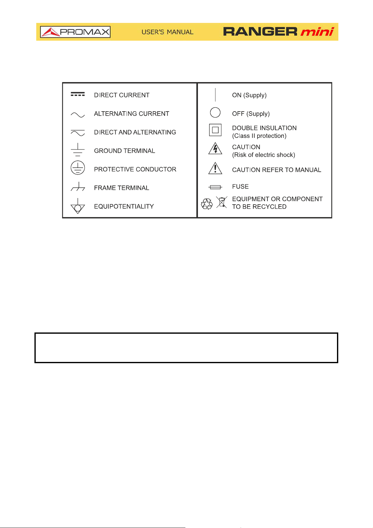
SAFETY SYMBOLS
DESCRIPTIVE EXAMPLES OF OVER VOLTAGE CATEGORIES
* Cat I: Low voltage installations isolated from the mains.
* Cat II: Portable domestic installations.
* Cat III: Fixed domestic installations.
* Cat IV: Industrial installations.
CAUTION: The battery used can present danger of fire or chemical burn if it is
severely mistreat. Do not disassembly, cremate or heat the battery
above 100 °C under no circumstances.
iii
Page 5

TABLE OF CONTENTS
1. INTRODUCTION ........................................................................................ 1
1.1. Description............................................................................................ 1
2. SETTING UP .............................................................................................. 3
2.1. Package Content .................................................................................... 3
2.2. Power ................................................................................................... 3
2.3. Equipment Details .................................................................................. 6
2.4. Switching On / Off .................................................................................. 8
2.5. Icons Table ........................................................................................... 9
2.7. General Settings ...................................................................................10
2.6. Controls ...............................................................................................10
2.8. Firmware Update...................................................................................11
3. MEASUREMENT........................................................................................ 12
3.1. Downstream Spectrum Analyzer..............................................................12
3.2. Upstream .............................................................................................16
3.3. Scan....................................................................................................18
3.4. Tilt ......................................................................................................20
3.5. Voltmeter.............................................................................................22
3.6. Digital Signal Demodulator .....................................................................24
3.7. Analog Signal Demodulator.....................................................................26
4. TOOLS ..................................................................................................... 28
4.1. Edit Channel Plan ..................................................................................28
4.2. Screenshot ...........................................................................................36
4.3. Datalogger - Test & Go ..........................................................................38
5. SPECIFICATIONS .................................................................................... 40
6. MAINTENANCE ........................................................................................ 46
6.1. Instructions for Returning by Mail ............................................................46
6.2. Considerations about the TFT Screen .......................................................46
6.3. Cleaning Recommendations ....................................................................46
iv
Page 6

DIGITAL MULTI SYSTEM ANALYZER
1 INTRODUCTION
1.1 Description
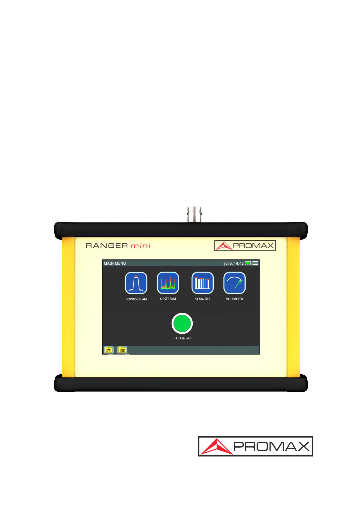
The RANGER mini is the latest introduction in our TV analyzer product range.
It is a multi system analyzer that can work in terrestrial, satellite and cable
transmission systems. It can also be expanded to work with optical fibre.
The RANGER mini has all the functions necessary for an easy installation of any
service. In addition, its intuitive menu, its adjusted weight and strength, makes
it ideal for fieldwork.
The RANGER mini features a 5” professional grade resistive type touch-screen
with excellent brightness and superior image sharpness. It includes a case with
a touch pen to make easy browsing around the menus. The instrument is
powered by an internal rechargeable battery.
RANGER
In the design of the RANGER mini it has dedicated particular attention on
making a practical and precise instrument, as easy to use. The touch interface
allows direct access to different modes of operation and once there, it is easy to
modify any parameter of the measurement.
All this makes the RANGER mini in a magnificent tool for installing and
maintaining all kind of systems: Terrestrial, satellite and HFC (Hybrid Fibber
Cable) / CATV. Being also very useful for testing DOCSIS data transmission
systems.
In addition, the instrument provides Ethernet and USB port slots to connect to
external devices, to download data and to update firmware.
Here are some of the most important functions in the RANGER mini.
Chapter 1: INTRODUCTION 1 September 2018
Page 7
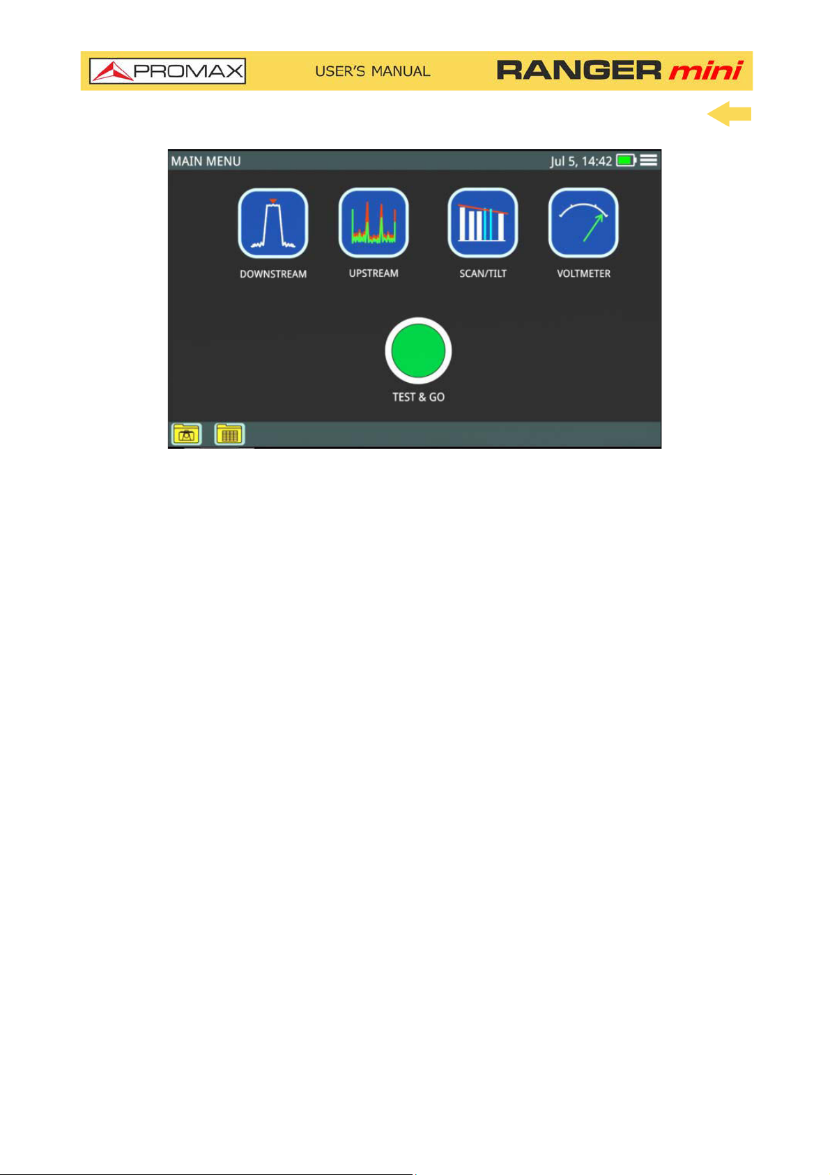
Figure 1.
The Downstream Spectrum Analyzer function provides an analysis of
downstream spectrum in the band between 5 and 2700 MHz. It can demodulate
a signal and show its constellation. Reference level and span can be set by user.
The Upstream function provides an analysis of upstream spectrum in the band
between 5 and 200 MHz. It can easily detect impulse noise.
The Scan function shows the level of all active channels in the channel plan
through a bar chart.
The TILT function measures the tilt in dB obtained from the difference in level
between four carriers. It is useful for equalizing the line.
The Voltmeter function automatically identifies the voltage type (DC or AC) at
the input and the frequency in case of alternating voltage.
In addition, it includes other tools such as datalogger, screenshot, channel plan
editor, etc.
In short, implementation of all these functions into an light instrument,
ergonomic design and robust, makes the RANGER mini into a productive and
efficient fieldwork tool for the installer.
The RANGER mini can be expanded with an optical input allowing field
technicians not only to perform optical power measurements but also to do all
the RFoG measurements using a built-in optical to RF converter.
September 2018 2 Chapter 1: INTRODUCTION
Page 8
2 SETTING UP
2.1 Package Content
Check that your package contains the following elements:
RANGER mini Analyser.
External DC charger.
Power cord for external DC charger
"F" Adapters
•"F" / f - BNC / f Adapter. (2 u.).
•"F" / f - "F" / f Adapter (2 u.).
Carrying case.
Transport suitcase.
Touch pen.
Quick Start Guide.
NOTE: Keep the original packaging, since it is specially designed to protect the
equipment. You may need it in the future to send the analyser to be
calibrated.
2.2 Power
The RANGER mini is powered by a 7.2 V built-in rechargeable LiPo battery of
high quality and long operation time. This equipment can operate on battery or
connected to the mains using a DC adapter.
2.2.1 First Charge
The equipment comes with the battery half charged. Depending on the time
elapsed from first charge and environmental conditions may have lost some of
the charge. You should check the battery level. It is advisable a first full charge.
Chapter 2: SETTING UP 3 September 2018
Page 9
2.2.2 Charging the Battery
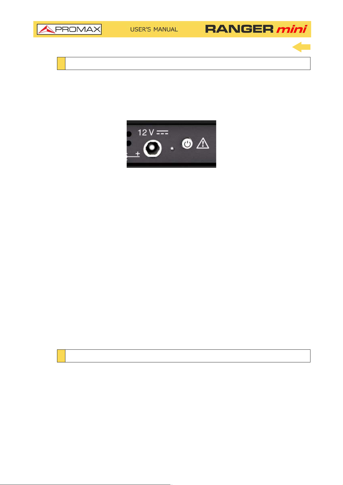
Connect the DC power adapter to the equipment through the power connector
on the downside panel (see figure).
Figure 2. Power input and Charge Indicator + ON / OFF Button
Then connect the DC power adapter to the mains via the mains cord. Ensure that
your mains voltage is compatible with the adapter voltage.
For a fast charging of the battery is necessary to switch off the equipment.
If the equipment is ON, the battery charging will be slower, depending on the
type of work you are doing. When connecting the equipment to the mains the
mains connected symbol appears inside the battery icon.
The led indicator next to the ON/OFF button shows the battery status:
Red: Battery charging.
Off: Battery full charge.
When switching on the equipment, the battery voltage is checked. If the tension
is too weak to start, the equipment does not start up. In this case please charge
the battery immediately.
2.2.3 Charge / Discharge times
Average charging time with the equipment off (fast charge):
3 hours to achieve an 80% charge.
5 hours to achieve an 100% charge.
September 2018 4 Chapter 2: SETTING UP
Page 10

With the equipment on (slow charge):
5 hours to achieve an 80% charge.
8 hours to achieve a 100% charge.
Average discharge time:
With the battery at full charge the average battery time is 4 hours.
With the battery at 80% charge the average battery time is 3 hours.
2.2.4 Usage Tips
The battery is losing storage capacity as you go through its life. Contact your
PROMAX distributor when necessary to replace the battery.
To prolong battery life the user should follow these tips:
In case of providing a long inactivity period of the equipment it is
advisable to make every 3 months a charge / discharge cycle and a
subsequent partial charge (40% aprox.).
It is advisable to keep it in a cool place and away from heat.
You should avoid keeping the battery for a long period of time at full load
or fully discharged.
There is not necessary to wait to fully discharge before a charge because
these batteries have no memory effect.
Chapter 2: SETTING UP 5 September 2018
Page 11

2.3 Equipment Details
Figure 3. Front View.
September 2018 6 Chapter 2: SETTING UP
Page 12
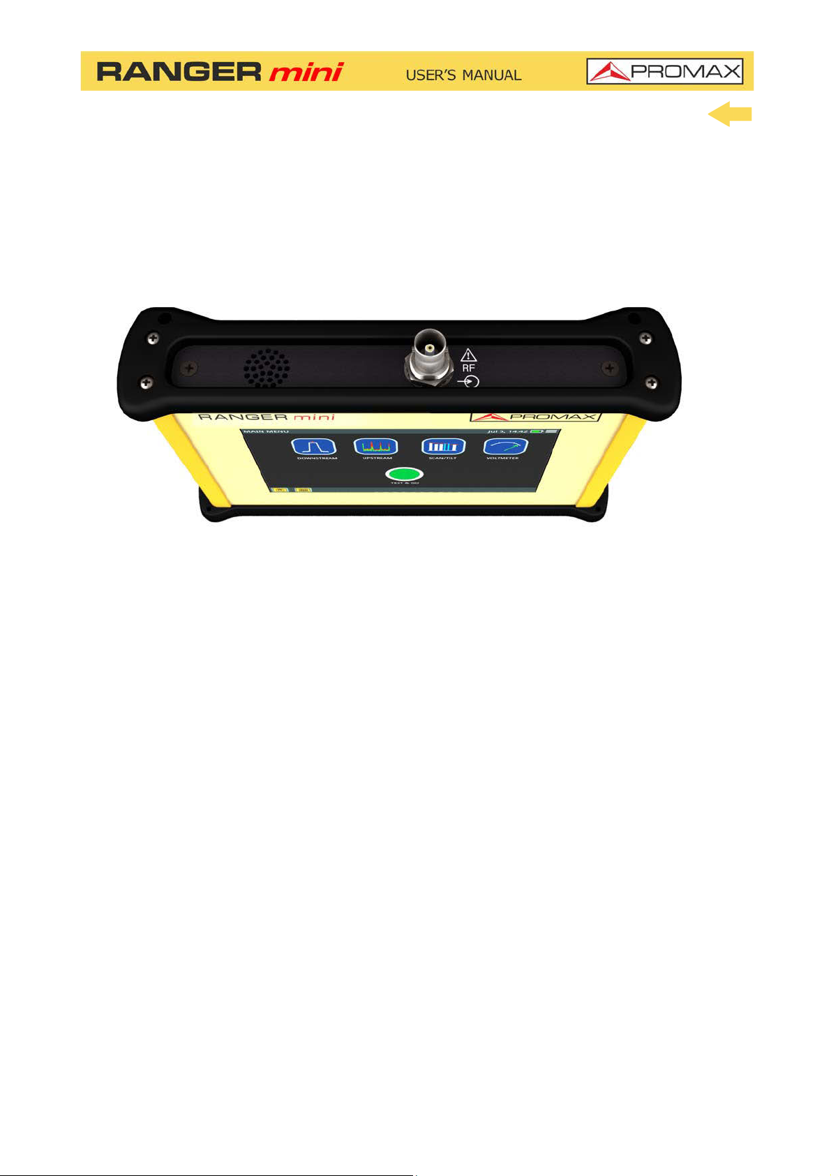
Figure 4. Upside View.
Chapter 2: SETTING UP 7 September 2018
Page 13
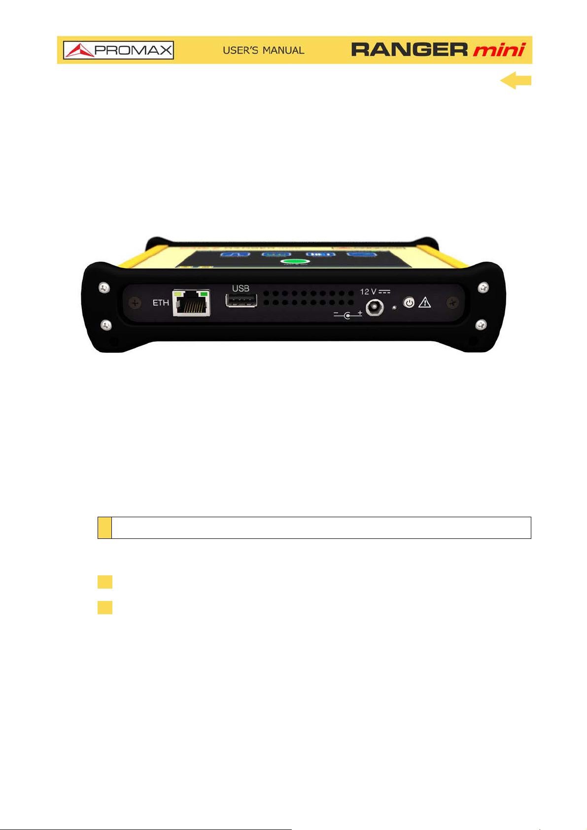
Figure 5. Downside View.
2.4 Switching On / Off
►Switching On:
1 Press the on/off button located on the side of the equipment.
2 The boot screen appears. After the system load, the last screen before
shutdown appears.
September 2018 8 Chapter 2: SETTING UP
Page 14

►Switching Off:
1
There are two options
Option 1: Press the ON/OFF
equipment. A gray screen with a red power off icon will appear. Click
on this icon to turn off the equipment or outside the icon to cancel power
off.
Option 2: Press on the menu icon
corner. Next press on the power off icon at the bottom right corner. A gray
screen with a red power off icon will appear. Click on this icon to turn
off the equipment or outside the icon to cancel power off.
2
The equipment keeps its last status which is recovered when power on
2.5 Icons Table
:
*
button located on the downside of the
located at the screen upper right
.
Figure 6.
*. In case of crashing, press and hold on/off button until it turns off.
Chapter 2: SETTING UP 9 September 2018
Page 15
2.6 Controls
The equipment is operated only using the touch panel.
These actions can be done through the touch panel:
Menu Selection.
Frequency or channel selection or edition.
Frequency or channel scroll.
Reference level scroll.
SPAN selection.
Virtual keyboard writing (numerical and alphabetical).
2.7 General Settings
From the Home screen, clicking on the menu icon you access the general
settings:
Edit channel plan: It allows you to edit a channel plan (refer to "Edit
Channel Plan" chapter).
Language: It allows you to select a language among English, Spanish,
French or German.
Date: It allows you to set date.
Time: It allows you to select time format (12/24) and set time.
Sound: It allows you to set sound level and enable or disable beep.
Auto power off: It allows you to enable or disable auto power off option.
Equipment information: It shows serial number, software version and
other technical data.
Ethernet Configuration: It allows you to select type of connection
(manual/DHCP/Bridge) and network data (IP, Netmask, Gateway, DNS1,
DNS2).
Test&Go configuration: It allows you to set the datalogger settings
when pressing on Test&Go (Scan, DBG or TILT measurements).
September 2018 10 Chapter 2: SETTING UP
Page 16
2.8 Firmware Update
Keep your device up to date for the latest improvements and features. Follow us
on social networks (twitter, Facebook, linkedin, Google+) to get information
about updates and latest news. To update follow these steps:
1 Use a USB flash drive in FAT32 format.
2 Download the file from the download area at PROMAX website
3 Copy the update file (update_usb.tar) to the flash drive root (do not unzip
the file).
4 Turn OFF the RANGER mini and insert the flash drive into the USB port.
5 Turn ON the RANGER mini. The update process starts automatically. Wait
until finished.
6 Remove the flash drive.
7 Press the ON/OFF button for more than 5 seconds until the equipment turns
OFF.
8 Turn ON again.
Chapter 2: SETTING UP 11 September 2018
Page 17

3 MEASUREMENT
3.1 Downstream Spectrum Analyzer
►Description
The Downstream function shows on screen the downstream spectrum of the
signal received through the input connector in the band between 5 and 2700
MHz.
This function shows signals in the frequency band so any problem can be
detected easily. It also measures level and demodulates the tuned signal.
User can adjust span and reference level for the frequency or channel tuned.
User can also select trace type (max hold / min hold), measurement units and
other parameters.
►Operation
1 Connect signal to the input through F/F or F/BNC adapter.
2 From the main screen press on the DOWNSTREAM icon.
3 DOWNSTREAM function opens.
4 Signal can be tuned by one of this ways:
Tuning by CHANNEL: Select one channel from a channel plan.
Tuning by FREQUENCY: Enter the frequency to tune.
Tuning by DBG: Select one DBG group and carrier to tune.
Tuned signal is located by the marker on top.
5 Press DEMOD to demodulate signal and show its constellation.
CHANNEL tuning: It can demodulate signal according to channel
parameters defined in the channel plan.
FREQUENCY tuning: It can demodulate signal according to parameters
defined in settings menu.
6 To show channels with DOCSIS BONDING GROUP carriers select a channel
that belongs to a DBG and press on DBG (for cable transmission according
to DOCSIS standard).
7 Press HOME key to get back to the main screen.
September 2018 12 Chapter 3: MEASUREMENT
Page 18

►Downstream Screen Description
Figure 7. Downstream Spectrum
1 Selected channel. When pressing on it deploys a list of available channels.
2 Frequency selected. When pressing on it pops up a virtual numeric keypad
to edit frequency.
3 DOCSIS Bonding Group selected and carrier.
4 According to signal type:
•Digital signal: Power for channel bandwidth or frequency.
•Analogue signal: Level for channel or frequency selected.
5 Carrier/Noise ratio for channel selected.
6
Full band RF cable power.
7 Marker for selected channel / frequency.
8 Arrows to change reference level.
9 Span lower frequency.
10 Arrows to increase / decrease span. Current span.
11 Bandwidth resolution.
12 Span upper frequency.
Chapter 3: MEASUREMENT 13 September 2018
Page 19

►DOCSIS BONDING GROUP Screen Description
Figure 8. DOCSIS Bonding Group
1 Selected channel. Selected channel should belong to a DBG.
2 Channel plan for the channel selected.
3 Channel bandwidth power.
4 DOCSIS Bonding Group selected. When pressing on, it deploys a list of
available DBGs.
5 DBG carrier selected. When pressing on, it deploys a list of available carriers.
6
Full band RF cable power.
7 Demodulation and constellation for the channel or frequency tuned (for more
details see “Demodulator” chapter).
8 Frequency selected. When pressing on it pops up a virtual numeric keypad
to edit frequency.
9
The graph shows the DBG channels. The marker is on the selected carrier.
September 2018 14 Chapter 3: MEASUREMENT
Page 20

►Options Menu
There are some options at the bottom of the screen:
: Screenshot.
: Back to home screen.
DBG / DOWNSTREAM: It switches between the DOCSIS BONDING
GROUP screen that shows DBG carriers or the Downstream spectrum
signal screen.
DEMOD: Access to Demodulator (refer to "Demodulator " chapter).
►Settings
Click on the MENU icon at the upper right corner to access the Settings
menu. The DOWSTREAM function has these options:
Edit channel plan: It allows you to edit a channel plan and DOCSIS
Bonding Group (refer to "Edit Channel Plan" chapter).
Units: It allows you to select measurement unit for power (dBuV, dBmV,
dBm).
Reference line: It allows you to select the reference line by numbers (-
60 dBmV to +70 dBmv). Reference line allows you to define criteria in
order to quickly accept or refuse channel levels.
Trace: It allows you to select holding type of trace (maximal, minimum).
CTB/CSO: It allows you to set parameters to measure intermodulation
distortion CTB/CSO (Composite Triple Beat / Composite Second Order)
that has a big influence on the net quality.
Frequency step: It allows you to select frequency step (0.25 MHz, 1
MHz, 8 MHz, other value).
Full span maximum frequency: It allows you to select full span
maximum frequency (900 MHz, 2700 MHz, other value).
Tuning frequency demodulation: It allows you to set parameters to
demodulate signal when tuning by frequency. User must select type of
signal, transmission standard (when it is digital) and other related
parameters.
Chapter 3: MEASUREMENT 15 September 2018
Page 21

3.2 Upstream
►Description
The Upstream function shows the upstream spectrum in the band between 5
and 205 MHz allowing to detect impulse noise.
User can adjust span and reference level for the frequency or channel tuned.
►Operation
1 Connect signal to the input through F/F or F/BNC adapter.
2 From the main screen press on the UPSTREAM icon.
3 UPSTREAM function opens.
4 Press HOME key to get back to the main screen.
►Screen Description
Figure 9.
1 Frequency selected. When pressing on it pops up a virtual numeric keypad
to edit frequency.
September 2018 16 Chapter 3: MEASUREMENT
Page 22

2 Level for the selected frequency.
3
Full band RF cable power.
4 Marker in the selected frequency.
5 Arrows to change reference level.
6 Span lower frequency.
7 Arrows to increase / decrease span. Current span.
8 Bandwidth resolution.
9 Span upper frequency.
►Options Menu
There are some options at the bottom of the screen:
: Screenshot.
: Back to home screen.
►Settings
Click on the MENU icon at the upper right corner to access the Settings
menu. The UPSTREAM function has these options:
Frequency step: It allows you to select full span maximum frequency
(0.25 MHz, 1 MHz, 8 MHz, other value).
Full span maximum frequency: It allows you to select full span
maximum frequency (900 MHz, 1700 MHz, other value).
Chapter 3: MEASUREMENT 17 September 2018
Page 23

3.3 Scan
►Description
The SCAN function shows on screen signal level in graphic bar format for each
one of the active channels in the selected channel plan.
►Operation
1 Connect signal to the input through F/F or F/BNC adapter.
2 From the main screen press on the SCAN/TILT icon.
3 SCAN function opens. It shows a bar graph representing signal level or
power for each one of the active channels in the channel plan
4 Press DEMOD to demodulate signal.
5 Press HOME key to get back to the main screen.
►Screen Description
Figure 10.
1 Selected channel. When pressing on, it deploys a list of available channels.
September 2018 18 Chapter 3: MEASUREMENT
Page 24

2 Frequency for the channel selected.
3 DOCSIS Bonding Group selected and carrier (if any).
4 According to signal type:
•Digital signal: Power for channel bandwidth or frequency.
•Analogue signal: Level for channel or frequency selected.
5 Carrier/Noise ratio of the channel.
6
Full band RF cable power.
7 Marker for selected channel / frequency.
8 Arrows to change reference level.
9 Span lower frequency.
10 Arrows to increase / decrease span. Current span.
11 Bandwidth resolution.
12 Span upper frequency.
► Options Menu
There are some options at the bottom of the screen:
: Screenshot.
DATALOGGER: It creates a datalogger with measurement data.
: Back to home screen.
TILT: Access the TILT function.
DEMOD: Demodulator (refer to "Demodulator" chapter).
Chapter 3: MEASUREMENT 19 September 2018
Page 25

►Settings Menu
Click on the MENU icon at the upper right corner to access the Settings
menu. The SCAN function has these options:
Edit channel plan: It allows you to edit a channel plan and DBG (refer to
"Edit Channel Plan" chapter).
Units: It allows you to select a mesurement unit for power (dBuV, dBmV,
dBm).
Reference Line: It allows you to select the reference line by numbers
(-60 dBmV to +70 dBmv). Reference line allows you to define criteria in
order to quickly accept or refuse channels levels.
Threshold:
CTB/CSO: It allows you to set parameters to measure intermodulation
distortion CTB/CSO (Composite Triple Beat / Composite Second Order)
that has a big influence on the net quality.
3.4 Tilt
►Description
The TILT function is a test to measure tilt in order to equalize the line. TILT is
the difference in amplitudes between the minimum and maximum frequency
that the system can compensate.
The TILT function displays on-screen, graphically and numerically, the
difference in level between any four frequencies previously defined as pilots.
This function works for upstream and downstream band.
Typically, CATV networks transmit pilot signals at the beginning and at the end
of the band. These pilots signals and other intermediate signals can be tuned
simultaneously on the screen. By this way you can evaluate the losses tilt and
therefore readjust equalizers of the amplifiers in order to compensate these
losses and ensure a flat response along the band.
It allows you to threshold level.
September 2018 20 Chapter 3: MEASUREMENT
Page 26

►Operation
1 Connect signal to the input through F/F or F/BNC adapter.
2 From the main screen press on the SCAN/TILT icon.
3 Press on TILT option at the bottom of the screen.
4 TILT function opens.
5 Press on the lower right corner to switch between Upstream and
Downstream band.
6 Press HOME key to get back to the main screen.
►Screen Description
Figure 11.
1 It shows pilot signals frequency and power. Press on frequency to change its
value.
•P1/P4: End pilot signals.
•P2/P3: Intermediate pilot signals.
2 TILT: Inclination rate in dB per MHz.
3 Power difference between P1 and P4.
4 Full band RF cable power.
Chapter 3: MEASUREMENT 21 September 2018
Page 27

5 Arrows to change reference level.
6 Bar graph showing signal level for each pilot signal and TILT.
►Options Menu
There are some options at the bottom of the screen:
: Screeenshot.
DATALOGGER: It creates a datalogger with measurement data.
: Back to home screen.
SCAN: Access the SCAN function.
UPSTREAM/DOWNSTREAM: It allows you to switch between upstream
and downstream band. The current band appears on the top of the left
corner.
►Settings Menu
Click on the MENU icon at the upper right corner to access the Settings
menu. The TILT function has these options:
Units: It allows you to select a mesurement unit for power (dBuV, dBmV,
dBm).
3.5 Voltmeter
►Description
The VOLTMETER function automatically identifies the voltage type (DC or AC) at
the input and the frequency in case of alternating voltage.
It also allows to supply voltage to a LNB in several bands and polarizations in
case of working in satellite band.
►Operation
1 Connect signal to the input through F/F or F/BNC adapter.
2 From the main screen press on the VOLTMETER icon.
3 VOLTMETER function opens.
4 Press HOME key to get back to the main screen.
September 2018 22 Chapter 3: MEASUREMENT
Page 28

►Screen Description
Figure 12.
1 RF-PWR: Full bandwidth power.
2 Vin DC: DC input voltage.
3 Vin AC: AC input voltage and frequency.
4 Iout: Current out.
5 Voltage supply for the LNB:
•ON Voltage: Check the box to enable voltage supply.
•13 Volts / 18 Volts: Check the box to select between polarization
(vertical=13 V; horizontal=18V).
•22 kHz: Commutation tone. Check the box to change band (0 kHz=low;
22 kHz=high).
►Options Menu
There are some options at the bottom of the screen:
: Screeenshot.
: Back to home screen.
Chapter 3: MEASUREMENT 23 September 2018
Page 29

►Settings Menu
Click on the MENU icon at the upper right corner to access the Settings
menu. The VOLTMETER function has these options:
Units: It allows you to select measurement unit for power (dBuV, dBmV,
dBm).
3.6 Digital Signal Demodulator
►Description
Demodulator provides the most important measurements technicians need to
assess digital QAM channel quality. Constellation diagram is a simple and
graphical way to identify signal impairments which impact MER and ultimately
BER. An ideal QAM channel for example will be represented by a set
(constellation) of very sharp dots. These dots will become small dot clouds to
indicate the presence of noise or other signal degradation sources. In addition
to constellation diagram it also measures MER, preBER and postBER
simultaneously with the spectrum trace.
►Operation
DEMODULATOR is available for digital signals of functions SPECTRUM
ANALYZER and SCAN
.
1 Select channel or frequency and tune it.
2 Press on "DEMOD" option.
September 2018 24 Chapter 3: MEASUREMENT
Page 30

►Screen Description
Figure 13.
1 Demodulated Signal Data.
MER for tuned channel.
pre-BER (BER before correction).
post-BER (BER after correction).
Transmission standard. Press to switch.
FFT Mode.
Press on “i” box to obtain more info.
2 Constellation Diagram (I-Q diagram).
►Options Menu
There are some options at the bottom of the screen:
CLR IQ:
It clears constellation
.
Back to previous screen.
Chapter 3: MEASUREMENT 25 September 2018
Page 31

3.7 Analog Signal Demodulator
►Description
The equipment can measure video carrier signal level, Video/Audio and C/N
ratio, HUM and intermodulation products from an analogue signal. This is all
shown alongside the screen together with the spectrum analyzer graphic. The
HUM is buzz at low frequency modulation that affects video analogue carriers,
producing a distinctive hum. The HUM value up to 2% is considered acceptable.
Above this value is not acceptable and it should take appropriate
countermeasures.
►Operation
This function is available for analogue signals in DOWNSTREAM and SCAN.
1 Select analogue channel or frequency and tune it.
2 Press on "DEMOD" option.
3 To set measurement parameters for intermodulation products (CTB/CSO)
access the settings menu at the upper right corner.
September 2018 26 Chapter 3: MEASUREMENT
Page 32

►Screen Description
Figure 14.
1 Analogue Video Carrier / HUM.
Video c.LVL: Level of video carrier.
Audio c.LVL: Level of audio carrier.
V/A: Video/Audio ratio.
C/N: Carrier/Noise ratio.
HUM: Audio carrier.
CTB/CSO: Intermodulation product measurement. Press to enable/
disable.
Audio OFF/ON: It enables / disables audio and to set audio level.
Chapter 3: MEASUREMENT 27 September 2018
Page 33

4 TOOLS
4.1 Edit Channel Plan
►Description
Channel plan editor allows to edit and create channel plans, and also to edit DBG
(Docsis Bonding Group) channels.
►Operation
Channel plan editor is available for tools DOWNSTREAM and SCAN .
1 From the tool screen access settings menu by pressing on .
2 Press on "Edit Channel Plan" option to access channel plan editor.
3 To select a channel plan press on the channel plan name to dropdown a list
of available channel plan. Select one of them.
4 Press on CH to switch between tune by channel or frequency.
5 Next to CH box press on the channel or frequency value to edit and select a
specific channel or frequency. You can also select a channel moving along
the channel plan list using the side scroll bar. The selected channel has a blue
background.
6 Press on a parameter of the channel to edit. If the parameter is a number,
it shows up a virtual keyboard to edit that value. If the parameter value is a
text, you should press several times on it to switch among different options.
7 Once edited, press on Return key and it appears a window with options:
"Save" (it saves changes and exits), "Don't save" (it does not save changes
and exits), "Cancel" (it does not saves changes and does not exit).
September 2018 28 Chapter 4: TOOLS
Page 34

►Screen Description
Figure 15.
1 Channel plan selected. Press on this box to select another channel plan.
2 Go to: Press on this box to switch between CH (channel) and FR (frequency)
and to select a channel or frequency.
3 Channel table. Press on a paremeter to edit o switch among options.
Parameters on channel table are:
Active: To enable or disable channels.
CH: Channel name.
FR (MHz): Channel frequency (MHz).
ΔF (MHz): Offset of tuned frequency for channel (MHz).
BW (MHz): Bandwidth for channel.
A/D: It indicates if channel is analogue (A) or digital (D).
System: It indicates transmission standard (DVB-T/T2, ISDB-T, ITU
*
J83.B, PAL/NTSC/SECAM, DVB-C/C2)
.
ΔF Audio (MHz): Offset of tuned frequency for audio (MHz).
DBG: It shows primary carrier for DBG.
*. Some standards may appear with an asterisk that means it is not available yet but it will be in
next firmware updates.
Chapter 4: TOOLS 29 September 2018
Page 35

►Options Menu
There are some options at the bottom of the screen:
EDIT DBG: Opens the DBG editor screen (see next section).
: Back to main screen.
►Settings Menu
Click on the MENU icon at the upper right corner to access the Settings
menu. The EDIT CHANNEL PLAN function has these options:
Add new channel: It adds a new channel for a channel plan (for standard
channel plans it is not allowed).
Remove channel: It removes selected channel.
New channel plan: It creates a new channel plan. There are three options
(see next section:
•Create a channel plan from an existing one.
•Create automatically a channel plan from HFC network.
•Create a channel plan from void pattern.
Remove channel plan: It removes current channel plan.
Import standard plan: It allows you to import a standard channel plan.
September 2018 30 Chapter 4: TOOLS
Page 36

►EDIT DOCSIS BONDING GROUP Screen Description
Figure 16.
Edit DOCSIS Bonding Group: Press on the box below to select a DBG to
edit.
Add channel: Press on the box next to “Add channel” to select one
channel. Then press on ADD to add it to DBG.
Remove channel: Press on one channel in the box to select it and then
press on REMOVE to remove it from DBG.
Primary Carrier: Press on Primary Carrier column to define if that channel
is a primary carrier (YER or NO).
Chapter 4: TOOLS 31 September 2018
Page 37

►Create a Channel Plan from an existing one
Figure 17.
September 2018 32 Chapter 4: TOOLS
Page 38

Figure 18.
1 Press on box "Model" to select a channel plan as a model to create a new one.
2 Press on box "Name" to give a name to the new channel plan.
3 Press "OK" to create a new channel plan or "Cancel" to exit.
4 At the next screen, press on "Add Channel", "Remove Channel" to edit
channel plan. When finish, press on "Save channel plan" to save changes or
"Cancel" to exit without saving.
Chapter 4: TOOLS 33 September 2018
Page 39

►Create automatically a channel plan from HFC network
Figure 19.
September 2018 34 Chapter 4: TOOLS
Page 40

Figure 20.
1 Connect to the HFC network.
2 Press on box “Model” to select a channel plan as a model to create a new one.
3 Press on “Start measuring”.
4
When finish press on "Name" box to edit the channel plan name. Press on
"Save channel plan" to save changes or "Cancel" to exit without saving
.
Chapter 4: TOOLS 35 September 2018
Page 41

►Create a new Channel Plan from scratch
1 Press on box "Name" to give a name to the new channel plan.
2 At the next screen, press on “Add Channel”, “Remove Channel” to edit
channel plan. When finish, press on “Save channel plan” to save changes or
“Cancel” to exit without saving.
4.2 Screenshot
►Description
It saves a screenshot of current screen that can be downloaded to a USB
flashdrive.
Figure 21.
September 2018 36 Chapter 4: TOOLS
Page 42

►Operation
Figure 22.
Screenshot is available almost for all functions.
1 To take a screenshot press on photo camera icon at the lower left
corner.
2 It pops up a window with a screenshot miniature and some options: “Save
and close”, “Save and go to gallery” and “Cancel”. Press your option.
3 To access the photo gallery with all the screenshots, from home screen press
on icon
4 Inside Photo Gallery, screenshots are classified by function.
5 Press on the corresponding folder and then on the image to view the
screenshot.
6 To copy screenshots connect a USB flashdrive on USB port and press on
menu option
7 To remove a folder, go to the Photo Gallery, press on option menu and
then on “Remove”. Now select the folder to remove and confirm.
at the lower left corner.
and the on “Save in USB”.
Chapter 4: TOOLS 37 September 2018
Page 43

8 To remove a single screenshot, see the screenshot fullscreen, press on
option menu
and then on “Remove” and confirm.
4.3 Datalogger - Test & Go
►Description
Datalogger function can made and save automatically several measurements
depending on the selected function, including signal level and channel power,
carrier/noise, BER and MER for all channels in a specific channel band.
The Test & Go function is a shortcut in the home screen that starts a datalogger
set by default in the Test&Go configuration option.
►Operation
Figure 23.
1 To start datalogger, select a function and press on DATALOGGER at the left
lower corner screen.
2 You can also press on "Test & Go" at the home screen. In this case you must
select the datalogger by default through the option Test&Go configuration
from the settings menu in the main screen.
September 2018 38 Chapter 4: TOOLS
Page 44

3 A window opens with several setting options. You can edit boxes (name,
location, threshold...) when pressing on it. Check the box to select
measurements and press on “Start Measuring” or “Cancel”.
4 It starts datalogger.
5 After finish, press on "Save and close", "Save and go to datalogger" or
"Cancel".
6 To access datalogger library, go to home screen and press on icon at the
lower left corner.
7 In the library each datalogger is classified by function.
8 Press on any folder, then press on the specific datalogger to see data.
9 To remove a folder with dataloggers or a single datalogger, press on the
menu option and then on “Remove”. It shows a window where to select
a folder or datalogger to remove. Select and accept.
10 To copy a folder with dataloggers or a single datalogger to a USB memory
in first place insert a USB memory in the USB slot. Press on menu option
and then press on “Save on USB”. It shows a window with the path where
are the files to be copied. Confirm to save.
Chapter 4: TOOLS 39 September 2018
Page 45

5 SPECIFICATIONS
5.1 Spectrum Analyzer
►Frequency
Parameter Value Additional Data
Tuning Range From 5 to 2700 MHz
Tuning Mode By frequency or by channel
Bandwidth resolution 230 kHz, 2 MHz
Frequency Tuning Resolution 10 kHz
Accuracy 20 ppm
Sweep time 600 ms full band
►Amplitude
Parameter Value Additional Data
Measuring range -50 dBmV to 60 dBmV
Measuring range in screen 50 dB
Max Input level 70 dBmV
Resolution 0.1 dB
Accuracy ± 2 dB
Input impedance 75 Ohms
Units dBmV, dBuV, dBm
►Frequency Tuning Mode
Parameter Value Additional Data
Level - 50 dBmV to 60 dBmV Peak detector level measurement
from marker
Audio demodulation Analog FM
C/N >50 dB for level >10 dBmV Selectable noise frequency marker
HUM 1-15 % , ± 1 % accuracy For FM or CW carriers
►DIGITAL Spectrum Analyzer (Cable and Terrestrial)
Parameter Value Additional Data
Tuning Range From 10 to 2700 MHz
Power From –40 dBmV to 60 dBmV Power measurement in the channel
bandwidth by integration method
Compatibility DVB-C/C2/T/T2,I.J43 Annex B, ISDBT,
SR 1000-7000 ksym/s
MER From 24 dB to 43 dB for QAM16, 32,
BER Pre BER (Before RS): From 10 E-2 to
Constellation Diagram DVB-C/C2/T/T2,I.J43 Annex B, ISDBT,
J.382
64, 128, 256 and QPSK
10 E-10
J.382
Accuracy ± 2 dB
Post BER (After FEC): From 10 E-2 to
10 E-10
September 2018 40 Chapter 5: SPECIFICATIONS
Page 46

Parameter Value Additional Data
Lock range -20 dBmV to 60 dBmV
►ANALOG Spectrum Analyzer
Parameter Value Additional Data
Tuning Range From 10 to 2700 MHz
Video Carrier Signal Level From –45 dBmV to 60 dBmV
Audio Carrier signal level, A/V 0- 30 dB (for PAL, SECAM or NTSC
C/N 48 dB for input level > 10 dBmV
HUM (over audio carrier) 1-15%, 1% accuracy
CTB/CSO 60 dB dynamic range. (In channel
Sound broadcast FM demodulation from
standard)
± 3 dB accuracy
with removed carrier or out of channel
selecting a not used channel)
internal speaker
►DOCSIS
Parameter Value Additional Data
Dowstream Analyzer:
Power and Spectrum DOCSIS 2.0/3.0/3.1
MER / BER DOCSIS 2.0/3.0/3.1 (MER estimated in 3.1)
Constellation DOCSIS 2.0/3.0
DBG Tuning 16 x 8 channels
Upstream Analyzer 5 - 200 MHz
►SATELLITE Spectrum Analyzer
Parameter Value Additional Data
Tuning Range 950 - 2150 MHz
Spectrum and Power DVB-S/S2
MER / BER DVB-S/S2
Constellation DVB-S/S2
LNB Supply 12 / 15 / DiSEqC
►Configuration Menu
Parameter Value Additional Data
Channel Plan Ye s
Standard TV Channel plans CCIR,EIA,HRC,IRC,OIRL,FCC up to 10
Customized Channel plan Up to 30
Units dBmV, dBuV, dBm
Reference Line from –60 dBmV to 60 dBmV
Trace normal, max hold and min hold
Frequency step from 10 kHz to 100 MHz
Top Frequency 900 MHz, 1800 MHz or selectable
Chapter 5: SPECIFICATIONS 41 September 2018
Page 47

5.2 Scan
►Frequency
Parameter Value Additional Data
Tuning Range Full frequency band occupied by
selected Channel plan
Tuning Mode by channel
Bandwidth resolution 230 kHz
►Amplitude
Parameter Value Additional Data
Dynamic range -50 dBmV to 60 dBmV
Screen range: 50 dB
Max Input level: 70 dBmV
Resolution: 0.1 dB
Accuracy: ± 2 dB
Input impedance: 75 Ohms
Units: dBmV, dBuV, dBm
►Measurements: DIGITAL Channel
Parameter Value Additional Data
Power From –40 dBmV to 60 dBmV Power measurement in the channel
bandwidth by integration method at
the marker. Represented by vertical
blue bars
►Channel Demodulation
Parameter Value Additional Data
Compatibility DVB-C/C2/T/T2,I.J43 Annex B, ISDBT,
J.382
SR 1000-7000 ksym/s
MER From 24 dB to 43 dB for
QAM16,32,64,128,256 and QPSK
BER Pre BER (Before RS): From 10 E-2 to
10 E-10
Constellation Diagram DVB-C/C2/T/T2,I.J43 Annex B, ISDBT,
J.382
Lock range -20 dBmV to 60 dBmV
Accuracy ± 2 dB
Post BER (After FEC): From 10 E-2 to
10 E-10
►Measurements: Analog TV Channel
Parameter Value Additional Data
Video Carrier Signal Level From –45 dBmV to 60 dBmV Represented by vertical white bars
September 2018 42 Chapter 5: SPECIFICATIONS
Page 48

►Channel Demodulation
Parameter Value Additional Data
Audio Carrier signal level, A/V 0- 30 dB (for PAL, SECAM or NTSC
C/N 48 dB for input level > 10 dBmV
HUM (over audio carrier) 1-15%, 1% accuracy
CTB/CSO 60 dB dynamic range. (In channel
Sound broadcast FM demodulation from
standard)
± 3 dB accuracy
with removed carrier or out of channel
selecting a not used channel)
internal speaker
►Configuration Menu
Parameter Value Additional Data
Channel Plan Ye s
Standard TV Channel plans CCIR,EIA,HRC,IRC,OIRL,FCC up to 10
Customized Channel plan Up to 30
Units dBmV, dBuV, dBm
Reference Line from –60 dBmV to 120 dBmV
Units dBmV, dBuV, dBm
Reference Line from –60 dBmV to 120 dBmV
Thresholds Max and Min limits for quality evalua-
tion
5.3 Tilt
►Downstream
Parameter Value Additional Data
Frequency: Four selectable tuning frequencies
(pilots) from 45 MHz to 1700 MHz
Bandwidth resolution 230 kHz
Frequency Tuning resolution 10 kHz
Dynamic range -50 dBmV to 60 dBmV
Screen range 50 dB
Max Input level 70 dBmV
Resolution 0.1 dB
Measurements Level of four selected frequencies ±0 to 30 dB/ MHz (Tilt) between two
Resolution 0.1 dB
►Upstream
Parameter Value Additional Data
Frequency: Four selectable tuning frequencies
(pilots) from 45 MHz to 1700 MHz
selected pilots
Chapter 5: SPECIFICATIONS 43 September 2018
Page 49

Parameter Value Additional Data
Bandwidth resolution 230 kHz
Tuning resolution 10 kHz
Dynamic range -50 dBmV to 60 dBmV
Screen range 50 dB
Max Input level 70 dBmV
Resolution 0.1 dB
Measurements Level of four selected frequencies ±0 to 30 dB/ MHz (Tilt) between two
selected pilots
Resolution 0.1 dB
►Configuration Menu
Parameter Value Additional Data
Units dBmV, dBuV, dBm
Select two pilots for Tilt Pbottom / Ptop
5.4 Input Voltage and RF Power Meter
►RF Power Measurement
Parameter Value Additional Data
Frequency band 5-1700 MHz
Power accuracy: ± 3 dB
►Input Voltage Measurement
Parameter Value Additional Data
VDC 5 - 100 V
VAC 1 - 30 V
Frequency measurements from 10 Hz to 200 Hz, ±2 % accuracy
LNB Supply Voltage 13 V, 18 V, 13 V + 22 kHz, 18 V + 22
kHz
►Configuration Menu
Parameter Value Additional Data
Units: dBmV, dBuV, dBm
September 2018 44 Chapter 5: SPECIFICATIONS
Page 50

5.5 General Specifications
►Inputs and Outputs
Parameter Value Additional Data
RF Interchangeable F, BNC, IEC
Optical Yes
USB Available USB type A female
Ethernet Available
VDC Available
Touch Monitor Display Available
►Mechanical Features
Parameter Value Additional Data
Dimensions 177 x 117 x 30 mm
Weight 0.7 kg
►Power Supply
Parameter Value Additional Data
Internal battery 7,2 V; 3 Ah Li-Po
Battery Operation Time > 4 hours in continuous mode
Recharging Time 3 hours up to 80% (turned off)
External Voltage 12 V DC
Consumption 12 W
Auto Power Off Available
►Operating Environmental Conditions
Parameter Value Additional Data
Altitude Up to 2.000 m
Temperature range From 5ºC to 40ºC
Max. Relative Humidity 80 % up to 31ºC, decreasing lineally up to
NOTE:
Equipment specifications are set in these environmental operating conditions. Operation outside
these specifications are also possible. Please check with us if you have specific requirements.
50% at 40ºC
►Included Accesories
Parameter Value Additional Data
DC Adapter, DC car adapter, F
connector (2), transport case,
suitcase, Quick reference guide
Chapter 5: SPECIFICATIONS 45 September 2018
Page 51

6 MAINTENANCE
6.1 Instructions for Returning by Mail
Instruments returned for repair or calibration, either within or out of the
warranty period, should be sent with the following information: Name of the
Company, name of the contact person, address, telephone number, receipt (in
the case of coverage under warranty) and a description of the problem or the
service required.
6.2 Considerations about the TFT Screen
This paragraph offers key considerations regarding the use of the colour screen,
taken from the specifications of the manufacturer.
In the TFT screen, the user may find pixels that do not light up or pixels that are
permanently lit. This should not be regarded as a defect in the TFT. In
accordance with the manufacturer quality standard, 9 pixels with these
characteristics are considered admissible.
Pixels which are not detected when the distance from the surface of the TFT
screen to the human eye is greater than 35 cm, with a viewing angle of 90°
between the eye and the screen should not be considered manufacturing defects
either.
It is advisable a viewing angle of 15° in the 6.00 o’clock direction in order to
obtain the optimum visualization of the screen.
6.3 Cleaning Recommendations
The equipment consists of a plastic case and a TFT screen. Each element has its
specific cleaning treatment.
►Cleaning the TFT Screen
The TFT screen surface is VERY DELICATE. It has to be cleaned with a soft fabric
cloth (cotton or silk), always making the same move from left to right and from
top to bottom, without putting pressure on the screen.
The TFT screen has to be dry-cleaned or with a product specifically designed for
TFT screens, by slightly dampening the cloth. NEVER use tap or mineral water,
alcohol or conventional cleaning products, because they contain components
that can damage the screen.
Turn off the equipment to locate dirt on the screen. After cleaning, wait a few
seconds before turning on.
September 2018 46 Chapter 6: MAINTENANCE
Page 52

►Cleaning the Plastic Case
The equipment has to be disconnected before cleaning the case.
The case must be cleaned with a solution of neutral soap and water, using a soft
cloth dampened with this solution.
Before use, the equipment has to be completely dry.
Never clean with abrasive soaps, chlorinated solvents or aromatic hydrocarbons.
These products may degrade the case.
Chapter 6: MAINTENANCE 47 September 2018
Page 53

PROMAX ELECTRONICA, S.L.
 Loading...