

Page 1

TV & SAT LEVEL METER
1 GENERAL INFORMATION
1.1 Description
- 77 -
PROLINK-7
PROLINK-7
The
of frequencies covered - 5 to 862 MHz and 920 to 2150 MHz - makes it an excellent
instrument for
Television', where the subband tuning margin, from 5 to 45 MHz, enables the user to
carry out tests on the return channel),
('Very Small Aperture Terminal')
analysis (38.9 MHz).
The
adopting, apart from the characteristic parameters of the standard, the correcting
automatic system to obtain in all the cases an accurate measuring of the input signal
level. It admits any TV system (
directly with
carrier-to-noise ratio (
modulation: QPSK, QAM or OFDM). Being a multistandard instrument, it can be
efficiently used in any country of the world. Its accuracy and reliabilit y mee t the needs
of the most demanding users.
Its design featuri ng a microprocess or-based
OSD
the
and parameters configured by the user, enables him to adapt its
with
to optimise the process of measurement; for example, continuous frequency
the correction of linearity and flatness errors, the appropriate selection of the
attenuators, and the automatic cut-off after the device has been inactive for a certain
period of time. To enhance its convenience of use, it has
different measuring configurations: name of broadcasting station, frequency, units of
measurement, standard, power supply to external units, frequency of the sound
subcarrier and kind of measurement (level, V/A or digital carrier). Moreover, the
DATALOGGER
(99 configurations x 99 different signals) that makes it much easier to test systems in
which a large number of measurements have to be made, and enables further
processing of all the information acquired.
absolute values and, optionally, on an analogue bar shown superimposed on the
monitor image, that facilitates the de tec tion of th e m ax imu m level. Mo re ov er, in the LV
sound mode, the loudspeaker emits a tone whose frequency depends on the level of
the signal received, which is very useful when installing antennas. It is also possible
to display on screen the line synchronism pulse like on an oscilloscope screen.
('On Screen Display') function that displays on screen the different functions
remarkable ease
A modern µP automatically handles a large part of the operations necessary
The signal level measured is indicated numerically on an LCD display, in
FM radio, terrestrial TV, cable TV (CATV
PR OLI NK-7 includes the main TV standards: M , N, B, G , I, D , K a nd L,
digital TV
function permits the acquisition and storage of up to
is the most advanced of the
satellite TV, MMDS microwave links, VSAT
systems, digital TV
PAL, SECAM
signals for which it provides directly the measuring of power,
C/N
) and bit error rate (
.
PROMAX
NTSC
and
BER
) (this last according to the required
intelligent control system
level meters. The range
, 'Community Antenna
intermediate frequency
and
) and allows the user to work
a dvance d c apabilities
99 memories
to store the
9801 measures
along with
synthesis
,
06/97 PROLINK-7
Page 2

- 78 -
The selection of sound subcarrier is automatic, depending on the standard, or
tunable between 4 and 9 MHz. When decoding TV sound it is possible to choose
between the
includes a
NARROW
NICAM
and
WIDE
filter to obtain the best carrier discrimination. It
decoder that provides the indication of the bit error rate (
BER
) and
the type of sound received (STEREO/DUAL). Moreover, the possibility to com mute the
channel that is delivered to the loudspeaker enables the user to check the sound
stereo and dual.
The
PROLINK-7
level is only one of its multiple functions.
of the
line synchron ism pulse
A
EUROCONNECTOR
is a highly advanced instrument in which the measuring of
Teletext, spectrum a nalyse r function
, display
are so me of t he pos sibilities p rovided.
has been also i ncl uded wit h i nput /out put of audi o/ vi deo.
The o utput of sate llite video on base band allows the use of D2-MAC decoders and
others.
The instrument is mains powered or with a rechargeable battery, and it is also
possible to supply different voltages to the external unit (
terrestrial TV, and
13 V / 15 V / 18 V / 13 V + 22 kHz / 15 V + 22 kHz / 18 V + 22kH z
13 V / 15 V / 18 V / 24 V
satellite TV).
It also incorporates a
RS-232C
interface which enables the user to connect the
instrument to a PC for data recording, remote-control of the instrument and to a printer
in order to print out the measurements.
Its constructi on is bas ed on
('Intelli gent Module Interc onnection') tec hnology,
IMI
developed by the PROMAX R & D team, that allows easy updating of the instrument
by incorporating new functions and optional cards with a high degree of flexibility.
06/97 PROLINK-7
Page 3

- 79 -
1.2 Specifications
TUNING
Spe ctrum bands
Sub-band
VHF
UHF
SAT
FM
IF input
Tuning mode s
Indicator
Resolution
Automa tic se arch
Memory
Da ta Logger function
LEVEL MEASUREMENT
Measurement range
Terrestrial TV & FM bands
S a te llite T V ba n d
SPECTRUM mode
S a te llite ba n d
T erre stria l bands
Bandwidth
Reading
Digital
Analogue
Attenuators
T erre stria l bands
S a te llite ba n d
Input impeda nce
Measurement bandwidth
IF ba ndwidth
Audible indicator
Accuracy
Sub-band
T erre stria l bands
S a te llite ba n d
RF output
Inse rtion losse s
Variable span
Te rre st. bands
S a te llite ba n d
F ull sp a n
Terrestrial
Satellite
Digital frequency synthesis. Continuous tuning from 5 to
862 MHz and from 920 to 2150 MHz.
Sub-band 5 - 45 MHz
LOW band 45 - 170 MHz
HIGH band 170 - 450 MHz
UHF band 450 - 862 MHz
SAT TV 1st IF 920 - 2150 MHz
FM band 87 - 109 MHz
38.9 MHz
Frequency, channel or memory. On demand channel
table
LCD alphanumeric display
62.5 kHz in TV and FM
500 kHz in SAT
Selectable threshold
99 configurations
9801 measurements
20 dBµV to 130 dBµV (10 µV to 3.16 V)
30 dBµV to 120 dBµV (31.6 µV to 1 V)
30 dBµV to 120 dBµV (31.6 µV to 1 V)
20 dBµV to 130 dBµV (10 µV to 3.16 V)
100 kHz, 230 kHz or 1 MHz selectable
100 kHz, 230 kHz or 4 MHz selectable
1 MHz
4 MHz
Auto-range or manual selection
Absolute value calibrated in dBµV, dBmV, dBm or V
Relative value: analogue bar on the screen
0 to 80 dB, AUTO (10 dB steps)
0 to 70 dB, AUTO (10 dB steps)
75 Ω (BNC)
230 kHz (terrestrial bands) 4 MHz (satellite band)
(maximum band ripple 1 dB).
300 kHz (TV) 27 MH z (SAT)
A tone that varies with the signal level
±1.5 dB (50-120 dBµV and 5-45 MHz) (22ºC ± 5ºC)
±1 dB (30-120 dBµV and 48.25-861 MHz) (22ºC ± 5ºC)
±1 dB (40-100 dBµV and 920-2050 MHz) (22º C ± 5ºC)
75 Ω (BNC)
22 dB typical, with 10 dB RF INPUT attenuator
06/97 PROLINK-7
Page 4

Ma ximum signa l
RF input
From DC to 100 MH z
From 5 to 2150 MHz
Vide o input
MONITOR DISPLAY
CRT
Synchronism and Burst
Spe ctrum function
M onitor type
Sensitivity
50 / 6 0 H z synchronism
S a te llite ba n d
T erre stria l band
VIDEO SIGNAL
Exte rnal video input
Sensitivity
Vide o output
Base ba nd video SA T output
- 80 -
50 V rms (powered by the mains supply)
30 V rms (not powered by the mains supply)
130 dBµV
3 Vpp
B/W, 5 ½ inches
Display through displacement of the picture
Variable span in selected band
B/W TV, according to the standards M,N,B,G,I,D,K ,L
40 dBµV for co rrect synchronism
Selection of frame frequency between 50 and 60 Hz
Selection according to the standard
BNC, Euroconnector (automatic selection)
1 Vpp (75 Ω) positive video
BNC, Euroconnector (75 Ω)
BNC, 1 Vpp (75 Ω)
IF OU TPU T
SOUND
Input
Output
Demodulation
De-emphasis
Subcarrier
Variable
Fixed
BNC (75 Ω)
Euroconnector
Speaker, Euroconnector, external headphone
AM, FM, TV and NICAM, selectable
50µs
Digital frequency synthesis
From 4 to 9 MHz, 10 kHz resolution
According to the standard selected: 4.50, 5.50, 5.80,
6.00, 6.50, 6.65, 5.74, AM , FM, LV, OFF.
TELETEXT
INTERFACE RS-232C
POWER TO EXTERNAL UNITS
Decodes at 1.5 level
Through the RF input connector
T erre stria l TV
S a te llite T V
22 kH z signa l
Voltage
Frequency
Ma ximum power
External or 13/15/18/24 V
External or 13/15/18 V
Selectable
0.6 V ±0.2
22 kHz ±4
5 W
POWER SUPPLY
Battery
Autonomy
12 V / 6 Ah
Better than 1 h 30 minutes (without external units
powering)
Re cha rging time
Mains
Consumpti on
06/97 PROLINK-7
From 7 to 8 hours starting from a complete discharge
100 to 250 V AC/50-60 Hz
95 W
Page 5

- 81 -
OPERATING ENVIRONMENTAL CON DITIONS
M a x. a ltitude
Temperature range
M a x. re la tive h um idity
2000 m
From 5 to 40 ºC
80 % (up to 31 ºC),
decreasing lineally up to 50% at 40 ºC
MECHANICAL FEATURES
Dimensions
Weight
ACCESSORIES INCLUDED
DC-243 Carrying bag
CA-05 Power cord
Ω
ZB-75 75
VI -1 7 Vie wing hood
CB-068 12 V, 6Ah, rechargeable battery
AD-051 BN C/M-"F"/F adapter
BNC/TV BNC/M-ANT/H adapter
1 spare fuse 5x20 mm - 2.5 A - F - 250 V - IEC127
OPTIONAL ACCESSORIES
CI-23 Portable serial printer
(BNC) load
W. 305 x H. 145 x D. 334 mm
11 kg
OPTIONS
OPT-107-15 Carrying case
OPT-107-61 Channel plans programming
OPT-107-71 BER measurements for QPSK signals
OPT-107-72 BER measurements for QAM signals
OPT-107-73 BER measurements for COFDM signals
OPT-107-91 Eastern Europe Teletext
OPT-107-92 Arab and Hebrew Teletext
OPT-107-93 Turkish and English T eletext
06/97 PROLINK-7
Page 6

- 82 -
06/97 PROLINK-7
Page 7

- 83 -
2 SAFETY RULES
* Use this equipment connected
connecte d to ground potential
* This is a
corresponding
* This equipment can be used in
only to systems with their negative of measurement
.
equipment, for safety reasons plug it to a supply line with the
class I
ground terminal
.
Ca tegory II
installations and
environments.
* When using some of the following accessories
ensure safety.
Rechargeable battery
Power cord
* Observe all
specified ratings
* Remember that voltages higher than
* Use this instrument under the
*
The use r is only authorize d to
both of supply and measurement
60 V DC
specified e nvironmental conditions
or
carry out the following maintenance operations:
Pollution De gree 2
use only the specified ones
30 V AC rms
are dangerous
to
Replace the battery
Replace the mains fuse, which should be of the specified type and value
On the Maintenance paragraph the proper instructions are given. Any other
change on the equipment should be carried out by qualified personnel.
* The negative of measurement is at ground potential.
*
D o not obstruct the ve ntilation syste m
of the instrument.
* Use for the signal inputs/outputs, specially when working with high levels,
appropriate low radiation leads.
* Follow the
clea ning instructions
described in the Maintenance paragraph
06/97 PROLINK-7
Page 8

* Symbols related with safety:
DIRECT CURRENT
ALTERNATING CURRENT
DIRECT AND ALTERNATING
GROUND TERMINAL
PROTECTIVE CONDUCTOR
FRAME TERMINAL
- 84 -
EQUIPOTENTIALITY
ON (Supply)
OFF (Supply)
DOUBLE INSULATION
(Class II Protection)
CAUTION
(Risk of electric shock)
CAUTION REFER TO MANUAL
FUSE
06/97 PROLINK-7
Page 9
3 I N ST ALLAT IO N
3. 1 P owe r S upply
- 85 -
The
PROLINK-7
is a portable instrument powered by a 12 volt built-in battery.
Before taking any measurements, the battery charge must be checked. If it is low (a
voltage lower than 11.0 V), a blinking
LOW BATTERY
message will appear on the
display [14].
If the battery is very weak, the battery cut-off circuit will prevent the device from
functioning. In such a situation the battery must be recharged immediately. If the
battery is complete ly discharged, it is advisable to recharge the battery for a period of
half and hour before putting the instrument into operation again.
3. 1. 1 Ope ra ting on the ele ctrical mains supply
Although the device is designed for use as portable equipment, it can also
operate when connected to the mains power supply.
Connect the device to the mains and press the power-on switch [20]. The
field meter is now in operation and the battery will slowly rech arge.
When the unit is connected to the mains, the light indicator
The instrument can be powered by mains voltages of 100 to 250 V
AC 5 0 -6 0 H z without a voltage sele ctor.
remains on.
LINE
3.1.2 Operating on the battery
For the device to operate on the battery, disconnect the power cable and press
the power-on switch [20]. The fully charged battery can power the equipment for
more than one hour non-stop, and depending on the mode of operation, it can be
powered for up to three hours. When the
LOW BATTERY
indicator appears, the battery
must be recharged immediately.
NOTE
When operating on the battery the PROLINK-7 has no protection fuses
accessible to the user. The pow e r- supply syste m ha s a set of ele ctronic sa fe ty
devices to e nsure its proper functioning. If the instrument stops functioning, it
must be taken directly to the nearest technical assistance service to be
checked.
06/97 PROLINK-7
Page 10

3.1.2.1 Charging the battery
- 86 -
To fully recharge the battery, connect the device to the mains supply
pressing
the power-on switch [20]. The length of time it takes to recharge it
depends on the condition of the battery. If it is very low (the
has lit) the recharging period is about 7 hours. The
[22] indicator should remain
LINE
LOW BATTERY
without
indicator
lit.
IMPO RTANT
The lea d battery of the instrument must be kept fully charge d during pe riods
whe n it is not in use. To e nsure the be st results, the ba ttery m ust alwa ys be
fully charge d. If the e quipment is in storage or is used only occasionally for a
long period of time, it is ABSO LU TE LY N EC ESSARY to check the full-charge
functions periodically (e very six months, for exa mple), and to compe nsate for
the self-discharging effect of the battery. The rate at which a fully charged
battery self-discharges depends on the temperature. For example, at an
ambient temperature of 20º C, the battery suffers a 50% loss after 16 months,
and a t 40 º C it loses the sam e cha rge in only 5 months. If the ba ttery re ma ins
very we a k for a pe riod of several days, it cannot be recha rged since the pla tes
are sulphate d and must be repla ced.
3.2 Installation and start-up
The
PROLINK-7
field meter is desi gned f or use as a portabl e dev i ce. A carryi ng
case is supplied to simplify transport and to allow the user to take measurements
conveniently in any type of installation.
When the [20] key is pressed, the instrument is in the "automatic power-off"
mode; that is, the device is automatically disconnected fifteen minutes after the last
time a key has been pressed.
Automatic power-off mode may be deactivated by hol di ng down the [20] key
for one or two seconds when turning the instrument on. The
MANUAL POWER OFF
indication appears on the display.
06/97 PROLINK-7
Page 11
- 87 -
4 OPERATING INSTRUCTIONS
This instruction m anua l describes instruments with a 3 . 23 program version or
later
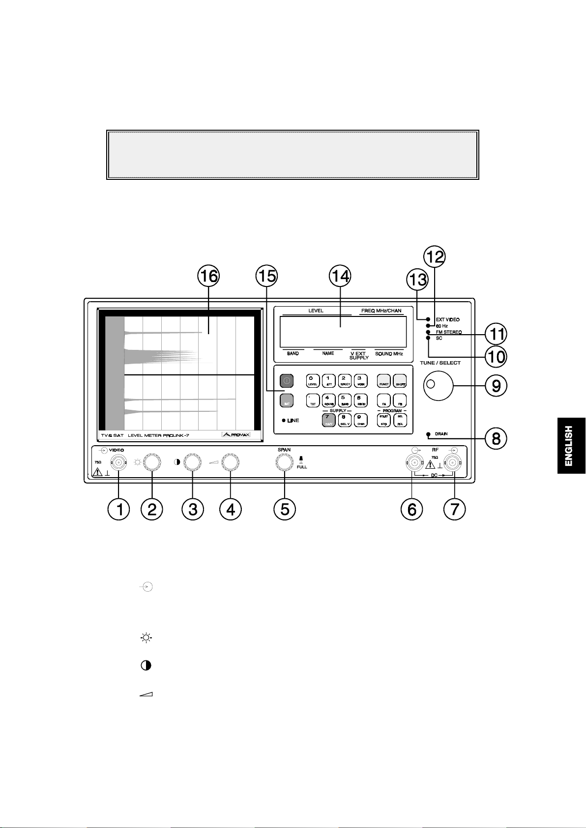
4.1 Description of the controls and elements
Front P a nel
Figure 1.-
[1]
[2]
[3]
[4]
[5]
06/97 PROLINK-7
VI D EO . Sta nda rd signal input of 1 V pp e xterna l video
3 Vpp maximum level. The signal is detected automatically and the monitor
switches for the screen display of the external video.
Control of the C R T brightness
Control of the C R T contrast
Control of the sound volume
SP AN . Am plitude of frequency swe ep control in spectrum mode.
When pulled out,
When pressed in,
FU LL S P AN
SPAN VARIABLE
Front panel.
, the sweep of the entire band is selected.
, it is possible by rotating it to vary the
Page 12

amplitude of sweep.
- 88 -
[6]
[7]
RF RF output to the interna l unit.
The LNB or antenna amplifier is supplied through this connector. BNC
connector with an output impedance of 75 Ω.
WARNING
When supplying the External Unit (LNB or antenna previous amplifiers) through
the I nterna l Unit (R e ceiver) , m ake sure tha t the cable connecte d to the RF
[6] connector corresponds to the Internal Unit, and that the RF [7]
connector is connected to the E xte rna l U nit. I f the I nterna l U nit is connecte d to
RF [7] and an External Unit voltage is selected, the PROLINK-7 and the
Internal Unit will be connected to the opposite power supplies, which may
dam age one of the two piece s of equipme nt.
RF . R F signal input.
Maximum level: 130 dBµV. BNC connector with an input im pedance of 75 Ω.
ATTENTION
Note the importa nce to protect the RF [7 ] input signal with an a cce ssory to
block 50 Vpp AC, used in CATV cables (needed to feed the amplifiers) and
remote mode.
[8]
[9]
[10]
[11]
[12]
[13]
[14]
DR AI N . E xterna l units powering light indicator
It lights when the
TUNE/SELECT. Rotary selector.
Used for continuous tuning control or to select the options associated to each
key.
SC . Sound ca rrier light indica tor
It indicates that a sound carrier at the selected frequency has been detected
in the tuned transmission.
FM S T E RE O . S te reo F M a udio light indicator
It indicates that a stereo FM transmission has been tuned.
60 H z. F rame freque ncy light indica tor
It indicates that a 60 Hz frame frequency has been selected.
EX T V ID E O. V ideo signal pre sence light indica tor
It lights up when an external video signal is present through either the
VIDEO [1] connector or through the EUROCONNECTOR [46].
Alphanume ric displa y
LCD of two lines of sixteen characters and back lighting. It indicates the level,
frequency/channel, band, name of the broadcasting station, external units
power supply voltage, the sound system, etc.
PROLINK-7
is powering the External Unit.
06/97 PROLINK-7
Page 13

- 89 -
[15]
[16]
Keyboard
19 keys for function selection and numerical data input.
SCREEN
Cathode ray tube of the monitor.
Keyboard
[20]
[21]
Figure 2.-
Each key is coded with the colour indicating the related type of operation:
Red
: On and off. Maximum priority.
Green
: Alphanumeric data entry. This switches the keyboard in such
a way that successive pressing of the keys is interpreted
according to the numerical value associated with each key.
Blue
: Momentary operation. This is only active while the key is held
down.
POWER
This turns on the instrument, and the user can select either manual or
automatic power-off.
BAT. Batte ry volta ge
This indicates the battery power on the display [14] in volts. Momentary
operation
Keyboard.
06/97 PROLINK-7
Page 14

- 90 -
[22]
[23]
LINE
Light indicator which indicates whether the instrument is connected to the
mains.
LEVEL / 0
This key allows the user to select any of the different modes of measurement.
They vary according to the standard, the band, and whether or not there is an
optional card (QPSK, QAM, OFDM).
In the terrestrial bands the following measurement modes may be selected:
Analogue channe ls:
LEVEL
VIDEO/AUDIO
CARRIER/NOISE
Digital cha nnels:
DIGITAL CARRIER
CARRIER/NOISE
BIT ERROR RATE
In the s atellite band the following measurement modes may be selected:
Analogue channe ls:
LEVEL
CARRIER/NOISE
Measurement of the video carrier level
Measurement of the video-to-audio carrier ratio
Video carrier-to-noise ratio
Measurement of the digital channel power
Digital channel carrier-to-noise ratio
Measurement of the bit error rate for QAM and
OFDM modulations (only OPT-107-72 and OPT107-73)
Measurement of the video carrier level
Carrier-to-noise ratio
[24]
[25]
Digital cha nnels:
DIGITAL CARRIER
CARRIER/NOISE
BIT ERROR RATE
When the user selects the
CARRIER
measurements is displayed on the screen.
Number 0 in SHIFT mode.
TXT / •
This selects the Teletext information. As the Teletext circuit is optional, this
function is activated only if the µP detects its presence.
Decimal point the SHIFT mode
ATT / 1
This selects the attenuation in the RF input, from 0 to 80 dB on terrestrial
bands, and from 0 to 70 dB on the satellite band, in intervals of 10 dB. There
is also an AUTO position that selects the most appropriate attenuation
according to the input signal level, in order to centre the value of reading in the
optimum scale.
Number 1 in SHIFT mode.
BIT ERROR RATE
or
Measurement of the digital channel power
Digital channel carrier-to-noise ratio
Measurement of the bit error rate for QPSK
modulations (only OPT-107-71)
VIDEO/AUDIO, CARRIER/NOISE, DIGITAL
modes, the information on these
[26]
06/97 PROLINK-7
SPECT / 2
This allows the user to switch to the TV operating mode from spectrum
operating mode and vice versa.
Number 2 in the SHIFT mode.
Page 15

- 91 -
[27]
MODE / 3
This key selects the operating m ode of the
different modes are available:
TV
: Monitor operating as a conventional
TV+LV
: Monitor operating as a conventional
TV+LV+SY
indicator
: Monitor operating as a conventional
indicator
on the upper part of the screen (the analogue bar).
and the
line synchronizing pulse
screen. The line synchronizing pulse appears with a lateral
displacement of the picture if a TV carrier is tuned, or if there
is an external video signal input through the VIDEO [1]
connector or the Euroconnector [40]. The analogue bar level
indicator shown on the screen has been calibrated and
corresponds to the value indicated in the display.
LV
: Indication of the
OFF
: Deactivates the monitor.
signal le v e l
Number 3 in the SHIFT mode
PROLINK-7
monitor. The following
tele vision se t.
tele vision se t
tele vision se t
, with a
, with a
level
level
displayed on the
on the screen (the analogue bar).
[28]
SOUND / 4
This selects the type of sound. The options available in each case depend on
the
band
and the
4.50
: Sound carrier 4.50 MHz above the picture carrier.
5.50
: Sound carrier 5.50 MHz above the picture carrier.
5.74
: Selects the second carrier in DUAL or STEREO transmissions, at
standard
selected.
5.74 MHz of the picture carrier.
5.80
: Sound carrier 5.80 MHz above the picture carrier.
6.00
: Sound carrier 6.00 MHz above the picture carrier.
6.50
: Sound carrier 6.50 MHz above the picture carrier.
6.65
: Sound carrier 6.65 MHz above the picture carrier.
7.02
: Sound carrier 7.02 MHz above the picture carrier.
NTUN
: Sound detection narrow filter: 110 kHz (satellite bands)
BTUN
: Sound detection broad filter: 240 kHz (terrestrial and satellite
bands).
AM
: AM demodulation.
FM
: FM demodulation.
LV
: Tone whose frequency varies with the input signal level.
NICA
: Nicam decoding
OFF
: Suppresses the audition of the sound carrier in the speaker and
headphones.
Number 4 in the SHIFT mode
06/97 PROLINK-7
Page 16

- 92 -
[29]
[30]
BAND / 5
Selects the band.
Although the tuning is continuous between 5 and 862 MHz and
between 920 and 2150 MHz, a band select is included which limits the
spectrum display to the commercial bands presently in use and to select a few
special cases, such as FM or IF.
SUB
: SUB-BAND. From 5 to 45 MHz
VLO
: VH F LOW. From 45 to 170 MHz
VHI
: VHF HIGH. From 170 to 450 MHz
UHF
: UHF. From 450 to 862 MHz
SAT
: S atellite T V. Fr om 920 to 2150 MHz
IF
: Intermediate frequency 38.9 MHz
FM
: FM. From 87 to 109 MH z
Number 5 in the SHIFT mode
SRCH / 6
This is the function for automatic station search. Starting at the present
frequency or channel, it searches until finds a station with an adequate level.
The threshold level can be defined by the
The search function halts the search process when the end of the band being
used is reached, if it is in frequency mode, or when any key is pressed. The
sound is deactivated during the search process. This function cannot be used
on FM and IF bands.
SEARCH LEVEL
function.
[31]
[32]
[33]
Number 6 in SHIFT mode.
mA/V / 7
This indicates on the display [14] the voltage and current being supplied to the
LNB or external amplifier.
Number 7 in the SHIFT mode.
SEL V / 8
This selects the voltage supplied to the external units (LNB or previous
amplifiers) from the
18 V and 24 V on terrestrial bands , and EX, 13 V, 15 V, 18 V, 13 V + 22 kHz,
15 V + 22 kHz and 18 V + 22 kHz on the satellite band. In the EX position no
voltage is supplied to the external unit, making it possible to supply it with an
external power source through the RF [6] connector.
Number 8 in the SHIFT mode.
CHAN / 9
This switches the display indication [14] from channel to frequency. In channel
mode the selection of the tuning frequency is adjusted to the selected channel
set (CCIR, OIRT, etc.). See the channel-frequency tables in the A appendix at
the end of this manual.
PROLINK-7
. The available voltages are: EX, 13 V, 15 V,
Number 9 in SHIFT mode.
06/97 PROLINK-7
Page 17

- 93 -
[34]
FUNCT
This selects the functions. When this key is pressed, a function menu with the
following fields appears on screen:
TV STANDARD
The user can select any of the various TV standards available, as a function
of the band:
B/G, D/K, I, L, M, N
band channels and
DIG
(digital channels) or
or
DIG
(digital channels) for the terrestrial
ANL
(analogue channels) for the
satellite band channels.
UN I T S : dBµV , dBm V, dBm, Lin
This selects the units of measurement in which the signal level is shown on the
display [14]. T he units may be linear (µV, mV, V) or logarithmic (dBµV, dBmV,
dBm).
CHANNEL SET
This selects one of the available channel tables.
ME AS U RE BW
This selects the bandwidth of the spectrum display filter between:
Terrestrial channels:
100 kHz, 230 kHz or 4 MHz
.
Satellite channels:
100 kHz, 230 kHz or 1 MHz
Note
: This filter is only effective in the variable SPAN mode. In the FULL SPAN
.
mode the filter is always:
4 MHz
: terrestrial band channels
1 MHz
: satellite band channels
NICAM CHANNEL
This selects the NICAM sound channel that is sent to the loudspeaker.
SAT VID EO POL
This selects the polarisation of the video carrier: positive or negative.
LNB LO C AL O S C
It defines the frequency of the local oscillator (L.O.) of the LNB used in the
receiving installation which is being studied. In the satellite band, this parameter
must be defined in order to be able to tune in the channel mode in accordance
with th e sat ellite channel-tables described in the A appendix at the end of this
manual.
CHANNEL BW
Selects the bandwidth of the digital channels. This parameter must be defined
in order to measure the power or the carrier-to-noise ratio on digital channels.
BEEP
Activates/deactivates the beeper.
AGC MODE
Activates/deactivates the automatic gain control.
06/97 PROLINK-7
Page 18

- 94 -
DATA LOGGER
It enables the acqui si t i on, s torage and pri nti ng of up to 9801 measurements (99
memories x 99 test points). The measurements may be taken in a fully
automatic way.
NEXT PAGE
It gives access to the next page in the function menu.
EXIT
Exit from the function menu.
CLOCK
Date and time setting.
ALARM
Selects a date and a time for automatic power on.
SEARCH LEVEL
Selects the threshold level of the automatic station search function: SEARCH
FRAME
This permits to choose the fram e frequency between 50 and 60 Hz.
[35]
[36]
[37]
[38]
[39]
PREVIOUS PAGE
It gives access to the previous page.
SHIFT
It enables the user to tune directly the desired frequency with the numerical
keyboard. When the second decimal figure is introduced, confirmation is
established. It also enables the cursor to be displaced within the menus that
appear on screen.
FA
Key for direct function assignment.
FB
Second key for direct function assignment.
START / STO
This key stores a configuration and takes measurements and/or makes printouts with the DATA LOGGER function.
SEL / R CL
This retrieves a measuring configuration and activates/deactivates
lines/columns in the DATA LOGGER function.
06/97 PROLINK-7
Page 19
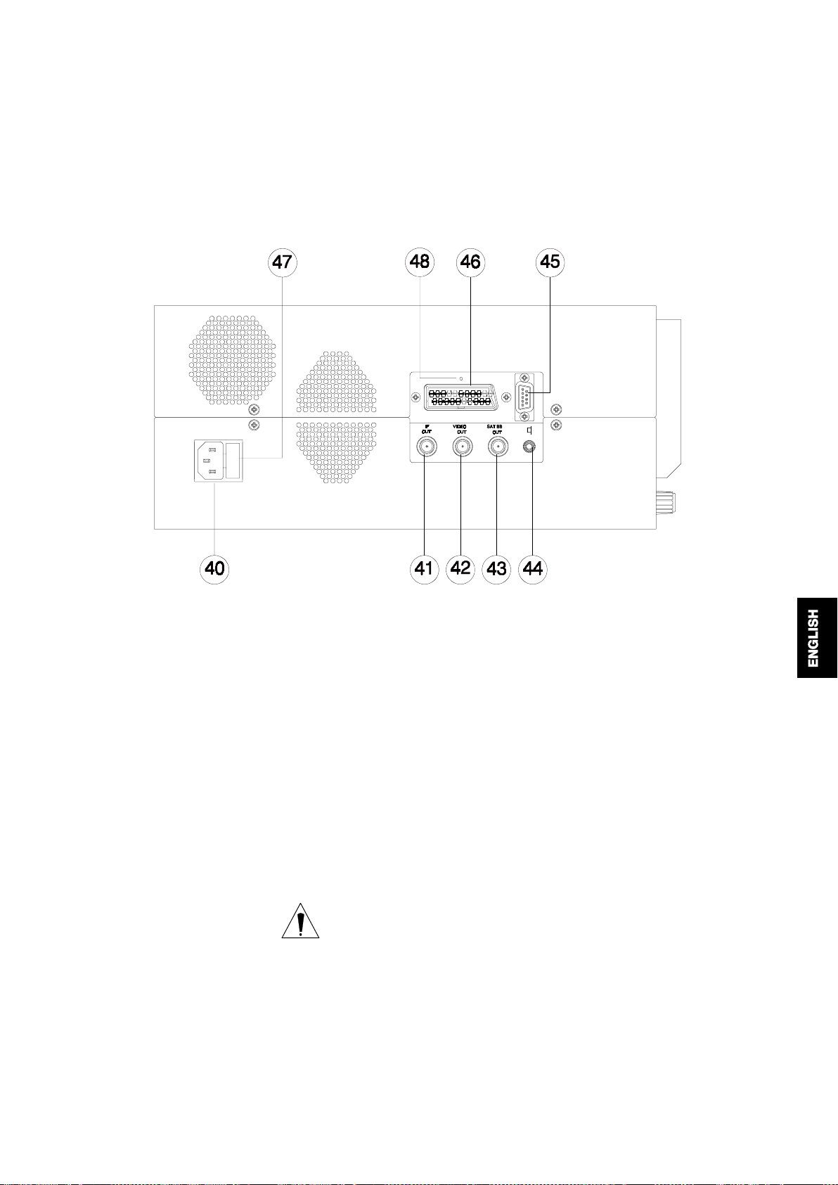
Side pane l
- 95 -
[40]
[41]
[42]
[43]
Figure 3.-
M ains input
Voltages from 95 to 250 V 50-60 Hz.
IF OUT. IF output at 38.9 MHz.
BNC connector with an output impedance of 75 Ω.
VI D EO O U T . C omposite video output
Amplitude of 1 Vpp and positive polarity. In the satellite band it is possible to
work with positive and negative video signals. The correct selection of this
function enables the user to view signals of either polarity. BNC connector with
an output impedance of 75 Ω.
WARNING
This signal should not be connected at circuit points with voltage, only to
standard video signal inputs with 75
instrument as a result of ignoring this precaution is not covere d in the w arranty.
S AT B B O U T . Ba s e ba nd sa te llite sig na l ou tput
The triangular modulation dispersal or Buergg is not removed. BNC connector
with an output impedance of 75 Ω.
Side panel.
Ω
impedance. Any damage to the
06/97 PROLINK-7
Page 20
- 96 -
[44]
[45]
[46]
[47]
[48]
Output jack for stere o sound
RS-232C connector
Enables the remote control of the
well as data dumping to a printer.
Euroconnector
Fuse holder
Support for the mains fuse.
RESET buttom
Enables the user to restart the instrument if there is any irregularity in its
functioning. If it is necessary to reset the instrument, press the reset button with
the instrument turned off.
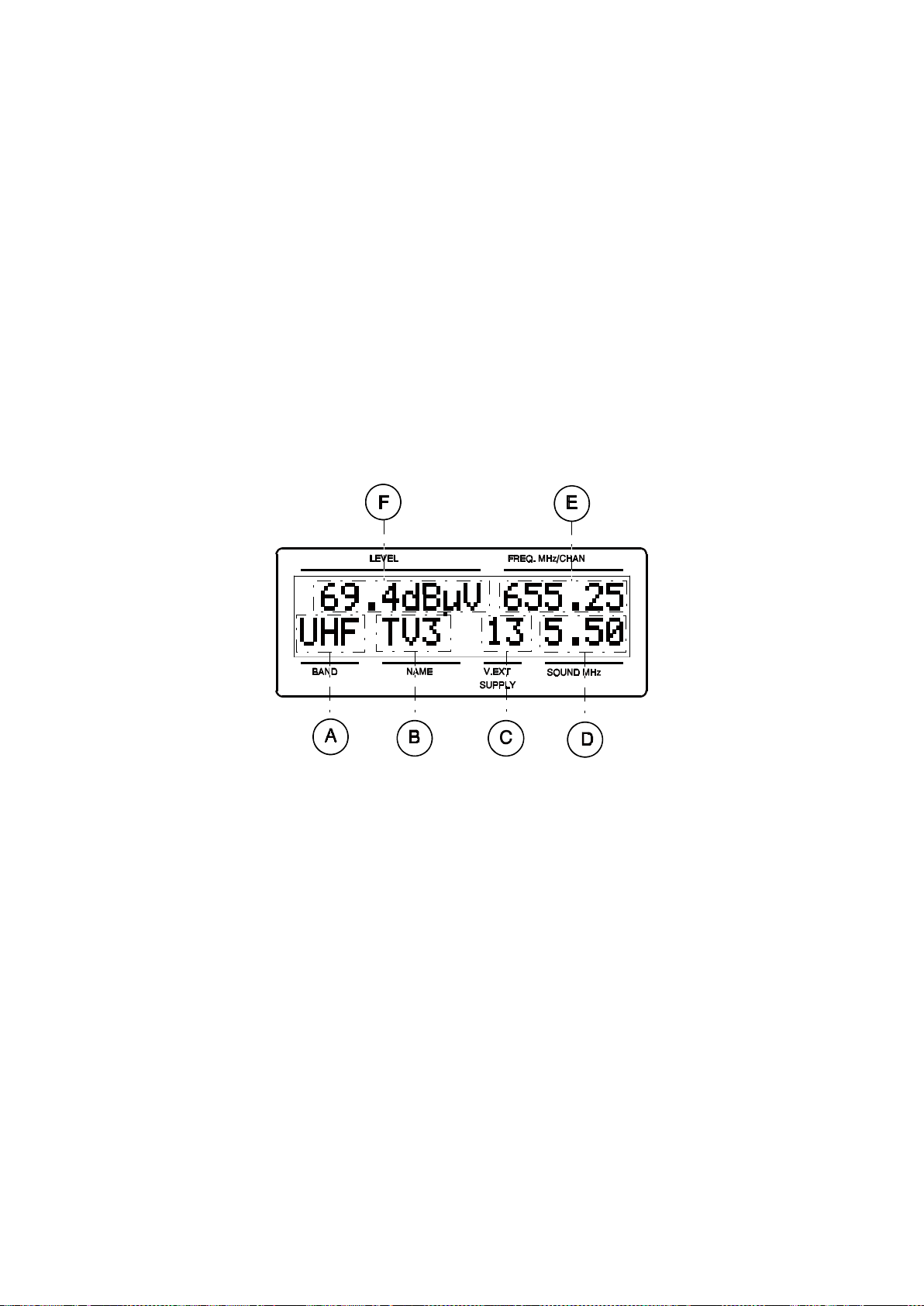
Display
PROLINK-7
from a personal computer, as
Figure 4.-
The alphanumeric display consists of two lines. The top line provides the
principal information.
[E] W orking frequency or channel.
[F] Input signal level.
The second line provides supplementary information.
[A] Present RF band.
[B] N am e assigned to the configuration memory. This information is only displayed
if there has been no change in the parameters of the selected configuration.
[C] LNB or external unit voltage supply.
[D] Type of sound or frequency of the selected carrier.
The numbers [17], [18] and [19] do not correspond to any part of the instrument
and have purposely been omitted from this list.
Possibly, other error m essages or indications for the user may appear on the
lower line.
06/97 PROLINK-7
Display.
Page 21
4.2 Using the PRO LIN K-7
4. 2. 1 Se lection of the R F band
- 97 -
Press the
BAND/5
[29] key. By turning the
TUNE/SELECT
[9] rotary selector,
the different RF bands will appear on the alphanumeri c display [14] in sequential order.
When the desired band appears, press the
BAND/5
[29] key again.
Although the tuning is continuous between 5 and 862 MHz and between 920
and 2150 MHz, a band selection is included which limits the spectrum display to the
commercial bands presently in use and to select some special cases, such as FM or
IF.
The following are the selectable bands:
Name Corresponding ba nd F reque ncy ( M H z)
SUB SUB-BAND 5-45
VLO VHF LOW 45 to 170
VHI VHF HIGH 170 to 450
UHF UHF 450 to 862
SAT SATELLITE TV 920 to 2150
IF Intermediate frequency 38.9
FM FM 87 to 109
Table 1.-
Frequency bands.
4.2.2 Automatic transmission search
By pressing the
SRCH/6
[30] key search starts at the present frequency or
channel until it finds a transmission with a level higher than the threshold level
previously established with the
The
SEARCH
function halts the search process when the end of the present
SEARCH LEVEL
function.
band is reached, if it is in frequency mode, or when a key is pressed. In channel mode,
the search process is halted when the last channel of the group selected is reached
(see Appendix A). The sound is deactivated during the search process.
This function cannot be used in the FM bands nor in the IF ones. In the satellite
band, the search process is only available in frequency mode.
06/97 PROLINK-7
Page 22

4.2.3 Frequency selection
- 98 -
When the
CHAN/9
[33] is pressed, tuning by frequenc y swit ches t o channel and
vice versa. Select tuning by frequency (the tuned frequency appears in the upper righthand corner of the alphanumeric display [14]. There are two methods for selecting the
frequency:
1.
Entering via TUNE SELECT [9] selector
With the
TUNE/SELECT
[9] rotary selec tor, sel ect the des ired fr equency (tuni ng
is continuous from 5 to 862 MHz and from 950 to 2150 MHz).
2.
Ente ring via keyboa rd
Press the
value of the desired frequency in MHz, with
figure acts as a confirmation). The
[35] key (the frequency indi cat ion di sappears). Then select the
SHIFT
two decima l figures
PROLINK-7
will wo rk out the synthesised
(the second
frequency closer to the value keyed and shows it on the alphanumeric display.
If the entered frequency corresponds to a different band from the programmed,
the band will be changed to the correct value for the new frequency.
4.2.4 Channel selection
With the
CHAN/9
[33] key, select the channel tuning mode (in the upper righthand corner of the alphanumeric display [14]). The name of the tuned channel will be
displayed. By means of the
TUNE/SELECT
[9] selector we select the desired channel.
4.2.5 Measuring mode selection
Using the
PROLINK-7
, the user can take different kinds of measurements,
depending on the standard, the band and the available options:
T erre stria l bands:
Analogue channe ls:
LEVEL
VIDEO/AUDIO
CARRIER/NOISE
Digital cha nnels:
DIGITAL CARRIER
CARRIER/NOISE
BIT ERROR RATE
Measurement of the video carrier level
Measurement of the video-to-audio carrier ratio
Video carrier-to-noise ratio
Measurement of the digital channel power
Digital channel carrier-to-noise ratio
Measurement of the bit error rate for QAM and
OFDM modulations (only OPT-107-72 and OPT-10773, respectively)
S a te llite ba n d:
Analogue channe ls:
LEVEL
CARRIER/NOISE
Digital cha nnels:
DIGITAL CARRIER
CARRIER/NOISE
BIT ERROR RATE
Measurement of the video carrier level
Carrier-to-noise ratio
Measurement of the digital channel power
Digital channel carrier-to-noise ratio
Measurement of the bit error rate for QPSK
modulations (only OPT-107-71)
06/97 PROLINK-7
Page 23
- 99 -
To select a particular measuring mode, press the
LEVEL/0
[23]. On the right
part of he display the mode in use will blink, and may be changed by means of the
TUNE/SELECT
[14], press the
When the
[9] selector. W hen the desired operating mode appears on the display
LEVEL/0
[23] key again.
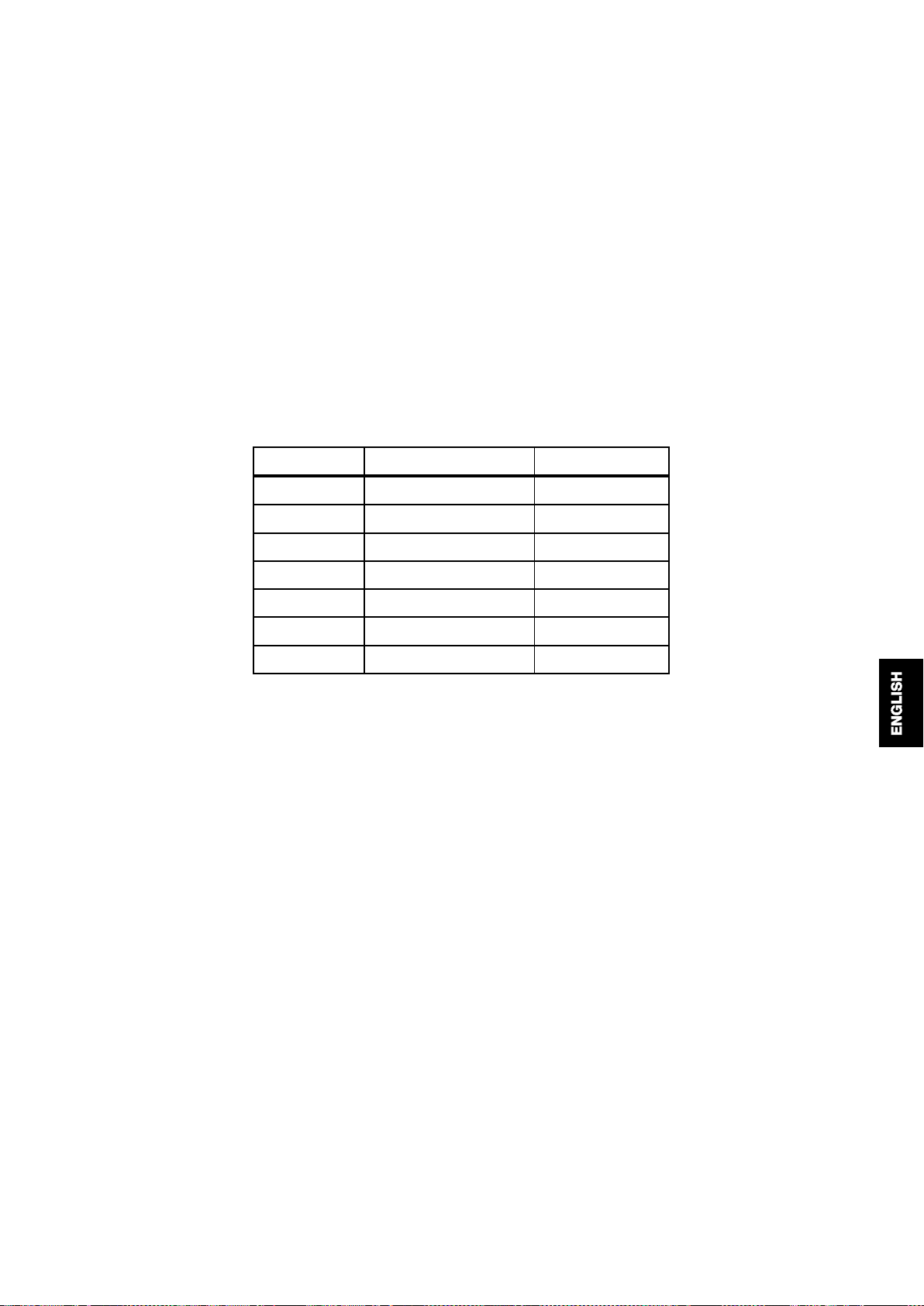
VIDEO/AUDIO
ratio measuring mode is selected the following
information appears on the [16] monitor:
Figure 5
.- Video/Audio ratio m easuring mode
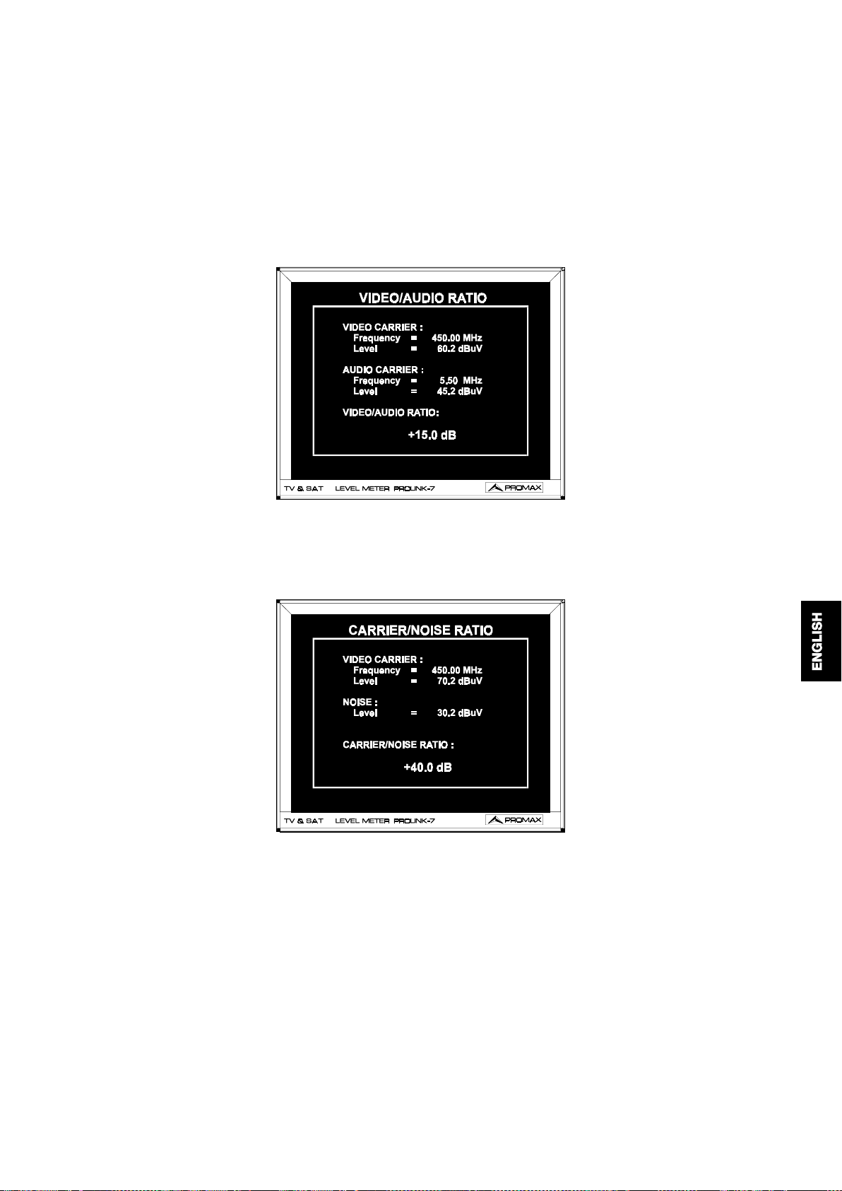
When the
CARRIER/NOISE RATIO
measuring mode is selected the following
information appears on the [16] monitor:
Figure 6
.- Carrier/Noise ratio measuring mode
The user should be aware that the measurement will take severa l seconds to
stabilize (six seconds at the most). Each time the unit ends a measurement, an
asterisk will appear at the right side of the measurement (when a dot appears, it means
the unit is processing the measurement).
When measuring channels in the satellite band or digital channels, to measure
the C/N ratio correctly, the bandwidth of the channel must be defined previously, using
the
CHANNEL BW
function on the functions menu. The
PROLINK-7
takes the carrier
measurement in the centre of the channel (the frequency tuned) and the noise
measurement at the frequency tuned plus half the bandwidth of the channel, and
applies the necessary bandwidth and signal detector corrections automatically.
06/97 PROLINK-7
Page 24

- 100 -
When the
DIGITAL CARRIER
measuring mode is selected the following
information appears on the [16] monitor :
Figure 7.-
4.2.6 Selection of the TV mode
In addition to operating as a television set, the monitor of the
Power measuring mode for digital channels
PROLINK-7
can
act as an analogue level indicator, and can display the line synchronising pulse just as
it would appear on a screen of an oscilloscope.
Press the
MODE/3
[27] key. By turning the
TUNE/SELECT
[9] rotary selecto r,
the user can choose the function of the monitor. On the display [14] the different TV
modes will appear one after the other. Pressing the
MODE /3
[27] key again activates
the selected display mode.
Figure 8.-
Selection of the display mode.
06/97 PROLINK-7
Page 25

The basic modes available are:
- 101 -
: Monitor operating as a conventional
TV
: Monitor operating as a conventional
TV+LV
on the upper part of the screen (the analogue bar).
and the
line synchronizing pulse
TV+LV+SY
indicator
: Monitor operating as a conventional
indicator
tele vision se t
tele vision se t
tele vision se t
.
, with a
, with a
level
level
displayed on the
screen.
: Indication of the
LV
: Deactivates the monitor.
OFF
4.2.6.1 Operation in SYNC mode
signal le v e l
on the screen (the analogue bar).
This function permits to display the line synchronising pulse corresponding to
a tuned signal on the monitor.
To select the SYNC (synchronising) function, press the
turning the
TUNE/SELECT
[9] rotary selec tor t he di ff erent di spl ayi ng modes will appear
on screen (choose the TV + LV + SY mode). Press the
MODE/3
MODE/3
[27] key again.
[27]. By
The monitor is divided into three sections. In the top section an analogue bar
appears which indicates the level of the signal received. On the lower left-hand side
the line synchronising pulse is represented as it would appear on the screen of an
oscillosc ope. On the lower right-hand side the TV picture is shown, shifted to the right,
Line synchronism + level bar + TV
The
SYNC
Figure 9.-
function shows on the monitor the line synchronising pulse; starting
from this signal it is possible to perform a qualitative analysis of the TV picture
delivered to the end user.
06/97 PROLINK-7
Page 26

- 102 -
The study of the line synchronism pulse facilitates the detection of possible
problems like: saturation of signal, lack of chroma in the amplitude of the burst or
possible double-image produced by indirect beams captation (as it is shown in
figure 10).
Figure 10.-
4.2.6.2 Operation as a spectrum analyzer
To select the Spectrum Analyser function press the
Line synchronism
SPECT/2
[26] key with the
monito r activate d. The m onitor w ill display the spectrum mode screen as it is shown
in figure 11.
The spectrum analyser function allow s the user to discover the signals present
in each band he is working in quickly and easily.
The frequency spectrum analysis may be conducted in the entire band
selected in
variable SPAN
FU LL SP AN
mode.
mode or in the proximity of the present tuning frequency in
In variable SPAN mode it is possible to choose the display spectrum filter by
using the
MEASURE BW
option of the function menu. It is possible to select the
display spectrum filter bandwidth between:
Terrestrial bands: 110 kHz, 230 KHz or 1 MHz
Satellite band: 110 kHz, 230 KHz or 4 MHz
In
FU LL SP AN
mode this filter is always 1 MHz for the terrestrial bands and
4 MHz for the satellite band.
In the spectrum analyser mode, a vertical base bar appears on the left-hand
side of the monitor screen and the lobes representing the signals are shown
horizontally, with the higher frequencies in the upper section of the screen and the
lower frequencies in the lower sect ion. The distance with respect to the base bar or the
amplitude of the lobe represents its power and is proportional to the level that would
be measured with the level meter tuning every frequency.
06/97 PROLINK-7
Page 27

- 103 -
Figure 11.-
Spectrum analyzer.
When the Spectrum Analyser mode is selected, the display eliminates the level
indication t o display a reference value (REF. LV) which corresponds to a marker on the
screen. This reference level is 70 dBµV by default, and it can be modified using the
[25] key. The subdivisions that appear on the screen represents 10 dB each. In
ATT/1
the spectrum analyser mode the presentation of the tuning frequency remains
deactivated on the display [14].
Select the
FULL S PAN
mode by pulling out the
[5] control; the frequency
SPAN
spectrum analysis is executed in the entire band selected. A black horizontal line or
marker representing the tuning frequency appears on the screen. As the user moves
the
TUNE/SELECT
control [9], the marker will move through the entire spectrum,
allowing an approximate pre-tuning of the frequency corresponding to the lobe that
coincides with the marker.
Select the variable
SPAN
function by leaving the
SPAN
[5] potentiometer in he
rest position (pressed in). The frequency spectrum analysis is conducted in the
proximity of the tuning frequency, that can come to zero SPAN. In that case, the entire
screen coincides with the same tuning frequency.
By choosing a specific SPAN and varying the tuning with the
TUNE/SELECT
[9] control, the user can slowly sweep the entire selected band of frequencies.
When the
SPECT/2
[26] key is pressed, the
PROLINK-7
backs to its normal
operation, the monitor displays the tuned frequency and the display indicates the value
of the frequency or channel at the position of the cursor and the level measured at that
point.
One of the applications of the
PROLINK-7
operating as spectrum analyser is
in the search for the best orientation and position of the receiving antenna. This is
particularly important i n UHF. Because such frequencies are involv ed, wit h wavelengths
ranging from 35 cm to 65 cm, if the antenna is shifted only a few centimetres, the
relationship between the picture, chrominance and sound carrier frequencies change,
affecting the quality of the picture in the receiver.
If there is an excess of sound carrier, tearing or 'moiré' may appear on the
screen due to the frequency beats between the sound, chrominance and the picture
frequencies.
06/97 PROLINK-7
Page 28

- 104 -
If there is a chrominance carri er def ect , then t he tel evision colour amplifier must
function at maximum gain, which could result in noise appearing all over the television
screen with points of colour that disappear when the saturation control is reduced; in
an extreme case, loss of colour m ay occur.
4. 2. 7 Configuration me mory
To facilitate measurement, the
PROLINK-7
is able to store up to 99
configurations in an internal memory. In this way, it is possible to select the most
common transmissions in a work area with their corresponding configurations quickly
and easily.
If the battery is changed, the stored configurations are saved for an indefinite
period. If not, the present configuration of the instrument is saved only as long as the
battery remains connected.
The following parameters are stored in each configuration: the name assigned
to the memory, band, frequency or channel number, the measurement units of the
level, TV standard, supply voltage (VLNB), sound and type of measurement.
The different measuring configurations can be retrieved with the DATA
LOGGER function, in order to conduct different data acquisitions in a completely
automatic way and store them in the memory for later print-out or processing.
4. 2. 7 .1 Storing a configuration (ME M O R Y S T O R E)
To store a particular configuration, follow this procedure:
1. Input the parameters of the desired configuration in the
PROLINK-7
(frequency/channel, band, etc.).
2. Press the
START/STO
on the monitor. With the
[38] key. The
TUNE/SELECT
MEMORY STORE
screen will appear
[9] selector or using the numeric
keyboard, select the memory number in which the configuration will be
stored. During the process of adjusting the instrument, a single initial
configuration is stored in all the memories by default.
If a configuration is stored in a memory location already containing
inform ation, t hat da ta will be lost.
06/97 PROLINK-7
Page 29

- 105 -
3. Assign a name (label) to the memory location (optional). Press the
[35] key. By turning the
TUNE/SELECT
[9] selector the different characters
will appear cyclically in the first position of the configuration name. Once the
first character is selected, press the
[35] key again and choose the
SHIFT
second character. Repeat this process up to a maximum of 4 characters.
Once all the necessary characters have been selected, the user must press
the
START/STO
key [38] to accept the name.
Figure 12.- MEMORY STORE
screen
SHIFT
4. Finally, press
START/STO
[38] and the configuration will be st ored. If a ny
other k ey is pr essed, an er ror w ill be indic ated and the m emory will not be
updated.
4. 2. 7 .2 R etrieving a configuration (ME M O R Y R E C ALL)
Press the
SEL/R CL
[39] key. The screen
MEMORY RECALL
will appear on the
monitor which shows the different parameters of each measuring configuration stored.
With the
TUNE/SELECT
to be retrieved (a number between 1 and 99). Pressing the
[9] selector or the numeric keyboard, select the configuration
SEL/R CL
[39] key again
will retr ieve the config uratio n.
Figure 13.- MEMORY RECALL
06/97 PROLINK-7
Screen
Page 30

4.2.8 Selecting the attenuators
- 106 -
Press the
By turning the
TUNE/SELECT
[25] key. The selected attenuation will appear on the display.
ATT/1
[9] rotary encoder, the user can select the attenuation
in the RF [7] input, from 0 to 80 dB in TV, or from 0 to 70 dB in SAT, in intervals of
10 dB. Press the
[25] key again to activate the selected attenuation.
ATT/1
There is an AUTO position which selects the most appropriate attenuation as
a function of the input signal level, in order to centre the value of the reading in the
optimum scale.
If the spectrum analyser mode (SPECTRUM) is selected, this key affects the
reference level (see section 4.2.6.2).
WARNING
The use of the attenuator automatic selection mode, is limited by the signal
maximum level applied at the input of the equipment. If a sudden signal level
variation is produced at the RF input, and it is beyond the total signal levels of:
TV: 95 dBµV
SAT: 105 dBµV
(typical values) the tune circuit may become out of control (PLL synthesized)
giving as a result wrong level readings.
If this situation occurs, disconnect the input signa l a nd se lect a n a ttenua tion of
60 dB or higher.
Similar effects can be observed when at the RF input appears an important
number of carriers with a high level. To be able to determinate the equivalent
level of a carrier group (w ith similar levels) at the RF input, it is possible to use
the expression:
Lt=L + 10 log N
Lt: total level
L: average level of the carrier group
N: number of carriers
So, if there are ten carriers wit h a l evel near to 85 dBµV, its equivalent level will
be:
85 dBµV + 10 log 10 = 95 dBµV
Observe that in this case if automatic attenuation mode is selected, loss of
tuning by overload of the RF input may occur besides other effects such as
tuner saturation and generation of intermodulation products that will mask the
spectrum visualization.
The global result of this effects is, in the automatic attenuation mode, the
difficulty to find the correct measurement scale or the presentation of incorrect
measurements.
06/97 PROLINK-7
Page 31

4. 2. 9 Se lection of the sound mode
- 107 -
Press the
SOUND/4
alphanumeric display [14]. By turning the
can chose the type of sound. Pressing the
[28] key. The selected sound mode will blink on the
TUNE/SELECT
SOUND/4
[9] rotary selecto r, the user
[28] key again activates the
selected sound type. The table 2 shows the possible values of the sound mode.
Type Function Band
4.50 Sound carrier 4.5 MHz above the picture carrier Terrestrial
5.50 Sound carrier 5.5 MHz above the picture carrier Terrestrial
5.74 Selects the second carrier in DUAL or STEREO transmissions, at 5.74 MH z of
the picture carrier
5.80 Sound carrier 5.8 MHz above the picture carrier SAT
6.00 Sound carrier 6.0 MHz above the picture carrier Terrestrial
6.50 Sound carrier 6.5 MHz above the picture carrier Terrestrial
6.65 Sound carrier 6.65 MHz above the picture carrier SAT
7.02 Sound carrier 7.02 MHz above the picture carrier SAT
NTUN Narrow sound detection filter, 110 kHz Satellite
BTUN B road sound detection filter, 240 kHz Terrestrial
Terrestrial
SAT
Satellite
NICA* NICAM decoding Terrestrial
AM AM demodulation FM/TER
FM FM demodulation FM/TER
LV Tone whose frequency varies with the signal level All
OFF Suppresses the sound All
Table 2.-
When the LV function is selected, the speaker of the
Sound modes
PROLINK-7
emits a tone
whose frequency depends on the level of the signal received. This is very useful when
installing antennas, since the user can locate the peak signal without having to look
continually at the display of the field meter, and therefore he can devote his full
attention to the orientation process.
Selecting the AM and FM options enables the user to hear signals resulting
from AM or FM modulation.
06/97 PROLINK-7
Page 32

- 108 -
When the
NICAM
option is selected on the display, information about the
NICAM type and the error rate will be sho wn in th is form at:
'N' + error + type
error = quality indication of the error rate:
"<": error rate < 1e-5
"5": 1e-5 < error rate < 1e-4
"4": 1e-4 < error rate < 1e-3
"3": 1e-3 < error rate < 2.7 e-3
">": error rate > 2.7 e-3
type = NIC AM type:
"--": no NICAM is detected
"du": dual NICAM
"st": stereo NICAM
"mo" mono NICAM
Therefore, for example, from the indication in figure 14 it has to be interpreted
that NICAM sound is selected, the error rate is between 1 e-5 and 1 e-4 and the
NICAM detected is dual.
Figure 14.-
4. 2. 1 0 E xterna l units power supply
The
PROLINK-7
can supply the voltage needed to power the external units
NICAM sound
(antenna preamplifiers, in the case of terrestrial TV, or LNB, in the case of satellite TV).
The
PROLINK-7
has two different operating modes, depending on whether or
not it supplies the external units.
RF input
From DC to 100 Hz 50 V rms (powered by the mains supply)
30 V rms (not powe red by the ma ins supply)
From 5 to 2150 MHz 130 dBµV
06/97 PROLINK-7
Page 33

- 109 -
4. 2. 1 0. 1 E X powe r supply
In this operati ng mode the power supply of antenna preampli fiers (terrestri al TV)
or the s atellite T V rec eiver ( dome stic or co mmu nity) supplies the external unit.
The
PROLINK-7
is connected in series in the line that links the external unit
and the satellite TV (do mestic) or SMATV
In this configuration, the EX supply mode of the external units to the
PROLINK-7
TUNE/SELECT
display [14]. Pressing again the
has to be used. For this, press the
[9] rotary selector until the EX mode appears on the alphanumeric
SEL V/8
mode.
heading
(community), as shown in figure 15.
SEL V/8
[32] key. Turn the
[32] key again activates the external supply
Figure 15.-
WARNING
W hen supplying the e xternal unit through the interna l unit, make sure tha t the
cable connected to the R F [6] connector corresponds to the interna l unit,
and that the RF [7] connector is connected to the external unit. If the
internal unit is connected to RF [7 ] a nd an exte rna l unit voltage is sele cte d,
the P R O LIN K -7 a nd th e in te rna l unit w ill be connecte d to the opposite powe r
supplies, which ma y dama ge one of the two pieces of e quipment.
06/97 PROLINK-7
EXT power supply of the external unit.
Page 34

4. 2. 1 0. 2 I nterna l power supply
- 110 -
The
PROLINK-7
can supply the voltage needed to power the External Unit. In
this case, the user can select several power voltages from the panel, depending on
wheth er it is a terres trial or Sate llite band. The maximum load is 5 W, in continuous
loading.
Type of T ele vision Power voltages
SATELLITE EXT, 13 V, 15 V, 18 V *
TERRESTRIAL EX T, 13 V, 15 V, 18 V, 24 V
Table 3.-
Power voltages to the external unit.
* The supply voltages in Satellite allow to superpose a square signal of 22 kHz with
the object to realise switching functions.
This signal becomes active whe n you
sele ct the wa nted unde rlined voltage pola riza tion.
Figure 16.-
External unit power supplying by the
PROLINK-7
.
It is possible to supply the double band LNB's and the polarity switching LNB's
by changing the power voltage.
The
DRAIN
[8] indicator li ght s when current is f l owing to t he ext ernal unit . I f any
kind of problem occurs (e.g., a short circuit), an error message appears on the display
[14] and the instrument ceases to supply pow er. The
PROLINK-7
does not return to
its normal operating state until the problem has been solved.
When the
mA/V/7
[31] key is held down, the lower line of the display [14]
indicates the real voltage and current being supplied to the external unit. This
measurement is taken even when an external supply has been selected.
Figure 17.-
06/97 PROLINK-7
Page 35

- 111 -
WARNING
When the external unit is powered with one of these voltages, particulary 18 V
or 24 V, it is not advisable for the instrument to function for more than thre e
minutes non-stop. S ince the total consumption is very high, the duration of the
battery charge is shortened considerably. It is advisable to disconnect the
instrument when it is not taking mea sureme nts.
4.2.10.3 Selecting the voltage supplied to the external unit
Press the
SEL V/8
voltage supplied to the LNB or external unit. Press the
[32] key and use the
TUNE/SELECT
SEL V/8
[9] dial to select the
[32] key again to
activate the selected voltage.
4.2.11 Teletext
When the
[24] key is pressed, Teletext information appears on the
TXT/·
monitor if a transmitter with this information is tuned. The first page to appear on the
screen is always page 100. If Teletext data is received, a counter located on the upper
edge of the screen indicates the page that is being processed. Using the
SELECT
[9] selector the user can choose the page of Teletext to be displayed.
TUNE/
If the page requested is not included in the Teletext service of the transmitter,
the sea rch will continue indefinitely. In such a situation the user can halt the search
process, either by exi t i ng t he Telet ext func ti on t hrough the
a new page number with the [9]
TUNE/SELECT
rotary selector.
[24] key or by entering
TXT/·
The Teletext function is especially valuable for the final optim ization process in
TV installations. Any interference or reception through indirect beams generates digital
in the digital information of the Teletext, which are highly visible as erroneous
characters on the screen.
4. 2. 1 2 S e lection of advance d functions
The
FUNCT
[34] key gives access t o the adv anced function menu, as selection
of TV standard, changing the units of measurement, channels table, bandwidth of the
measuring filter, etc.
When the FUNCT [34] key is pressed the following menu appears on the
monitor.
06/97 PROLINK-7
Page 36

- 112 -
Function menu, first page.
[9] selector it is possible to mo ve th e cu r so r within
Through the
Figure 18.-
TUNE/SELECT
the different fields. To select a function, place the cursor on it and then press the
FUNCT
[34] key.
The
NEXT PAGE
field gives access to the second page of the function menu.
Figure 19.-
Function menu, second page.
To exit the function menu, place the cursor on the
TUNE/SELECT
06/97 PROLINK-7
[9] rotary encoder. Then press the
FUNCT
[34] key.
field by using the
EXIT
Page 37

- 113 -
4.2.12.1 Selection of the TV standard
This function allows the user to change the television standard. Different
standards are available, depending on the band selected (terrestrial or satellite
channels). To change the standard, press the
TUNE/SELECT
the
FUNCT
T erre stria l bands
B/G , D /K, I, L, M , N
S a te llite ba n d
ANL
[9] to position the cursor in the
key [34]. A pull-down menu will appear with the following options:
,
(digital channels), as shown in Figure 20.
DIG
(analogue channels),
(digital channels), as shown in Figure 21.
DIG
FUNCT
key [34]. Turn the rotary selector
TV STANDARD
field and then press
Figure 20.-
Figure 21.-
By turning the
Selection of the standard, terrestrial channels.
Selection of the standard, satellite channels.
TUNE/SELECT
desired standard. Press the
FUNCT
[9] rotary selector, the user can select the
[34] key again to confirm the standard.
06/97 PROLINK-7
Page 38

The following table shows the features of the analogue terrestrial channel
standards.
- 114 -
System Lines/
Table 4.-
frame
B 625/50 7 MH z 5.5 MHz Neg FM
D 625/50 8 MHz 6.5 MHz Neg FM
G 625/50 8 MHz 5.5 MHz Neg FM
H 625/50 8 MHz 5.5 MHz Neg FM
I 625/50 8 MH z 6.0 MHz Neg FM
K 625/50 8 MH z 6.5 MHz Neg FM
L 625/50 8 MHz 6.5 MHz Pos AM
M 525/60 6 MH z 4.5 MHz Neg FM
N 625/50 6 MHz 4.5 MHz Neg FM
Selectable terrestrial analogue standards and their characteristics.
Channel
Bandwidth
Video/sound
separation
Video
mode
Audio
mode
If a digital channel is selected, whether terrestrial or satellite, for the
measurement of the level and the carrier-to-noise ratio to be correct, the bandwidth of
the channel must be defined, using the
CHANNEL BW
function of the functions menu.
4.2.12.2 Selection of units of measurement (UNITS)
Press the
cursor on the
FUNCT
[34] key and the units of measure menu will appear. The user can select the
FUNCT
UNITS
[34] key. The function menu will appear on screen. Place the
field by turning the
TUNE/SELECT
[9] rotary selector. Press the
units of measure, either dBµV, dBm, dBmV or linear units (µV, mV or V). Finally press
the
FUNCT
[34] key again to select the desired option.
Figure 22.-
Selection of units of measurement.
06/97 PROLINK-7
Page 39

- 115 -
4.2.12.3 Selection of the channel set (CHANNEL SET)
Stored in standard form, the
PROLINK-7
has twelve sets of channels (four for
terrestrial television and eight for satellite television ) so that the u nit can be adapted
to the needs of each c ountry or selection area. See the channel-frequency tables in the
A appendix at the end of this m anual.
Press the
FUNCT
on screen. By turning the
CHANNEL SET
function. By pressing the
[34] key to s el ect a channel s et. A f unct i ons menu will appear
TUNE/SELECT
[9] rotary encoder, place the cursor on the
FUNCT
[34] key, the menu of the available
channel set will appear.
By using the
set and finally press the
4. 2. 1 2. 4 S e lection of the me asuring bandw idth in spectrum mode (M E AS U RE BW )
TUNE/SELECT
FUNCT
With the spectrum analyser function in
[9] rotary encoder, place the cursor on the desi r ed
[34] key again to select the set.
SPAN VARIABLE
mode, it is possible
to choose the bandwidth of the measuring filter betw een 100 kHz, 230 kHz and 1 MHz
for the terrestrial bands and 4 MHz for the satellite band. For this, press the
[34] key. The functions menu will appear on screen. By turning the
rotary selector, place the cursor on the
FUNCT
TUNE/SELECT
[34] key the measuring bandwidth selection menu will appear. With the
[9] rotary encoder place the cursor on the desired bandwidth (100 kHz,
MEASURE BW
function. By pressing the
TUNE/SELECT
FUNCT
[9]
230 kHz or 1 MHz for terrestrial channels and 100 kHz, 230 kHz or 4 MHz for satellite
channels) and press the
FUNCT
[34] key to activate it.
For terrestrial television channels the default filter is the 230 kHz, while the
defau lt filter fo r satellite televisio n channels is 4 MHz.
: In the
Note
4.2.12.5 Selection of the NICAM channel (NICAM CHANNEL)
FU LL S P AN
1 MHz
4 MHz
function the measuring bandwidth is always
in the terrestrial bands
in the sa tellite band
With this function, the user can check NICAM sound modulations in stereo and
dual and select the sound channel emitted by the loudspeaker.
To do this, press the
By turning the
TUNE/SELECT
function. Press the
FUNCT
FUNCT
[34] key again. The channel emitted by the loudspeaker (A
[34] key. A functions menu will appear on screen.
[9] rotary encoder, place the cursor on the
NICAM
or B) is switched automatically.
4. 2. 1 2. 6 S e lection of the video polarity (S AT VI D EO P O L)
Press the
the
TUNE/SELECT
FUNCT
[34] key. The functi on menu will appear on sc reen. By turni ng
[9] rotary encoder, place the cursor on the
SAT VID EO POL
field.
On the right-hand side there will be the polarity presently selected (positive or
negative). To change the polarity, press the
FUNCT
[34] key.
This op tion co ncern s the re ceptio n on the SAT (satellite ) band.
06/97 PROLINK-7
Page 40

- 116 -
4 .2 . 1 2 . 7 F re q ue ncy of th e LN B lo ca l osc illa tor ( LNB LO C A L O S C )
This parameter must be defined in order to be able to tune in the satellite band
in channel mode in accordance with the channel tables described in the A appendix
at the end of this manual. To define it procedd as it follows: Press the
The functions menu will appear on screen. By turning the
selector, place the cursor on the
LNB LO C AL O S C
will be the frequency presently selected. If the
field. On the right-hand side there
FUNCT
TUNE/SELECT [
[34] key is pressed, that
FUNCT
[34] key.
9] rotary
frequency will be erase d and the user can assign a new frequency using the keyboard.
The frequency of the LNB local oscillator is expr essed in M Hz, with 5 fig ures
for the whole part, a decimal point and a decimal (which acts as confirmation). For
example, to select 9 GHz the number
9000,0
has to be entered.
This option concerns the reception of signals on satellite band.
4. 2. 1 2. 8 M e a suring bandwidth with digita l channels ( DI G IT AL C H BW )
The
PROLINK-7
permits the direct measurement of the power of the digital
channels, as well as the carrier-to-noise ratio. If these measurements are to be correct,
the bandwidth of the digital channel must be defined previously.
Press the
FUNCT
appear on screen. By turning the
on the
DIGITAL CH BW
[34] key to establish the bandwidth. A function menu will
TUNE/SELECT
field and press the
[9] rotary selector, place the cursor
FUNCT
[34] key. Use the keyboard to
enter the bandwidth in MHz of the digital channel (the activation is produced when
entering the decimal figure).
This option affects the measuring of digital channels.
4.2.12.9 BEEP
This function allows the user to switch the audible indicator ON and OFF. To
do this, first press the
FUNCT
position the cursor in the
key [34]. Turn the rota ry selector
field and press the
BEEP
FUNCT
TUNE/SELECT
[9] to
key [34]. The operating
state of the audible indicator signal w ill switch a utom atically.
4.2.12.10 Automatic gain control (AGC M ODE)
This function allows the user to activate (ON) and deactivate (OFF) the
automatic gain control. In this way the intermodulation of signals with a level greater
than 85 dBmV is reduced. It is not possible to display the input level measurement in
this functioning mode, since the gain of the tuner varies as a function of the input level.
The main purpose of this functioning m ode is to enable the user to improve the
picture quality in situations when the tuner is near saturation.
To switch the
selector
FUNCT
06/97 PROLINK-7
TUNE/SELECT
key [34]. The operating state of the AGC will sw itch a utoma tically.
on and off, press the
AGC
[9] to position the cursor i n the
FUNCT
AGC MODE
key [34]. Turn the rotary
field and press the
Page 41

4.2.12.11 DATA LOGGER
- 117 -
The
DATA LOGGER
function all ows the user to carry out, st ore and/or print out
up to 9801 measurements in a fully automatic way. It may be understood as a matrix
whose columns address the 99 memories of measuring configurations and lines permit
to store 99 measurements for every measuring configuration (conducted in different
points of the system or in th e same point on d ifferent times).
Before to proceed to take measurements by means of the DATA LOGGER
function it is necessary to store the measuring configuration/s in the memory by using
the
MEMORY STORE
Press the
menu will appear on screen. By turning the
the cursor on the
the
DATA LOGGER
function.
FUNCT
DATA LOGGER
[34] key to select the
screen will appear.
DATA LOGGER
TUNE/SELECT
field and press the
function. A function
[9] rotary encoder place
FUNCT
[34] key. Follow ing this,
Figure 23.-
DATA LOGGER screen
First of all, the user must indicate whether he wants to take measurements or
to print them, or to do both at the same time. For this, press the
SHIFT
key [35]
repeatedly (this is analogous to the tabulator in the Windows environment) until
positioned in the
MEASURE
field. Then turn the rotary selector
TUNE/SELECT
[9] to
activate (ON) or deactivate (OFF) the measurement function. The next step is to
activate or deact i vat e the measurement pri nt i ng f unc ti on. To do t hi s, use t he
[35] to position the cursor in the
with the rotary se lector
TUNE/SELECT
PRINT
field and activate it (ON) or deactivate it (OFF)
[9].
SHIFT
key
Secondly, select the des i red t i me interval i n whi ch t he measurements/print -out s
have to be done. For this, press the
to time (hh:mm) of the
INTE RVAL
SHIFT
field is activated. By turning the
rotary selector choose the hours. Then press the
[35] key several times until the part relat ive
[9]
SHIFT
TUNE/SELECT
[35] key again to access to
the minutes field and choose the desired number.
06/97 PROLINK-7
Page 42

- 118 -
The third operation is to activate the memory/ies or measurement
configuration/s (that is, the frequency, the standard, the mode, the units of
measurement, etc.) on which we want to take measurements. The heading of each
column describes the most important parameters of each memory (measurement
configuration), the name allocated to the memory location, the frequency, the units of
measurement and the measurement mode (LEV, C/N, V/A or BER if the corresponding
option is available). Use the
SHIFT
and then turn the rotary selector
(memory). Activate i t or deactivate it with the
key [35] to position the cursor in the columns field
TUNE/SELECT
[9] to position it in the desired colum n
SEL/R CL
[39] key. The activated columns
are brighter than those that are not activated.
Finally, the user must select the row/s where he wants to store the
measurements. For this, use the
SHIFT
row and activate it by pressing the
key [35] to position the cursor on the desired
SEL/R CL
[39] key.
To tak e the m easur emen ts, thr ee pos sibilities e xist:
a) Position the cursor on a column.
Te mpora l acquisition.
The measurements are taken on this memory (column) in all the rows that
are activated. If no row has been selected, the error message 'NO ITEM
SELEC TED ' will appear on the display.
b) Position the cursor on a row.
at the same time.
Acquisition of different types of measurements
The measurements are taken on this row in all the activated columns. If no
column has been selected, the error m essage 'NO ITEM SELECTED' will
appear on the display.
c) Place the cursor in the corner.
M ultip le a cquis itions .
The measurements are taken for all the rows and all the columns activated.
If no item has been selected, the error message 'NO ITEM SELECTED' will
appear on the display.
Once the user has defined all the parameters of the DATA LOGGER function
and selected the measurements he wants to take, there are two methods of execution:
immediate and scheduled.
Immediate execution
If the user wants to take the measurements (and/ or print them) immediately, he
must press the
START/STO
key [38] to proceed to m easurement and storage. During
the execution of the measurement, two arrows will appear in the upper left-hand corner
of the array (the 'x' and 'y' coordinates direct the m easurement/printing in progress).
To abort the DATA LOGGER operation, press the
LOGGER function, press the
FUNCT
key [34].
FUNCT
key [34]. To exit the DATA
06/97 PROLINK-7
Page 43

- 119 -
Sche duled e xe cution
If the user wants to schedule the instrument to take the measurements (and/or
print th em) at a pa rt icu la r t im e, he w ill h av e to schedule the alarm (see point 4.2.12.13
Alarm ). At the time set in the alar m, the instrum ent will pow er on (if it is off ), or will
automatically switch to the DATA LOGGER mode (if it is on) in order to take or print
the measurements. If the DATA LOGGER has been programmed to take more than
one measurement in the time domain and if the logging interval is longer than four
minutes, each time a measurement is logged, the instrument will reschedule the alarm
for the next measurement and it will power on th ree m inutes ( t
) before the time
warm-up
defined in the Interval field, in order to ensure maximum accuracy. If the DATA
LOGGER function is accessed while it is active, two blinking arrows (>>) will appear
in the upper left-hand corner of the array. To exit the DATA LOGGER screen, the user
must press the
FUNCT
key [34]. If any other key is pressed, the DAT LOGGER
functio n will abort.
This function has m ultiple applications, as equalizating channels in every outlet
or measuring signal attenuation in every outlet.
Measuring the fluctuations in the signal level in one particular outlet (temporal
acquisition)
.
Define the interval between acquisitions ( 1h, for example) and activate such a
number of lines that enables to carry out a study during 24 h (24 lines in the
example). The obtained report will permit to guarantee a correct working of the
system.
Equa lisation of channels in a pa rticular outlet (freque ntial a cquisition)
For this application a noise generator m ust be used. Activate several memories,
each one with different measuri ng fr equenci es. For example, t o t est t he VHF band,
for every one of the measuring modes (level, video/ audio, video / carrier), carry
out a frequency sweeping from 45 to 450 MHz every 50 MHz.
4.2.12.12 Clock (CLOCK)
An internal clock permits to record date and hour of data acquisitions.
Access to the second page of the function menu to change the hour and select
the
CLOCK
key. The present data and hour will appear on the display. Press the
the HOURS field will blink. Turn the
Press the
menu using the
SHIFT
[35] key again to access to the remaining hours fields (MINUTES and
TUNE/SELECT
TUNE/SELECT
[9] rotary encoder and the
SHIFT
[9] rotary encoder to modify it.
FUNCT
key and
[34]
SECONDS) and set the value using the rotary encoder. Proceed in a similar way to
modify the date (DAY-MONTH-YEAR). Once the date and hour are correct, press the
FUNCT
[34] key to validate them.
06/97 PROLINK-7
Page 44

4.2.12.13 Alarm
- 120 -
The
PROLINK-7
allows the user to define the time and date of the automatic
power on and the data logging if the DATA LOGGER function has been activated. The
alarm can be scheduled for a maximum of one year in advance.
Access to the second page of the function m enu to activate or deactivate the
alarm and select the
and the
FUNCT
[34] key. The display indicates whether the alarm is activated (ON) or
ALARM
menu by turning the
TUNE/SELECT
[9] rotary selecto r
not (OFF) as well as the date (DAY-MONTH) and time (HOUR-MINUTES-SECONDS )
selected. Press the
TUNE/SELECT
[9] rotary selector to change it. In order to modify the date and/or the
hour, press the
TUNE/SELECT
[9] rotary encoder until obtain the desired value. Once all the
SHIFT
SHIFT
parameters are correct, press the
4.2.12.14 Search level
[35] key and the ON-OFF field will blink. Turn the
[35] key until the field to modify blinks and turn the
FUNCT
[34] to validate them .
With this function it is possible to modify the threshold level of the station
automatic search. Access to the second page of the function menu to modify this level.
Place the cursor on the
SEARCH LEVEL
in use w ill be dis play ed . Pre ss t he
FUNCT
field. On the right side of the field the level
[34] and introduce a new level by using the
alphanumeric keyboard. When the second figure is introduced the confirmation is
produced automatically.
4.2.12.15 Frame
This function permits to modify the frame frequency. For this, access to the
second page of the function menu. At the right-hand side of the
FRAME
field appears
the frame frequency presently in use. If the user wishes to modify this frequency, place
the cursor on this field and press the
FUNCT
[34] key. Its value will change
automatically from 50 to 60 Hz or vice versa.
4.2.13 Direct access to functions
The
PROLINK-7
[36] and
FA
[37] keys give access to any of the functions of the
FB
. To establish the relation between the direct access key and a function,
access to the function menu, place the cursor on the desired function and press the
FA
[36] or
[37] key. From now on, when one the
FB
FA
or
keys is pressed, the
FB
access to this fu nction w ill be dir ect.
06/97 PROLINK-7
Page 45

- 121 -
4.2.14 Printing measurements or memories
By connecting the instrument to a printer it is possible to obtain a printed report
of a sequence of measurements just at the m oment they are taken, or later, if they are
recorded with the
DATA LOGGER
function. This enables the user to keep a file about
the state of the system and provide the documents related to the level measurements
for analysis purposes.
The installation process is reduced to connecting the printer, by means of the
connection cable provided, to the serial connector of the
PROLINK-7
. Before that,
switch off the pieces of equipment.
The serial connector is on the side-hand panel of the
PROLINK-7
, as it is
shown in the [45] connector in figure 3.
To print out the measurements press the
TUNE/SELECT
By pressing the
FUNCT
[9] rotary selector up to place the cursor on the
FUNCT
[34] key the
DATA LOGGER
screen will appear on screen.
[34] key, turn the
DATA LOGGER
field.
First, the printing field has to be activated. For this, press several times the
SHIFT
[35] key until place the cursor on the
PRINT
field. Use the
TUNE/SELECT
[9]
rotary encoder to activate it (ON).
Select the desired measuring configuration (columns) as it is explained in the
section
4.2.12.11 DATA LOGGER
measure if it has been established) only pressing the
necessary. When pressing the
and the lines (TEST POINT). To print out (and
START/STO
START/STO
[38] key, if the cursor is in the 'corner' ,all
[38] key is
the measurements of the intersection with activated lines and columns will be printe d
out. On the contrary, if only a measurement is required, when pressing the
START/STO
[38] key the cursor has to be on the corresponding line.
As example, the followi ng fi gure shows the outc ome of printi ng out t wo diff erent
measuring modes (<01> and <02>) with two lines activated (test points 1 and 2).
06/97 PROLINK-7
Page 46

- 122 -
LOCATION:
SIGNATURE:
DATE:
TIME:
TEST POINT: 1
<01> Ch -Meas.: LEVEL
Frequency:615.25 MHz
Level: 69 dBuV
<02> Ch -Meas.: LEVEL
Frequency:621.25 MHz
Level: 75 dBuV
DATE:
TIME:
TEST POINT: 2
<01> Ch -Meas.: LEVEL
Frequency:615.25 MHz
Level: 70 dBuV
<02> Ch -Meas.: LEVEL
Frequency:621.25 MHz
Level: 74 dBuV
Figure 24.-
4.2.14.1 Handshake and control lines
Next is described the handshake and control lines used by the
- The following parameters are used for printing through the serial port:
Rate: 19,200 bauds
D a ta b its: 8 bits
Parity: None
Stop bits: 1
To modify the printer parameters see 4.2.14.2 CI-23 set-up.
Printing measurements.
PROLINK-7
:
06/97 PROLINK-7
Page 47

- The control lines used are:
- DATA TRANSMIT (PROLINK-7 pin 3):
To send data to the printer.
- CLEAR TO SEND (PROLINK-7 pin 8) :
Data transfer control. Data are sent only when this line is active.
- DATA TERMINAL READY (PROLINK-7 pin 4)
This line is permanently active in order to indicate the establishment of
the communication.
Connections
- 123 -
The cable between the
connections:
PROLINK-7
Figure 25.- PROLINK-7
and the printer must have the following
RS-232C connector. Pins numbering.
06/97 PROLINK-7
Page 48

4.2.14.2 CI-23 Set-up
- 124 -
This point explains how to m odify the
printer keyboard:
POWER LED
[1]
SET-UP
[2]
FEED
[3]
ON
[4]
OFF
[5]
Figure 26.-
printer set-up. Figure 26 shows the
CI-23
CI-23 keyboard
To initiate the set-up mode push the
[1 ] PO WE R O N
[2] SET- UP
LED will flash u ntil set- up mode is turned off. The current param eter
and the
[4] ON
keys. The
status w ill be printe d. T he st atus of the DAT A BI TS p ara mete r will b e pr inted in ord er
to modify it if necessary.
To select the status of the resting parameters (PARITY, BAUD-RATE,
COUNTRY, PRINT M ODE, AUTO-OFF, EMULATION and DTR) push the
[3] FE ED
key. These parameters are selected in a sequential way. To modify the status of any
parameter push sequentially the
[2 ] SE T - U P
key. Example:
SERIAL BAUD RATE: 300, 600, 1200, 2400, 4800, 9600, 19200, 300...
[3 ] FE ED
When all the necessary changes have been made, push the
[2] SET-UP
keys to update the configuration of the printer. If no key is pressed for 15
and
seconds the set-up mode will be termin ate d without changing the original parameters.
06/97 PROLINK-7
Page 49

- 125 -
The figure 28 shows a correct configuration for the CI-23 serial printer.
PROGRAMME-MODE
Present settings
are:-
Data bits :- 8
Parity :- None
Baud-rate :- 19200
Country :- U.K.
Print mode:- Text
Auto-off :- 5 Min.
Emulation :- Standard
DTR :- Normal
Figure 28.-
CI-23 configuration
06/97 PROLINK-7
Page 50

- 126 -
06/97 PROLINK-7
Page 51

- 127 -
5 DESCRIPTION OF THE INPUTS AND OUTPUTS
5. 1 R F input
The RF input is through the RF [7] connector on the front panel. The peak
signal level should never exceed 130 dBµV. This is a BNC connector, and the input
impedance is of 75 Ω.
5. 2 R F output
The RF output to the receiver or internal unit is the RF [6] connector on the
front panel. This is a BN C connector, and the output impedance is of 75 Ω.
This connector allows the flow of a DC voltage from the internal unit which
powers the LNB, without interrupting the RF. Therefore, it is possible to take
measurements and still receive signals. The user must take account of the fact that at
the output through this connector, the signal is attenuated in approximately 20 dB (see
the specifications).
5. 3 I F O UT output
This is a 38.9 MHz IF output. It is a BNC connector, and the output impedance
is of 75 Ω.
5. 4 C om posite video input
The composite video input is the VIDEO [1] connector on the front panel.
This is a BNC connector and the input impedance of 75 Ω.
ATTENTION
M aximum le vel in this input should not surpass 3 V pp
5. 5 C om posite video output (BN C )
The composite video output is through the VIDEO OUT [42] connector on the
side panel. This signal has a positive polarity and negative synchronisms, in a black
level of 0 V. It is a BNC w ith an output impedance of 75 Ω.
WARNING
This signal should not be connecte d at any circuit points with voltage , only to
Ω
standard video signal inputs with 75
instrument as a result of ignoring this precaution is not covered in the warranty.
impedance. Any damage to the
06/97 PROLINK-7
Page 52

5 .6 S a t e llite BB OU T o utpu t
- 128 -
Through this BNC connector located on the side panel of the
PROLINK-7
, a
base band TV signal is obtained without eliminating the low frequency triangular
modulation known as "Energy dispersal". This signal, obtained directly from the tuner
is an appropriate D2-MAC detector circuit input. T he detector output can be introduced
in the VIDEO [1] video input to monitor the channel detected. This is a BNC
connector, and the output impedance is of 75 Ω.
5. 7 E uroconne ctor (D IN E N 50049)
Figure 29.-
Euroconnector (external view).
Also known as SCART connector or PERITEL connector (in conformity with
standard NF-C92250). The signals in this connector are the following:
PIN No. SIGNAL CHARACTERISTICS
1 Right channel audio output
2 Right channel audio input
3 Left channel audio output
4 Audio grounding
5 Blue grounding (B)
6 Left channel audio input
7 Blue output (B)
8 Switching voltage (not connected)
9 Green grounding (G)
10 Digital bus interface (not connected)
11 Green output (G)
12 Digital bus interface (not connected)
13 Red grounding (R)
14 Digital bus reserved (not connected)
15 Red output (R)
16 Blanked signal (not connected)
17 Composite video grounding
18 Blanked return (not connected)
19 Composite video output
20 Video input
21 Connector shield grounding
Table 5.-
06/97 PROLINK-7
Description of the Euroconnector.
Page 53

5.8 RS-232C Interface
- 129 -
Through the RS-232C connector it is possible the control of the
PROLINK-7
through a remote controller (personal computer), the printers connection, etc. The
signals in this connector are described in Table 6.
Figure 30.-
PIN No. SIGNAL CHARACTERISTICS
RS-232C connector. External view.
1 Carrier detect (not connected)
2 Data Receive (RxD)
3 Data Transmit (TxD)
4 Data Transmission Ready (DTR) Fixed at +12 V
5 Connector grounding (GND)
6 Data Send Ready (DSR) (not connected)
7 Request to Send (RTS)
8 Clear to Send (CTS)
9 Ring Indicator (not connected)
Table 6.-
5. 9 H e a dphones output
Description of the RS-232C connector.
It is located on the side panel of the instrument and it is a Jack connector. The
output is monaural except for the NICAM case, where the audition can be momo,
stereo or dual, depending on the received NICAM. When this output is used, the
speaker of the
PROLINK-7
is automatically deactivated.
If the user has selec ted the LV sound mode, a tone is emitted whose frequency
depends on the level of the signal received. This is very useful when installing
antennas, since the user can locate the peak signal without having to look continually
at the display of the field meter, and therefore he can devote his full attention to the
orientation process.
As a modulated signals monitor: the user can hear the signals resulting from
AM or FM modulation by selecting the appropriate sound mode.
In both cases, control [4] enables the user to vary the sound volume.
06/97 PROLINK-7
Page 54

- 130 -
06/97 PROLINK-7
Page 55

6 REMOTE CONTROL WITH A PC
6. 1 introduction
- 131 -
The design of
PROLINK-7
, based on a microprocessor, allows data to be
exchanged between the equipment and a remote controller (personal c omputer) via an
RS-232C connector. It is thus possible to obtain data as well as remote control of the
PROLINK-7
(measurement mode, sound type, attenuators state, etc) for maintenance
purposes and monitoring of installations.
6. 2 P rotocol for communication betwee n the P R O LIN K- 7 a nd a PC
This protocol is controlled by software and uses a RS-232C connector. Data
and information are exchanged using messages consisting of ASCII alphanumerical
characters. This method ensures easy carrying between different types of personal
computers.
To ensure error-free communication between the two devices, the
communication parameters of the series port must be selected on the Remote
Controller (personal computer) as described in the follow ing lines:
Rate: 19200 bauds
D a ta b its: 8
Parity: None
Stop bits: 1
PROLINK-7
accepts remote commands at any time at which the instrument is
on, except when in print mode. That is, it is not necessary to put the instrument in a
special remote control mode; rather, this mode is selected immediately when it detects
a complete command during the time necessary for its execution.
In normal circumstance,
PROLINK-7
transmits a XON code (code 11h) every
second. The aim is to indicate to any possible remote device that the equipment is
ready to receive data. The moment it receives a '*' character indicating the start of a
remote command, the XON transmission stops until it receives a CR (carriage return,
code 0Dh). At that moment,
PROLINK-7
understands that it has received a complete
remote command, identifi es it and executes it. To indicate to the control equipment that
it is in busy status, it sends a XOFF (code 13h).
If the command received is identified as valid, an ACK (acknowledge, code
06h) is transmitted and if not valid, a NAK (not acknowledged, code 15h) followed by
a CR (carriage return, code 0Dh).
If the command has been recognised as valid, it is executed and the required
response is returned (if the com mand so requires) followed by a new CR.
06/97 PROLINK-7
Page 56

- 132 -
A typical communication chronogram would be as follows:
PC ( R emote controller) PR O LIN K- 7
1) <------ XON
2) *?BA<CR> ------>
3) <------ XOFF
4) <------ ACK
5) <------ *BA3<CR>
6) wait ...
7) <------ XON
In print mode, as the same port is used as for the data dump to the printer, all
data received is rejected and no XON character is transmitted until leaving this mode.
Commands should always be sent in capital letter and cannot be edited on-
line, i.e., once a character is received it is stored in the
PROLINK-7
buffer and cannot
be rectified by sending an erase code.
Commands in remote control are divided into two groups, orders and
interrogations. Order modify a variable or the equipment status. Interrogations respond
with information concerning equipment status or the value of a variable. For
interrogative command, it is necessary to add the character '?' after the '*' character.
6.3 Remote orders
NOTE 1: The (') character should not be sent; it is only included in the description in
order to define the string that makes up the remote command.
NOTE 2: The values given in small letter are parameters that change in value
depending on the function to be executed. These values are always decimal
or hexadecimal ASCII characters. For example, t o t ransmit t he val ue " 1" , we
must send the hexadecimal code 31 the corresponds to this character.
Consult the text for acceptable value margins. The transmission of
erroneous parameters or contradictory inform ation may cause
PROLINK-7
to stop operating correctly. In this case it is necessary to reset the
equipment by momentarily switching it off.
06/97 PROLINK-7
Page 57

- 133 -
'AG ' Se le cts / inte rrogate s the AG C m ode .
Syntax:
Selection: '*AGd<CR>'
Interrogation: '*?AG<CR>'
Response: '*AGd<CR>'
Where:
: AGC Mode
d
= OFF
1
= ON
0
'AL' S e lects / interroga tes the a larm
Syntax:
Selection: '*ALd0hh:mm:ss,dd/mm<CR>'
Interrogation: '*?AL<CR>'
Response '*ALd0hh:mm:ss,dd/mm<CR>'
Where:
=Alarm state
d
:On
0
:Off
1
: Hours (2 digits in decimal notation).
hh
mm
ss
dd
mm
Minutes (2 digits in decimal notation).
Seconds (2 digits in decimal notation).
Day (2 digits in decim al notation).
Month (2 digits in decim al notation).
'AT'
S e lec ts / in terro ga te s the a tte nua tor v a lue .
Syntax:
Atte nua tor se le ction
Atte nua tor inte rr oga tion
Response
:'
Where:
= attenuator according to the following:
a
: 0 dB
0
: 10 dB
1
: 20 dB
2
: 30 dB
3
: 40 dB
4
: 50 dB
5
: 60 dB
6
: 70 dB
7
: 80 dB
8
: AUTO
9
Example:
'
*AT5<CR>
' Sets the attenuator to 50 dB.
:'
:'
*ATa<CR>
*?AT<CR>
*ATa<CR>
'
'
'
06/97 PROLINK-7
Page 58

- 134 -
'BA'
S elects a nd/or interrogates the band.
Syntax:
Ba nd se lection
Band interroga tion
Response
:'
:'
:'
*BAb<CR>
*?BA<CR>
*BAb<CR>
Where:
b
= band associated to the frequency in accordance with the following:
0
: UHF
1
: VLO
2
: VHI
3
: FM
4
: IF
5
: SAT
6
: SUBBAND
Example:
*B5<CR>
'
' Sets the sate llite band
'BV ' I nte rrog ate s th e va lue of the ba tte ry vo ltag e
Syntax:
Interrogation '*?BV<CR>'
Response: '*BV[d
Where:
d
= Battery voltage level in tens of volt, in hexadecimal notation.
3d2d1
'
'
'
] d0<CR>'
'BW' S elects / interrogates the measurement filter bandwidth
Syntax:
Se lection of the ba ndwidth '*BW b< CR > '
Inte rrogation of the bandw idth '*?BW < CR > '
Response: '*BWb<CR>'
Where:
b
= Measurement filter bandwidth
0
: 100 kHz
1
: 230 kHz
2
:4 MHz
3
:1 MHz
Example:
'*BW1<CR>'
Selects the 230 kHz measurement filter.
'CF' Activates / deactivates and interrogates the channel/frequency
mode
Syntax:
Selection: '*CFd<CR>'
Interrogation: '*?CF<CR>'
Response: '*CFd<CR>'
Where:
d:1
= Frequency mode
0
= Channel mode
06/97 PROLINK-7
Page 59

- 135 -
'CH ' S e lects / interroga tes a te levision cha nne l
Syntax:
Cha nne l selection: '*C H c
Cha nne l interrogation: '*?C H <C R > '
Response: '*CHc
Where:
= Channel (number it occupies on the list) in hexadecimal notation
c1c
0
: High nibble
c
1
: Low nibble
c
0
In the response, if
c='!!'
Indicates that the channel does not exist
Example:
'*CH01<CR>'
'*?CH<CR>'
->
'*CH12<CR>'
Selects channel 1.
The channel now selected is the 18 (in
decimal notation)
'CI ' P rovides information on a cha nnel
Syntax
Interrogation '*?CIc
Where:
= Channel number (number it occupies in the list in
c1c
0
: H igh nibble
c
1
: Low nibble
c
0
= Set number (number that it occupes in the list in
s1s
0
: H igh nibble
s
1
: Low nibble
s
0
Re sponse 1: *C I !!< C R>
Re sponse 2: *C I l3l2l1l0 p3p2p1p0 [,m1m0dn..d0, m'1m'0d'n..d'0, ...] <CR>
Where:
= Channel name
l
p3p2p1p
: High nibble
p
3
: Low nibble
p
0
[,m1m0dn..d0, m'1m'0d'n..d'0, ...]
m1m
dn..d
hexadecimal notation)
hexadecimal notation)
The selected channel does not exist.
= PLL value (in hexadecimal notation)
0
= Commands associated with the
channel (the brackets '[' ']' mean that
these are optional parameters).
: The command to execute
0
: The parameters associated to the command
0
<CR>'
1c0
<CR>
1c0
1c0 s1s0
'
<CR>'
Example:
'*?CI0000 <CR>'
Queries on channel 0 of the channel set 0
-> *CIE02S0572,ST0<CR>
Where:
= Channel name
E02S
= PLL value in hexadecimal
0572
= It has associated the B/G standard
ST0
06/97 PROLINK-7
Page 60

- 136 -
'CK' Se lects / interrogate s the hour a nd the da te
Syntax:
Selection: '*CKhh:mm:ss,dd/mm/aaaa<CR>'
Interrogation: '*?CK<CR>'
Response '*CKhh:mm:ss,dd/mm/aaaa<CR>'
Where:
hh:
mm:
ss:
dd:
mm:
aaaa:
Hours (2 digits in decim al notation).
Minutes (2 digits in decimal notation).
Seconds (2 digits in decimal notation).
Day (2 digits in decim al notation).
Month (2 digits in decim al notation).
Year (4 digits in decim al notation).
'CW ' S elects / inte rroga te s the channe l bandwidth
Syntax:
Bandwidth sele ction: '* CW d
Bandwidth interrogation: '*?C W <C R > '
Re sponse : '*C W d
Where:
= Filter bandwidth in kHz
d
: High nibble
d
3
: Low nibble
d
0
decenas
3d2d1d0
3d2d1d0
, in hexadecimal notation.
<CR>'
<CR>'
'DL'
Returns the measurements performed with the DATALOGGER.
Syntax:
Command:
Response:
Where:
m1m
0
: High nibble
m
1
: Low nibble
m
0
t1t
0
: High nibble
t
1
: Low nibble
t
0
csl2l1l
0
Example:
(PC)
(Prolink-7)
'
*?DLm1m0 t1t0<CR>
'
*DLcsl2l1l0<CR>
= (measured memory or DATA LOGGER matrix column in
hexadecimal notation)
= (measured test point or DATA LOGGER matrix row in
hexadecimal notation)
= M easured level (see the LV command format).
'*?DL0101<CR >'
'*DL=+355<CR>'
(85.3dBµV for the level LEVEL case)
'
'
06/97 PROLINK-7
Page 61

- 137 -
'DS'
Act ivates / Deactivates or in di cates the state of t he memories and
the test points in the DATA LOGGER function.
Syntax:
Activation/Deactivation
:
Where:
b
= (memory or test point indication)
M
: Memory activation/deactivation (column of the DATA
LOGGER function)
T
: Test point activation/deactivation (row of the DATA
LOGGER function)
d1d
= (memory or test point number, in hexadecimal)
0
d
: High nibble
1
d
: Low nibble
s
0
=
0
: Activates
1
: Deactivates
Sta te interroga tion: '*?D S bd1d0<CR>
Response: '*DSs<CR>
Where:
bd1d
= (same format as in the activation/deactivation)
0
s
=
0
: Memory or test point activated
1
: Memory or test point not activated
'*DSbd1d0 s<CR>'
'
'
'FR'
Example
'*DSM001<CR'
Activates the first memory in the Data Logger function.
S elects / interrogates the frequency (with the consequent change
of the ba nd if nece ssary) .
Syntax:
F requ ency se le ction
Fre que ncy interrogation
Response
:'
:'
:'
Where:
b
= band associated to the frequency according to the following:
S
: Satellite band
T
: Terrestrial band
M
: FM band
I
: Intermediate frequency (38.875)
d3d2d1d0 (d)
d
: High nibble
3
d
: Low nibble
0
= PLL hexadecimal divider
The synthesized frequency is related with the PLL divider according to the
following expressions:
*FRbd3d2d1d0<CR>
*?FR<CR>
'
*FRbd3d2d1d0<CR>
'
'
f (MHz) = 0.125d - 479.5
f (MHz) = 0.0625d - 38.875
for the satellite band
for the rest of the bands
all are decimal values)
(
Example:
*FRM0816<CR>
'
' Synthesizes the 90.5 MHz frequency in the FM band.
06/97 PROLINK-7
Page 62

- 138 -
'JI' P rovide s information on a se t of channels
Syntax: '*?JIs1s0<CR>'
Where:
= Set number (number which it occupies on the list) in
s1s0
hexadecimal notation
: H igh nibble
s
1
: Low nibble
s
0
Response1
Response2
'*JIl7l6l5l4l3l2l1l0t1t0bo4o3o2o1o0c1c0k3k2k1k0[,m1m0dn..d0,m'1m'0d'n..d'0,...]<CR>'
Where:
[,m1m0dn..d0, m'1m'0d'n..d'0, ...]
:
'*J I !! < C R > '
The requested channel set cannot be found
:
= Label (name) of the set of channels
l
= Channel number (hexadecimal notation)
t1t
0
: High nibble
t
1
: Low nibble
t
0
= The channelling band (code '7' = terrestrial band. For other
b
codes see the
o4o3o2o1o
o
o
c1c0
c
c
k3k2k1k
k
k
= The va lue of th e LNB local os cillator ( hexadecimal)
0
: High nibble
4
: Low nibble
0
= The channelling identification code (hexadecimal).
: High nibble
1
: Low nibble
0
= The channelling checksum
0
: High nibble
3
: Low nibble
0
command).
'BA'
= Commands associated with the channelling
(the brackets [, ] mean that these are
optional parameters).
: Command to execute
m1m0
: Parameters associated with the command
dn..d0
Example '*?JI00 <CR>'
Interrogates about the channel set 0
->*JICCIR 65T00000010274,LB0
Where:
= Channelling name
CCIR
= The number of channels in hexadecimal
65
= The channelling band (terrestrial).
T
00000
= H exadecimal value of the local oscillator o f the LNB
(in this case, as it is a terrestrial channel this
parameter is irrelevant)
= Channel code
01
= Channel checksum
0274
= LN B = EX.
LB0
06/97 PROLINK-7
Page 63

- 139 -
'LB' Se lects/ interroga tes the e xterna l unit powe r supply
Syntax:
V olta ge S e le c tion: '*L Bl< C R > '
Voltage interroga tion: '*?LB< CR > '
Response: '*LBl<CR>'
Where:
=
l
0: EX
1: 13 V
2: 15 V
3: 18 V
4: 24 V
5: 13 V + 22 kHz
6: 15 V + 22 kHz
7: 18 V + 22 kHz
Example:
'*LB0<CR>'
Selects the external pow er supply.
'LO ' S e le cts / inte rro ga te s the va lu e of the L N B lo ca l osc illa tor.
Syntax:
Fre que ncy selection: '*LO d
4d3d2d1d0
Bandwidth interrogation: '*?LO <C R > '
Re sponse : '* LO d
4d3d2d1d0
Where:
= The value of the LNB local oscillator in hundreds of kHz, in
d
hexadecimal notation.
: High nibble
d
4
: Low nibble
d
0
This command is only operative in the satellite band.
<CR>'
<CR>'
'LV'
Provides the absolute level in decimals of dBµV (for the LEVEL
and DIGITAL CARRIER measurement mode) and in dB decimals
(i n t he VI DEO/AUDI O and CA RRIER NOISE RA TIO m easu r em ent
mode).
Syntax:
Command: '*?LV<CR>'
Response
:'
*LVcsl2l1l0<CR>
Where:
=
c
: Correct measurement
=
: Overrange
>
: Underrange
<
: Measurement can not be carried out
!
=
s
: Positive measurement
+
: Negative measurement
-
= Hexadecimal measurement in dBµV decimals (in the LEVEL
l2l1l
0
and DIGITAL measurement mode) or in dB decimals (in the
VIDEO/AUDIO and CARRIER NOISE RATIO measurement
mode).
: more significative nibble
l
2
: less significative nibble
l
Example
:
0
(PC) '*?LV<CR>'
(Prolink-7) '*LV=+355<CR>' (85.3dBµV for the LEVEL case)
'
06/97 PROLINK-7
Page 64

- 140 -
'ME'
Selects / interrogates the measurement mode.
Syntax:
Measurement mode selection
:'
M ea surem ent mode interroga tion
Response
:'
*MEb<CR>
*?ME<CR>'
:'
*MEb<CR>
'
'
Where
b =
0
: Level measurement (LEVEL)
1
: Video to audio ratio measurement (V/A)
2
: Digital channel power measurement (DIGITAL CARRIER)
3
: Carrier to Noise ratio measurement mode
Example:
'*ME0<CR>'
Selects the level measurement mode
'N I' I nte rroga te s the va lue o f the e xte rna l unit cu rren t.
Syntax:
Interrogation '*?NI<CR>'
Response: '*NI[d
Where:
d
= external unit current in m A, in hexadecimal.
3d2d1
] d0<CR>'
'NL' Interrogates the value of the external unit voltage.
Syntax:
'*?NL<CR>'
Response: '*NL[d
3d2d1
] d0<CR>'
Where:
d
= external unit voltage in tens of volts, in hexadecimal notation.
'O F ' T u rns off the u nit
Syntax: '*OF<CR>'
'RC' Configurates the unit according to the contents of a program
memory
Syntax
M em ory se lection '*R C n
Where
n
The memory number in hexadecimal notation. The valid
values are from 01h to 63 h (01 to 99 in decimal notation)
n
High nibble
1
n
Low nibble
0
1n0
'
06/97 PROLINK-7
Page 65

- 141 -
'SC ' Se le cts / inte rrogate s a cha nne l set
Syntax:
C ha nne l set se lection: '* S C s
Cha nne l set interrogation: '*?S C <C R > '
Response: '*SCs
Where:
= Channel number (number that occupies it in the list) in
s1s
0
hexadecimal notation
: High nibble
s
1
: Low nibble
s
In the response of the channel set, if
Example:
'*SC 01<CR>'
'*?CH <CR>' -> *CH00<CR>
0
= '!!' Indicates that the channel set does not exist or that it is not
s
activated.
Selects channel set 1.
The channel set currently selected is the 0.
1s0
1s0
<CR>'
<CR>'
06/97 PROLINK-7
Page 66

- 142 -
'SO'
S elects / inte rroga te s the sound type.
Syntax:
Sound se lection:
Sound type interrogation
Response:
Where:
t
= sound type according to the following:
0: AM sound
1
: FM sound
2
: LEVEL sound
3
: OFF sound
4
: TUNE (NARROW ) sound
5
: 4.50 sound
6
: 5.50 sound
7
: 5.74 sound
8
: 6.00 sound
9
: 6.50 (FM) sound
A
: 6.50 (AM) sound
B
: 5.80 sound
C
: 6.65 sound
D
: NICAM sound
E
: 7.02 sound
F
: TUNE (BROAD) sound
:'
*SOtn2n1n0<CR>
'
*?SO<CR>
*SOtn2n1n0<CR>
'
'
'
'
n2n1n0 (n)
=
For the TUNE option: PLL hexadecimal divider (between 5BEH
and 7B2H).
n
: High nibble
2
n
: Low nibble
0
The frequency is related with the PLL value according to:
f(MHz)=0.01n - 10.7
(all values in decimal notation)
For the Nicam case and as the equipment response:
n
= 0
2
n
:
1
1
: error="<"
2
: error="5"
3
: error="4"
4
: error="3"
5
: error=">"
n
:
0
1
: type="--"
2
: type="mo"
3
: type="st"
4
: type="du"
06/97 PROLINK-7
Page 67

- 143 -
'SP ' S e lects a nd inte rrogate s the spe ctrum
Syntax:
T o se t: '*S P d <C R > '
T o inte rroga te : '*? S P <C R > '
Response '*SPd<CR>'
Where:
= Spectrum mode OFF
d:1
= Spectrum mode ON
0
'SR ' S e lects / interrogate s the contents of a progra m mem ory
Syntax:
Selection
'*SRs
1s0t3t2t1t0
Interrogation
'*?SRs
Response:
'*SRs
1s0t3t2t1t0
Where:
= Number of the memory in hexadecimal
s1s
0
: High nibble
s
1
: Low nibble
s
0
= Memory label (name) in ASCII.
t3t2t1t
0
= Channelling band (code '7' = terrestrial band. For other
b
= T V standard (see the
c
o3o2o1o
: High nibble
o
3
: Low nibble
o
0
= The channel/frequency mode (see the
f
= The channelling identification code (number it occupies on
v1v
0
k3k2k1k
0
: High nibble
k
3
: Low nibble
k
0
= Channelling identification code (hexadecimal).
n1n0
: High nibble
n
1
: Low nibble
n
0
= Measurement units (see the
u
= External unit power supply ( see the
l
= Measurement mode (see the
m
= F rame frequency (see the
x
= Sound type (see the
y
z3z2z1z
0
: High nibble
z3
: Low nibble
z0
w3w2w1w0
: H igh nibble
w3
: Low nibble
w0
r4r3r2r1r0
: High nibble
r
4
: Low nibble
r
0
bco3o2o1o0fv1v0k3k2k1k0n1n0ulmxyz3z2z1z0w3w2w1w0r4r3r2r1r0<CR>'
<CR>'
1s0
bco3o2o1o0fv1v0k3k2k1k0n1n0ulmxyz3z2z1z0w3w2w1w0r4r3r2r1r0<CR>'
codes see the
= The value of the PLL divider in hexadecimal notation (see
0
the
command)
'FR'
comman).
'BA'
command).
'ST'
command)
'CF'
the list in hexadecimal).
= Channelling table checksum in hexadecimal notation (the
one which returns the
command)
'JI'
command)
'SO'
'UN'
'ME'
command)
'VP'
command)
command)
'LB'
command)
= The value of the local oscillator of the sound subcarrier
frequency (see the
command)
'SO'
= Channel bandwidth in tens of kHz , in hexadec i mal not at i on.
= LNB local oscillator frequency in
centens
of kHz, in
hexadecimal
06/97 PROLINK-7
Page 68

- 144 -
'ST'
'SV'
S ele cts / inte rrogate s the T V sta nda rd.
Syntax:
Sta nda rd se le ction
Sta nda rd interrogation
Response
:'
:'
:'
*STs<CR>
*?ST<CR>
*STs<CR>
Where:
s
= (TV standard)
0
:B/G
1
:D/K
2
:I
3
:L
4
:M
5
:N
6
: DIGITAL
7
: ANALOGUE
Example:
*ST4<CR>
'
' Selects the M standard.
S e le cts / in te rroga t e s the s a te llite vide o pola riz a tio n.
'
'
'
'TV'
Syntax:
P ola rity se le ction : '* S V p< C R> '
Pola rity inte rrogation: '*?S V< C R >'
Response: '*SVp<CR>'
Where:
p
=
1
: Positive
0
: Negative
Example:
'*SV1<CR >'
Selects the po sitive sat ellite video polarization
S ele cts / inte rrogate s the T V m ode .
Syntax:
T V m ode sele ction
TV mode interroga tion
Response
:'
:'
Where:
t
= (TV mode)
0
: TV_OFF
1
: TV
2
: TV+LV
3
: TV+LV+SYNC
4
: LV
:'
*TVt<CR>
*?TV<CR>
*TVt<CR>
'
'
'
Example:
*TV2<CR>
'
06/97 PROLINK-7
' Selects the TV+LV mode
Page 69

- 145 -
'TX ' S ele cts the tele xtext.
Syntax:
a ) T o activa te the te le te xt: '*T X d
2d1d0
b) To deactivate the teletext: '*TX000<CR>
Where:
: Page (in hexadecimal notation)
d
: high nibble
d
2
: low nibble
d
0
Example:
'*TX64<CR>'
Activates the teletext and sets page 100 (in decimal notation).
'U N ' S e lec ts / inte rro ga te s the me a sure m e nt units
Syntax:
Units selection '*UNu<CR>'
Units interrogation '*?UN<CR>'
Response: '*UNu<CR>'
<CR>'
'
'VE'
Where:
= (units)
u
: dBµV
0
: dBmV
1
: dBm
2
: Lin
3
Example:
'*UN0<CR>'
Selects the dBµV units.
R e turns th e v e rsion.
Syntax:
Interrogation: '*?VE<CR>'
Response
:'
Where:
m4m3m2m1m0/s4s3s2s1s
= Corresponds to a character string w hich indicates
0
the version.
Example:
(PC) '*?VE<CR>'
(Prolink-7) '*VE2.08 / 1.03<CR >'
*VEm4m3m2m1m0/s4s3s2s1s0CR>
'
06/97 PROLINK-7
Page 70

- 146 -
'V P ' S e le c ts / inte rro ga te s th e fra me fr e que n cy for the sa te llite b a nd
Syntax:
F requ en cy sele ction: '* V P d< C R >'
Fre que ncy interrogation: '*?V P< C R >'
Response '*VPd<CR>'
Where:
= (frequency)
d
: 50 Hz
1
: 60 Hz
0
NOTE:
The
PROLINK-7
it only w ill accept th e options described in this paragraph if they are compatible with
its state. For example if you try to fix the sound to 5.5 when you have selected
previously the FM band, you will obta in as an an sw er a 'NO T AC KN O W LE DG E' c ode.
incorporates a system to detect incompatible options and so
06/97 PROLINK-7
Page 71

7 MAINTENANCE
7.1 Replacing the fuses
7.1.1 Replacing the mains fuse
The fuse compartment is placed in the mains base (see fig. 3).
To substitute the fuse disconnect the power cord.
With an appropiate screwdriver remove the fuse compartment cover.
- 147 -
Substitute the melt fuse for another of
7. 1. 2 Inte rnal fuses which user ca nnot repla ce
F1 DC/DC conversor
F1 Battery charger
7.2 Replacing the Battery
6 A - T - 250V
2 A - F - 250V
2.5 A - F - 250 V
.
The average life of the battery is 4 years if it has been kept in optimum
operating conditions. Therefore, it must be replaced every four years or whenever the
capacity of the fully-charged battery is noticeably diminished. To change the battery,
follow the procedure indicated in figure 31.
Figure 31.-
Replacing the battery.
- Remove the attachment screws from the top cover of the battery
compartment which is located in the rear of the device.
- Remove the battery compartment cover.
06/97 PROLINK-7
Page 72

- Remove the screw from the attachment flange of the battery and take it out.
- Disconnect the connection terminals of the battery and replace it with a new
one. Take care with the polarity (red-positive, black-negative) of the
terminals.
WARNING
Avoid any type of short circuit among the cables connected to the battery, since
the re sulting high current may ca use se rious dama ge to the instrument.
- Insert the attachment flange again and tighten the screw.
- Replace the rear cover and attach it with the corresponding screws.
7.3 Cleaning the cover
To cle an the cover, take care the instrument is disconnected
- 148 -
CAUTION
CAUTION
Do not use scented hydrocarbons or chlorized solvents. Such products may
a ttack the pla stics use d in th e c onstructio n of the cove r.
The cover should be cleaned by means of a light solution of detergent and
water applied with a soft cloth.
Dry thoroughly before using the system again.
06/97 PROLINK-7
Page 73

- 75 -
TABLE OF CONTENTS
1 GENERAL INFORMATION ...................................... 77
1.1 Description .............................................. 77
1.2 Specifications ............................................ 79
2 SAFETY RULES .............................................. 83
3 INSTALLATION .............................................. 85
3.1 Power Supply ............................................ 85
3.1.1 Operating on the electrical mains supply ..................... 85
3.1.2 Operating on the battery................................. 85
3.1.2.1 Charging the battery ................................ 86
3.2 Installation and start-up ..................................... 86
4 OPERATING INSTRUCTIONS .................................... 87
4.1 Description of the controls and elements ......................... 87
4.2 Using the PROLINK-7 ...................................... 97
4.2.1 Selection of the RF band ................................ 97
4.2.2 Automatic transmission search ............................ 97
4.2.3 Frequency selection .................................... 98
4.2.4 Channel selection ...................................... 98
4.2.5 Measuring mode selection ............................... 98
4.2.6 Selection of the TV mode ................................100
4.2.6.1 Operation in SYNC mode ............................ 101
4.2.6.2 Operation as a spectrum analyzer ......................102
4.2.7 Configuration memory................................... 104
4.2.7.1 Storing a configuration (MEMORY STORE) ...............104
4.2.7.2 Retrieving a configuration (MEMORY RECALL) ............105
4.2.8 Selecting the attenuators ................................ 106
4.2.9 Selection of the sound mode ..............................107
4.2.10 External units pow er supply .............................. 108
4.2.10.1 EX power supply ..................................109
4.2.10.2 Internal power supply .............................. 110
4.2.10.3 Selecting the voltage supplied to the external unit ..........111
4.2.11 Teletext ............................................ 111
... / ...
06/97 PROLINK-7
Page 74

- 76 -
... / ...
4.2.12 Selection of advanced functions ...........................111
4.2.12.1 Selection of the TV standard ......................... 113
4.2.12.2 Selection of units of measurement (UNITS) ............... 114
4.2.12.3 Selection of the channel set (CHANNEL SET) ............. 115
4.2.12.4 Selection of the measuring bandwidt h in spectr um mode (MEASURE
BW) ...............................................115
4.2.12.5 Selection of the NICAM channel (NICAM CHANNEL) ........115
4.2.12.6 Selection of the video polarity (SAT VIDEO POL) ..........115
4.2.12.7 Frequency of the LNB local oscillator (LN B LOC AL OS C) .... 116
4.2.12.8 Measuring bandwidth with digital channels (D IGITAL CH BW) . 116
4.2.12.9 BEEP ..........................................116
4.2.12.10 Automatic gain control (AGC MODE) ..................116
4.2.12.11 DATA LOGGER .................................117
4.2.12.12 Clock (CLOCK) ..................................119
4.2.12.13 Alarm ......................................... 120
4.2.12.14 Search level ....................................120
4.2.12.15 Frame ........................................120
4.2.13 Direct access to functions ...............................120
4.2.14 Printing measurements or memories ....................... 121
4.2.14.1 Handshake and control lines ......................... 122
4.2.14.2 CI-23 Set-up.....................................124
5 DESCRIPTION OF THE INPUTS AND OUTPUTS .....................127
5.1 RF input ................................................127
5.2 RF output ............................................... 127
5.3 IF OUT output............................................ 127
5.4 Composite video input ...................................... 127
5.5 Composite video output (BNC) ................................127
5.6 Sa tellite BB OUT outpu t .....................................128
5.7 Euroconnector (DIN EN 50049) ............................... 128
5.8 RS-232C Interface ......................................... 129
5.9 Headphones output ........................................ 129
6 REMOTE CONTROL WITH A PC .................................131
6.1 introduction ..............................................131
6.2 Protocol for communication between the PROLINK-7 and a PC ........131
6.3 Remote orders ........................................... 132
7 MAINTENANCE ..............................................147
7.1 Replacing the fuses ........................................ 147
7.1.1 Replacing the mains fuse ................................ 147
7.1.2 Internal fuses which user cannot replace .....................147
7.2 Replacing the Battery .......................................147
7.3 Cleaning the cover ......................................... 148
APPENDIX A: Channel-frequency tables ............................. 225
06/97 PROLINK-7
 Loading...