

Page 1
PD-35x Series
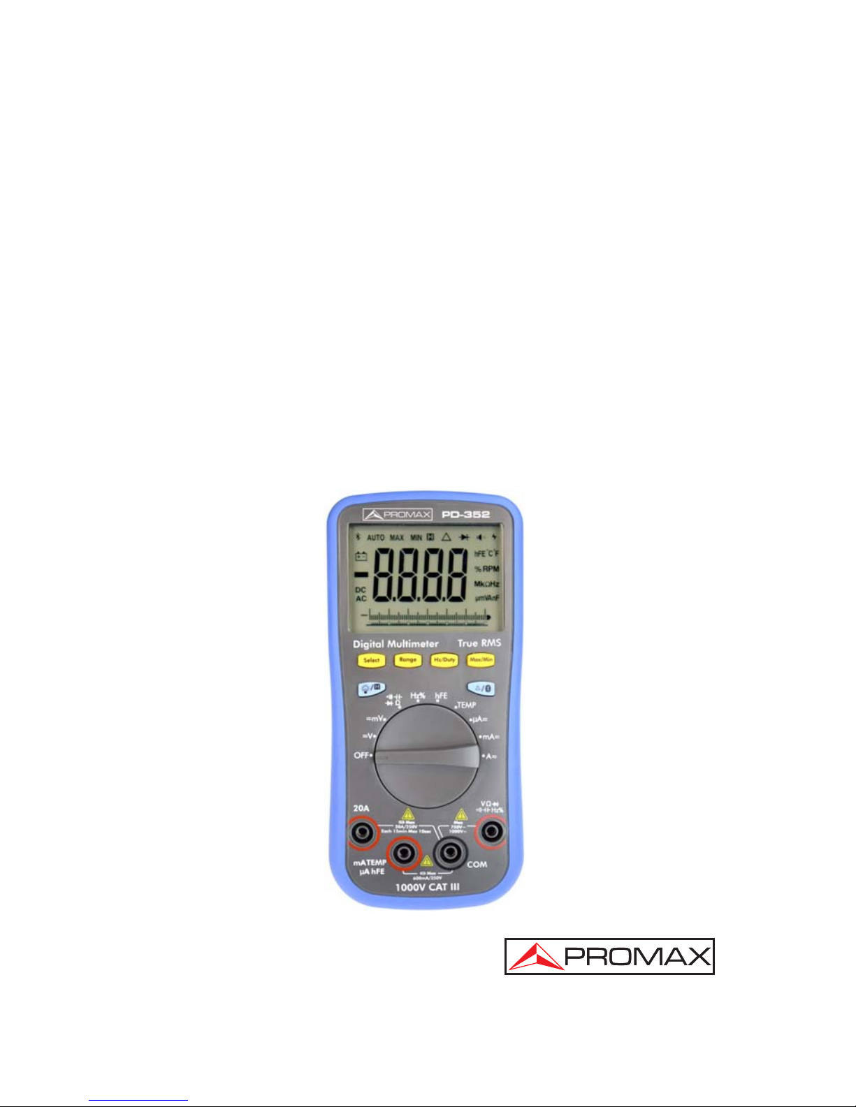
PD-350
PD-351
PD-352
Digital Multimeter
0 MI2107
Page 2
SAFETY NOTES
Read the user’s manual before using the equipment, mainly
"SAFETY RULES" paragraph.
The symbol
on the equipment means "SEE USER’S
MANUAL". In this manual may also appear as a Caution or
Warning symbol.
WARNING AND CAUTION statements may appear in this
manual to avoid injury hazard or damage to this product or
other property.
USER'S MANUAL VERSION
Version Date
1.2 June 2016
Page 3

June 2016
SAFETY RULES
* The safety could not be assured if the instructions
for use are not closely followed.
* This equipment can be used in Overvoltage Category
III installations and Pollution Degree 2
environments.
* When using some of the following accessories use only
the specified ones to ensure safety:
One pair test leads
* Review the state of the test ends before its use.
* Observe all specified ratings of measurement.
* Remember that voltages higher than 60 V DC or 33 V
AC rms are dangereus.
* Use this instrument under the specified environmental
conditions.
* The user is only authorised to:
Battery replacement
Fuses
* On the Maintenance section proper instructions are given.
* Any other change on the equipment should be carried out
by qualified personnel.
* Follow the cleaning conditions described in the
Maintenance paragraph.
* Observe all specified ratings for measurement.
Page 4
June 2016
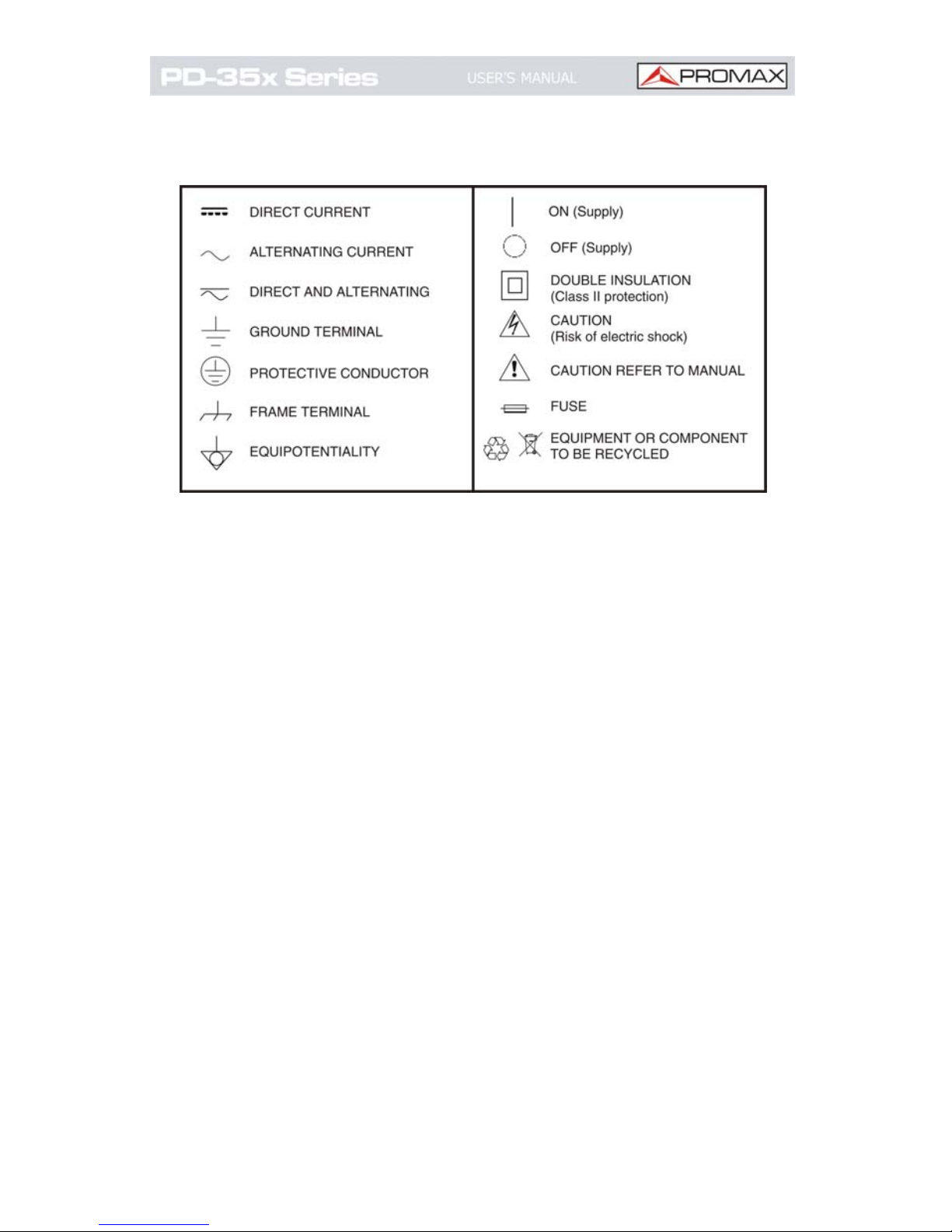
* Symbols related with safety:
Descriptive Examples of Over-Voltage Categories
Cat I Low voltage installations isolated from the
mains.
Cat II Portable domestic installations.
Cat III Fixed domestic installations.
Cat IV Industrial installations.
Page 5

June 2016
TABLE OF CONTENTS
1 Introduction ............................................................1
1.1 Features................................................................ 1
2 Setting Up............................................................... 2
2.1 General Inspecti
on.................................................. 2
2.2 Install the Batteries
................................................3
2.3 Adjusting the Tilt Stand ...........................................4
2.4 Power On ..............................................................4
2.5 Sleep Mode............................................................ 4
2.6 Backlight Control .................................................... 5
2.7 Selecting the Range ................................................ 5
2.8 Description ............................................................6
3 Measurements
....................................................... 12
3.1 Measuring AC or D
C Voltage................................... 12
3.2 Measuring Resi
stance ............................................ 13
3.3 Testing Di
odes ..................................................... 13
3.4 Testing for Continuity............................................ 14
3.5 Measuring Capaci
tance .......................................... 15
3.6 Measuring Freq
uency ............................................ 16
3.7 Measuring Tra
nsistor............................................. 16
3.8 Measuring Tempera
ture ......................................... 17
3.9 Measuring DC or A
C Current................................... 17
4 Tools .................................................................... 19
4.1 Data Hold Mode.................................................... 19
4.2 Capturing Max. and Mi
n. Values .............................. 19
4.3 Making Relative Measurements
............................... 20
4.4 Buzzer Feature
..................................................... 20
5 Bluetooth Function (PD-351 and
PD-352) .................. 22
5.1 System Requirements of
Mobile Devices .................. 22
5.2 Install the application sof
tware ............................... 22
5.3 How to Connect.................................................... 23
5.4 User Interface ...................................................... 26
6 Operations ............................................................ 28
Page 6

June 2016
7 Technical Speci
fications........................................... 32
8 Maintenance.......................................................... 36
8.1 Cleaning the multimeter ........................................ 36
8.2 Replacing the bat
tery ............................................ 36
8.3 Fuse replacement
................................................. 37
Page 7

June 2016 Page 1
Digital Multimeter
PD-35x Series
1 Introduction
1.1
Features
• Data transferring via Bluetooth, interacting with
mobile device to read measurements, analyze via
special chart mode, remote control, voice-out feature;
voice warning supported, which enhances
measurement safety (only in PD-351 and PD-352).
•
5
3
6
digit reading, achieving higher measurement
accuracy than
1
3
2
or
3
3
4
digit counterparts.
• Larger display, easier data-reading; analog bar graph
is displayed synchronously.
• Connect simultaneously with two multimeters
supported via mobile APP.
• Temperature measuring function.
• Backlit-powered screen, more suitable for dark
measurement environment.
• Smart power-off function, extending battery life.
• Thin-tipped test lead (optional) to measure the pins of
small package device.
• True RMS value available (only in PD-352 and
PD-350).
Page 8

Page 2 June 2016
2 Setting Up
2.1
General Inspection
After you get a new multimeter, make a check on the
instrument according to the following steps:
1. Check whether there is any damage caused by
Transportation.
If it is found that the packaging carton or the foamed
plastic protection cushion has suffered serious damage,
do not throw it away first till the complete device and its
accessories succeed in the electrical and mechanical
property tests.
2. Check the Accessories.
The supplied accessories have been already described in
this Manual. You can check whether there is any loss of
accessories with reference to this description. If it is
found that there is any accessory lost or damaged,
please get in touch with the distributor of PROMAX
responsible for this service or the PROMAX local offices.
3. Check the Complete Instrument.
If it is found that there is damage to the appearance of
the instrument, or the instrument can not work
normally, or fails in the performance test, please get in
touch with the PROMAX distributor responsible for this
business or the PROMAX local offices. If there is
damage to the instrument caused by the transportation,
please keep the package.
Page 9
June 2016 Page 3
2.2
Install the Batteries
The multimeter is powered by two 1.5 V AA alkaline
batteries (not included).
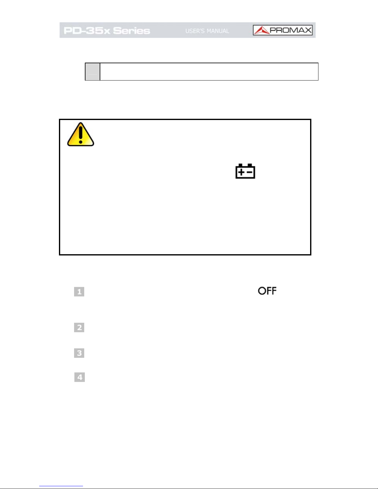
WARNING:
T
o avoid false readings, which
could lead to possible electric
shock or personal injury, replace
the battery as soon as the low
battery indicator
appears.
Before replacing the battery, turn
off the meter,
disconnect test
leads and any connectors from
any circuit under test, remove test
leads from the input terminals.
Use only the specified battery
type.
Use the following procedure to install the batteries.
Ensure that the rotary switch is at the position.
Remove test leads and any connectors from the input
terminals.
Lift the tilt stand and loosen the screws with a suitable
Phillips screwdriver and remove the battery cover.
Observe the battery polarity indicated inside the
battery compartment, Insert the batteries.
Place the battery cover back in its original position
and tighten the screws.
Page 10

Page 4 June 2016
CAUTION:
T
o avoid instruments being
damage from battery leakage,
always remove the batteries and
store them separately if the
multimeter is not going to be used
for a long period.
2.3
Adjusting the Tilt Stand
Pull the tilt- stand outward to its maximum reach (about
85 ° to the meter body).
2.4
Power On
To power ON the multimeter, turn the rotary switch to
any other position except
.
To power OFF the multimeter, turn the rotary switch
to the
position.
2.5
Sleep Mode
The multimeter automatically enters the sleep mode if the
rotary switch is not moved or a key is not pressed for
15 minutes. (When the Bluetooth is activated, this
function is disabled).
Pressing any key will turn the multimeter back to
operation mode from the sleep mode.
One minute before auto power-off, the buzzer will sound
“beep” five times to warn. Before it is shut off, the buzzer
will sound a long ”beep” then shut off.
Page 11
June 2016 Page 5
NOTE: In sleep mode, the multimeter will still consume
a little power. If the multimeter
is not going to
be used for a long period, the power should be
turned off.
2.6
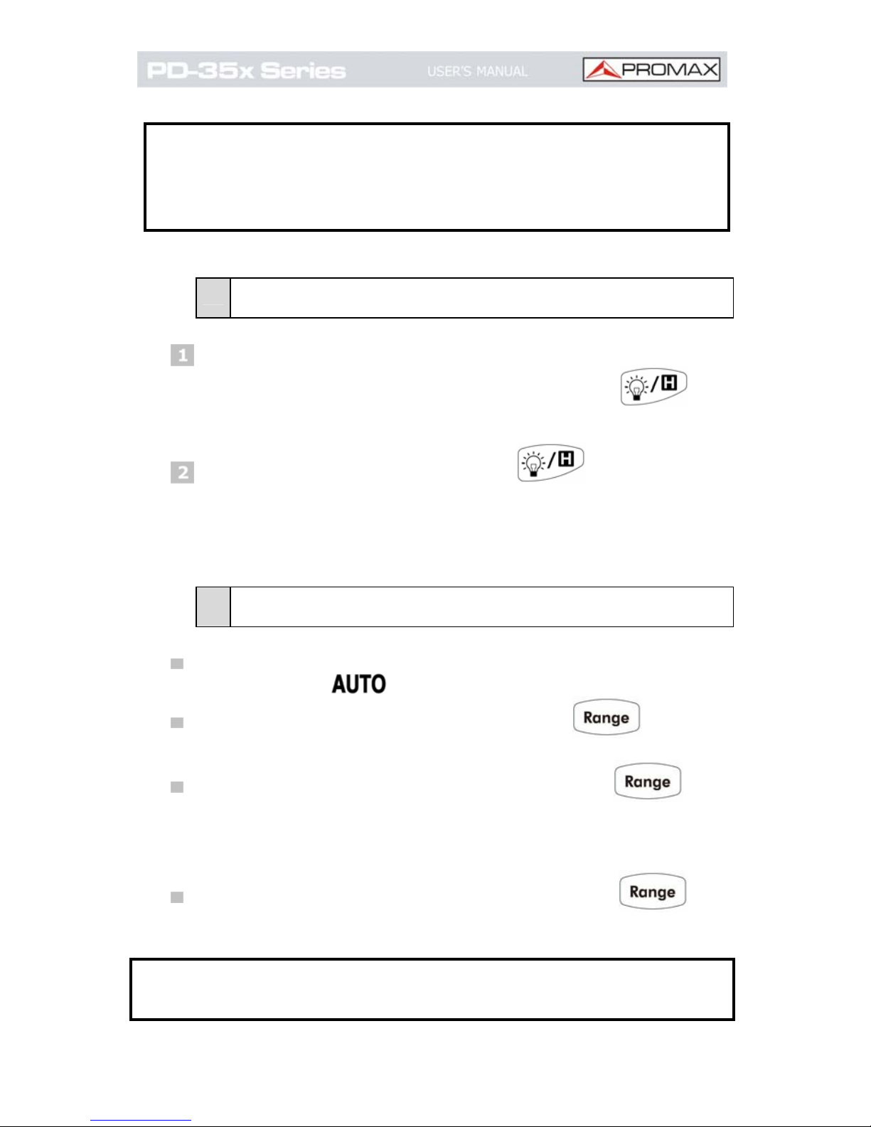
Backlight Control
To view the display in low-light conditions, you can
activate the LCD backlight by pressing
for
more than 2 seconds.
To turn off the backlight, press
for more than
2 seconds.
The backlight will last for 60 seconds.
2.7
Selecting the Range
Auto ranging is set as default when the meter is
powered on,
is displayed.
When auto ranging is enabled, press to enter
the manual range mode.
In manual range, each additional press of sets
the multimeter to the next higher range, unless it is
already in the highest range, at which point the range
switches to the lowest range.
When manual range is enabled, press for
more than 2 seconds to enter the auto ranging mode.
Note: Manual range is not available when measuring
capacitance.
Page 12
Page 6 June 2016
2.8
Description
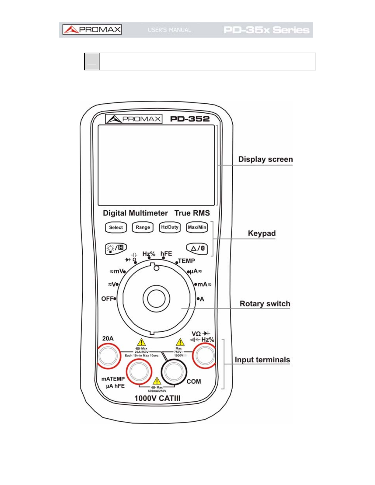
Front panel
Figure 1. Front Pannel
Page 13
June 2016 Page 7
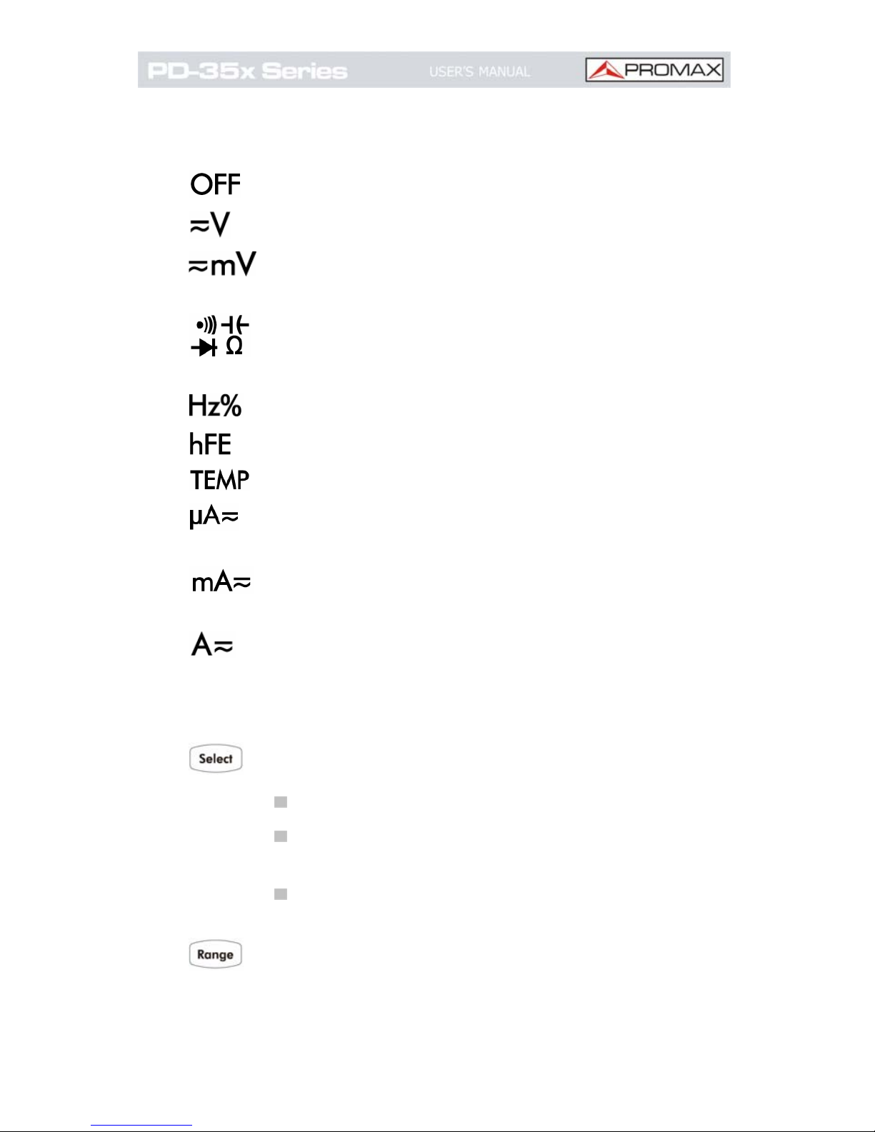
Rotary switch
Power off.
DC or AC voltage measurement.
DC or AC voltage measurement (up to 600
millivolts).
Continuity test, Capacitance measurement,
Diode test, Resistance measurement.
Frequency measurement.
Transistor measurement.
Temperature measurement.
DC or AC current measurement (up to 600
microamperes).
DC or AC current measurement (up to 600
milliamperes).
DC or AC current measurement.
Keypad
Select function:
Select DC or AC
Select °C or °F during temperature
measurements
Select Resistance / Diode / Continuity /
Capacitance
Auto/Manual range.
Page 14
Page 8 June 2016
Select frequency/duty cycle.
Capturing Max. and Min. Values.
Backlight, Data Hold.
Relative Measurements, Bluetooth (PD-352).
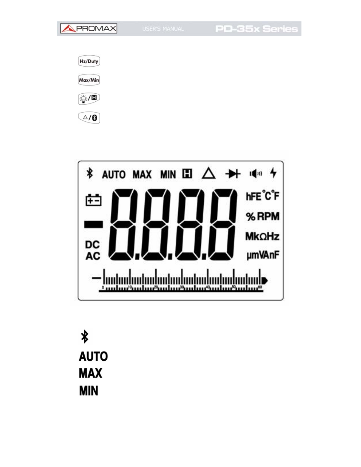
Display screen
Figure 2. Display screen.
Bluetooth enabled.
Auto range.
Maximum reading.
Minimum reading.
Page 15

June 2016 Page 9
Data hold enabled.
Relative enabled.
Diode test selected.
Continuity test selected.
Battery is low.
DC.
AC.
Measurement display ("OL" is short for
overload, indicates the reading exceeds the
display range).
Measuring units.
Analog bar graph.
Measurement units
Sign Description
M
Mega 1E+06 (1000000)
k
kilo 1E+03 (1000)
m
milli 1E–03 (0.001)
μ
micro 1E–06 (0.000001)
n
nano 1E–09 (0.000000001)
Page 16

Page 10 June 2016
Sign Description Measurement type
°C
Degree Celsius
°F
Degree Fahrenheit
Temperature
V
Voltage Voltage
A
Ampere Current
Ω
Ohm Resistance
Hz
Hertz Frequency
%
Percent, Duty cycle
F
Farad Capacitance
hFE
Current Amplification
Factor
Transistor
Input terminals
The terminal connections for the different measurement
functions of the multimeter are described in the table below.
WARNING: Before starting any
measurement, observe the
rotary switch position of the
multimeter, and then connect
the test leads to the correct
terminals.
CAUTION: To avoid damaging the
multimeter, do not exceed the
rated input limit.
Page 17

June 2016 Page 11
Rotary
switch
position
Input terminals
Overload
protection
750 VAC/1000
VDC
250 VDC or
Equivalent
voltage RMS
250 VAC or
Equivalent
voltage RMS
1 A / 250 V,
fast-acting
fuse
20 A / 250 V,
fast-acting
fuse
Page 18

Page 12 June 2016
3 Measurements
3.1
Measuring AC or DC Voltage
WARNING: Do not measure any voltage of
over 1000 VDC or 750 VAC rms to
avoid instrument damage or
electric shock.Do not apply more
than 1000 VDC or 750 VAC rms
between the common terminal and
the earth ground to avoid
instrument damage or electric
shock.
This multimeter displays DC voltage values as well as their
polarity. Negative DC voltages will display a negative sign on
the left of the display.
DC voltage ranges are 60.00 mV, 600.0 mV, 6.000 V,
60.00 V, 600.0 V, 1000 V.
AC voltage ranges are 60.00 mV, 600.0 mV, 6.000 V,
60.00 V, 600.0 V, 750 V.
Rotate the rotary switch to or . Default is DC
measurement mode,
will be displayed. Press
to switch into AC measurement mode,
will be
displayed.
Connect the black test lead to the terminal and
the red test lead to the
terminal.
Probe the test points and read the display. Press
to enable and cycle through the manual ranges.
Page 19

June 2016 Page 13
3.2
Measuring Resistance
CAUTION:
T
o avoid possible damage to your
multimeter or to the equipment
under test, disconnect the circuit
power and discharge all highvoltage capacitors before
measuring resistance.
Resistance ranges are 600.0 Ω, 6.000 kΩ, 60.00 kΩ,
600.0 kΩ, 6.000 MΩ, and 60.00 MΩ.
Rotate the rotary switch to .
Connect the black test lead to the terminal and
the red test lead to the
terminal.
Probe the test points and read the display. Press
to enable and cycle through the manual ranges.
3.3
Testing Diodes
CAUTION:
T
o avoid possible damage to your
multimeter or to the equipment
under test, disconnect the circuit
power and discharge all highvoltage capacitors before testing
diodes
Rotate the rotary switch to . Press once to
enter diode testing mode,
will be displayed.
Connect the black test lead to the terminal and
the red test lead to the
terminal.
Page 20

Page 14 June 2016
Connect the red test lead to the positive terminal
(anode) of the diode and the black test lead to the
negative terminal (cathode). The cathode of a diode is
indicated with a band.
Read the diode forward bias. If the test lead
connection is reversed, the multimeter will display
"OL".
3.4
Testing for Continuity
CAUTION:
T
o avoid possible damage to your
multimeter or to the equipment
under test, disconnect the circuit
power and discharge all highvoltage capacitors before testing
for continuity.
Rotate the rotary switch to . Press twice
to enter continuity testing mode,
will be
displayed.
Connect the black test lead to the terminal and
the red test lead to the
terminal.
Probe the test points to measure the resistance in the
circuit. If the reading is below 30 Ω, the multimeter
will beep continuously.
Page 21

June 2016 Page 15
3.5
Measuring Capacitance
CAUTION: To avoid possible damage to the
multimeter or to the equipment
under test, disconnect circuit
power and discharge all highvoltage capacitors before
measuring capacitance. Use the
DC voltage function to confirm
that the capacitor is fully
discharged.
Capacitance ranges are 40.00 nF, 400.0 nF, 4.000 uF,
40.00 uF, 400.0 uF, 4000 uF.
Note: For the 4000 uF range, the measuring duration should
be over 30 seconds.
Rotate the rotary switch to . Press three
times to enter capacitance measuring mode, the
Farad units will be displayed.
Connect the black test lead to the terminal and
the red test lead to the
terminal.
Probe the test points and read the display.
Page 22

Page 16 June 2016
3.6
Measuring Frequency
Frequency ranges are 9.999 Hz, 99.99 Hz, 999.9 Hz,
9.999 kHz, 99.99 kHz, 999.9 kHz, and 9.999 MHz.
Rotate the rotary switch to .
Connect the black test lead to the terminal and
the red test lead to the
terminal.
Probe the test points and read the display.
Press to switch between the frequency and
duty cycle measurements.
When measuring AC voltage or AC current, press
to
cycle through frequency measuring, duty cycle measuring,
and original measuring.
3.7
Measuring Transistor
WARNING:
T
o avoid electrical shock or damage
to the instrument, do not apply
more than 250 VDC or 250 VAC
rms between the
terminal and
the
terminal.
Rotate the rotary switch to .
Connect the “+” plug of the multi-functional test
socket to the
terminal and the “COM” plug to
the
terminal).
Determine whether the transistor is NPN or PNP type
and locate the Emitter, Base and Collector leads.
Insert leads of the transistor into the corresponding
holes of the multi-functional test socket.
Page 23

June 2016 Page 17
Read the hFE value.
3.8
Measuring Temperature
Rotate the rotary switch to .
Connect the red connection of the K-type
thermocouple to the
terminal and the black
connection to the
terminal.
Probe the test points and read the display. Press
to change the temperature units between
or
.
3.9
Measuring DC or AC Current
WARNING: Never attempt an in-circuit current
measurement where the opencircuit potential to earth is greater
than 250 V. Doing so will cause
damage to the multimeter and
possible electric shock or personal
injury.
CAUTION: To avoid possible damage to the
multimeter or to the equipment
under test, check the multimeter’s
fuse before measuring current.
Use the proper terminals, function,
and range for your measurement.
Never place the test leads in
parallel with any
circuit or
component when the leads are
plugged into the current terminals.
Page 24

Page 18 June 2016
Current ranges are 600.0 μA, 6000 μA, 60.00 mA, 600.0 mA,
6.000 A, and 20.00 A.
Turn off the power of the measured circuit. Discharge
all high- voltage capacitors.
Connect the black test lead to the terminal. For
currents below 600 mA, connect the red test lead to
the
terminal; for currents within 600 mA –
20 A, connect the red test lead to the
terminal.
Rotate the rotary switch to the appropriate position
according to the measurement range,
,
, or
.
Disconnect the circuit path to be tested. Connect the
black test lead to one side of the circuit (with a lower
voltage); connect the red test lead to the other side
(with a higher voltage). Reversing the leads will
produce a negative reading, but will not damage the
multimeter.
Select DC or AC measurement mode. Default is DC
measurement mode,
will be displayed. Press
to switch into AC measurement mode,
will be displayed.
Turn on the power of the measured circuit, and read
the display. Press
to enable and cycle through
the manual ranges. If "OL" is displayed, it indicates
the input exceeds the selected range and the rotary
switch should be set to the position with higher range.
Turn off the power of the measured circuit and
discharge all high-voltage capacitors. Remove the test
leads and restore the circuit to the original condition.
Page 25

June 2016 Page 19
4 Tools
4.1
Data Hold Mode
Press
to freeze the display during
measurement,
will be shown on the display.
Press again to exit this mode.
Note: This function is not available when measuring diodes
and transistor.
4.2
Capturing Max. and Min. Values
In MAX mode, the measured maximum value will be held; In
MIN mode, the measured minimum value will be held.
Press to cycle between the MAX mode and
MIN mode.
Press for more than 2 seconds to exit the
mode.
In this mode, the manual range mode will be activated
automatically. Analog bar graph is not displayed. Auto
power-off function is disabled.
Note: This function is not available when measuring diodes,
capacitance, transistor, and frequency.
Page 26

Page 20 June 2016
4.3
Making Relative Measurements
When making relative measurements, reading is the
difference between a stored reference value and the input
signal.
Press to enter the relative mode. The
measurement value when pressing
is stored
as the reference value. In this mode, REL
(current
reading) = input value - reference value.
Press it again to exit the mode. In relative
measurement, the manual range mode will be
activated automatically. (The relative measurement
should be carried out under a certain range, that is,
this function is only available under the manual range
mode.) Analog bar graph is not displayed.
Note: This function is not available when measuring diodes,
transistor, and frequency.
4.4
Buzzer Feature
Press the function key, the buzzer will sound “Be…” in
short.
One minute before Auto Power-off the buzzer will
sound “beep” five times to warn. Before it is shut off,
the buzzer will sound a long ” beep” then shut off.
The buzzer will sound “beep…” continuously to warn
when the measured DC voltage is higher than 1000 V,
AC voltage is higher than 750 V, or the measured
DC/AC mV mode is higher than 600.0 mV.
Page 27

June 2016 Page 21
The buzzer will sound long when the short circuit
resistance is less than about 30W during the
continuity test.
When the Bluetooth function is time out, the buzzer
will sound “beep” two times.
Page 28
Page 22 June 2016
5 Bluetooth Function (PD-351 and PD-352)
PD-351 and PD-352 multimeter supports communications
with Android based smart device through Bluetooth. You can
use the free application software on the Android based smart
devices to monitor the measurements, perform remote
control, view trending graphs, etc. The recorded data can be
saved as CSV file. More than one meters can be connect
simultaneously.
Note: Bluetooth connectivity works over a range of about 10
meters. The work range is much longer in open-sided
and non-occluded wide range environment, even up
to 20 meters. If the Bluetooth function in the
multimeter is idle for 10 minutes, the Bluetooth will
be turned off automatically. Before turning off, the
buzzer will sound “beep” two times.
5.1
System Requirements of Mobile Devices
Android devices with Bluetooth connectivity 4.0.
Android Versions: 4.4 and above.
5.2
Install the application software
Install the free PROMAX application software
(Multimeter.apk). It can be downloaded from here:
Scan QR Codes below with your Android based smart
device to install the app.
Page 29

June 2016 Page 23
Visit www.promax.es/smartphone-apps/pd-35x to
download APK file and install into the device.
Note: To allow the installation of this android application
from a place other than the official website of Google
"Play", on your mobile device go to "Settings" /
"Security" and enable the "Unknown sources" option.
5.3
How to Connect
Turn on the multimeter, press and hold until
appear on the display.
Launch the application .
Click the icon on the top left of the screen to launch
device connection.
Figure 3.
Page 30

Page 24 June 2016
If the Bluetooth function is activated, skip this step; if
not, a dialog box (similar to figure below) will ask
whether to turn on Bluetooth. Click "Yes".
Figure 4.
Now, the blueetooh will try to detect the multimeter.
Click to scan to try again.
Figure 5.
Page 31

June 2016 Page 25
In the list of devices should appear PD-351 or
PD-352. Select the right one to pair. After pairing a
confirmation message should appear on screen.
Figure 6.
You can repeat this procedure to connect the mobile
device to a second multimeter, by clicking on "No
device" on the top right of the screen and following
the steps described above.
Page 32

Page 26 June 2016
5.4
User Interface
Figure 7.
Figure 8.
Page 33

June 2016 Page 27
Function Description Table
Display Function
DC Direct Current
AC Alternating Current
RES Measuring Resistance
DIO Testing Diodes
BEEP Testing for Continuity
Display Function
CAP Measuring Capacitance
Hz Measuring Frequency
DUT Measuring Duty Cycle
hFE Measuring Transistor
TEMP Measuring Temperature
Page 34

Page 28 June 2016
6 Operations
Customize the meter name
The device name of meter can be customized. Press and
hold the name on the top left of the scree, a dialog box
below will pop up. You can input the customized name,
this name will be memorized in the device. If this meter
is connected to the same device next time, the
customized name will be shown. If this meter is
connected to another device, the name is still the default
one or the customized name to the connected device.
Figure 9.
Add meter: In double view, click softkey.
Select meter: In single or double view, click or
softkey.
Disconnect meter: In single or double view, click
or the meter name.
Remote Control: In single view, the control softkeys
(blue background softkeys, as Hold, Rel, Select, etc.)
can be short or long pressed to perform control, just as
press the corresponding keys of multimeter.
Page 35

June 2016 Page 29
Voice out function
Provide an audible out of the readings through the textto-speech (TTS) engine on your Android device. Click
the
icon on the top right of the screen to turn on
voice out. Click
to turn off. In settings menu on your
Android device, you can set the language-specific voice
for the spoken text, or speech rate etc.
You may change to different voices by installing
different TTS engines.
About: Click , and click "About", the following
interface is shown.
Figure 10.
Page 36

Page 30 June 2016
Data Graph and Table: Click to view data graph
and table. Click
to show setting menu.
Figure 11.
Setting menu
Softkey Description
Open local
file
Read the saved file (.CSV)
Save data
Save the displayed data into .CSV file
Share
Share the measurements via the
installed sharing apps
Clear data
Clear the data displayed
Setting
Sampling Interval: Set the sampling
interval in the application software.
Enable Period: Log data within the
defined period.
Record Period: Define the period time
if the period is enabled.
Fill: Check to fill the area as blue below
the data line.
Exit
Exit the APP
Page 37

June 2016 Page 31
Note: In trending graph, you can pinch the screen to zoom.
The Y axis (value) can be zoomed by gesturing along
the up-down direction, and the X axis
(time) can be
zoomed by gesturing along the left-right direction.
Page 38

Page 32 June 2016
7 Technical Specifications
All these specifications apply to the multimeter unless
otherwise explanation.
Standard conditions: The environment temperature is
18 ºC to 28 ºC, the relative humidity is less than 80%.
Function
Measurement
Range
Resolution
Accuracy
mV 60.00 mV / 600.0 mV 0.01 mV
60.00 mV / 600.0 mV
/ 6.000 V / 60.00 V
0.1 mV
DC
Voltage
(V)
V
600.0 V / 1000 V 0.1 V
±(0.8%+2dig)
mV 60.00 mV / 600.0 mV 0.01 mV ±(0.8%+2dig)
60.00 mV / 600.0 mV
/ 6.000 V / 60.00 V
1 mV ±(0.8%+2dig)
AC
Voltage
(V)
V
600.0 V / 750 V 0.1 V ±(1%+3dig)
μA 600.0 μA 0.1 μA ±(0.8%+2dig)
mA
600.0 μA / 6.000 mA /
60.00 mA / 600.0 mA
/ 6.000A
0.01 mA
±(0.8%+2dig)
DC
Current
(A)
A
20.00 A
1
1 mA
±(1.2%+3dig)
μA 600.0 μA 0.1 μA ±(1%+3dig)
mA
600.0 μA / 6.000 mA /
60.00 mA / 600.0 mA
/ 6.000 A
0.01 mA
±(0.8%+2dig)
AC
Current
(A)
A
20.00 A
1
1 mA
±(2%+3dig)
600.0 Ω / 6.000 kΩ/
60.00 kΩ / 600.0 kΩ/
6.000 MΩ / 10.0 0 MΩ
0.1 Ω
±(0.8%+2dig)
Resistance (Ω)
60.00 MΩ 0.01 MΩ ±(2%+3dig)
1
When measuring current, for 10 A to 15 A, the measuring duration should not be over 2 minutes
within 10 minutes, and in this 10 minutes, no other current should flow through except within the
measuring duration; for 15 A to 20 A, the measuring duration should not be over 10 seconds within
15 minutes, and in this 15 minutes, no other current should flow through except within the measuring
duration.
Page 39

June 2016 Page 33
Function
Measurement
Range
Resolu
-tion
Accuracy
40.00 nF 0.01 nF ±(2.5 %+3dig)
400,0 nF /
4,000 μF/ 40,00 μF
0.1 nF
±(2.5 %+3dig)
Capacitance (F)
400.0 μF / 4000 μF
2
0.1 μF
±(3 %+5dig)
Frequency3 (Hz)
9,999 Hz /
99,99 Hz /
999,9 Hz /
9,999 kHz /
99,99 kHz /
999,9 kHz /
9,999 MHz
1 mHz ±(0.8 %+2dig)
0,1% - 99,9%
(Typical: Vrms=
1 V, f=1 kHz)
±(1.2 %+3dig)
Duty Cycle4 (%)
0,1% - 99,9%
(≥1 kHz)
0.1 %
±(2.5 %+3dig)
-50 °C to 400 °C
1 °C
±(2.5 %+3dig)
Temperature
(°C/°F)
-58 °F to 752 °F
1 °F
±(4.5 %+5dig)
2
When measuring capacitance, for the 4000 uF range, the measuring duration should be over 30
seconds.
3
When measuring frequency, the typical waveform is Square or Sine. The signal meets the following
conditions.
Frequency Amplitude (rms)
1 Hz – 4 MHz 100 mV
4 MHz – 8 MHz ≥200 mV
8 MHz – 10 MHz ≥300 mV
4
When measuring duty cycle, the typical waveform is Square.
Page 40

Page 34 June 2016
Display 6000
PD-351 (40 - 400) Hz
Frequency Response
(Hz)
PD-352; PD-350 (40 – 10k) Hz
Sample rate for
digital data
3 times/second
Sample rate for
analog bar graph
30 times/second
PD-351; PD-352 √
Bluetooth
PD-350 Without
Auto ranging √
True RMS PD-352; PD-350
Diodes Test √
Measuring
Transistor
√
Sleep Mode √
Continuity Test √
Low battery
indication
√(The "
" is displayed when the battery is
under the proper operation range.)
Data Hold √
Relative
Measurement
√
MAX/MIN Value √
LCD Backlight √
Analog bar graph 61 Segments
Input Protection √
Input Impedance 10 MΩ
Page 41

June 2016 Page 35
Battery
3 V (1.5 V × 2) AA alkaline batteries (not
included)
LCD Size 69 mm * 52 mm
Weight (without
package)
0.32 kg
Dimension 85 mm * 185 mm * 30 mm
Working
temperature
0 °C to 40 °C
Storage
temperature
-10C o 60 °
Relative Humidity ≤ 80%
Altitude
Operating: 3,000 m
Non-operating: 15,000 m
Note: Equipment specifications are set in these environmental
operating conditions. Operation outside these specifications
are also possible. Please check with us if you have specific
requirements.
RECOMMENDATIONS ABOUT THE PACKING
It is recommended to keep all the packing material in order to
return the equipment, if necessary, to the Technical Service.
Page 42

Page 36 June 2016
8 Maintenance
8.1
Cleaning the multimeter
Wipe the case occasionally with a damp cloth. DO NOT use
chemicals, cleaning solvents, abrasives or detergents.
8.2
Replacing the battery
This meter is powered by a 6F22/LR22 or equivalent 9-volt
battery.
When the multimeter displays the "
+
" the battery must be
replaced to maintain proper operation. Use the following
procedure to replacing the battery:
1. Unscrew and remove the rear panel with the aid of a
suitable Phillips screwdriver.
2. Remove the battery and replace it by a new one of
9 V 6F22/LR22 type.
3. Back to placing the rear panel and screw it again.
Page 43

June 2016 Page 37
8.3
Fuse replacement
WARNING: Disconnect all the test leads before initiating
the fuse replacement process. Power off the
instrument.
Fuses are located inside the instrument. In order to replace them
you must follow these instructions:
1. Remove the holster
2. Unscrew and remove the rear panel using a Phillips suitable
screwdriver.
3. Remove old fuses and replace them by the new ones.
Fuses must be:
1 A F250V
USING DIFFERENT TYPE OF FUSES COULD
DAMAGE THE INSTRUMENT.
4. Back to placing the rear panel and screw it.
5. Put the holster back in place
Page 44

PROMAX ELECTRONICA, S. L.
Francesc Moragas, 71-75
08907 L’HOSPITALET DE LLOBREGAT (Barcelona)
SPAIN
Tel. : 93 184 77 00
* Tel. Intl. : (+34) 93 184 77 02
Fax : 93 338 11 26
* Fax Intl. : (+34) 93 338 11 26
http://www.promaxelectronics.com
e-mail: promax@promaxelectronics.com
 Loading...