

Page 1
OS-782
Test Equipment Depot - 800.517.8431 - 99 Washington Street Melrose, MA 02176
TestEquipmentDepot.com
DIGITAL OSCILLOSCOPE & MULTIMETER
- 0 MI1737 -
Page 2

SAFETY NOTES
Read
the user’s manual before using the equipment, mainly " SAFETY
RULES " paragraph.
The symbol
this manual may also appear as a Caution or Warning symbol.
Warning and Caution statements may appear in this manual to avoid
injury hazard or damage to this product or other property.
on the equipment means "SEE USER’S MANUAL". In
Page 3

User’s Manual. OS-782
TABLE OF CONTENTS
1 GENERAL.................................................................................................................. 1
Description .......................................................................................................... 1
1.1
1.2
Specifications Oscilloscope.................................................................................2
1.3
Specifications Multimeter .................................................................................... 5
SAFETY RULES........................................................................................................ 7
2
2.1
General................................................................................................................7
2.2
Descriptive Examples of Over-Voltage Categories.............................................9
DESCRIPTION FOR FRONT PANEL AND KEYS ..................................................11
3
4
USING THE OSCILLOSCOPE ................................................................................ 13
4.1
Power-Up the oscilloscope................................................................................ 13
4.2
Charging the oscilloscope.................................................................................13
4.3
Oscilloscope Operation Window ....................................................................... 14
Navigating a Menu ............................................................................................ 16
4.4
4.5
Manually Setting the Vertical System, Horizontal System and Trigger Position17
4.6
Resetting the Oscilloscope................................................................................ 20
4.7
Displaying an Unknown Signal with Auto Set ...................................................20
4.8
Automatic zero-returning of trigger horizontal position and trigger level position.....21
4.9
Automatic Measurements..................................................................................21
4.10
Freezing the Screen .......................................................................................... 22
4.11
Setting the Vertical CH1 and CH2.....................................................................23
4.11.1
Setting the Channel Coupling .....................................................................24
4.11.2
Make Open and Close Settings on Channel...............................................25
Adjusting the Probe Scale........................................................................... 25
4.11.3
4.11.4
4.12
4.13
4.14
4.15
4.16
4.17
4.18
4.19
4.20
4.21
4.22
4.23
4.24
Setting of Inverted Waveform ..................................................................... 26
MATH function “MATH” ..................................................................................... 26
Setting the Trigger System. TRIGGER Function............................................... 27
Triggering Control.............................................................................................. 28
4.14.1
Edge triggering............................................................................................ 29
Description..............................................................................................................29
4.14.2
Video triggering...........................................................................................30
Acquiring Mode Setting ..................................................................................... 33
Display Setting ..................................................................................................33
Settings...................................................................................................................33
4.16.1
Display Style ...............................................................................................34
4.16.2
Persistence .................................................................................................34
4.16.3
XY mode .....................................................................................................35
Waveform Saving Setups..................................................................................35
Function Setting Menu ......................................................................................36
Making Automatic Measurements.....................................................................37
Setting the Cursor Measurements..................................................................... 40
Autoscale........................................................................................................... 42
System State Menu........................................................................................... 45
Horizontal axis setting. HORIZONTAL function ................................................46
Data transmission to the PC.............................................................................. 47
English
Page 4

User’s Manual. OS-782
USING THE MULTIMETER.....................................................................................49
5
5.1
About this chapter ............................................................................................. 49
5.2
Making Meter Connections................................................................................49
5.3
Multimeter Operation Window...........................................................................49
5.4
Making Multimeter Measurements.................................................................... 51
Measuring Resistance Values ....................................................................51
5.4.1
5.4.2
Making a Diode Measurement. ................................................................... 51
5.4.3
On-off test ...................................................................................................52
5.4.4
Making a Capacitance Measurement .........................................................53
5.4.5
Making a DC voltage Measurement (VDC)................................................. 54
5.4.6
Making a AC voltage Measurement (VAC)................................................. 54
5.4.7
Making a DC current Measurement (AAC) .................................................55
5.4.8
Making an AC Current Measurement .........................................................57
5.5
Freezing the Readings. .....................................................................................58
5.6
Taking a relative measurement .........................................................................59
Selecting automatic/manual range adjustment ................................................. 60
5.7
TROUBLE SHOOTING............................................................................................ 61
6
MAINTENANCE AND CLEANING........................................................................... 63
7
7.1
Basic maintenance ............................................................................................63
Cleaning ............................................................................................................63
7.2
7.3
Storage of oscilloscope .....................................................................................63
7.4
Substitution of the battery of lithium. .................................................................63
Page 5

USER’S MANUAL. OS-782
Oscilloscope & Multimeter
Digital Storage
OS-782
1 GENERAL
1.1 Description
The OS-782 poliscope has two measurement instruments built-in: one digital
oscilloscope and one multimeter. Its rugged construction, small size, lightweight and
battery-powered, lead it to be a handheld instrument ideal to carry out multiple external
measurements, where to work with conventional equipments it is very uncomfortable. It
is very useful to measure the electrical magnitudes and to repair electronic equipments
given its large diversity of functions, which causes that it become an useful tool in
laboratories, as well as for R&D and training activities.
The measurement carried out by the equipment appears on a hi-resolution LCD
with backlight.
Their basic characteristics in each one of their operating modes are:
• Two-channels oscilloscope with bandwidth of 20 MHz.
• Sampling rate of 100 MS/s.
• Trigger: TV and edge.
• 20 automatic measurements modes.
• Auto-scale function.
• Memory depth of 6k points by channel.
• USB port.
• Digital Multimeter of 3 ¾ for measurements of R, V, A and C.
• AC adapter and LI-ion battery.
• Display LCD colour of 3.8 " with backlight, 320x240 pixels.
• Vertical and horizontal cursors.
English
Page 1 02-2010
Page 6

USER’S MANUAL. OS-782
1.2 Specifications Oscilloscope
Only if another instructions are provided, are all technical specifications applicable
to the probe with the 10X attenuation switch setting and the HDS series digital type
oscilloscope. In order to be up to these specifications, the oscilloscope should meet the
following requirement.
• The instrument should operate continuously for more than 30 minutes under
be up to.
SAMPLING
Sampling modes Normal sampling.
Sampling rate 100 MSa/s.
INPUT
Input coupling DC, AC, Ground.
Input impedance 1MΩ ± 2 % connected in parallel with 20pF
Probe attenuation coefficient 1x, 10x, 100x, 1000x.
Max. Input voltage 400V (peak).
Channel delay time(typical) 150 ps.
HORIZONTAL
Sampling rate range 10S/s~100MS/s.
Waveform interpolation (sin x)/x.
Record length 6 K points on each channel.
Scanning speed range (S/div) 5ns/div~100 s/div, stepping in the “1- 2.5 - 5“.
Sampling rate and relay time
accuracy ±100ppm(any time interval which is equal to or
Time interval (T) measurement
Accuracy full bandwidth l Single: ± (1 sampling interval time+100 ppm
the specified operating temperature.
• If the operating temperature range of variation is up to or larger than 5
Celsius degrees, the system function menu must be opened to make the
system perform a “self - calibration” procedure.
Except those specifications marked with the word “Typical”, all specifications can
Peak detection.
Average value.
± 5 pF.
larger than 1ms).
reading+0.6 ns)>average 16: ±(1 sampling
interval time +100 ppm reading+0.4 ns).
02-2010 Page 2
Page 7

USER’S MANUAL. OS-782
VERTICAL
Analog digital converter (A/D) With the resolution of 8 bits, make sampling on
both channels synchronously.
Sensitivity range (V/div) 5mV/div~5V/div at the input BNC.
Displacement range ±50 V(500 mV~5 V), ±2 V(5 mV~200 mV).
Analog bandwidth 20 M.
Single bandwidth Ancho de banda completo.
Low frequency response ≥5Hz (at the BNC ).
(coupling, AD, -3dB
Rise time ≤17.5ns.
(typical one at the BNC)
DC gain accuracy ±5 %.
DC measurement accuracy The voltage difference (V) between any two.
(average value sampling mode) points on the waveform after averaging the
captured waveforms more than16: ±(5%
reading + 0.05 divisions).
Trigger
Trigger sensitivity (Edge triggering)
DC coupling CH1 and CH2: 1div(DC~ full bandwidth).
AC coupling Same as the DC coupling when it is equal to or
larger than 50Hz.
Triggering lever range ±6 divisions from the screen center.
Triggering level accuracy ±0.3 divisions
(typical) which is applicable to
the signal with rise and fall time
equal to or longer than 20ns
Trigger displacement 655 divisions for pre-triggering and 4 divisions
for post- triggering.
Trigger Holdoff range 100 ns~10 s.
Make a 50% level setting (Typical). Operation with the input signal frequency equal
to or larger than 50Hz.
Trigger sensitivity (Video 2 divisions of peak-to-peak value.
Triggering and typical mode)
Signal system and line/field Support the NTSC, PAL and SECAM frequency
(Video triggering mode) broadcasting systems
of any field or line frequency.
Measurement
Cursor measurement Voltage difference (∆V) and time difference
(∆T) between cursors (∆V).
Auto measurement Peak-to-peak value, average value, root mean
square value, Frequency, cycle period, Vmax,
Vmin,Vtop, Vbase, Vamp, Overshoot, Preshoot,
RiseTime, Fall Time, +Width, -Width, +Duty,
-Duty, Delay A B and Delay B A.
English
Page 3 02-2010
Page 8

USER’S MANUAL. OS-782
GENERAL SPECIFICATIONS
Display
Display type 3.8’’ color LCD display.
Display resolution 320 (horizontal) x 240 (vertical) pixels.
Power consumption 4096 colors.
Mechanical features
Dimensions 180 (W) × 115 (H) × 40 (D) mm.
Weight 0.645 kg.
Power supply
Internal 7.4 V Li-Ion Built-in Rechargeable battery.
External Means network adapter included. For Europe
and other countries.
Input 100-240 VAC 50 Hz / 6W.
Working environment
Temperature Operation 0 to 50 °C.
Power adapter 0 to 40 °C.
Storage Temperature -20 to +60 °C.
Humidity in operation
0 to 10 °C no condensation.
10 to 30 °C 95 %
30 to 40 °C 75 %
40 to 50 °C 45 %
Humidity in storage
0 to 10 °C no condensation
ACCESSORIES
Two 1:1 (10:1) passive oscilloscope probes of 1.2 meters long SA016 x1 x10.
A pair of test leads of multimeter PP013.
One communication cable for USB port.
A measuring extension module for small current
A measuring extension module for small capacitance.
One AC power adapter for Europe and other countries (AL782)
A User Manual.0 MI1452
An operational optical disk.
A software CD.
02-2010 Page 4
Page 9
USER’S MANUAL. OS-782
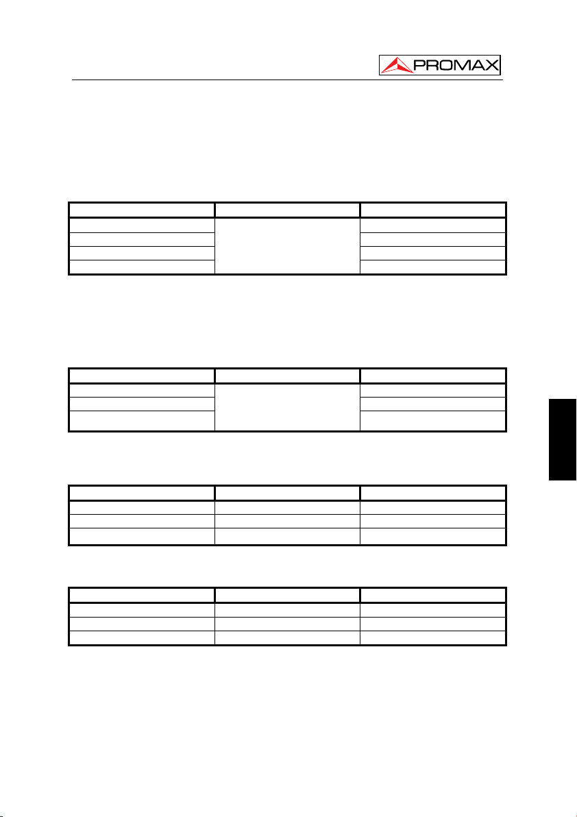
1.3 Specifications Multimeter
Maximum tension of the points of measure to land 400V CAT II
Voltage (VDC)
Input Impedance: 10MΩ
Range Accuracy Resolution
400 mV
4.000 V 1 mV
40.00 V 10 mV
400.0 V
Input protection 1000 VDC or peak AC
Voltage (VAC)
Input Impedance: 10M Ω.
Frequency range: from 40 Hz to 400 Hz.
Display: Virtual value of the sine wave.
Range Accuracy Resolution
4.000 V 1 mV
40.00 V 10 mV
400.0 V
Input protection 750 VDC or peak AC
Direct Current (ADC)(1)
Range Accuracy Resolution
40.00 mA ± 1% ± 1 digit 10 uA
400.0 mA ± 1.5% ± 1 dígito 100uA
20A(2)
± 1% ± 1 digit
± 1% ± 3 digits
± 3% ± 3 dígitos 10 mA
100 µV
100 mV
100 mV
Alternating Current (AAC) (1)
Range Accuracy Resolution
40.00 mA ± 1.5% ± 3 digits 10 uA
400.0 mA ± 2% ± 1 digit 100 uA
20A(2)
(1) ATENTION: Not to overcome in any case 400mA or 20A respectively.
(2) With the extension module of measure of current.
± 5% ± 3 digits 10 mA
English
Page 5 02-2010
Page 10
USER’S MANUAL. OS-782
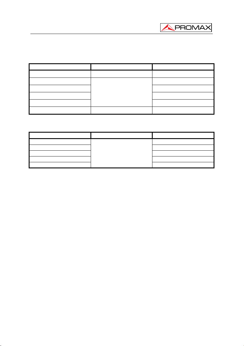
Resistance
Range Accuracy Resolution
400.0 Ω ± 1% ± 3 digits 0.1 Ω
4.000k Ω 1 Ω
40.00k Ω 10 Ω
400.0k Ω 100 Ω
4.000M Ω
40.00M Ω ± 1.5% ± 3 digits 10 KΩ
± 1% ± 1 digit
1 KΩ
Capacitance
Range Accuracy Resolution
51.20 nF 10pF
512.0 nF 100pF
5.120 uF 1nF
51.20 uF 10nF
100 uF
± 3% ± 3 digits
100nF
Diode
Voltage reading: 0 V ~ 1.5 V
On-off Test
You can a beep sound when the on-resistance is less than 50Ω.
02-2010 Page 6
Page 11

USER’S MANUAL. OS-782
2 SAFETY RULES
2.1 General
* Only use this equipment as OSCILLOSCOPE in systems with their negative of
measurement connected to no-dangerous voltages with respect to the ground
potential.
* Only use the equipment as MULTIMETER in points with a maximum potential of
400 V with respect to the ground potential and over voltage category CAT II.
* This equipment can be used in Overvoltage Category II installations and Pollution
Degree 2 environments.
The adapter of net can be used only in interiors.
* When using some of the following accessories use only the specified ones to
ensure safety
Power adapter.
Test leads (Multimeter)
Measurement probes (Oscilloscope)
* The negative of measurement like Osciloscope is common to the negative
potential of the conector of input / output of information.
* El negative of measurement of the channels of the osciloscopio is common.
* On having effected measurements to disconnect the cables that are not in use.
* Revise the condition of test leads before the utilization.
* Observe all specified ratings both of supply and measurement.
* Remember that voltages higher than 70 V DC or 33 V AC rms are dangerous.
* Use this instrument under the specified environmental conditions.
* The user not authorized to carry out the following maintenance operations.
Any change on the equipment should be carrier out byqualified personnel.
* Do not obstruct the ventilation system.
* Follow the cleaning instructions described in the Maintenance paragraph.
English
Page 7 02-2010
Page 12
USER’S MANUAL. OS-782
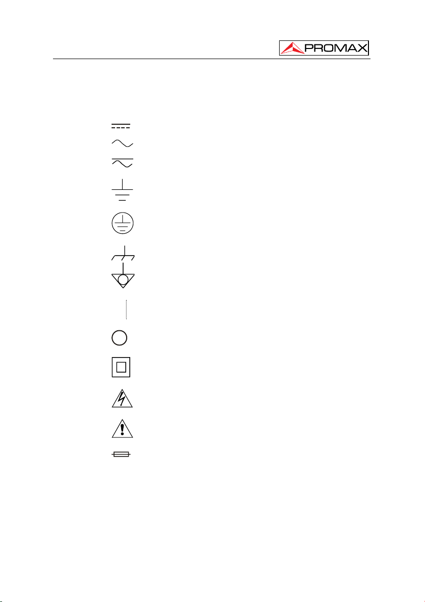
* Symbols related with safety:
DIRECT CURRENT
ALTERNATING CURRENT
DIRECT AND ALTERNATING
(Class II Protection)
(Risk of electric shock)
GROUND TERMINAL
PROTECTIVE CONDUCTOR
FRAME TERMINAL
EQUIPOTENTIALITY
ON (Supply)
OFF (Supply)
DOUBLE INSULATION
CAUTION
CAUTION REFER TO MANUAL
FUSE
02-2010 Page 8
Page 13

USER’S MANUAL. OS-782
2.2 Descriptive Examples of Over-Voltage Categories
Cat I Low voltage installations isolated from the mains
Cat II Portable domestic installations
Cat III Fixed domestic installations
Cat IV Industrial installations
English
Page 9 02-2010
Page 14

USER’S MANUAL. OS-782
02-2010 Page 10
Page 15
USER’S MANUAL. OS-782
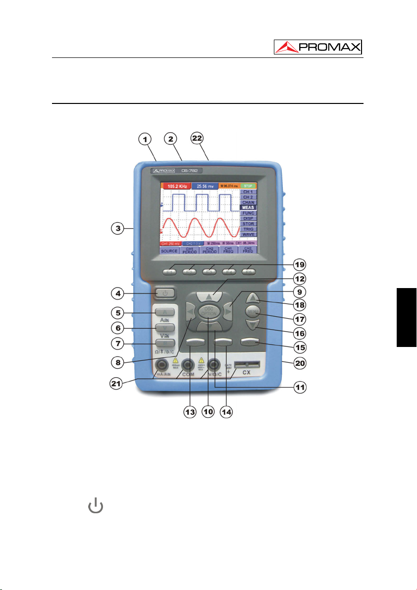
3 DESCRIPTION FOR FRONT PANEL AND KEYS
See the following Figure 1 :
English
Description:
1. Power adapter jack.
2. USB port.
3. Backlight switch.
4.
5. A: Multimeter current measurement key.
Page 11 02-2010
: Power switch.
Figure 1.- Front Pannel.
Page 16

USER’S MANUAL. OS-782
6. V: Multimeter voltage measurement key.
7. R: Multimeter resistance, triode, On/Off and capacitance measurement key.
8. OSC ◄: Oscilloscope left-direction adjustment key.
9. OSC ►: Oscilloscope right-direction adjustment key.
10. OSC OPTION: Oscilloscope setting key.
With the combination application of the four keys “OSC ◄”, “OSC ►”, “OSC
▲” y “OSC ▼”, the users can make the following settings circularly by
pressing OSC OPTION. The settings include: Voltage Unit Scale of Channel 1
(CH1 VOL); Voltage Unit Scale of Channel 2 (CH2 VOL); Primary Timebase
(TIME BASE), zero point position of channel 1(CH1 ZERO), zero point
position of channel 2(CH2 ZERO), trigger horizontal position (TIME) and
trigger level position (TRIG).
• When performing Waveform Calculation, the users can also adjust and
calculate the Display Multiplying Factor of waveform (CHM VOL) and
the vertical display position (CHM ZERO).
• In cursor measurement mode, the users can adjust the positions of
Cursor 1 (V1 or T1) and Cursor 2 (V2 or T2).
11. OSC ▼: Oscilloscope display downward adjustment key.
12. OSC ▲: Oscilloscope display upward adjustment key.
13. OSC/DMM: Operation mode switching key between oscilloscope and
multimeter.
14. AUTOSET: Oscilloscope “AUTOSET” setting key.
• Under the Multimeter Mode, when performing the current or voltage
measurement, you can make a measurement switch between AC and
DC with this key pressed; when performing the resistance
measurement, you can select resistance, diode, On/Off or capacitance
measurement circularly with this key.
• While this key is used for auto setting under the oscilloscope operation
mode.
15. RUN/STOP: key for running or stopping the operation.
16. MENU ▼: Choose the lower item on the menu list.
17. MENU: Show / Hide the menu.
18. MENU ▲: Choose the upper item on the menu list.
19. F1~F5: Switch or Adjust options for each menu.
20. BCN input connectors for oscilloscope channels: CH1 and CH2.
21. Multimeter input terminals: Three
terminals banana-type; Ma/A, COM, V/Ω/C
and two socket terminals for capacitance measurement.
22. Probe compensation output. Test signal of 5 Vpp and 1 kHz frequency.
02-2010 Page 12
Page 17
USER’S MANUAL. OS-782
4 USING THE OSCILLOSCOPE
4.1 Power-Up the oscilloscope
Connect oscilloscope to AC power via a power adapter as shown in Figure 1.
(The oscilloscope may still work with built-in Li-ion battery even without AC power
supply).
Turn the oscilloscope on by pressing down the power on/off key “
The instrument then performs Selfchecking after power on. A greeting window
and a sentence “press any key to continue” will display on the screen when the system
finishes selfchecking.
The users can press any key to enter the measuring function.
The oscilloscope is powered up in its last setup configuration.
“.
4.2 Charging the oscilloscope
The lithium battery is possibly not charged when delivery. To make the battery
with enough electric quantity, it must be charged for 4 hours (the test tool must be
turned off during charging). The battery can supply power for 4 hours after being
charged completely.
When supplying power by using the battery, a battery indicator is displayed on the
top of the screen to show the consumption condition of electric quantity. The symbols
that are possibly appear include
only be used for about 5 minutes. To charge the battery and power the instrument,
connect the oscilloscope using a power adapter according to Figure 1 to charge the
battery. The charging speed can be increased by turning off the test tool.
To avoid superheat of battery during charging, the environment temperature is
NOTE
not allowed to exceed the permissible value given in technical specification.
NOTE:
No hazard will occur even connecting the charger for a long time, e.g. during a
whole weekend. The instrument can automatically switch to slowly charging
status.
, , and , where shows that the battery can
English
Page 13 02-2010
Page 18
USER’S MANUAL. OS-782
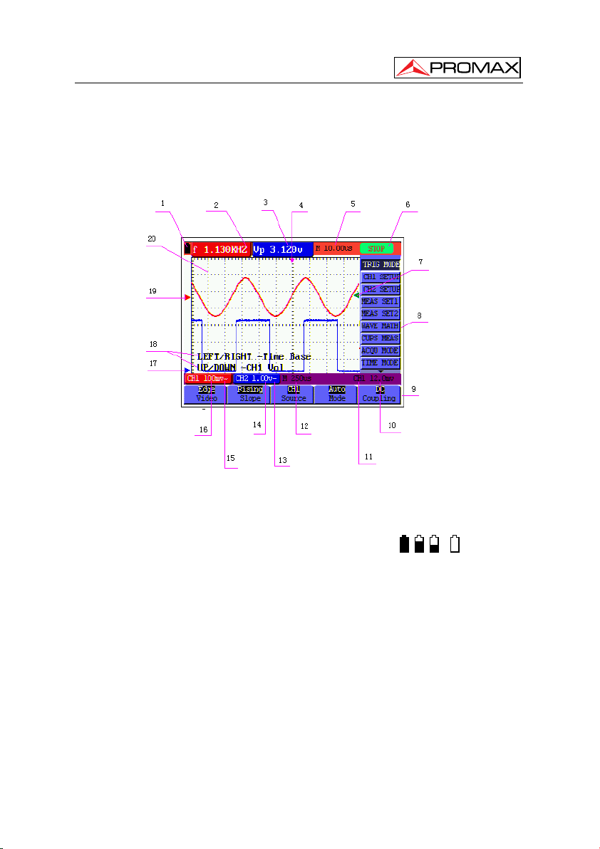
4.3 Oscilloscope Operation Window
See the following figure 2 :
Figure 2.- Oscilloscope Operation Window.
Description
1. Battery electric quantity indicating symbols, including:
, , y .
2,3 Measurement indicators 1 and 2. Diverse parameters can be shown:
Frequency “f”, peak value (Up), V (average value) etc…
Two parameters from one channel or one parameter from each channel can
be shown.
4. The pointer indicates the horizontal triggering position.
02-2010 Page 14
Page 19

USER’S MANUAL. OS-782
5. This reading gives the Time Difference between the horizontal triggering
6. The trigger state indicates the following information.
position and the screen centerline. It reads zero when the pointer is in the
center of the screen.
Auto: The oscilloscope is working in the automatic mode and displaying
the waveform under the non-trigger state.
Trig’d: The oscilloscope has detected a trigger and collecting the
information generated after the trigger.
Ready: All pre-triggered data have been captured and the oscilloscope has
been ready to receive trigger signals.
Scan: The oscilloscope can gather and display the waveform data
continuously in scanning mode.
Stop: The oscilloscope has stopped collecting the waveform data.
7. The green pointer shows the trigger voltage level.
8. Oscilloscope main menu. Pressing the “MENU button this menu will be
visualised/hide.
9. Menu setting options: There are different setting options for different menus.
10. It reads the value of trigger voltage level.
11. The display shows the trigger signal source.
12. The reading gives the value of primary time base.
13. These graphics present the coupling modes of channel CH2. The graphic “∼”
indicates AC, the graphic “—” indicates DC.
14. It shows the vertical V/div value for channel CH2.
15. These graphics show the coupling mode of CH1, among which the graphic “∼”
express indicates AC, the graphic “—” indicates DC.
16. It shows the vertical V/div value for channel CH1.
17. The blue indicator shows the CH2 zero position. If channel CH2 is
deactivated, this indicator disappears
English
Page 15 02-2010
Page 20
USER’S MANUAL. OS-782
18. OSC OPTION indications: Whenever you press the OSC OPTION they are
shown parameters to be modified by means of the cursor keys: W, X, S and
T.
19. The red indicator shows the CH1 zero position. If channel CH1 is deactivated,
this indicator disappears.
20. Waveform display area. Red waveform represent CH1, blue waveform
represent CH2.
4.4 Navigating a Menu
The following example shows how to use the tool’s menus to select a function, as
shown in the following figure.
1. Press the MENU key to show the Functions Menu in the right side of the display
and the corresponding parameters or options in the lower part of the display. In
order to hide the Functions Menu press the MENU key again.
2. Press the MENU S or MENU T key to select different function menus.
3. Press a key from F1 to F5 to modify the diverse parameters of each function.
Figure 3.- The tool’s menus.
02-2010 Page 16
Page 21
USER’S MANUAL. OS-782
4.5 Manually Setting the Vertical System, Horizontal System and
Trigger Position
With the combination application of the four keys “OSC ◄”, “OSC ►”, “OSC ▲”
and “OSC ▼”, the users can make the following settings circularly by pressing OSC
OPTION. The settings include: Voltage Unit Scale of Channel 1 (CH1 VOL); Voltage
Unit Scale of Channel 2 (CH2 VOL); Primary Timebase (TIME BASE), zero point
position of channel 1(CH1 ZERO), zero point position of channel 2(CH2 ZERO), trigger
horizontal position (TIME) and trigger level position (TRIG).
The following example shows how to use “OSC OPTION” key to make a setting.
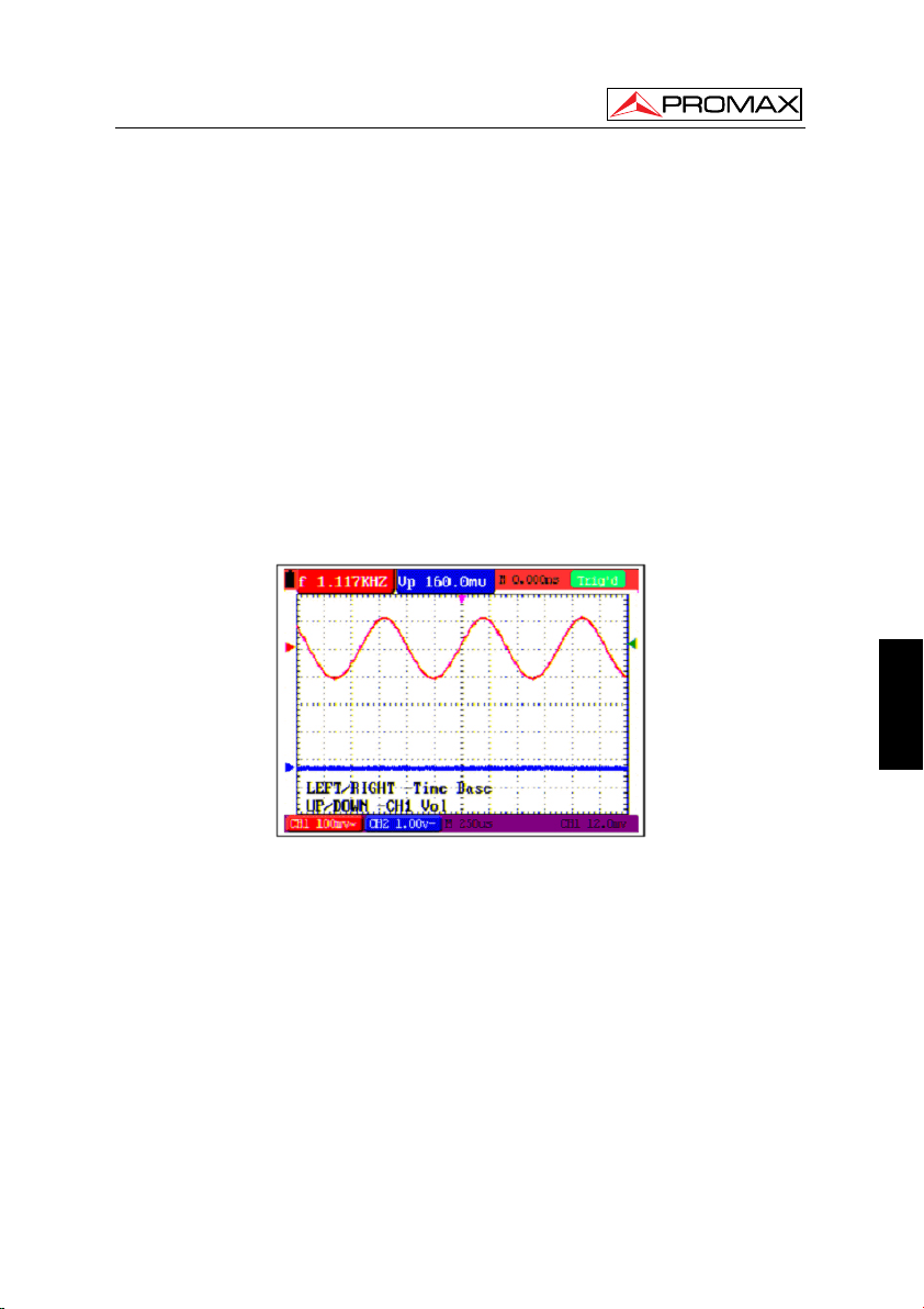
1. Press once the “OSC OPTION” key; the following is displayed at the bottom
left side of the screen, as shown in the figure below.
◄/► — Time Base
S/T — CH1 Vol
English
Figure 4.- Voltage Unit Scale of Channel 1.
2. Press the key “OSC S” or “OSC T” to adjust the vertical scale of Channel 1
and press , y “OSC ◄” “OSC ►” to adjust the horizontal time scale.
3. Press “OSC OPTION” once again, the following display is visible at bottom
left side of the screen, as shown in the following figure:
◄/► — Time Base
S/T — CH2 Vol
Page 17 02-2010
Page 22

USER’S MANUAL. OS-782
Figure 5.- Voltage Unit Scale of Channel 2.
4. Press the “OSC S” or “OSC T” key to adjust the vertical scale of Channel 2
and press the “OSC ◄” or “OSC ►” key to adjust the horizontal time scale.
5. Press the “OSC OPTION” key one more time, and the following display is
visible at the bottom left side of the screen, shown as the following figure.
◄/► — Time
S/T — CH1 Zero
Figure 6.- Zero point position of channel 1.
6. Press “OSC ▲” or “OSC ▼” key to adjust the zero position of Channel 1 in
vertical direction and press “OSC ◄” or “OSC ►” key to adjust the horizontal
position.
7. Again, press “OSC OPTION” key and the following appears at the bottom left
side of the screen, shown as the following figure 7.
02-2010 Page 18
Page 23

USER’S MANUAL. OS-782
◄/► — Time
S/T — CH2 Zero
Figure 7.- Zero point position of channel 2.
8. Press the “OSC S” or “OSC T” key to adjust the zero position of Channel 2
in the vertical direction and press “OSC ◄” or “OSC ►” key to adjust the
horizontal position.
9. Press “OSC OPTION” key once more and the following appears at the bottom
left of the screen, shown as the following figure 8.
◄/► — Time
S/T — Trig
Figure 8.- Trigger level position.
English
Page 19 02-2010
Page 24

USER’S MANUAL. OS-782
10. Press the “OSC S” or “OSC T” key to adjust the trigger position of Channel 2
and press “OSC ◄” or “OSC ►” key to adjust the horizontal position.
11. Press the “OSC OPTION” key again and return back to step 1.
4.6 Resetting the Oscilloscope
If you want to reset the Oscilloscope to the factory settings, do the following:
1. Press “MENU” key and the function menu appears on the right side of the
screen.
2. Press the “MENU S” or “MENU T” key to select function setting and three
options are visible at the bottom of the screen.
3. Press “F1” RESET key to select the factory settings. The oscilloscope is set
to be the factory settings.
See the following figure 9.
Figure 9.- Reset the Oscilloscope.
4.7 Displaying an Unknown Signal with Auto Set
The Auto-Set feature lets the Oscilloscope display and measure unknown signals
automatically. This function optimizes the position, range, time base, and triggering and
assures a stable display of virtually any waveform. This feature is especially useful for
quickly checking several signals.
02-2010 Page 20
Page 25

USER’S MANUAL. OS-782
To enable the Auto-Set feature, do the following:
1. Connect the test probe to the tested signals.
2. Press the AUTO SET key and the Oscilloscope is under the automatic
measurement condition. The tested signals appear on the screen.
4.8 Automatic zero-returning of trigger horizontal position and trigger
level position
When we adjust the trigger horizontal position and trigger level position to be
maximal to make it off the screen center remotely, then we perform the following steps
to make trigger horizontal position and trigger level position return to zero automatically.
1. Press “OSC ◄” key and “OSC ►” key simultaneously, the trigger horizontal
position automatically returns to zero.
2. Press “OSC S” and “OSC T” button simultaneously, the trigger level position
automatically returns to zero.
4.9 Automatic Measurements
The Oscilloscope offers 20 ranges of automatic scope measurements. Your can
display two numeric readings: measurement 1 and measurement 2. These measures
are shown in the left upper part of the display and can be shown two parameters of a
same channel or a parameter of each channel.
To choose a frequency for CHI1, do the following:
1. Press MENU, key and the function menu appears on the right side of the
screen.
2. Press “MENU S” or “MENU T” key to select measurement 1. Five items
selectable are visible at the bottom of the screen.
3. Press F1 key and select Freq CH1 from the mean square root value item.
The measurement 1 window turns its color into red and shows the frequency
for input CHI.
NOTE: When pressing the F1∼F5 keys the measured channel CH1/CH2 changes
alternatively.
English
Page 21 02-2010
Page 26

USER’S MANUAL. OS-782
To choose a Peak-Peak measurement for Input CH2, do the following:
1. Press MENU, key and the function menu is displayed on the right side of the
screen.
2. Press “MENU S” or “MENU T” key and select Measurement 2, with 5 items
selectable displayed at the bottom of the screen.
3. Press F4 key to select PK-PK CH2 from Peak-Peak item. The measurement
2 window turns its color to be blue and shows the peak-peak value for input
CH2. (See the following figure 10).
NOTE: When pressing the F1∼F5 keys the measured channel CH1/CH2 changes
alternatively.
Figure 10: Automatic scope measurements.
4.10 Freezing the Screen
You can freeze the screen (all readings and waveforms):
1. Press the RUN/STOP key to freeze the screen and STOP appears at top right
02-2010 Page 22
side of the screen.
2. Press the RUN/STOP key once more to resume your measurement. (See the
following figure 11).
Page 27

USER’S MANUAL. OS-782
Figure 11.- Freezing the screen.
4.11 Setting the Vertical CH1 and CH2
Each channel has its own independent vertical menu and each item can be set
respectively based on the specific channel.
Open the vertical menu of functions and select to CHANNEL 1 or CHANNEL 2
functions. The parameters to be modified with F1∼F5 keys appear in the lower part of
the display.
English
Page 23 02-2010
Figure 12.- Setting the Vertical CH1 and CH2.
Page 28

USER’S MANUAL. OS-782
The following Table describes the Vertical Channel menu:
Function
menu
Setting
Coupling AC
DC
Description
The DC component in the input signal is blocked.
The AC and dc components of the input signal are
allowed.
Ground
Channel Close
Open
Probe 1x
10x
Close the channel.
Open a channel.
Select one according the probe attenuation factor to
ensure a correct vertical scale reading.
100x
1000x
Invert Close
Open
Waveform is displayed normally.
Open the Invert function of the waveform setting.
4.11.1 Setting the Channel Coupling
With CH1 taken for example, the measured signal is a sine wave signal
containing a dc offset. Press F1 Coupling first and then AC to make an ac coupling
setting. The dc component contained in the tested signal is blocked.
Press F1 Coupling first and then DC to make a dc coupling setting. Both dc and
ac components contained in the tested signal are permitted. The waveform is displayed
as the following figure 13, figure 14.
Figure 13.- AC coupling.
02-2010 Page 24
Page 29

USER’S MANUAL. OS-782
Figure 14.- DC coupling.
4.11.2 Make Open and Close Settings on Channel
With CH1 taken for example:
Press F2 Channel first, then Close to make a Close setting on CH1.
Press F2 Channel key first, then Open to make an Open setting on CH1.
4.11.3 Adjusting the Probe Scale
It is necessary to adjust the probe attenuation scale factor correspondingly in the
channel operation menu in order to comply with the probe attenuation scale. If it is a
10:1 probe, the scale of the input channel of the oscilloscope should be selected as 10X
to avoid any error occurring in the displayed scale factor information and tested data.
Press F3 Probe to jump to the relative probe:
Probe attenuation factor Corresponding Menu Setting
1:1 1x
10:1 10x
100:1 100x
1000:1 1000x
Table.- Probe attenuation factor and the corresponding menu setting
English
Page 25 02-2010
Page 30

USER’S MANUAL. OS-782
4.11.4 Setting of Inverted Waveform
Inverted waveform: The displayed signal reverses 180 degrees relatively to the
ground potential.
Press F4 Invert to start Invert; again press F4 Invert to close Invert.
4.12 MATH function “MATH”
The MATH functions in showing the result of adding, subtracting, multiplying or
dividing calculation on CH1 and CH2 channel waveforms. Also, the result of arithmetic
operation can be measured with grid or cursor. The amplitude of the calculated
waveform can be adjusted with CHM VOL, which is displayed in the scale factor form.
The amplitude ranges from 0.001 through 10 and steps in the 1-2-5 form, that is, it can
be expressed as 0.001X, 0.002X, 0.005X, 10X. The position of the calculated waveform
can be adjusted up and down with the CHM ZORE key used.
The corresponding operation function table.
Setting Description
CH1-CH2
CH2-CH1
CH1+CH2
CH1*CH2
CH1/CH2
To perform the CH1+CH2 waveform calculation, do the following:
1. Press the MENU key and the function menu appears at the right of the
screen.
2. Press the “MENU V” or “MENU W” key to select MATH and 5 options are
displayed at the bottom of the screen.
3. Press the F3 CH1 + CH2 key and the obtained waveform M appears on the
screen. Again, press the F3 key and Close the waveform M.
4. Press the OSD OPTION key and the following is displayed on the screen:
5. Press the “OSC V” or “OSC W” key to adjust the amplitude of the waveform
M.
CH1 waveform minus CH2 waveform.
CH1 waveform minus CH2 waveform.
Add CH1 waveform into CH2 waveform.
Multiply CH1 waveform and CH2 waveform.
Divide CH1 waveform by CH2 waveform.
/► - Time Base
◄
/W - CH1 Vol
V
02-2010 Page 26
Page 31

USER’S MANUAL. OS-782
6. Again, press the OSD OPTION key twice and the screen shows the following:
/► Time
◄
V
7. Press the “OSC V” or “OSC W” key to adjust the position of the waveform
Math. Now, look at the display and you will find a screen that looks like the
following Figure 15.
/W - CHM Zero
Figure 15.- Waveform mathematics.
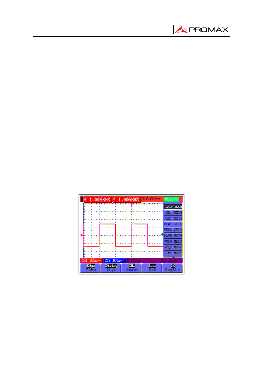
4.13 Setting the Trigger System. TRIGGER Function.
The Trigger defines the time when the acquisition of data and display of
waveform start. If it is set correctly, the trigger can turn an unstable display into a
significant waveform.
When starting the acquisition of data, the oscilloscope collects sufficient data to
draw the waveform at the left side of the triggering point. With waiting for the triggering
condition, the oscilloscope is gathering data continuously. After a trigger is detected, the
oscilloscope gathers enough data continuously to draw the waveform at the right side of
the triggering point.
To make a trigger mode setting, do the following:
1. Press the MENU key and the function menu appears at the right of the
screen.
2. Press the “MENU V” or “MENU W” key to select TRIG MODE and five items
selectable are displayed at the bottom of the screen.
English
Page 27 02-2010
Page 32

USER’S MANUAL. OS-782
3. Select and press one from F1 through F5 key to make a different setting.
4. Press the OSD OPTION key and the following is shown on the screen:
/► — Time
◄
V
5. Press the “OSC V” or “OSC W” key to adjust the trigger level position. Now,
look at the display: you can see a screen in the following figure 16.
/W — Trig
Figure 16.- Edge triggering.
4.14 Triggering Control
There are two triggering modes including Edge triggering and Video triggering.
Each trigger mode is set by different function menu.
Edge triggering: It occurs when the trigger input passes through a given level
along the specified direction.
Video triggering: Perform video field trigger or line trigger on the standard video
signals.
02-2010 Page 28
Page 33

USER’S MANUAL. OS-782
4.14.1 Edge triggering
The Edge triggering menu is described in the following table.
Function menu Settings Description
Slope Rise
Signal source CH1
1/2
Fall
CH2
Triggering on the rise edge of the
signal.
Triggering on the fall edge of the
signal.
CH1 is used as the trigger source.
CH2 is used as the trigger source.
To next menu.
2/2
Back to previous menu.
Bloqueo
Trigger mode Auto
Normal
Single shot
Coupling AC
DC
HF Suppression
LF Suppression
Term interpretation
Trigger modes: There are three kinds of trigger modes available for this
oscilloscope, that is, auto, normal and single shot.
To holdoff menu.
Acquisition of waveforms is
possible even if there is no
triggering condition detected.
Acquisition of waveforms can only
be done when the triggering
condition is satisfied.
The sampling is performed on a
waveform when one trigger is
detected, then stop sampling.
With this mode selected, the DC
component is prevented from
passing-though.
All dc components are allowed.
The HF part of the signal is
prohibited and only the HF
component is allowed.
The LF part of the signal is
prohibited and only the LF
component is allowed.
English
Page 29 02-2010
Page 34

USER’S MANUAL. OS-782
1. Automatic
trigger mode: The oscilloscope can acquire the waveform without any
triggering condition detected in this mode, in which it will be
triggered compulsively when waiting for a specified period of
time without any triggering condition ignited When an invalid
trigger is enforced the oscilloscope can not keep the
waveform in phase.
2. Normal trigger
mode: In this mode, the oscilloscope cannot acquire the waveform
till it is triggered. When there is not any trigger, the
oscilloscope will display the origin waveform without new
waveforms captured.
3. Single shot
mode: In this mode, the oscilloscope will detect a trigger and capture
a waveform at each time when the customer presses the
RUN/STOP key.
4.14.2 Video triggering
With Video triggering selected, the oscilloscope performs the NTSC, PAL or
SECAM standard video signals field, line trigger, odd field, even field or line num
trigger. Now, you can see a screen that looks like the following figure 17, figure 18.
Figure 17: Video field trigger.
02-2010 Page 30
Page 35

USER’S MANUAL. OS-782
The Video triggering menu is described in the following table:
Function
menu
Settings Description
Polarity Normal
Invert
Figure 18.- Video line trigger.
Applicable to the video signal in which the black level
is of low level.
Applicable to the video signal of which the black level
is of high level.
Signal
source
CH1
CH2
Sync Line
Field
Odd Field
Even field
Line NO
1/2
Select CH1 as the trigger source.
Select CH2 as the trigger source.
Make a video line trigger synchronization setting.
Make a video field trigger synchronization setting.
Make a video odd field trigger synchronization setting.
Make a video even field trigger synchronization
setting.
Make a video designed line.
To next menu.
The Video triggering menu (Second page):
1. When the sync is Line, Field, Odd Field, Even Field, the second page menu is
shown as below.
Format
Holdoff
2/2
NTSC
PAL/SECAM
Video format setting
To go to holdoff menu
Back to previous menu.
English
Page 31 02-2010
Page 36

USER’S MANUAL. OS-782
2. When the sync is Designed Line,the second page menu is shown as below.
Format
Line
Line No.
Holdoff
2/2
NTSC
PAL/SECAM
Increase
Decrease
Set and Show the line valve
To go to holdoff menu
Video format setting
Set the line value to increase
Set the line value to decrease
Back to previous menu.
When you go to the holdoff menu,you can see a screen in the following figure 19.
Figure19.-Trigger Holdoff.
The Holdoff menu is described in the following table:
Function menu Settings Description
Off Time
Time
Reset
Off Time
Back
Set time slot before another trigger event.
Increase
Decrease
Set the off time to increase
Set the off time to decrease.
Reset Holdoff time to 100ns.
Back to previous menu.
02-2010 Page 32
Page 37

USER’S MANUAL. OS-782
NOTE: Trigger Holdoff can stabilize complex waveform, such as the pulse
range. Holdoff time is the oscilloscope’s waiting period before starting a
new trigger. During Holdoff, oscilloscope will not trigger until Holdoff
ends.
4.15 Acquiring Mode Setting
Open the vertical menu of functions and select the ACQUIRE function. The
parameters to be modified with F1∼F5 keys will appear in the lower part of the display.
The Acquiring Mode menu is described in the list shown as below:
Function
menu
Sampling
Peak
detection
Average
value
Average
factor
Settings Description
Normal sampling mode.
Used to detect the jamming glitch and reduce the possible
Used to reduce the random and unrelated noises. Several
4, 16, 64 o
128
blurring.
average factors are available for being selected.
Select the average factor.
4.16 Display Setting
Open the vertical menu of functions and select the DISPLAY function. The
parameters to be modified with F1∼F5 keys will appear in the lower part of the display.
The Display Setting menu is described in the following table:
Function menu Settings Description
Type Vector
Dot
Persistence Close
1s
2s
5s
Infinite
Display format YT
XY
Communication Bitmap
Vector
The vector is filled up spaces between neighboring
sampling points in the display.
Only sampling points are displayed.
Setting persistence time for each sampling point.
Display the relative relationship between vertical
voltage and horizontal time. Display CH1 on the
horizontal axis and CH2 on the vertical axis.
The data transmitted in communication are bitmaps.
The data transmitted in communication are vectors.
English
Page 33 02-2010
Page 38

USER’S MANUAL. OS-782
4.16.1 Display Style
The display style includes Vector and Dot displays, shown as the following figure
20, figure 21:
Figure 20.- Dot style.
Figure 21.- Vector style.
4.16.2 Persistence
With Persistence function selected, the displayed saved original data gradually
decay in color and the new data are bright in color; with infinite persistence mode
selected, the recorded points will be kept on the screen till the controlled value is
changed.
02-2010 Page 34
Page 39

USER’S MANUAL. OS-782
4.16.3 XY mode
This mode is only applicable to CH1 and CH2. With the XY mode selected, CH1
is displayed on the horizontal axis and CH2 is on the vertical axis; when the
oscilloscope is under the sampling mode in which no trigger is found, the data appear in
light spots.
Operations for various control keys are shown as below:
The following functions do not work in the XY display mode:
• The CH1 VOL and CH1 ZORE for CH1 are used to set the horizontal
scale and position.
• The CH2 VOL and CH2 ZORE for CH2 are used to set the vertical
scale and position continuously.
• Reference or digital value waveform.
• Cursor.
• Auto Setting.
• Time base control.
• Trigger control.
4.17 Waveform Saving Setups
The oscilloscope can save 4 waveforms, which can be displayed on the screen
with the present waveform. The recalled waveform saved in the memory cannot be
adjusted.
The waveform saving /recalling menu is described in the following list:
Function menu Setups Description
Signal source
Wave
Saving
Addresses A, B,
C, D
CH1
CH2
MATH
A, B, C, D Select the address for saving or recalling a
Store the waveform of a selected signal source into
Close
Start
Select the displayed waveform which you want to
save.
waveform.
the selected address.
Close or start displaying the waveforms stored in
address A, B, C or D.
English
Page 35 02-2010
Page 40

USER’S MANUAL. OS-782
To save a waveform on CH1 in address A, do the following:
1. Press the MENU key and the function menu appears at the right of the
screen.
2. Press the “MENU ▲” or “MENU ▼” key to select the Waveform Saving. Four
items selectable are displayed at the bottom of the screen.
3. Press the F1 key to select the signal source CH1.
4. Press the F2 key to select the address A.
5. Press the F3 key to save the waveform on CH1 in address A.
To display the saved waveform on the screen, do the following:
6. Press the F4 key to select Start for the address A. The waveform saved in
address A will be displayed on the screen in green color.
The display color is green, and the zero point of waveform k, voltage and time is
purple.
Now, you can see a screen that looks like the following figure 22.
Figure 22.- Waveform Saving.
4.18 Function Setting Menu
Open the vertical menu of functions and select the SYSTEM function. The
parameters to be modified with F1∼F5 keys will appear in the lower part of the display.
The function setting menu is described in the following list:
02-2010 Page 36
Page 41

USER’S MANUAL. OS-782
Function menu Setting Description
Recall Factory
Auto Calibration
Language
Self-correcting
The self-correcting program can improve the accuracy of the oscilloscope under
the ambient temperature to the maximum. If the ambient temperature variation is equal
to or larger than 5 Celsius degrees, the self-correcting program should be performed to
gain the maximum accuracy.
Before the self-correcting program is performed, the probe or lead should be
disconnected with the input connector, then, select the F2 key “Self-correcting“ item.
After confirming that everything is ready, press the F2 key “Self-correcting” key and
enter into the self-correcting program.
Resume the instrument to its factory settings.
Perform the self-correcting procedure.
SPANISH
ENGLISH
Select the display language of the system.
4.19 Making Automatic Measurements
The oscilloscope can perform 20 types automatic measurements such as
frequency, cycle, average value, peak-to-peak value , root mean square value, Vmax,
Vmin, Vtop, Vbase, Vamp, Overshoot, Preshoot, RiseTime, Fall Time, +Width, -Width,
+Duty, -Duty, Delay A
measurement results simultaneously on the screen.
The function menu for automatic measurements is described in the following list.
B and Delay A B . And gives two kinds of
English
Function menu Settings Description
Freq
Period
Mean
Peak-Peak
Cyc RMS
Vmax
Vmin
Page 37 02-2010
CH1
CH2
CH1
CH2
CH1
CH2
CH1
CH2
CH1
CH2
CH1
CH2
CH1
CH2
Measure the frequency of CH1
Measure the frequency of CH2
Measure the Period of CH1.
Measure the Period of CH2
Measure the average value of CHI.
Measure the average value of CH2.
Measure the peak-to-peak value of CH1.
Measure the peak-to-peak value of CH2.
Measure root mean square (RMS) value of CH1.
Measure root mean square (RMS) value of CH2.
Measure the Vmax of CH1
Measure the Vmax of CH2
Measure the Vmin of CH1
Measure the Vmin of CH2
Page 42

USER’S MANUAL. OS-782
Function menu Settings Description
Vtop
Vbase
Vamp
Overshoot
Preshoot
Rise Time
Fall Time
+Width
-Width
+Duty
-Duty
DelayA B
DelayA B
To measure the frequency of CH1 with Measurement 1 and the peak-to-peak of
CH2 with Measurement 2, do the following:
1. Press the MENU key and the function menu is shown at the right of the screen.
CH1
CH2
CH1
CH2
CH1
CH2
CH1
CH2
CH1
CH2
CH1
CH2
CH1
CH2
CH1
CH2
CH1
CH2
CH1
CH2
CH1
CH2
CH1
CH2
CH1
CH2
Measure the Vtop of CH1
Measure the Vtop of CH2
Measure the Vbase of CH1
Measure the Vbase of CH2
Measure the Vamp of CH1
Measure the Vamp of CH2
Measure the Overshoot of CH1
Measure the Overshoot of CH2
Measure the Preshoot of CH1
Measure the Preshoot of CH2
Measure the RiseTime of CH1
Measure the RiseTime of CH2
Measure the Fall Time of CH1
Measure the Fall Time of CH2
Measure the +Width of CH1
Measure the +Width of CH2
Measure the -Width of CH1
Measure the -Width of CH2
Measure the +Duty of CH1
Measure the +Duty of CH2
Measure the -Duty of CH1
Measure the -Duty of CH2
Measure the DelayA
Measure the DelayA
Measure the DelayA
Measure the DelayA
B of CH1
B of CH2
B of CH1
B of CH2
2. Press the MENU
appear at the bottom of the screen.
3. Press the F1 key to select the frequency measurement as CH1. The
measurement window 1 on the screen turns into one red in color and shows the
frequency of CH1.
4. Press the MENU
appear at the bottom of the screen.
5. Press the F4 key to jump to the peak-to-peak measurement as CH2. The
measurement window on the screen turns into one blue in color and shows the
peak-to-peak value of CH2.
02-2010 Page 38
V or MENU W key to select Measurement 1. Five options
V or MENU W key to select Measurement 2. Five options
Page 43

USER’S MANUAL. OS-782
Now, you can see a screen that looks like the following figure.
Figure 23.- Automatic Measurements.
Term interpretation
Vpp: Peak-to-Peak Voltage.
Vmax: The maximum amplitude. The most positive peak voltage measured
over the entire waveform.
Vmin: The minimum amplitude. The most negative peak voltage
measured over the entire waveform.
Vamp: Voltage between Vtop and Vbase of a waveform.
Vtop: Voltage of the waveform’s flat top, useful for square/pulse
waveforms.
Vbase: Voltage of the waveform’s flat base, useful for square/pulse
waveforms.
Overshoot: Defined as (Vmax-Vtop)/Vamp, useful for square and pulse
waveforms.
Preshoot: Defined as (Vmin-Vbase)/Vamp, useful for square and pulse
waveforms.
Average: The arithmetic mean over the entire waveform.
Vrms: The true Root Mean Square voltage over the entire waveform.
Rise Time: Time that the leading edge of the first pulse in the waveform takes
to rise from 10% to 90% of its amplitude.
Fall Time: Time that the falling edge of the first pulse in the waveform takes to
fall from 90% to 10% of its amplitude.
English
Page 39 02-2010
Page 44

USER’S MANUAL. OS-782
+Width: The width of the first positive pulse in 50% amplitude points.
-Width: The width of the first negative pulse in the 50% amplitude points.
Delay 1→2
Delay 1→2
+Duty: +Duty Cycle, defined as +Width/Period.
-Duty: -Duty Cycle, defined as -Width/Period.
: The delay between the two channels at the rising edge.
: The delay between the two channels at the falling edge.
4.20 Setting the Cursor Measurements
This oscilloscope allows you to make manual cursor measurements on time and
voltage. The signal sources include Channel 1(CH1) and Channel 2 (CH2).
The cursor measurement menus are listed and described in the following table:
Function
menus
Type Close
Signal
sources
To make a voltage measurement on CH1, doing the following:
1. Press the MENU key and the function menus are displayed at the right of the
2. Press the “MENU ▲” or “MENU ▼” key to select Cursor Measurement. Two
3. Press F1 key to select the measurement type Voltage. Two purple crossing
4. Press the F2 key to select the measured channel CH1.
Settings Description
Close the cursor measurement.
Voltage
Time
CH1,
CH2
screen.
options are shown at the bottom of the screen.
dashed lines V1 and V2 are shown on the screen.
Display the voltage measurement cursor and menu.
Display the time measurement cursor and menu.
Select the waveform channel on which the cursor
measurement will be performed.
5. Press and hold the OSC OPTION key till the
the screen. At this time, adjust OSC ▲
dashed line V1 is moving up and down while the measured voltage value of
V1 relative to the zero position of CH1 appears on the screen.
02-2010 Page 40
▲/▼ CURSOR V1 is visible on
or OSC ▼ and you can see that the
Page 45

USER’S MANUAL. OS-782
6. Press and hold the OSC OPTION key till ▲
screen. Now, adjust the OSC ▲ or OSC ▼ and you can observe the dashed
line V2 moving up and down while the measured voltage value of V2 relative
to the zero position of CH1 is displayed on the screen. Also, the absolute
values of V1 and V2 can be shown on the screen.
Figure 24: Use the cursor for a voltage measurement.
To use the cursor for a time measurement on CH1, do the following:
1. Press the MENU key and the function menus are displayed at the right of the
screen.
2. Press the “MENU ▲” or “MENU ▼” key to select Cursor measurement key.
Two key labels selectable are shown at the bottom of the screen.
3. Press the F1 key to the measurement type Time. Two vertical dashed lines
T1 and T2 appear on the screen.
4. Press the F2 key and jump to the measured channel CH1.
5.- Press and hold the OSC OPTION key till the ▲/▼ CURSOR T1 appears on
the screen. Then, adjust the OSC ▲ or OSC ▼ and you can observe the
dashed line moving left and right. At the same time, the time value of T1
relative to the screen middle point position will be displayed on the screen.
6.- Keep pressing on the OSC OPTION key till the ▲/▼ CURSOR T2 is
displayed on the screen. Then, adjust the OSC ▲ or OSC ▼ and you can find
that the dashed line T2 is moving right and left while the time value of T1
relative to the screen middle point position appears on the screen. You can
also observe the absolute time values and frequencies of T1 and T2. Now,
you can see a screen that looks like the following figure 25.
/▼ CURSOR V2 appears on the
English
Page 41 02-2010
Page 46

USER’S MANUAL. OS-782
Figure 25: Use the cursor for a time measurement.
4.21 Autoscale
The function is applied to follow-up signals automatically even if the signals
change at any time. Autoscale enables the instrument to set up trigger mode, voltage
division and time scale automatically according to the type, amplitude and frequency of
the signals.
The menu is as follows:
Function menus Settings Description
Autoscale OFF
ON
Mode Vertical
Horizontal
HORI-VERT
Turn off Autoscale.
Turn on Autoscale.
Follow-up and adjust vertical scale without
changing horizontal setting.
Follow-up and adjust horizontal scale without
changing vertical setting.
Follow-up and adjust the vertical and horizontal
settings.
Only show one or two periods.
Show Multi-period waveforms.
02-2010 Page 42
Page 47

USER’S MANUAL. OS-782
If you want to measure voltage of Channel 1, you can do as the follows:
1. Press MENU, the function menu will appear on the right of the screen.
2. Press MENU ▲ or MENU ▼ and choose Autoscale, three options will show
at the bottom of the screen.
3. Press F1 and choose ON.
4. Press F2 and choose Hori- Vert.
5. Press F3 and
displays on the screen as figure 52:
English
Figure 26.-: Autoscale Horizontal- Vertical multi-period waveforms.
Figure 27.- Autoscale Horizontal- Vertical mono-period waveform.
Page 43 02-2010
Page 48

USER’S MANUAL. OS-782
Figure 28.- Only under vertical mode multi-period waveform.
Figure 29.- Only under horizontal mode multi-period waveform.
NOTE:
1. Entering into Autoscale function and
flicker will be on the top left corner.
(flicker every 0.5 second).
2. At the mode of Autoscale, the oscilloscope can self-estimate “Trigger mode”
(Edge, Video, and Alternate) and “Type” (Edge, Video). If now, you press
“Trigger mode” or “Type”, the forbidden information will display on the screen.
3. At the mode of XY and STOP status, pressing AUTO SET to enter into
Autoscale, DSO switches to YT mode and AUTO status.
02-2010 Page 44
Page 49

USER’S MANUAL. OS-782
4. At the mode of Autoscale, DSO is always in the state of DC coupling and
AUTO triggering. In this case, the forbidden information will be showing when
making Triggering or Coupling settings.
5. At the mode of Autoscale, if adjust the vertical position, voltage division,
trigger level or time scale of CH1 or CH2, the oscilloscope will turn off
Autoscale function and if press AUTOSET again, the oscilloscope will enter
into Autoscale.
6. Turn off the submenu at the Autoscale menu, the Autoscale is off and turn on
the submenu still enters into the function.
7. When video triggering, the horizontal time scale is 50us. If one channel is
showing edge signal, the other channel is showing video one, the time scale
refers to 50us as video one as standard.
4.22 System State Menu.
The system state menu is used to display information about the present horizontal
system, vertical system, trigger system and others. The operation steps are shown as
below.
1. Press the MENU key and the function menu is displayed at the right of the
screen.
2. Press the “MENU ▲” or “MENU ▼” key to select the System State. Four
options appear at the bottom of the screen.
3. Sequentially press key F1 through F4 key and the corresponding state
information will be shown on the screen.
following figure 30 will be displayed.
The screen that looks like the
English
Page 45 02-2010
Figure 30.- System State.
Page 50

USER’S MANUAL. OS-782
4.23 Horizontal axis setting. HORIZONTAL function
Open the vertical menu of functions and select the HORIZONTAL function. The
parameters to be modified with F1∼F5 keys will appear in the lower part of the display.
The time base mode menu is explained as the following table:
Function menu Setting Explanation
Main time base
Zone Window
Window extensión
For the operation of window extension, please execute the following steps:
1. Press MENU key, display the function menu on the right side of the screen.
2. Press “MENU ▲” or “MENU ▼” key to select time base mode, display three
options at the bottom.
3. Press
4. Press OSC OPTION key, pop up TIME BASE, at this time, then press OSC
5. Press OSC OPTION, key and call OSC ◄ / OSC ► to adjust the window
6. Press F3 key, select window extension, the defined window extends into the
F2 key to select window setting.
◄/OSC ► key to adjust the time base window area defined by two cursors,
the window size will vary.
position defined by two cursors, the window position is the time difference of
the window center to main time base’s horizontal pointer.
full-screen display.
The screen that looks like the following figure 27, 28 will be displayed.
Horizontal main time base is used to wave display
Use two cursors to define a window area
Expand the defined window to full-screen display
02-2010 Page 46
Page 51

USER’S MANUAL. OS-782
Figure 31.- Window setting.
English
Figure 32.- Window extensión.
4.24 Data transmission to the PC
The oscilloscope OS-782 has an USB port that allows to transmit the data shown
and/or memorized from the instrument to the computer.
With the equipment a CD with the communication program is enclosed. In order to
install it you must follow these instructions.
1. Insert the CD in the disc drive.
Page 47 02-2010
Page 52

USER’S MANUAL. OS-782
2. Open the explorer and run the Setup.exe file and follow the installer
instructions. By default the program is installed in folder: c \ Program files \
PROMAX\OS-wave.
3. Once installed, connect the USB cable between the equipment and the PC.
Power on the instrument, the PC will automatically detect a new equipment
and request about installing the suitable driver.
4. Select the advanced method of installation and in the following screen select
the folder: USBDRIVE which there is within the directory where the program
has been installed. Press “Next” to install the driver.
5. Now you can open the HDSO Wave program to capture data using the PC.
02-2010 Page 48
Page 53

USER’S MANUAL. OS-782
5 USING THE MULTIMETER
5.1 About this chapter
This chapter provides a step-by-step introduction to the multi-meter functions of
the test tool(hereafter. The introduction gives basic examples to show how to use the
menus and perform basic operations.
5.2 Making Meter Connections
Use the three 4-mm safety banana jack inputs for the Meter functions: COM, V/Ω
mA. Two quadratic capacitance jacks: CX. See figure 1 for the connections.
5.3 Multimeter Operation Window
English
Figure 33.-
Page 49 02-2010
Page 54

USER’S MANUAL. OS-782
Description
1.- Battery electric quantity indictor.
2.- MANUAL/AUTO RANGE indictors, among which the MANUAL means
measuring range in manual operation mode and Auto refers to the measuring
range in automatic operation mode.
3.- Measurement mode indicators:
DCV: Direct voltage measurement CC.
ACV: Alternating voltage measurement CA.
DCA: Direct current measurement CC.
ACA: Alternating current measurement CA.
R: Resistance measurement.
: Diode measurement.
: On/Off measurement.
C: Capacitance measurement.
4.- The relative magnitude measurement indicator.
5.- Running state indicators, among which RUN expresses continuous update
and STOP represents the screen locking.
6.- The reference value of the relative magnitude measurement.
7.- The multiplying power of the dial indication. To multiply the reading of dial
pointer by multiplying power will get the measurement result.
8.- The mail reading of measurement.
9.- Automatic control measuring range.
10.- Absolute/ relative magnitude measuring control: The sign “||” expresses the
absolute magnitude measuring control and “∆” represents the relative
magnitude measuring control.
11.- Manual control of the measurement range.
12.- Measurement analogue range. Test lead indicates the scale of test reading,
different test modes display different colors.
02-2010 Page 50
Page 55

USER’S MANUAL. OS-782
5.4 Making Multimeter Measurements
Press DMM/OSC key, the oscilloscope will switch to the multimeter measure, the
screen will display the multimeter windows, at the same time, prompt to correctly insert
testing pen of the multimeter, at this time, then press any key to enter into multimeter
measure.
5.4.1 Measuring Resistance Values
To measure a resistance, do the following:
1. Press the R key and R appears at the top of the screen.
2. Insert the black lead into the COM banana jack input and the red lead into the
V/Ω banana jack input.
3. Connect the red and black test leads to the resistor. The resistor value
readings are shown on the screen in Ohm. Now, you can see a screen that
looks like the following figure 34.
English
5.4.2 Making a Diode Measurement.
To make a measurement on the diode, do the following:
1. Press the R key and R appears at the top of the screen.
2. Press AUTO SET key once and the following is displayed on the screen
.
Page 51 02-2010
Figure 34.- Measure resístance.
Page 56

USER’S MANUAL. OS-782
3. Insert the black lead into the COM banana jack input and the red lead into the
V/Ω banana jack input.
4. Connect the red and black leads to the resistor and the diode resistor
readings are displayed on the screen in V. Now, you can see a screen that
looks like the following Figure 35.
5.4.3 On-off test
To perform an On-off test, do the following:
1. Press the R key and R appears on the top of the screen.
2. Press the AUTO SET key three times and the following is shown on the
screen
3. Insert the black lead into the COM banana jack input and the red lead into the
V/Ω banana jack input.
4. Connect the red and black leads to the test point. If the resistance value of the
tested point is less than 50 Ω, you will hear beep sound from the test tool.
Now, you can see a screen that looks like the following Figure 36.
.
Figure 35: Diode Measurement
02-2010 Page 52
Page 57

USER’S MANUAL. OS-782
5.4.4 Making a Capacitance Measurement
To measure a capacitance, do the following:
1. Press the R key and R appears on the top of the screen
2. Press the AUTO SET key four times and C appears at the top of the screen.
3. Insert the measured capacitance into the quadratic jack and the screen shows
the capacitance reading.
NOTE: When measured value is less than 5 nF capacitance, please use small
capacitance measurer of this multimeter and use relative value measuring
mode to improve measuring precision. It will take about 30seconds if
capacitance measurement is large than 40uF. Now, you can see a screen
that looks like the following figure 36.
Figure 36.- On-off test.
English
Figure 37.- Capacitance measurement.
Page 53 02-2010
Page 58

USER’S MANUAL. OS-782
5.4.5 Making a DC voltage Measurement (VDC)
To measure a DC voltage, do the following:
1. Press the V key and DCV appears at the top of the screen.
2. Insert the black lead into the COM banana jack input and the red lead into the
V/Ω banana jack input.
3. Connect the red and black leads to the measured point and the measured
point voltage value is displayed on the screen. Now, you can see a screen
that looks like the following Figure 38.
Figure 38.- DC voltage Measurement
5.4.6 Making a AC voltage Measurement (VAC)
To measure the AC voltage, do the following:
1. Press the V key and DCV appears at the top of the screen.
2. Press the AUTO SET key and ACV appears at the top of the screen.
3. Insert the black lead into the COM banana jack input and the red lead into the
V/ / Ω banana jack input.
4. Connect the red and black leads to the measured points and the AC voltage
values of measured points will be displayed on the screen.
02-2010 Page 54
Page 59

USER’S MANUAL. OS-782
Figure 39.- AC voltage Measurement.
5.4.7 Making a DC current Measurement (AAC)
In order to carry out the measurement of current it is necessary to connect in
series the meter and the circuit under test. Make sure that the circuit is disconnected
before doing this connection.
To measure a DC current which is less than 400 mA , do the following:
1. Press the A key and DCA appears at the top of the screen. The unit on the
main reading screen is mA. mA and 20A will display on the right bottom of
screen, press F4 or F5 to switch the measurement between Ma and 20A.
400mA is acquiescently.
2. Insert the black lead into the COM banana jack input and the red lead into the
mA banana jack input.
3. Connect the red and black leads to the measured points and the DC current
values of measured points will be displayed on the screen. Look at the
display; you can see a screen that looks like the following figure 40.
English
Page 55 02-2010
Page 60

USER’S MANUAL. OS-782
Figure 40.- DC current Measurement for 400 mA.
To measure a DC current which is larger than 400 mA, do the following:
1. Press the A key and DCA appears at the top of the screen. The unit on the
main reading screen is mA.
2. Press F5 key change to 20 A measurement, he unit on the main reading
screen is A.
3. Plug current extended module in current measure jack, then plug the probe in
the module.
4. Connect the red and black leads to the measured point and the DC current
value of the measured point will be displayed on the screen.
5. Press F4 return to 400 mA measure.
Figure 41: DC current Measurement for 20A.
02-2010 Page 56
Page 61

USER’S MANUAL. OS-782
5.4.8 Making an AC Current Measurement
In order to carry out the measurement of current it is necessary to connect in
series the meter and the circuit under test. Make sure that the circuit is disconnected
before doing this connection.
To measure an AC current which is less than 400 mA, do the following:
1. Press the A key and DCA appears at the top of the screen. The unit on the
main reading screen is mA. mA and 20A will display on the right bottom of
screen, press F4 or F5 to switch the measurement between Ma and 20A.
400 mA is acquiescently.
2. Press the AUTO SET key once and ACA is visible at the top of the screen.
3. Insert the black lead into the COM banana jack input and the red lead into the
mA banana jack input.
4. Connect the red and black leads to the measured point and the AC current
value of the measured point will be displayed on the screen. Look at the
display; you can see a screen that looks like the following figure 38.
English
Figure 42.- AC current Measurement for 400 mA.
To measure an AC current which is larger than 400 mA, do the following:
1. Press the AUTO SET key once and ACA is visible at the top of the screen.
2. Press F5 to select 20A measure, the unit of main reading window is A.
3. Press the AUTO SET key once and ACA is visible at the top of the screen.
Page 57 02-2010
Page 62

USER’S MANUAL. OS-782
4. Plug current extended module in current measure jack, then plug the probe in
the module.
5. Connect the red and black leads to the measured point and the AC current
value of the measured point will be displayed on the screen.
6. Press F4 return to 400mA measure.
Figure 43.- AC current Measurement for 20A.
5.5 Freezing the Readings.
You can freeze the displayed readings at any time.
1. Press the RUN /STOP key to freeze the screen and STOP will be displayed at
the top right of the screen.
2. Again, press the RUN /STOP key, you can resume your measurement.
Look at the display; you can see a screen that looks like the following figure 40.
02-2010 Page 58
Page 63

USER’S MANUAL. OS-782
Figure 44: Freezing the Readings.
5.6 Taking a relative measurement
A currently measured result relative to the defined reference value is displayed in
a relative measurement.
The following example shows how to take a relative measurement. At first, it is
required to acquire a reference value.
1. Press R key and R is displayed on the top side of the screen.
2. Press the AUTO SET key till C appears at the top of the screen.
3. Plug capacitance extended module in capacitance measure jack.
4. When the reading leveling off, press F2 key and
top side of the screen. The saved reference value is displayed below
5. Plug capacitance, the displayed major reading on the screen is actual the
capacitance value.
Look at the display, you can see a screen that looks like the following figure
32.
is displayed on the
English
.
Page 59 02-2010
Page 64

USER’S MANUAL. OS-782
5.7 Selecting automatic/manual range adjustment
Figure 45.- Relative Measurement.
The defaulted range mode of the instrument is automatic range. To switch to the
manual range, perform the following steps:
1. Press F1 key and MANUAL is displayed on the top left side of the screen to
enter the manual range mode.
2. Under the manual range mode, the measuring range is increased by a stage
when pressing F1 key each time, and when reaching the highest stage, it
jumps to the lowest stage by pressing F1 key once again. To multiply the
reading of dial pointer by multiplying power and the unit of main reading on
the screen will get the measurement result.
3. Press F3 key and AUTO is displayed on the top left side of the screen to
switch back to the automatic range mode. Look at the display; you can see a
screen that looks like the following figure 46.
Figure 46: Automatic/manual range adjustment.
ATTENTION: Capacitance measurement without manual range mode.
02-2010 Page 60
Page 65

USER’S MANUAL. OS-782
6 TROUBLE SHOOTING
1. The oscilloscope does not power up.
It may be caused by the dead battery. At this time, the oscilloscope will not
start even if it is powered by the battery charger. Firstly, charge the battery and
supply the oscilloscope with power through the battery charger. However, don’t
switch on the oscilloscope till waiting for 15 minutes. If the oscilloscope still
cannot start, please contact PROMAX for service.
2. The oscilloscope stops work only after operating for several seconds.
Probably the battery is dead, Check the battery symbol at the upper right of the
screen. The
must be charged.
3. The measurement type displays ERR when you switch to the multimeter
mode.
Probably you do not select the measuring mode. In this case, push down any
key of the three keys V, A and R. Thus, the relative measuring mode will be
shown on the screen. If the ERR is still displayed, restart the oscilloscope.
4. The measured voltage amplitude value is 10 times larger or smaller than
the actual one under the oscilloscope mode.
Check whether the channel attenuation factor matches the actual probe error
ratio.
5. The waveform is displayed on the screen but is not stable under the
oscilloscope mode.
• Check whether the signal item in the trigger mode menu matches the
actually used signal channel.
• Check on the trigger mode: The edge trigger mode is applicable to the
universal single and the video trigger mode applicable to the video signal.
Only when the proper trigger mode is applied, can the waveform be in
stable.
• Try to change the trigger coupling into the HF repression and LF
repression to filter the HF or LF noise trigger by the interference.
symbol indicates that the battery has been run out of power and
English
Page 61 02-2010
Page 66

USER’S MANUAL. OS-782
6. There is no display on the screen when you push down RUN/STOP key
under the oscilloscope mode.
Check whether the trigger mode in the trigger mode menu is in normal or single
shot and whether the trigger level is out of the waveform range.
In such condition, adjust and make the trigger level in the middle or select the
non-auto trigger mode. Additionally, press the AUTO SET key and complete the
above setting
7. When select the average sampling in the sampling mode or select a
longer display time in the display mode under the oscilloscope, the
display speed is slow.
It is normal in the above case.
02-2010 Page 62
Page 67

USER’S MANUAL. OS-782
7 MAINTENANCE AND CLEANING
7.1 Basic maintenance
Do not store or place the instrument in locations where the liquid crystal display is
exposed directly to the light of the sun during long time.
Warning: Do not sprinkle the equipment or the probes with liquid or dissolvent agents,
to avoid their damage.
7.2 Cleaning
Usually inspect the equipment and the probes, according to the conditions of use.
In order to clean the external surface of the instrument, you must follow these
instructions:
1. Clean the dust of the external parts of the instrument and the probes with a
smooth cloth. When cleaning the liquid crystal display, avoid to damage the
protective transparent layer.
2. Only clean the equipment when it is power off, with a previously dampened but
not soaked smooth cloth. A light detergent or water can be used. Do not use
any abrasive chemical detergent, to avoid damages in the equipment or the
probes.
Before back to power on and to use the instrument, please make sure that
it has been completely dried, to avoid short-circuits and personal hazards
Warning
7.3 Storage of oscilloscope
before the storage.
7.4 Substitution of the battery of lithium.
replace her, only qualified personnel can realize this operation. For more information,
put in touch with the PROMAX most nearby office or with his distributor.
due to the humidity.
If the equipment is stored during long time, the lithium battery must be recharged
Normally it is not necessary to change the battery of lithium. If it was necessary to
English
Page 63 02-2010
Page 68

USER’S MANUAL. OS-782
02-2010 Page 64
 Loading...