

Page 1

OD-514B, OD-515B
OD-545B
OSCILOSCOPIOS DE DOBLE CANAL
DUAL-CHANNEL OSCILLOSCOPES
OSCILLOSCOPES DE DOUBLE CANAL
0 MI0852
Page 2

OD-514B, OD-515B & OD-545B INSTRUCTION MANUAL
TABLE OF CONTENTS
1. GENERAL ...........................................................................................................................1
ESCRIPTION
1.1 D
PECIFICATIONS
1.2 S
...................................................................................................................1
...............................................................................................................2
2. SAFETY RULES .................................................................................................................5
ENERAL
2.1 G
PECIFIC PRECAUTIONS
2.2 S
ESCRIPTIVE EXAMPLES OF OVER-VOLTAGE CATEGORIES
2.3 D
..........................................................................................................................5
....................................................................................................7
...............................................7
3. INSTALLATION ..................................................................................................................9
OWER SUPPLY
3.1 P
ANDLE POSITION
3.2 H
................................................................................................................9
...........................................................................................................10
4. INSTRUCTIONS............................................................................................................... 11
ESCRIPTION OF CONTROLS AND ELEMENTS
4.1 D
4.2 S
TART UP
.......................................................................................................................18
...................................................................11
4.2.1 Preliminary Operations.........................................................................................18
4.2.2 Trace Rotation Adjustment ..................................................................................19
4.2.3 Probe Compensation ...........................................................................................19
4.3 OPERATION METHOD...............................................................................................20
4.3.1 Single-Channel Operation....................................................................................20
4.3.2 Dual-Channel Operation ......................................................................................21
4.3.3 ADD and SUBTRACTION Measurement............................................................22
4.3.4 X-Y Operation and EXT HOR Operation.............................................................23
4.3.5 Triggering options.................................................................................................24
4.3.6 Single-sweep Operation.......................................................................................29
4.3.7 Sweep Magnification............................................................................................29
4.3.8 Waveform Magnification with Delayed Sweep....................................................30
4.3.9 Readout Functions...............................................................................................32
5. MAINTENANCE ................................................................................................................35
NSTRUCTIONS FOR RETURNING BY MAIL
5.1 I
AINS FUSE REPLACEMENT
5.2 M
USES THAT CANNOT BE REPLACED BY THE USER
5.3 F
LEANING RECOMMENDATIONS
5.4 C
............................................................................................35
......................................................................................36
..........................................................................35
..........................................................36
Page 3

OD-514B, OD-515B & OD-545B INSTRUCTION MANUAL
Page 4
OD-514B, OD-515B & OD-545B INSTRUCTION MANUAL
DUAL-CHANNEL OSCILLOSCOPES
OD-514B, OD-515B & OD-545B
1. GENERAL
1.1 Description
OD-514B, OD-515B & OD-545B
The
operational reliability. This family of oscilloscopes are dual-channel oscilloscopes with
maximum sensitivity of 1 mV/DIV and maximum sweep time of 10 ns/DIV.
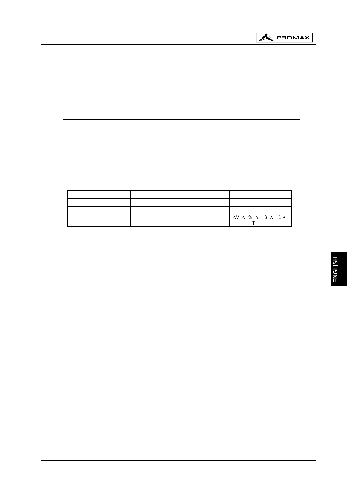
The most important di fferences bet ween each model can be fo und in t he followi ng
table:
OD-514B OD-515B OD-545B
Bandwidth 40 MHz 60 MHz 60 MHz
Delay sweep system NO NO SI
Cursor readout NO NO
are sturdy, easy to operate and exhibit hig h
V, 'V%, 'VdB, 'T, 1/'T,
'
DUTY, PHASE
Additionally, the oscilloscopes offer several other features:
High intensity CRT with high acceleration voltage
:
The CRT is a high beam transmission and high intensity type with a high acceleration
voltage of 2 kV for
OD-514B
and 12 kV for
OD-515B
and
OD-545B
. It displays clear
readable traces even at high sweep speeds.
A trigger level lock function
This circuit elimin ates the procedur es of the troubles ome trigg ering adj ustment not only for
displaying signals but a lso for tha t of vide o signals an d la rge du t y-cycle signa ls.
TV sync triggering:
The oscilloscope has a sync separat o r circuit f or TV-V and TV-H signa ls tr iggerin g.
X-Y operation mode
In this mode horizont al deflection (X-a xis) is v ia CH1 signal and vertic al deflecti on (Y-axis)
is via CH2 signal.
CH1 Output:
CH1 output located on rear panel can be applied to frequency counter or other instruments.
Z-Axis Input:
Beam intensity modulation capability permits time or frequency markers to be added. Trace
blank with positive signal, TTL compatible.
November 2000
Page 1
Page 5
OD-514B, OD-515B & OD-545B INSTRUCTION MANUAL
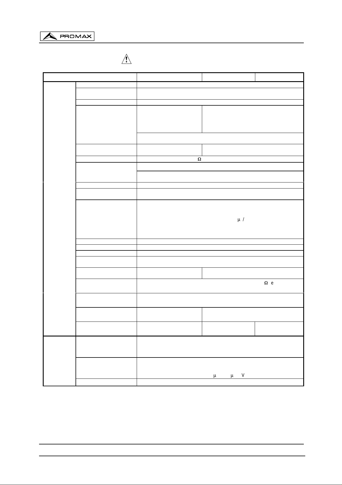
1.2 Specifications
SPECIFICATION / MODEL OD-514B OD-515B O D - 5 45B
VERTICAL
AXIS
Sensitivity
Accuracy
Vernier vertical sensitivity To 1/2.5 or less of panel-indicated value.
Frequency bandwidth
Rise time
Input impedance 1 M: ±2% // Approx. 25 pF
Square wave characteristics
Other distortions and other ranges: 5% added to the above value. (10ºC to 35 ºC)
DC balance shift
Linearity
CH1: CH1 single channel.
CH2: CH2 single channel.
DUAL: CH1 & CH2 channels. CHOP/ALT are auto-set by TIME/DIV switch.
Vertical modes
ADD: CH1 + CH2 algebraic addition.
Chopping repetition frequency Approx. 250 kHz
Input coupling AC, DC, GND
Maximum input voltage 400 V (DC + AC peak), AC: frequency 1 kHz or lower.
Common mode rejection ratio
Isolation between channels
(At 5 mV/DIV range)
CH1 signal output
CH2 INV BAL.
5 mV ∼ 5V/DIV: ≤ 3%, 1 mV ∼ 2 mV/DIV: ≤ 5% (10ºC to 35ºC)
5mV~2V/DIV:
DC~40MHz (-4 dB)
5V/Div:DC~40MHz (-5dB)
1mV~2mV/DIV:
DC~10MHz (-3dB)
(With reference to 100kHz, 8 DIV. Frequency response with –3 dB.)
5 mV ∼ 5 V/DIV: ≈ 8.75 ns
1 mV ∼ 2 mV/DIV: ≈ 35 ns
< ±0.1 DIV of amplitude change when waveform of 2 DIV at graticule centre is
(CHOP:0.5 s ∼ 5 ms/DIV, ALT: 2 ms ∼ 0.1 Ps/DIV)
When CHOP switch is pushed in, the two traces are displayed in the
CHOP mode at all range.
>
1000:1 at 50 kHz
>30:1 at 35 MHz
Approx. 100 mV/DIV without termination, 50 mV/DIV with 50 : termination.
Bandwidth (-3 dB): OD-514B: 20 MHz, OD-515B & OD-545B: 40 MHz
Balanced point variation: ≤ 1 DIV (Reference at centre graticule.)
1 mV ∼ 5V/DIV, 12 steps in 1-2-5 sequence
(5 DIV at the centre of display)
5 mV ∼ 5 V/DIV: DC ∼ 60 MHz,
1 mV ∼ 2 mV/DIV: DC ∼ 15 MHz
AC coupling: Low limit frequency 10Hz.
5 mV ∼ 5 V/DIV:≈ 5.8 ns,
1 mV ∼ 2 mV/DIV: ≈ 23 ns
Overshoot: ≤ 7% (At 10 mV/DIV range)
(5 DIV at the centre of display)
5 mV ∼ 5 V/DIV: ±0.5 DI V, 1 mV ∼ 2 mV/DIV: ±2.0 DI V
moved vertically.
50:1 or better at 50 kHz sinusoidal wave.
(When sensitivities of CH1 and CH2 are set equally)
> 1000:1 at 50 kHz
> 30:1 at 60 MHz
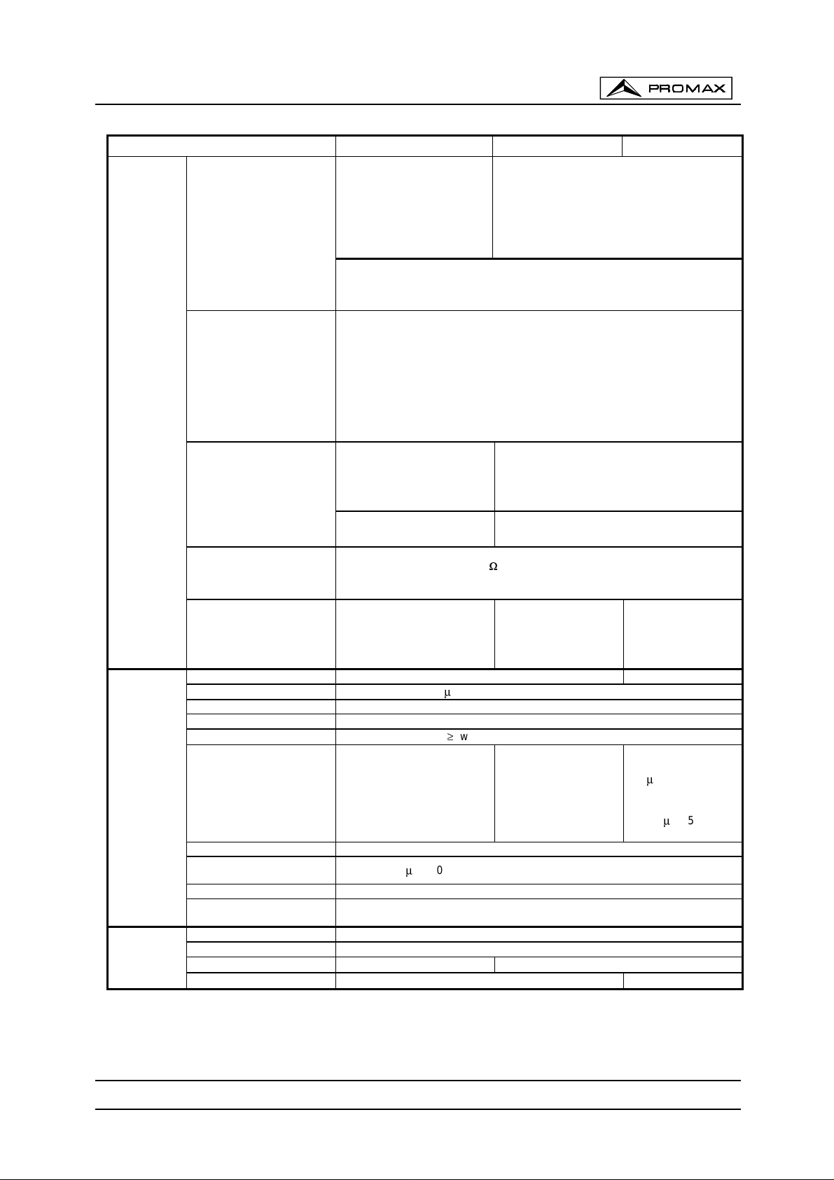
TRIGGERING
Page 2
Dynamic range
Signal delay
Triggering source
Coupling
Polarity
> 8 DIV at 20 MHz
> 4 DIV at 40 MHz
--- --- Leading edge can be
CH1, CH2, LINE, EXT (CH1 and CH2 can be selected only when the vertical
mode is DUAL or ADD). In ALT mode, if the TRIG. ALT switch is pushed in, it can
be use for alternate triggering of two different source. )
AC, HF-REJ, TV, DC
(TV-V/TV-H can be auto-set by TIME/DIV range. TV-V: 0.5 s-0.1 ms/DIV;
TV-H: 50 Ps ∼ 0.1 Ps/DIV)
/
+
−
> 8 DIV at 50 MHz
> 5 DIV at 60 MHz
monitored.
November 2000
Page 6
OD-514B, OD-515B & OD-545B INSTRUCTION MANUAL
SPECIFICATION / MODEL OD-514B OD - 5 15B OD-5 45B
DC ∼ 5 MHz: 0.5 DIV
Sensitivity
(EXT: 0.1 V)
5 ∼ 20 MHz: 1.5 DIV
(EXT: 0.2 V)
20 ∼ 40 MHz: 2 DIV
DC ∼ 10 MHz: 0.5 DIV (EXT: 0.1 V)
10 ∼ 50 MHz: 1.5 DIV (EXT: 0.2 V)
50 ∼ 60 MHz: 2.0 DIV (EXT: 0.3 V)
(EXT: 0.3 V)
TV (video signal): 2.0 DIV (EXT: 0.2 V)
AC coupling: Attenuate signal components < 10 Hz.
HF-REJ: Attenuate signal components > 50 kHz.
AUTO: Sweeps run in the free mode when no triggering input signal is applied.
(Applicable for repetitive signals of frequency 50 Hz or over.)
NORM: When no triggering signal is applied, the trac e is in the REA DY stat e and
Triggering modes
SINGLE: One-shot sweep with triggering signal. Can be reset to the READY state by
TRIGGERING
not displayed.
means of the RESET switch.
The READY lamp (LED) turns on when in the
READY state or in the sweep operation.
HORIZONTAL
AXIS
X-Y MODE
LEVEL LOCK and ALT
Satisfies the value of the
above trigger sensitivity plus
1DIV (EXT: 0.1 V) for signal of
duty cycle 20:80.
Repetition frequency:
Satisfies the value of the above trigger sensitivity
plus 0.5 DIV (EXT: 0.05 V) for signal of duty
cycle 20:80.
Repetition frequency: 50 Hz ∼ 40 MHz
50 Hz ∼ 40 MHz
EXT triggering signal input
Input impedance
Max. input voltage
100 V (DC + AC peak), AC: Frequency not higher than 1 kHz
1 M: ±2% // approx. 35 pF
The triggering signal
B triggering signal.
of main sweep is
used as the B
triggering signal.
Horizontal axis display A A, A INT, B, B TRIG'D
A sweep (main sweep) time 0.1 Ps ∼ 0.5 s/DIV, 21 steps in 1-2-5 sequence
Sweep time accuracy ± 3%, (10 ºC to 35 ºC)
Vernier sweep time control
1/2.5 of panel-indicated value
≤
Hold off time Continuous variable twice sweep length (time) at 0.1 µs ~ 1 ms/DIV ranges.
B sweep delay system
Continuous delay and
triggered delay
B sweep time
(delay sweep)
Sweep time accuracy
Delay time
Delay jitter
--- ---
0.1 Ps ∼ 0.5 ms/DIV,
12 steps
3%, (10 to 35 ºC)
±
1 Ps ∼ 5 ms
1/10000
≤
Sweep magnification 10 times (maximum sweep time 10 ns/DIV)
x10 MAG sweep time
accuracy
Linearity
Position shift caused by
x10MAG
0.1 Ps ∼ 50 ms/DIV ±5%, 10 ns ∼ 50 ns/DIV ±8% (1 0 º to 35ºC)
NORM: ±3%, x10MAG: ±5% (±8% for 10 ns ∼ 50 ns/DIV)
Within 2 div. at CRT screen centre
Sensitivity Same as vertical axis: (X-axis: CH1 input signal; Y-axis: CH2 input signal.)
Accuracy NORM: ± 4%, x10MAG: ± 6% (10º to 35 ºC)
Frequency bandwidth
X-Y phase difference
DC ∼ 1 MHz (-3dB) DC ∼ 2 MHz (-3dB)
3º at DC ∼ 50 kHz
≤
3º at DC ∼100 kHz
≤
November 2000
Page 3
Page 7
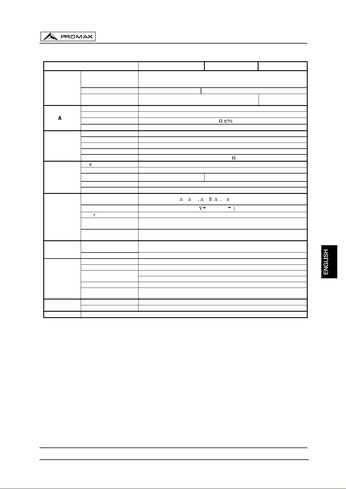
SPECIFICATION / MODEL OD-514B OD-515B O D - 5 45B
EXT HOR
MODE
Z AXIS
CALIBRATION
VOLTAGE
CRT
CURSOR
READOUT
(OD-545B
only)
POWER
SUPPLY
OPERATING
ENVIRONMENT
MECHANICAL
FEATURES
ACCESSORIES
OD-514B, OD-515B & OD-545B INSTRUCTION MANUAL
Sensitivity
Frequency bandwidth
Phase difference between
vertical axis
Sensitivity 3 Vp-p (Trace becomes brighter with negative input.)
Frequency bandwidth
Input impedance
Maximum input voltage
Waveform Positive-going square wave
Frequency 1 kHz ±5%
Duty ratio 48:52
Output voltage 2 Vp-p ±2%
Output impedance
Type 6-inch rectangular type, internal graticule.
Phosphor P 31
Acceleration voltage
Effective screen size 8 x 10 DIV (1 DIV = 10 mm (0.39 in))
Graticule Internal; continuous adjustable illumination (OD-515B & OD-545B only)
Cursor measurement
functions
Cursor display format
Cursor resolution 1/25 DIV
Effective cursor range from
centre graticule
Panel setting display
Mains voltage
Consumption 60 W
Indoor use
Altitude up to 2000 m
Temperature range
Relative humidity R. H. 85% (maximum value) non condensing
Storage temperature
& humidity
Dimensions 310 W x 150 H x 455 D (mm)
Weight Approx. 8.2 Kg (18 lbs)
Power cord CA-006
Approx. 0.1 V/DIV (Trace swept by an external horizontal signal applied to the
EXT TRIG IN terminal. Vertical axis modes are CH1, CH2, DUAL and ADD
DC ∼ 1 MHz (-3 dB) DC ∼ 2 MHz (-3 dB)
50 V (DC + AC peak, AC frequency≤ 1 kHz )
Approx. 2 kV Approx. 12 kV
V/DIV, V-MODE, INV, ALT/CHOP, UNCAL, ADD (SUB), x10 MAG,
PROBE (x1 / x10), X- Y, A T/D, TV-V/H, B T/D
100 V, (90 to 110 V), 120 V (108 to 132 V), 220 V (198 to 242 V),
230 V (207 to 250 V) AC selectable, 50 or 60 Hz
modes in the CHOP mode.)
3º at DC ∼ 50 kHz
≤
DC ∼ 5 MHz
5 k
:±
Approx. 2 k
V%,'VdB, 'T, 1/'T, DUTY, PHASE
'V,'
(DELTA),
¦
Vertical: ±3 DIV
Horizontal: ±4 DIV
To satisfy specifications: 5 º to 35 ºC
Maximum operating ranges: 0º to 40 ºC
-10 º to 70 ºC, R.H. 70% (maximum)
:
(REF)
3º at DC ∼ 100kHz
≤
Page 4
November 2000
Page 8

OD-514B, OD-515B & OD-545B INSTRUCTION MANUAL
2. SAFETY RULES
2.1 General
* Use this equipment connected
measurement connected to ground potential
* This is a
corresponding
Class I
equipment, for safety reasons plug it to a supply line with the
ground terminal
* This equipment can be used in
Degree 1
environments.
only to systems with their negative of
.
.
Overvoltage Category II
installations and
* When using some of the following ac cessori es use onl y the
safety.
Mains (Power) cord.
* Observe all
* Remember that voltages higher than
* Use this instrume nt un der the
The user is only authorised to
*
Mains fuse replacement, that should fit indicated
specified ratings
both of supply and mea su r emen t.
60 V DC
30 V AC rms
or
specified environmental conditions
carry out the following maintenance operations:
type
and
value
On the Maintenance section proper instructions are given.
specified
ones to ensure
are dangerous.
.
.
Pollution
Any other change on the equipment should be carried out by qualified personnel.
*The
*
* Follow the
negative of measurement
is at ground potential.
Do not obstruct the ventilation system
cleaning conditions
described in the Maintenance paragraph.
of the instrument.
November 2000
Page 5
Page 9
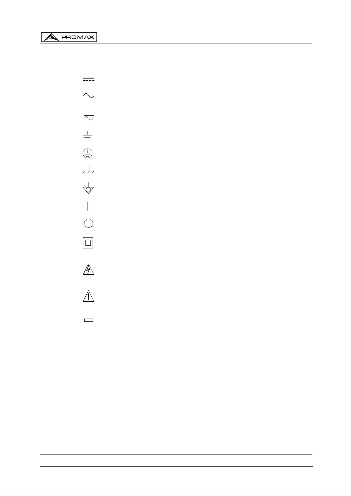
* Symbols related with safety:
DIRECT CURRENT
ALTERNATING CURRENT
DIRECT AN D AL TERNATING
GROUND TE RM I N AL
PROTECTIVE CONDUCTOR
FRAME TERMINAL
EQUIPOTENTIALITY
OD-514B, OD-515B & OD-545B INSTRUCTION MANUAL
ON (Supply)
OFF (Supply)
DOUBLE INSULATION
(Class II protection)
CAUTION
(Risk of electric shock
CAUTION REFER TO MANUAL
FUSE
)
Page 6
November 2000
Page 10

OD-514B, OD-515B & OD-545B INSTRUCTION MANUAL
2.2 Specific precautions
1. Do not use the equipment immediately after moving it to a room with very different
temperature. Wait for a while until the equipment reaches room temperature.
2. Do not apply voltages that exceed the limits of probes or input connectors.
2.3 Descriptive Examples of Over-Voltage Categories
Cat I
Cat II
Cat III
Cat IV
Low voltage installations isolated from the mains
Portable domestic installations
Fixed domestic installations
Industrial installations
November 2000
Page 7
Page 11

OD-514B, OD-515B & OD-545B INSTRUCTION MANUAL
Page 8
November 2000
Page 12
OD-514B, OD-515B & OD-545B INSTRUCTION MANUAL
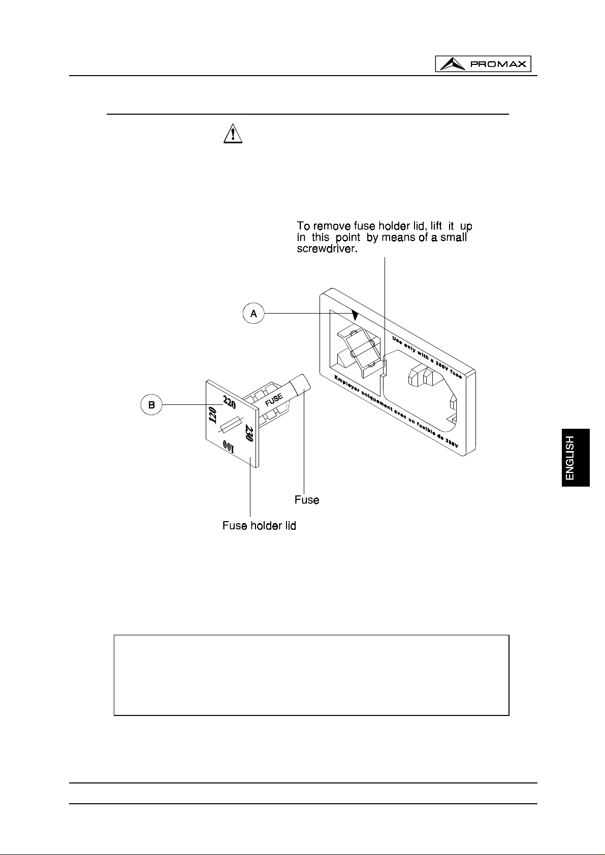
3. INSTALLATION
3.1 Power Supply
OD-514B, OD-515B
The
and
OD-545B
oscilloscopes can be powered with mains
voltages of 100, 120, 220 or 230 V AC 50-60 Hz. Mains voltage (line voltage) can be
selected from the mains socket.
1.-
Remove fuse holder lid
2.-
Fit the suitable fuse for t he se le cted main s vo ltage .
3.-
Replace the fuse holder lid, aligning
November 2000
Figure 1.-
Mains voltage change.
[A]
mark with the desire d ma in s vo ltag e mar k
[B]
CAUTION:
FACTORY SETS INSTRUMENT MA INS VOLTAGE TO 230 V
BEFORE PLUG THE INSTRUMENT TO THE MAINS, SET THE VOLTAGE
SELECTOR PROPERLY AND CH ECK THAT FUSE VALUE CORRES PONDS TO
THE MAINS VOLTAGE VALUE.
Page 9
Page 13

3.2 Handle position
OD-514B, OD-515B & OD-545B INSTRUCTION MANUAL
OD-514B, OD-515B & OD-545B
oscilloscopes have a movable handle for
transport and f o r posit io ning the oscillosco pe to ob tain t h e be st angle w ith the disp la y.
To change ha ndle position, take the h andle supports that are in c ontact with the
oscilloscope chassis and de tach slig htly f rom th e chassis so you can change it s posit ion .
Page 10
November 2000
Page 14

OD-514B, OD-515B & OD-545B INSTRUCTION MANUAL
4. INSTRUCTIONS
4.1 Description of controls and elements
Figure 2.- OD-514B
frontal panel.
November 2000
Figure 3.- OD-515B
frontal panel.
Page 11
Page 15

OD-514B, OD-515B & OD-545B INSTRUCTION MANUAL
Figure 4.- OD-545B
frontal panel.
Oscilloscope frontal panel is zone-divided according to the controls functions:
VERTICAL, TRIGGER, HORIZONTAL
, etc. The following paragraphs describe the controls
and elements of th e fr on tal pa ne l gr oupe d a cco rding to t hat fu nct io nal zones.
[9]
[8]
[1]
I/O
. Main power switch of th e in st rum en t.
POWER
CAL
. It lights when the I/O switch of th e oscillo sco pe is ON.
. The terminal provi des a calibrated amplitu de square wave of 2 V p-p at 1
kHz for probe adjustment and vertical amplifier calibration.
CRT
[2].
[3]
[4]
[5]
INTEN.
Control the brightness of the spot or trace. The brightness increases
when turning the control clockwise.
B INTEN. (OD-545B
only) Control the brightness of the spot or trace when in
sweep delay (B) mode.
FOCUS
TRACE ROTATION
. Focus the trace to the sharpest image.
. Semi-fix potentiometer for aligning the horizontal trace in
parallel with graticule lines.
Page 12
[6]
[7]
ILLUM.
(Except
READOUT INTEN. (OD-545B
OD-514B
). Graticule illuminat ion adju st m ent .
only) Semi-fixed potentiometer for adjusting
intensity of the readout and cursors.
[42] CRT screen with internal graticule.
November 2000
Page 16

OD-514B, OD-515B & OD-545B INSTRUCTION MANUAL
VERTICAL AXIS (VERTICAL)
[12]
CH1 (X
). The input termin al of vertical ch annel CH1. I n X-Y operati on mode i s
X-axis.
[16]
[11] [15]
CH2 (Y
). Input terminal of vertical channel CH2. In operation mode X-Y is Y-axis.
AC/GND/DC
. Select connection mode between input terminal and vertical
amplifier for channel CH1 and CH2 respectively.
AC
GND
Blocks DC component of th e inpu t sign a l.
Connect the vertical amplifier of the CH1-CH2 to ground, establishin g a
ground reference.
DC
Connect CH1-CH 2 amplifier to the input terminal, visualising AC & DC
component of the signal.
[10] [14]
VOLTS/DIV
. Selects the CH 1/C H2 v ertic al ax is s ens itiv ity fr om 5 mV/D IV to
5 V/DIV with 12 ranges totally.
[13] [17]
VARIABLE
. Fine adjustment of sensitivity of CH1 & CH2 vertical axis respectively
with a factor of ≥ 1/2.5 of the indicated value. The sensitivity is calibrated to
VARIABLE
control.
[40] [37]
specific value in the CAL position of
POSITION. Vertical positioning control of the CH1/CH2 trace on the CRT
display. Clockwise turning shifts trace up and anticlockwise turning shifts trace
down.
[39] MODE. Select operation mode of CH1 and CH2 amplifiers.
CH1 Operate the oscilloscope as a single-channel instrument by selecting
CH1 alone.
CH2 Operate the oscilloscope as a single-channel instrument by selecting
CH2 alone.
DUAL Operate the oscilloscope as a dual-channel instrument by selecting
CH1 and CH2 (see control [41] description).
ADD The oscilloscope displays the algebraic sum (CH1 + CH2) or
subtraction (C H1 - CH2) of the two signal s (the subtraction func tion
effects only when push in CH2 INV [36] button).
[41] CHOP. Operative in DUAL mode only.
Switch engaged CH1 & CH2 signal traces are chopped and displayed
[36] CH2 INV. Inverts CH2 signal polarity.
[20] Gr ound terminal.
TRIGGERING
[23] EXT TRIG (EXT HOR). Input terminal is use d in common for exter nal triggering
November 2000
simultaneous ly . Th at is , eac h hori z o nt al sweep of the electrons beam of th e C RT .
Normally used at slower sweep speeds.
signal and extern al horizontal signal. To use t his terminal, set SOURCE swit ch
[26] to the EX T posit i on.
Page 13
Page 17

OD-514B, OD-515B & OD-545B INSTRUCTION MANUAL
[26]
[24]
[25]
SOURCE
CH1 (X-Y)
. Selects the triggering source:
Selects CH1 signal as the triggering source when VERT MODE
switch [39] is set to DUAL or ADD. When in the X-Y mode, select
CH1 for the X-axis signal.
CH2
Selects CH2 signal as the triggering source when VERT MODE
switch [39] is set to DUAL or ADD.
LINE
Selects a pulse from the AC line. This allows the oscilloscope to be
stabilised for the pulses of the signal of the AC line even if those are
very small in relatio n to ot her sign al compon en t s.
EXT
Selects the signal applied through
source.
When in the X-Y, EXT HOR mode, the X-axi s operat es with
EXT
terminal [23] as triggering
the external sweep signal.
TRIG ALT
. When the VERT MODE switch [39] is set in the DUAL or ADD state,
and the SOURCE swit ch [ 23] i s sel ected at C H1 or CH 2, with the enga geme nt of
the TRIG.ALT switch, it will alternately select CH1 & CH2 for the internal
triggering source signal.
COUPLING.
Select COUPLING mode between triggering source signal and
trigger circuit; select connection of TV sync trigger circuit.
AC:
DC:
HF REJ:
TV:
AC coupling.
DC coupling
Removes signal components above 50 kHz (-3 dB).
The trigger circuit is connected to the TV sync separator circuit
and the triggered s weeps synchroni se with TV-V or T V-H signal
at a rate selected by the TIME/DIV switch [18]
[22]
[30]
[29]
[31]
TV-V: 0.5 s/DIV - 0.1 ms/DIV
TV-H: 50 µs/DIV - 0.1 µs/DIV
SLOPE
. Selects the trigge ring slope.
+
Triggering occ urs when the tr igg erin g si gnal c ross es the tri gg erin g lev el
in positive-going d irection .
-
Triggering occ urs when the tr igg erin g si gnal c ross es the tri gg erin g lev el
in negative-going direction.
LEVEL
. Selects the amplitude of the sig nal that mak es the triggering occur when
in TRIGGER NORM. That is, the start point of the waveform. When turning it
clockwise (+), the triggerin g level moves upwar d on the display wavef orm. When
turning it anticlockwise (-), the triggering level moves downward on the display
waveform.
LOCK
. Triggering level is automatically maintained at optimum value irrespective
of the signal ampl itu de (fr om v ery sm all to l arge am plitu des), r equi rin g no man ual
adjustment of triggering level.
HOLD OFF
. Used when the signal waveform is complex and stable triggering
cannot be attained with the LEVEL knob alone.
Page 14
November 2000
Page 18

OD-514B, OD-515B & OD-545B INSTRUCTION MANUAL
[28]
MODE
. Select the desired trigger mode.
AUTO
When no triggering si gn al i s a p pl ied or when trig ger i n g si g nal fr e qu ency
is less than 50 Hz, sweep runs in the free run mode.
NORM
When no trigg ering si gnal is a pplied, sweep is in a rea dy st ate and the
trace is blanked out. Used primarily for observation of signal ≤ 50 Hz.
SINGLE
Use for single sweep. ( E xcept
OD-514B
Push to RESET: Operation (one-short triggering operation), and in
common as the reset switch. When these three buttons are disengaged,
the circuit is in the single tr i gg er m od e. Th e ci r cui t i s r es et as t hi s b utt o n
is pressed. W hen the circuit is reset, t he READY lamp t urns on. The
lamp goes out when the single sweep operation is over.
TIME BASE OR HORIZONTAL CHANNEL (HORIZONTAL)
[18]
[19]
TIME/DIV
OD-545B
. Select the s w eep time of the A s w eep. (A and B s w ee p i n common for
only, B TIME/DIV < A TIME/DIV)
SWP. UNCAL.
Activates
SWP VAR
control. TIME/DIV [18] c alibra tions are ex act
only when this key is not pushed in.
[21]
SWP. VAR.
Vernier control of sweep time. When
pushed in, the s weep time c an be made slower by a factor ≥ 2.5 of the in dicated
value.
)
SWP.UNCAL
[19] button is
[34]
POSITION. Horizontal posi tioning control of the traces on the CRT displ ay.
When turning this control clockwise the trace moves to the right on the CRT.
When turning this control anticlockwise the trace moves to the left on the CRT.
[33] x 10 MAG. Expands horizontal deflection 10 times, multiplying per 10 the
horizontal sensitivity in X-Y operation mode and the effective sweep speed.
[38] HORIZ. DISPLAY MODE (OD-545B only)
Select swe ep mode s as fo llows:
A: Main sweep (A sweep) mode for general waveform observation.
A INT: This sweep mode is used when selecting the section to be
magnified of A sweep, in preparation for delayed sweep. The B
sweep sectio n (delayed sweep) cor responding to the A sw eep is
displayed with a high intensity beam.
B: Display the delayed swee p (B sw eep) a lone.
B TRIG‘D: Select between continuous delay and triggered delay.
Disengaged: For continuous delay. The B sweep starts
immediately after the sweep delay time set by A
TIME/DIV and B TIME/DIV switch and DELAY
TIME knob has elapsed.
Engaged: For triggered delay. The B sweep starts when the
triggering pulse is applied after the sweep delay
time set by A TIME/DIV and B TIME/DIV switch and
DELAY TIME knob has elapsed.
(The triggering s ignal is used in common f or both A swee p and B
sweep).
November 2000
Page 15
Page 19

OD-514B, OD-515B & OD-545B INSTRUCTION MANUAL
READOUT FUNCTION
(Only available in
OD-545B
)
[38] CURSOR measurement
CURSOR ON/OFF
CURSOR FUNCTION.
∆
V Voltage difference measurement.
∆
V% Voltage difference measurement in percentage
. Press the button to turn on/off the cursor measurement.
Press the button to select the measurement functions.
(5 div =100% ref.)
∆
VdB Voltage gain measurement
(5 div = 0dB ref. , ∆VdB = 20 log∆div/5div)
∆
T Time difference measurement.
1/∆T Frequency measurement.
DUTY Duty cycle or time difference percent (∆T%)
measurement (5 div =100% ref.)
PHASE Phase measurement (5 div = 360° ref.)
TRACK -∇ -
selected curs or is indicat ed by either a
(REF): Press the button to sel ect the cursor(s ) to be m oved. Th e
∇
or symbol. When both symbols are
displayed, the two curso rs can be sh ifted simu ltan eou sly.
[35] POSITION. Rotate the cursor POSITION control to position the selected
cursor(s). When HORZ. DISPLAY mode is set A INT or B state and CURSOR
ON/OFF is set OFF, the POSITION contr ol is used in common as the DELAY
TIME.
READOUT ON/OFF To turn on/off the readout status on the CRT, press the
CURSOR ON/OFF and CUR SOR FUNCTION buttons at
the same time.
PROBE x1 / x10 To indicate the voltage readout is scaled for x1 or x10
probe, press the TRACK -∇ - (REF) button and rotate
the cursor POSITION at the same time.
Page 16
November 2000
Page 20

OD-514B, OD-515B & OD-545B INSTRUCTION MANUAL
Rear Panel
[45]
Z AXIS INPUT
Figure 5.-
. Input termina l f or ex ternal CRT int ensi ty modul ati on s ignal . Tr ac e
Rear panel.
brightness is r ed uc e d wh en a p osi ti v e si g nal is ap pl i ed and it i s i ncr e ase d when a
negative signal is applied.
[46]
CH1 OUTPUT
input. Deliv ers the CH 1 signal wi th a voltage of approximately
100 mV per 1 DIV of graticule. When terminated with 50
:
, the signal is
attenuated to about one half. Suitable for frequency counting, etc.
[47] Power input connector. It allows to connect or disconnect the mains cord.
[48] Fuse and line voltage selector. It allows to change the operating voltage range.
[49] Studs for laying the oscilloscope on its back to operate it in the upward posture.
Also used to take up th e po we r cord .
November 2000
Page 17
Page 21

4.2 Start Up
4.2.1 Preliminary Operations
Before switching on the in st rume nt, per form t he fo llo wing op erat ion s and che cks:
1. Set the controls as indicated:
CONTROL Nº STATE
I/O
INTEN
FOCUS
ILLUM
VERT MODE
CHOP
CH2 INV
POSITION
VOLTS/DIV
VARIABLE
AC/GND/DC
SOURCE
COUPLING
SLOPE
TRIG.ALT
LEVEL LOCK
HOLDOFF
TRIGGER MODE
HORIZ. DIS. MODE
TIME/DIV
SWP.UNCAL
POSITION
x10 MAG
X-Y
OD-514B, OD-515B & OD-545B INSTRUCTION MANUAL
[9] OFF (disen ga ge d )
[2] Mid-position
[4] Mid-position
[6] Full anti-clockw ise posit ion
[39] CH1
[41] Released (ALT)
[36] Released
[40][37] Mid-position
[10][14] 0.5 V/DIV
[13][17] CAL (clockwise position)
[11][15] GND
[26] CH1
[25] AC
[22] +
[24] Released
[29] Pushed in
[31] MIN (ant i-clockw ise )
[28] AUTO
[38] A (OD-545B only)
[18] 0.5 ms/DIV
[30] Released
[34] Mid-position
[33] Released
[27] Released
Page 18
Table 1
Connect power c ord to power input co nnector [47], then connec t it to an AC li ne
outlet suitable for the instrument previously set AC line voltage, and then continues as
follows:
1. Press the I/O switch [9]. T he POWER led [8] will be on. In about 20 seconds, a
trace will appear on the CRT screen. If no trace appears in about 60 seconds,
check the switch and contro l set ting (pre viou s tab le).
2. Adjust the trace to an appropriate brightness and image with INTEN [2] and
FOCUS [4] control knob respectively.
November 2000
Page 22

OD-514B, OD-515B & OD-545B INSTRUCTION MANUAL
WARNING
Ageing-resistan ce material has been used in t he CRT. In any case, th e
screen can be damag ed if a spot or a trace extr emely bright is s et on it
for a long time. So if an intense brightness is needed for a measurement
make sure to decrease intensity (INTEN) just after the measurement is
performed. You should get used to decrease brightness when your not
going to observe the oscilloscope for a while too.
3. Align the trace with the horizontal central line of the graticule by adjus ting the
CH1
4. Adjust the
POSITION
[40] control knob .
POSITION
[34] control knob to align the left end of the trac e with
the graticule lef t en d lin e.
4.2.2 Trace Rotation Adjustment
Preadjust the instrum ent until a trace jus t as i ndicated i n the prev ious par agrap h is
obtained.
CH1
[5]
POSITION
Align the trace with the horizon tal centr al line o f the gr aticule by adjustin g the
control knob [40].
Is the trace is not parallel to the central line, adjust the
TRACE ROTATION
potentiometer by means of a suitable screwdriver until the trace becomes parallel.
4.2.3 Probe Compensation
Probe compensation desadjustment is, frequently, a measurement errors source.
Attenuated probes include a compensation adjustment. Get used to check probe
compensation before performing the measurements to assure optimum conditions
measurements.
Set the instrument as indicated in section 4.2.1.
CH1
input termi nal [12] and connect the pr obe tip to
CAL 2 Vpp
the
Connect a prob e (x10) to the
terminal [1]. On the CRT screen should b e displayed a square wave form
with four divisions amplitude (4 x 0.5 V/DIV = 2 Vpp).
If the display ed waveform is distor ted, adjust the comp ensation trimmer on probe
for optimum square wave (minimum overshoot, rounding off and tilt). See figure 6.
November 2000
Figure 6.-
Probe Compen sat io n.
Page 19
Page 23

OD-514B, OD-515B & OD-545B INSTRUCTION MANUAL
to
Remove the pro b e fro m
CH2
position and repeat the process for
CAL 2 Vpp
terminal [1]. Set s wi tch
CH2
, each one with its own probe.
VERTICAL-MODE
[39]
Now the oscilloscope is read y to be used.
4.3 OPERATION METHOD
4.3.1 Single-Channel Operation
Single trace and base time operation and internal triggering is the most basic
operating mode of t he
only one signal to be observed, without the inconvenience of other traces on the CRT
screen. Due it is a two channel oscilloscope, any of these two channels can be selected.
CH1 is provided wi th and outp ut ter minal : us e t he
measure signal frequenc y using a frequ ency count er while obs erving wav eform. CH2 hav e
a switch that inverts polarity, although it adds flexibility, it has no use when operating in
single trace mode.
OD-514B, OD-515B
1. Set the following controls of the instrument as shown below. Observe the
selected triggering source (CH1 or CH2 SOURCE) corresponds to the selected
channel (CH1 or CH2 V MODE).
OD-514B, OD-515B & OD-545B
CH1
OD-545B
and
are set for single channel operation as follows:
. Select this m ode when there is
output terminal on the re ar pan el to
CONTROL Nº STATE
I/O
VERT MODE
POSITION
VOLTS/DIV
VARIABLE
AC/GND/DC
SOURCE
TRIGGER MODE
TIME/DIV
SWP. UNCAL
POSITION
X-Y
[9] ON (engage position)
[39] CH1 (CH2)
[40][37] Mid-position
[10][14] 0.5 V/DIV
[13][17] CAL clockwise position
[11][15] AC
[26] CH1 (CH2)
[28] AUTO
[18] 0.5 ms/DIV
[30] Released
[34] Mid-position
[27] Released
Table 2.-
2. Position trac e near the centre of th e screen by means of the
control [37] or
POSITION
control [40] (depending on the channel selected).
3. Connect the si gnal to be observe d to the appropri ate inp ut terminal
CH2
[16] and adj ust the appropri ate
VOLTS/DIV
selector [10] or [14] so that
signal waveform is completely displayed on the screen.
POSITION
CH1
[12] or
Page 20
WARNING
Do not apply signal higher than 400 V (DC + AC peak)
November 2000
Page 24

OD-514B, OD-515B & OD-545B INSTRUCTION MANUAL
4. Set
TIME/DIV
[18] so that the appropriate number of signal cycles appears on
screen. For some measurements the appr opriate number of cycles is only two
or 3 cycles; for other measurements the appropriate number of cycles is 50-100
(displayed as a band). If necessary, adjust Trigger
stable display of the signal.
5. If the frequency of signal is so high that even in the 0.1
TIME/DIV [18] selector appears too many cycles on screen, push the x10 MAG
key [33]. This increases the effective sweep speed 10 times, so 0.2 Ps/DIV
position now c orrespo nds to 20 ns/ DIV, 0.5 Ps positio n corresp onds to
50 ns/DIV, etc.
6. If the frequency of the signal is very low or its zero (DC signal), so the AC
coupling atte nuates or distor ts the sign al, set AC/GND/DC [11] or [15] select or
to DC.
4.3.2 Dual-Channel Operation
Dual-Channel operation is the main operation mode of the OD-514B, OD-515B
and OD-545B.
Set VERT MODE [39] selector to the DUAL position so the channel 2 signal is
displayed too.
LEVEL
control [30] for a
P
s position of the
following exceptions:
according to:
will not be stable.
November 2000
Figure 7.-
The operation is identical to the one described in the section 4.3.1 with the
When in dual-ch annel o peratio n DUAL (or ADD), set Trigger SOURCE switch [26]
- If both channels are displaying signals of the same frequency, set th e Trigger
SOURCE swit ch [2 6] to th e chann e l wit h th e steepe st -s lo pe wa vef o rm.
- If the signals are different but they are harmonically related, trigger from the
channel carrying the lowest freque n cy.
- If the signals do not have the same frequency, engaging TRIG.ALT [24] both
signals will be synchronised.
Bear in mind to o that if th e channel us ed for tri ggering is disconnect ed, the ima ge
Page 21
Page 25

OD-514B, OD-515B & OD-545B INSTRUCTION MANUAL
Selection between
CHOP
mode and
TIME/DIV switch [18] sh own in Fi gure 8. T he
CHOP
mode and the
CHOP
push switch [41] is en gag ed, the two tr aces are dis pl ayed i n th e C H OP o per ati on at
2 ms/DIV and hig her
ALT
mode is automatically made by the
5 ms/DIV and lower
ranges are use d in the
ranges are used in the
ALT
mode. When the
all ranges. The CHOP operation has priority over the ALT operation.
Figure 8.-
4.3.3 ADD and SUBTRACTION Measurement
Add and subtraction operations are two types of dual-channel operation in which
the two signals are combined to display a unique trace. In ADD operation the resultant trace
displays the algebraic sum of the CH1 and CH2 signals. In subtraction operation the
resultant trace displays the algebraic difference of CH1 and CH2 signals.
Set the oscilloscope as shown below for ADD operation.
1. Set oscilloscope to dou ble - chan nel ope ra t ion a s show n in 4.3. 2.
2. Make sure that
and that
very different, set both
VOLTS/DIV
VARIABLE
[10] and [14] s elect ors ar e set to t he sa me p osition
[13] and [17] are set to
VOLTS/DIV
selectors to the position that completely
CAL
position. If signal levels are
displays on screen the signal with the highest amplitude.
3. Use the channel w ith th e highe st amp lit ude signa l f o r trig ge ring .
MODE
4. Set
selector [39] to
be the algebr aic sum of the C H1 and CH2 signals.
ADD
position. Thi s way the uniq ue r esul t a nt trace will
POSITION
[37] or [40] can
be used to positioning the resultant trace.
NOTE
If the input signa ls are in phase, th e amplitude of th e resultant tra ce
will be the arith m et i c su m o f t he individual tr ac es ( fo r ex. 4.2 d i v + 1.2
div = 5.4 div). If the phase differenc e of the input signals is 180º , the
resultant amplitud e is the arithm etic difference ( fore ex. 4.2 di v – 1.2
div = 3.0 div).
5. If the peak-peak amplitude of the resultant trace is very small, turn both
VOLTS/DIV
[10] and [14] selectors to increase the height of the displayed trace.
Make sure that both se lecto rs ar e set t o the same posit io n.
Page 22
November 2000
Page 26

OD-514B, OD-515B & OD-545B INSTRUCTION MANUAL
To obtain the subtrac tion, proceed as bef ore but now push the
CH2 INV
[36] key.
The resultant trace will be the algebraic difference of the CH1 and CH1 signals. Now, if the
input signals are in phase, the resultant trace will be the arithmetic difference of the
individual traces (for ex. 4.2 div – 1.2 div = 3.0 div). If the input signals have a phase
difference of 180 º, the resultant trace amplitude will be the arithmetic sum of the individual
traces (for ex. 4.2 div + 1.2 div = 5.4 div).
4.3.4 X-Y Operation and EXT HOR Operation
Select X-Y Operation engaging
X-Y
switch [27].
The internal sweep circuit is disconnected and trace in the horizontal direction is
driven by the signal selected by the
−
When the
SOURCE
switch is set to
an X-Y scope with the
−
When the
EXT HOR
SOURCE
[23] (external sw eep ) mod e.
SOURCE
CH1
signal for the
switch is set to
switch [26].
CH1 X-Y
EXT
position, the oscilloscope operates as
X-axis
.
position, the oscilloscope operates in the
X-Y Operation
X-Y
The
operation is wi th
X-axis becomes DC to 1 MHz (-3 dB) (or DC to 2 MHz for
Horizontal
Y-axis, both verti cal
control if the
POSITION
POSITION
VERT MODE
control [34 ] is directl y used as the X- axis PO SITION c ontrol. Fo r the
switch [39] is properly set.
CH1
as X-axis and
CH2
as Y-axis. The ba ndwidth of th e
OD-515B
and
OD-545B
) and the
controls [37] and [40] can be us ed as vertical P OSITION
NOTE: When high frequency signals are displayed in the X-Y operation, pay
attention to the frequency bandwidths and phase differences between X and Y
axis.
EXT HOR Operation
The external si gnal applied thr ough the
The Y-axis i s with a ny chann els as sel ected by the V ERT
EXT HOR
terminal [23] driv es the X-axis.
MODE
switch [39]. When
mode is selected, both CH1 and CH2 signals are displayed in the CHOP mode.
Figure 9.- Figure 10.-
DUAL
November 2000
Page 23
Page 27

OD-514B, OD-515B & OD-545B INSTRUCTION MANUAL
4.3.5 Triggering options
Frequently, triggering selections is the most complicated operation to perform when
using an oscilloscope due to the many options available and the concrete requirements of
some signals.
1.- Tri g gering So urce Selection (SOURCE [2 6 ] )
The displaye d signal itsel f or a trigger si gnal which h as a time relati onship wit the
displayed sig nal is req uired t o be appli ed to th e trigger circuit to displ ay a stationar y sig nal
on the CRT screen. The
SOURCE
switch [26] is used for selecting such a triggering
source.
CH1
The internal triggering method which is used most commonly.
CH2
The signal applied to the vertical input terminal is branched off from the
preamplifier and is fed to the trigger circuit through the VERT
MODE
switch
[39]. Since the triggering signal is the measured signal itself, a stable
waveform can be readily displayed on the CRT screen. When in the DUAL or
ADD operation, the signal s elected by the
SOÜRCE
switch [26] i s used as
the triggering source signal.
LINE
EXT
The above trig ger ing source si g nal s el ec ti o n functions are s h ow n collectiv ely i n the
following table.
SOURCE/ VERT.MODE CH1 CH2 DUAL ADD
The AC power line frequency signal is used as the triggering signal. This
method is effective wh en t he measured si gn al has a r el ati o nship with the AC
line frequency, es pecially for measurem ents of low level AC noise of audio
equipment, thyristor circuits, etc.
The sweep is trig gered wi th an exter nal sig nal appli ed to th e external trigger
input terminal (
EXT [23]
). An external signal which has a periodic relationship
with respect to the measured signal is used. Since the measured signal is not
used as the triggering signal, the waveforms can be displayed more
independent than the measured signal.
CH1
CH2
ALT
LINE
EXT
Triggered by CH1 signal
Triggered by CH2 signal
Alternately triggered by CH1 & CH2
Triggered by LINE signal
Triggered by EXT TRIG input signal
Page 24
Table 3.-
November 2000
Page 28

OD-514B, OD-515B & OD-545B INSTRUCTION MANUAL
2.- COUPLING control [25] functions
This switch is used for sel ecting the co upling of the tr iggering si gnal to the trigger
circuit in accordance with the characteristics of the measured signal.
AC
HF REJ
TV
This coupling is for AC triggering which is used most commonly. As the
triggering signal is applied to the trigger circuit throug h an AC coupling
circuit, stable triggering can be attained without being affected by the DC
component of the input signal. The low-range cut off frequency is 10 Hz
(-3 dB). When the ALT trigger mode is used and the sweep speed is
jitter
slow,
may be produced. In such a case, use the DC mode.
The triggerin g signal is fed to the trigger c ircuit through an AC co upling
circuit and a low pass filter (approximately 50 kHz, -3 dB). The higher
components of the trigger signal are rejected and only the lower
components are applied to the trigger circuit.
This coupling is for TV triggering, for observation of TV video signals. The
triggering signal is AC-coupled and fed through the triggering circuit (level
circuit) to the TV sync separator circuit. The separator circuit picks off the
sync signal, w hich is used to trigger t he sweep. Thus, the video signal
can be displayed st ably. Bei ng linke d to the TI ME/DIV s witch, the sweep
speed is switched for TV-V and TV-H as follows:
TV-V
: 0.5 s - 0.1 ms
TV-H
: 50 µs - 0.1 µs
SLOPE
The
switch [22] s hould be set to conform to the video sign al as
shown in the following figure
November 2000
DC
Figure 11.-
The triggering signal is DC-coupled to the trigger circuit. This mode is
used when triggering is desired with the DC component of the triggering
signal or when a signal with very low frequency or a signal with large duty
cycle ratio is needed to be displa yed.
Page 25
Page 29

OD-514B, OD-515B & OD-545B INSTRUCTION MANUAL
3. Function of SLOPE switch [22]
SLOPE
The
[22] switch selects the slope (polarity) triggering signal. Always select
the steepest and the most stable slope or edge. If you are ever in doubt, or have an
unsatisfactory display, try both slopes to find the best way.
+
The sweep is developed from the trigger source waveform as it crosses the
threshold level in a positive-going direction.
-
The sweep trigger is dev elope d from the tri gger so urce wav efor m as it c rosses the
threshold level in negative-going direction.
4. Function of TRIG LEVEL control [30] (LOCK [29])
The function of this contr ol is to adjust the trig gering level and display a stati onary
image. At the instant, the triggering signal has crossed the triggering level set by the
control, the swee p is trig ger e d a nd a waveform is dis pl aye d on t he s c re e n. The trigger l ev el
changes in the positi ve direction (upward) as this control knob is turned c lockwise, and it
changes in the nega tive dir ectio n (d ownw ard) as t he k nob is tur ne d cou nter cloc kwi se. T he
characteristic changes are as shown in the foll owin g figur e. Try to tri gger at the mi d poi nt of
slow-rise wavefor ms (as sine and triangul ar waveforms) since t hese are usually clean est
spots on such waveforms. See the following figure:
Page 26
November 2000
Page 30

OD-514B, OD-515B & OD-545B INSTRUCTION MANUAL
maintained within the amplitude of the triggering signal, and stable triggering is made
without requiring level adjustment (although
mode). This automatic level lock function is effective when the signal amplitude on the
screen or the input voltage of the external triggering signal is within the following range:
November 2000
LOCK
Figure 12.-
[29]
Triggering Level selection
When LEVEL LOCK push switch is engaged, the triggering level is automatically
jitter
may not be su ppressed w hen in the ALT
OD-514B:
50 Hz to 5 MHz: 1.0 DIV (0.15 V) or less
5 MHz to 20 MHz: 2.0 DIV (0.25 V) or less
OD-515B, OD-545B:
50 Hz to 10 MHz: 1.0 DIV (0.15 V) or less
10 MHz to 40 MHz: 2.0 DIV (0.25 V) or less
Page 27
Page 31

OD-514B, OD-515B & OD-545B INSTRUCTION MANUAL
5. Functions of HOLD OFF control [31]
When the measured signal is a complex waveform with two or more repetition
frequencies ( periods), trigg ering with the mentioned
LEVEL
[30] control alone may not b e
sufficient to attain a stable waveform display. In such a case, the sweep can be stable
synchronised to the measured signal w aveform by adjusti ng the
HOLD OFF
time (sweep
pause time) of the sweep waveform. The c ontrol covers at least one full sweep time fo r
sweeps faster than 0.2 s/DIV.
Page 28
Figure 13.-
HOLD OFF time adjustment.
The upper part of the previous figure shows several different waveforms which
overlapped on the screen, making the signal observation unsuccessful when the
OFF
knob [31] is in the
MIN
state.
The lower part of the previou s fi gure sh ows the undesi rable portio n of the sign al is
held off. The same waveforms are displayed on the screen without overlapping.
November 2000
HOLD
Page 32

OD-514B, OD-515B & OD-545B INSTRUCTION MANUAL
4.3.6 Single-sweep Operation
Except OD-514B
Non-repetitive signals and one-shot transient signals can hardly be observed on
the screen with the regular rep etitive sweep o peration. Such s ignals can be measured by
displaying them in the single-sweep mode on the screen and photographing them.
Measurement of non-repetitive signal:
1. Set the
TRIGGER MODE
[28] to the
NORM
state.
2. Apply the measur e d sig nal to th e v erti cal input ter mi n al an d a dj ust the triggering
TRIGGER LEVEL
level (
3. Set the
TRIGGER MODE
[30]).
[28] to the
SINGLE
state (the three push-button
switches, AUTO, NORM and SINGLE are pushed out).
4. Press the
SINGLE
button. The sweep will run only for one cycle and the
measured signal will be displayed only once on the screen.
Measurement of single-shot signal:
1. Set the
TRIGGER MODE
[28] to the
NORM
state.
2. Apply the cal ibration outpu t signal to th e vertical i nput terminal , and adjus t the
triggering level (
TRIGGER LEVEL
[30]) at a value corresponding to the
predicted amplitude of the measured signal.
3. Set the
TRIGGER MODE
[28] to the
SINGLE
state (the three push-button
switches, AUTO, NORM and SINGLE are pushed out). Apply the measured
signal instead of the calibration signal to the vertical input.
4. Depress the
READY
SINGLE
button. The sweep circuit is now in the ready state and the
indicator lamp will be tu rned on .
5. As the one-shot si gnal occurs in th e input circuit, th e sweep runs only for one
cycle and the one-shot signal is displayed on the CRT screen. However, this
cannot be done w hen the dual-c hann el ALT mode i s in op erati on. For the d ualchannel one-sweep operation, use the CHOP mode instead.
4.3.7 Sweep Magnification
a faster sweep speed may be used. However, if the required portion is apart from the
starting point of the sweep, the required portion may run off the CRT screen. In such a
case, push in the
will be expanded 10 times to the right and left with the centre of screen as the centre of
expansion.
may become darker . In such a c ase, t he dis played wavefor m sho uld be expa nded in t he B
sweep mode as explained in the subsequent paragraph.
November 2000
When a certain part of the displayed waveform is needed to be expanded timewise,
x10 MAG
[33] button. When this has bee n do ne, t he di spl aye d w avefor m
The sweep time during the magnification operation is as follows:
Value indicated by TIME/DIV switch / 10
When the swe ep i s m agnif ied a nd t he sw ee p sp ee d is abov e 0.1 µs/DIV, th e trace
Page 29
Page 33

OD-514B, OD-515B & OD-545B INSTRUCTION MANUAL
Figure 14.- x10 MAG
mode
4.3.8 Waveform Magnification with Delayed Sweep
OD-545B only.
With sweep m agnification of t he preceding para graph, although the magnific ation
method is simple, the magnification ratio is limited to 10 . With the delayed sweep method of
this paragraph, the sweep can be expanded for a wider range from several times to several
thousand times according to the ratio between A sweep time and B sweep time.
As the measured signal frequency increases, the A sweep range for the nonexpanded signal b ecomes higher wh ereas the availabl e expansion rati o becomes smaller .
Furthermore, as the ma gnification rati o becomes larger, the trace intens ity becomes l ower
and the delay
circuit and a triggering dela y circu it are incorpo rat ed int o the oscillosco pe.
jitter
increases. To cope with these situ ations, a conti nuously var iable delay
1. Continuous variable delay
1. Set the HORIZ. DISPLAY MODE switch [38] to A and display the signal
waveform with the
TIME/DIV
TIME/DIV
switch [18] to a position several steps faster than that of the
switch.
A
sweep in the regular operation mode.
Next, set the
B
A
Page 30
2. Ensure the
B TRIG’D
button of the HORIZ. DISPLAY MODE switch is
disengaged,
3. Engage the HORIZ. DISPLAY MODE switch [38] to the
A INTEN
position. A
portion of the displayed waveform will be accentuated as shown in the following
figure, indicating the state ready for delayed sweep. The portion of the
accentuated brightness indicates the section corresponding to the B sweep time
(DELAYED SWEEP). This portion is expa nd ed on t he B swee p.
November 2000
Page 34

OD-514B, OD-515B & OD-545B INSTRUCTION MANUAL
NOTE:
The portion of accentuated brightness will be small if the B TIME/DIV
switch selected p osition is man y step s fast er than t hat of A TIME /DIV
switch.
4. Rotate
B TIME/DIV
switch [18] until the portion of accentuated brightness
becomes as wide as the portion to be magnified. The portion of accentuated
brightness corresponds to be delayed sweep section.
5. The period from the start of the A sweep to that of the B sweep (the period to
the start of trade accentuation) is called “
continuously variable by means of the
change the
HORIZ. D I SPLAY
MODE switch [38] to the B position.
SWEEP DELAY TIME
DELAY TIME POSITION
”. This period is
knob [35]. Ne xt,
6. Change the HORIZ. DISPLAY MODE switch [38 ]to the B position. The B
sweep time will be expand ed fo r th e fu ll span of the CRT scree n .
occurs when A sweep crosses the triggering level set by the
the display waveform is magnified by 100 or higher, delay
triggering si gnal of multi ple or su bmultiple p eriod. Then
minimum delay time between A and B; The real delay time will be that time plus the
additional time needed to reac h the next avail able trigger ing pulse . As a result , the starti ng
point of the sweep moves discretely, not continuously, in triggering pulses period steps.
November 2000
Figure 15.- A & B INTEN mode
2. B Triggering delay
When in B delayed sweep, the sweep is not triggered with a signal. Triggering
The
DELAY TIME
jitter
is produced.
jitter
is reduced by triggering the B sweep with the same signal, or with a
DELAY TIME
knob [35]. When
control [35] s ets the
Page 31
Page 35

The maximum magnificatio n availabl e is of sev eral thousa nds, becomi ng the CRT
brightness the limiting factor.
For this operation proceed as follows:
1. Set the oscilloscope as in the continuous variable delay, as describe in the
previous paragraph.
OD-514B, OD-515B & OD-545B INSTRUCTION MANUAL
2. Engage the
B TRIG’D
control [30]. N ow B sweep is triggere d by the same triggering puls e as the
sweep. B sweep always starts at the pr evi ous or fol lowi ng fl ank o f t he tri ggeri ng
pulse; it will not change e ven if ro ta t ing
4.3.9 Readout Functions
OD-545B only.
The selected s ensitivity, input, sweep time, etc.. are displayed in t he positions as
shown in the following figure.
button [38] and, if necessary, adjust Trigger
DELAY TIME
POSITION [35] cont ro l.
Figure 16.-
LEVEL
A
Page 32
Figure 17.- OD-545B
on-screen indications
November 2000
Page 36

OD-514B, OD-515B & OD-545B INSTRUCTION MANUAL
CH1 Display
CH1
of
is at
(a)
When the
VERT MODE
switch [39] i s at
are displaye d at ( 1). Howev er, t hese val ues ar e not s hown whe n the
CH2
.
P10
This sign is shown when the probe x10 is set.
CH1, DUAL
or
ADD
state, the se t values
VERT MODE
(b)> This sign is shown when the V/DIV VAR. is at UNCAL position.
(c) Display the sele cted sen sit ivit y f rom 1 mV to 5V. (Probe x10 f rom 10 mV to 50 V )
(d) x This sign is displayed when the X-Y button is set and the VERT MODE is at
CH2. At DUAL X-Y mode,
y1
is displayed.
CH2 Display
Set values of CH2 signal are displayed at (2) when the
CH2, DUAL or ADD
. They are not displayed when the
VERT MODE
VERT MODE
[39] is at the CH1
[39] is at
mode.
P10
(a)
(b)
This sign is shown when the probe x10 is setted.
>
This sign is shown when the V/DIV is at UNCAL position.
(c) Display the selected sensitivity from 1 mV to 5V. (Probe x10 from 10 mV to 50 V)
(d) y This sign is shown at X-Y mode. y2 sign is shown at DUAL X-Y mode.
ADD (SUB) & CH2 INV Display
ADD, SUB
The
(a) + This is shown when the
and
INV
functions are displayed at (3).
VERT MODE
[39] is at
ADD
position, then the inputs
CH1 & CH2 are algebraically summed.
(b)↓ This sign is displayed when the
INV
button [36] is en gaged .
VERT MODE
[39] is at
CH2
or
DUAL
TIME Display
The sweep time is displayed at (4). The A sweep time is shown at the under row, the
B
sweep time is shown at th e uppe r row (B swee p fo r O D- 5 45B only)
(a)A and B are shown at A and B sweep time at the proper row.
(b)= Is shown normally.
*
Is displayed when th e
>
Is displayed when th e
(c) Shows th e sel ec t ed sweep time from 10 ns to 0.5 s . A n
x10 MAG
button [33] is pushe d in .
SWP. UNCAL
button [19] is engaged .
X-Y
is dis play e d wh en th e X- Y
button is pushed in.
CHOP / ALT Display
When
CHOP
The
X-Y
button is engaged, an
or
ALT
are displayed at (5) wh en th e V ERT
X
is displayed.
EXT
MODE
[39] is set to
and the
DUAL
CH2
.
November 2000
Page 33
Page 37

TV-V / TV -H Displa y
OD-514B, OD-515B & OD-545B INSTRUCTION MANUAL
The
TV-V
or
TV-H
” are displayed at (6) when the TRIGGER
to TV position.
Cursor Measured Value Display
The relative measured values of the seven functions are displayed at (7).
(a) Shows each of seven functions (
which may be selected by the CURSOR FUNCTION button. The 'V functio n
provide differen t 'V ('V1, 'V2, 'V12, 'V
table:
CH1 CH2 DUAL ADD
CH1
TRIG.
SOURCE
CH2
LINE
'
V1
EXT
X-Y *1
*1: When X-Y mode is not set at correct position, the error message
COUPLING
'
V, 'V%, 'V dB, 'T, 1/'T, DUTY, P H AS E)
, 'Vy1) according to the following
y
[25] is set
VERT. MODE
'
V1
'
V2
'
V
y
'
V2
'
V
y1
X-Y mode error
'
V2
*1
is shown.
(b) In the 'V function, a + or - polarity is shown.
+ when the ∇ (delta) cursor is above the (REF.) cursor.
- when the ∇ (delta) cursor is below the (REF.) cursor.
(c) Display the measured value and its units:
'
V 0.04 V to 40.0 V (400 V for PROBE x10)
NOTE: When the V/DI V VAR. is set to uncalibrated positi on, or
when the VERT MODE is at ADD but the CH1 & CH2
sensitivities on V/DIV are not the sa me, the measured value is
displayed in divisions (0.0 0 to 8. 00 div. ).
'
V% 0.0% ~ 160% (5 div. = 100% reference)
'
V dB -41.9 dB ~ +4.08 dB (5 div. = 0 dB reference)
'
V dB = 20 log 'V(div.) / 5 div.
'
V(div.): measured difference division value.
'
T 0.0 ns ~ 5.00 s
NOTE: When the SWP UNCAL button is pushed in, the
measured value is displayed in divisions (0.00 to 10.00 div.).
1/'T 200.0 mHz ~ 2.500 GHz
NOTE: When the SWP UNCAL button is pushed in or two
cursors are overlap, the unknown value displays “????”.
DUTY 0.0% ~ 200.0% (5 div. = 100% reference)
PHASE 0.0° ~ 720° (5 div. = 360° reference)
Page 34
NOTE: When the functions ('T, 1/'T, DUTY, PHASE) are
selected and then the X-Y button is engaged, the unknown value
displays “????”.
November 2000
Page 38

OD-514B, OD-515B & OD-545B INSTRUCTION MANUAL
5. MAINTENANCE
5.1 Instructions for returning by mail
Instruments returned for repair or calibration, either within or outwith the guarantee
period, should b e f or w ar d ed with the followin g inf or m ati on : N am e o f C o mp any , n am e of t h e
contact person, address, telephone number, receipt (in the case of coverage under
guarantee) and a description of the problem or the service required.
5.2 Mains fuse replacement
Fuse holder is located in the mains socke t.
To replace the fuse perform the following operations:
1) Disconnect the mains cord.
2) Remove the fuse holder lid by means of a suitable screwdriver
3) Replace the damaged fuse for another one with the same characteristics.
FUSE CHARACTERISTICS: 5 x 20 mm, 250 V, SLOW (T) AND:
0.63 A FOR 100, 120 V
0.315 A FOR 220, 230 V
THE EQUIPMENT CAN BE DAMAGED IS THIS INSTRUCTIONS ARE NOT
STRICT LY FOLLOWED .
4) Replace the fuse ho lde r lid , align ing ma rk w ith the de sire d ma in s volt age ma r k.
November 2000
Page 35
Page 39

OD-514B, OD-515B & OD-545B INSTRUCTION MANUAL
5.3 Fuses that Cannot be Replaced by the User
This fuse can only be replaced by qualified personnel. It is located on the
HORIZONTAL PCB and Its position identifier and characteristics are the following:
POSITION IDENTIFIER CHARACTERISTICS
F602 0.315 A – T – 250 V 5 x 20 mm for PCB
5.4 Cleaning Recommendations
CAUTION
To clean the cover, be sure the unit is turned off.
CAUTION
Do not use scented hydrocarbons or chlorized solvents. Such products may attack
the plastics used in the construction of the cover.
The cover should be cleaned by means of a light solution of detergent and water
applied with a soft cloth.
Dry thoroughly before using the syst e m aga in.
Page 36
November 2000
 Loading...