

Page 1
DT-802 CONTROL MODULE
Test Equipment Depot - 800.517.8431 - 99 Washington Street Melrose, MA 02176
TestEquipmentDepot.com
DIGITAL TV HEADEND
- 0 MI1786 -
Page 2

SAFETY NOTES
Read the instruction manual before using the equipment, mainly "SAFETY
RULES" paragraph.
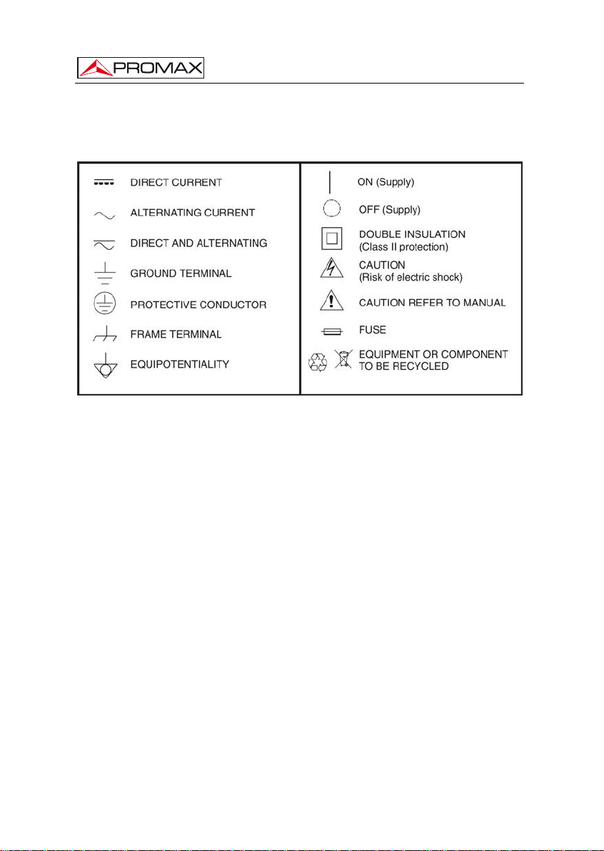
The symbol
may also appear as a Caution or Warning symbol.
Warning and Caution statements may appear in this manual to avoid injury
hazard or damage to this product or other property.
on the equipment means "SEE USER’S MANUAL". In this manual
Page 3

CONTROL MODULE. DT-802
TABLE OF CONTENTS
1. GENERAL..................................................................................................................1
1.1 Description ..........................................................................................................1
1.2 Specifications......................................................................................................2
2. SAFETY RULES........................................................................................................ 5
2.1 General................................................................................................................5
2.2 Descriptive Examples of Over-Voltage Categories.............................................6
3. INSTALLATION .........................................................................................................7
3.1 DT-900 Sub-rack.................................................................................................7
3.2 Instalación de los módulos en el DT-900............................................................9
3.3 Connecting wires.................................................................................................9
3.4 Instruccions for installation................................................................................12
4. INSTRUCTIONS FOR USE.....................................................................................13
4.1 Description of the Controls and Elements.........................................................13
4.2 Arrows and Function Keys Description ............................................................. 14
4.3 LEDs Table........................................................................................................15
4.4 DT-802 Starting Up ...........................................................................................15
4.5 Main Screen......................................................................................................16
4.6 PASSWORD .....................................................................................................18
4.7 CONFIGURATION............................................................................................19
4.7.1 Description of the initial setup screen.........................................................19
4.7.2 Browsing the SETUP menu ........................................................................20
4.7.3 Entering, Editing and Selecting values.......................................................21
4.7.4 DT-802 Configur ation..................................................................................22
4.8.2 PkUpdate....................................................................................................27
5. PRACTICAL EXAMPLES OF SYSTEMS DTTV .....................................................29
6. GLOSSARY OF TERMS ......................................................................................... 33
7. MAINTENANCE.......................................................................................................37
7.1 Cleaning Recommendations.............................................................................37
English
Page 4

CONTROL MODULE. DT-802
Page 5

CONTROL MODULE. DT-802
CONTROL MODULE
DT-802
DIGITAL TV HEADEND
1. GENERAL
1.1 Description
The DTTV system (Digital to TV) is based on a TV headend that receives television
signals from different sources. It processes them for its integration into an output signal in
Digital Terrestrial (DVB-T) format. In this way, the signal can be distributed
network with multiple receivers, keeping the original wiring installation but distributing in
high-quality format. This system is applicable to hotels, hospitals, shopping centres,
universities, etc. that is, local distribution networks that want to distribute media content in
digital quality.
The DT-802 is the control and power module, therefore is the most important
module of the DTTV system. The control modul
headend via modem-cable.
e is connected to all the modules of the
on a TV
The DT-802 allows controlling and configurating each module individually. The user
can manage and
remote mode. In local mode, the module is managed via the keypad and the LCD screen
placed on the frontal of the DT-802. In remote mode, the control module is connected to a
computer through a network cable and it is managed by using the specific software
control.
The difference between the control module DT-800 and
DT-802 is that the DT-802 has a redundant power system based on two totally
independent batteries that can be hot-swapped without affecting the network distribution
system. The redundant battery works when the other battery fails due to a malfunction
or a failure of the supplier. It warns the user using a buzzer and a light.
04-2015 Page 1
check the status of any module in two different ways: in local mode or in
the control module
English
Page 6

CONTROL MODULE. DT-802
1.2 Specifications
MODULE
Control/Supply Up to 7 modules DT-802.
Auto-config Auto-detection of connected modules.
Auto-link Auto-detection of interconnection between
Local interface LCD screen.
COMMUNICATIONS
Ethernet 10/100Mb. Via virtual serial port.
MODULES CONFIGURATION
Local Through local interface.
Remote Through Ethernet port (PC software supplied).
POWER SUPPLY
Network voltage 90 — 250 V AC
Network frequency 50-60 Hz.
Consumption 6 A / 3 A maximum for a range lower / higher at
Output Connector JST B08P-XL-HDS.
Amount 4
Output voltage + 12 V, 14 A max.
+5 V, 20 A max.
OPERATING ENVIRONMENTAL CONDITIONS
Altitude Up to 2000 m.
Temperature range From 5 °C to 40 °C.
Max. Relative humidity 80 % ( 31 °C), decreasing lineally up to 50% to
MECHANICAL FEATURES
Dimensions W. 50 x H. 262 x D. 230 mm.
Weight 1.85 kg.
modules.
Navigation keypad (6 keys).
3x information LEDs: On / Not ready / PSU
Status.
Intuitive Navigation Menu (tree type menu).
the input voltage.
40 °C.
Page 2 04-2015
Page 7

CONTROL MODULE. DT-802
ACCESORIES SUPPLIED
2 x CC005 Mains cord.
1 x CC043 Cable Alim. 3 mod.
1 x CC044 Cable Alim. 4 mod.
1 x CC143 Cable Alim. 350 mm 4 mod (DT-802).
1 x CC144 Cable Alim. 470 mm 4 mod (DT-802).
1 x 0 MI1786 User’s Manual DT-802.
SPARE PARTS
AL-802 1 x Spare Power Supply.
RECOMMENDATIONS ABOUT THE PACKING
It is recommended to keep all the packing material in order to return the
equipment, if necessary, to the Technical Service.
(each control unit DT-802 integrates two sources
AL-802).
English
04-2015 Page 3
Page 8

CONTROL MODULE. DT-802
Page 4 04-2015
Page 9

CONTROL MODULE. DT-802
2. SAFETY RULES
2.1 General
* The safety could not be assured if the instructions for use are not closely
followed.
* Use this equipment connected only to systems with their negative of
measurement connected to ground potential or isolated from the network.
* This is a Class I equipment, for safety reasons plug it to a supply line with the
corresponding ground terminal.
* This equipment can be used in Overvoltage Category II installations and
Pollution Degree 1 environments.
* When using some of the following accessories use only the specified ones to
ensure safety.
* Observe all specified ratings of supply.
* Remember that voltages higher than 70 V DC or 33 V AC rms are dangerous.
* Use this instrument under the specified environmental conditions.
Power cord.
* The user is not allowed to perform changes inside the equipment. Any change
on the equipment must be done exclusively by specialized staff.
* When using the power adaptor, the negative of signal is at ground potential.
* Do not obstruct the ventilation system of the instrument.
* Use appropriate low-level radiation cables for Input / output signals, especially
on high level signals.
* Use remote configuration cables <3m.
* Follow the cleaning instructions described in the Maintenance paragraph.
English
04-2015 Page 5
Page 10
CONTROL MODULE. DT-802
* Symbols related with safety:
2.2 Descriptive Examples of Over-Voltage Categories
Cat I Low voltage installations isolated from the mains.
Cat II Portable domestic installations.
Cat III Fixed domestic installations.
Cat IV Industrial installations.
Page 6 04-2015
Page 11
CONTROL MODULE. DT-802
3. INSTALLATION
3.1 DT-900 Sub-rack
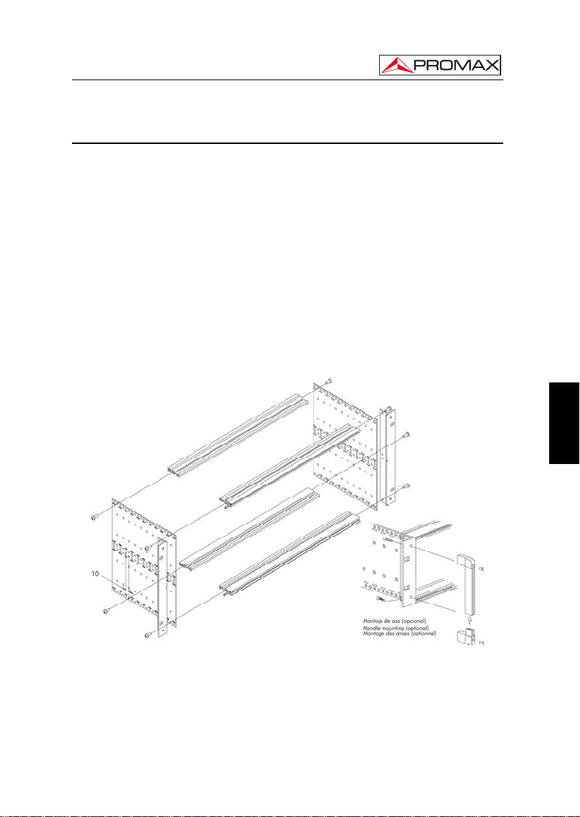
The DT-900 is a metallic casing (sub-rack), where the DTTV modules are
installed (Fig. 1).
Supplied accessories allow the subrack to be set up in two ways: Installing it in a
19 " rack cabinet (Fig. 2) or anchoring it on a wall.
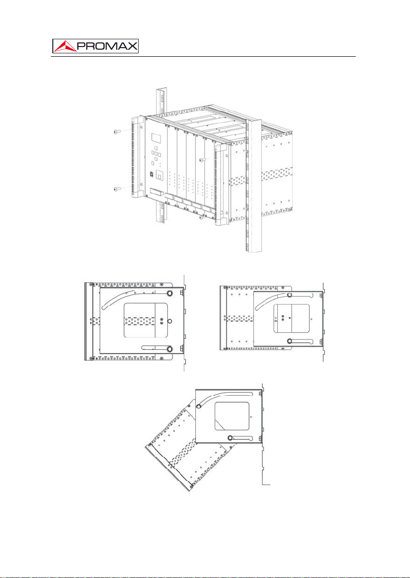
The wall anchoring system allows, through a tilting system, accessing the rear of
the subrack, where the connectors are placed (Fig. 3).
One subrack can contain approximately 8 modules. One of them must be the
control module DT-802.
The sub-rack DT-900 is supplied with an user’s manual, which describes in detail
the steps to complete the assembly.
English
Figure 1.- Subrack Assembly DT-900.
04-2015 Page 7
Page 12
CONTROL MODULE. DT-802
Figure 2.- Assembling a DT-900 in a Rack Cabinet.
Figure 3.- Tilting System.
Page 8 04-2015
Page 13
CONTROL MODULE. DT-802
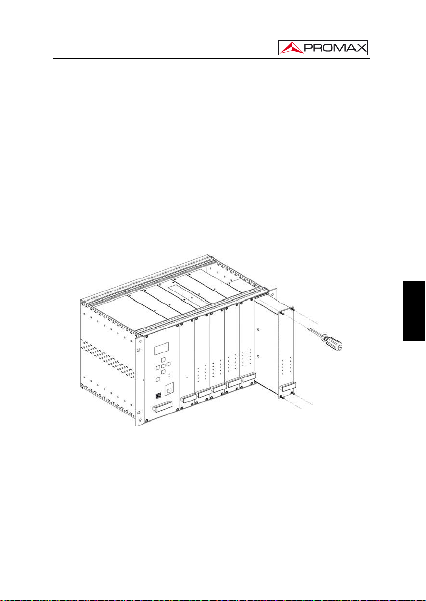
3.2 Installing modules in the DT-900.
To install a module in the subrack, you should slide the module into the subrack,
screwing it to the frontal guide (Fig. 4).
In order to get a tidy installation of the modules you should follow the next
advises:
• Place the DT-802 at the left end of the sub-rack.
• Place the DT-700 and / or DT-710 at the right end of the sub-rack.
• Place the DT-101/102 and the DT-301/302 side by side in the case they were
paired.
• Place the rest of the modules together, without leaving a gap between them.
English
Figure 4.- Installation of the modules into the sub-rack.
Following these advises you will achieve a tidy installation and the best
configuration for later maintenance or new modules addition.
3.3 Connecting wires
The modular composition of the DTTV headend makes it flexible to adapt it to
customer needs.
04-2015 Page 9
Page 14

CONTROL MODULE. DT-802
The DT-802 module has two IEC C14 inlet connector to power directly from the
mains. The DT-802 has four power outputs for the control and power of the rest of
modules. They work equally and can be used for any module. Along with the DT-802
module are supplied the control and power cables.
It does not exist a standard configuration for a DTTV headend. Depending on the
use you want for it, the configuration and position of the modules would change, and
therefore it will change the connection between them. Each module is supplied with
interconnecting cables, which are needed to carry out any possible combination
between modules.
Figure 5.- Application example DTTV.
The wiring must be done when the DT-802 module is off. You do not have to turn
it on until ALL connecting work is done (on one hand control cables between the CPU
and the modules and on the other hand, TS cables between modules). This is because
during the starting up, the CPU scans all the modules, in order to determine the relation
among them. If you turn it on before connecting, you will have to spend additional time
defining the links by hand because the CPU can not detect the connections made in
real time.
Page 10 04-2015
Page 15

CONTROL MODULE. DT-802
If you change connection cables between modulators and receivers, you should
reboot the system so that the CPU will do a new assignment, otherwise you will should
modify assignments manually using the setup menu of the DT-802 module.
If there is any pair of DT-101/102 and DT-301/302 linked, NO place each one in a
different sub-rack controlled by different control modules because it would not work
properly.
English
Figure 6.- Application example DTTV.
The DT-802 has an electric current sensor that prevents it from starting up when it
is not connected to any module. Therefore the control module will not be ON if at least
one connection is made previously.
The combiner modules DT-700 and DT-710 are supplied with some resistors to
balance the inputs/outputs not used and unbalanced. You should also bear in mind that
the module DT-802 does not control these two modules. The DT-700 is also a passive
module combiner that does not need to be powered.
The necessary devices to connect the antenna or signal sources to the headend
(Splitters, cables, connectors, etc.) are not supplied with the DTTV. In the same way, if
you want to combine an output DTTV signal with other signals already existing, such as
DTT, the installer will must provide the necessary connectors.
04-2015 Page 11
Page 16

CONTROL MODULE. DT-802
For an optimal use of the capabilities of the DTTV, it is advisable to use an
universal LNB with independent outputs or an universal LNB with dual polarity (V/H)
and dual band (L/H), both with a switchable splitter for satellite, in order to be able of
distributing simultaneously signals in different bands and polarisations.
It is not advisable to use an universal LNB with only one output and a satellite
splitter because in that case all the modules would be tuned at the same polarisation
(V or H) and band ( L or H).
3.4 Instructions for installation
After identifying the elements that make up a DTTV installation, now we are going
to explain the basic procedure for installing and starting-up:
1. Assemble the DT-900 subrack. Follow the assembling steps described on the
manual supplied with the sub-rack.
2. Depending on your needs and available space, put the subrack on a wall or inside
a rack cabinet.
3. Install the modules inside the subrack and their connecting wires. Follow the
specific instructions provided with each module.
4. Before running the headend you should check that you are receiving input signals
properly (satellite TV, analogue, etc...).
5. Check that all modules are wired properly, especially the power cord from the
control module to the modules and the wiring between them.
6. Start up the system using the switches placed at the rear of your control module.
7. Wait for a few seconds until the control module finishes sweeping and detects all
the modules. After that, all them will receive the default configuration data.
8. Verify that the modules detected by the control module and appearing on the
screen correspond to the ones installed. Also, you should check there is not any
error message on the screen (Note: On one hand, the modules DT-700 and
DT-710 are not detected by the control module and on the other hand, dual
modules appear as two independent units).
9. Set up each module according to your needs.
10. If you have changed the configuration, you should save and restart the control
module in order to apply the changes on the modules.
11. At the end of the process all LEDs should be GREEN or off. If there is any LED in
RED, check the configuration and wiring of each module according to the error
description showed on the screen.
12. Connect the DTTV output to a receiver device, then tune the signal and check
you are receiving the TV programmes and services.
Page 12 04-2015
Page 17

CONTROL MODULE. DT-802
4. INSTRUCTIONS FOR USE
4.1 Description of the Controls and Elements
The only element of control is the DT-802 module. The rest of modules refer to
their status by LEDs place on the front of the module.
Frontal Panel
English
Figure 7.- Panel frontal DT-802.
[1] Display.
[2] Control Keys.
[3] Escape Key.
[4] PSU (Power Supply Unit) status.
[5] Ethernet RJ-45 Connector.
[6] Buzz (Pulsar para apagar el zumbador).
04-2015 Page 13
Page 18

CONTROL MODULE. DT-802
[7] Online LED.
[8] LED NOT READY.
[9] Power Connector (IEC C14).
[10] LED operating.
[11] Power Switch.
[12] LED Failure.
[13] RESET button
[14] Power and Control Output
4.2 Arrows and Function Keys Description
Figure 8.- Function Keys.
Enter the menu / Validate / Select / Deselect.
Go to the upper level menu / Increase a number.
Go to a lower level menu / Decrease a number.
Go to the menu on the right / Go to the number on the right.
Go to the menu on the left / Go to the number on the left.
Exit without validating.
Page 14 04-2015
Page 19

CONTROL MODULE. DT-802
4.3 LEDs Table
The LEDs of each module indicate a certain status depending on the colour.
The LEDs are placed on the front panel of the module.
In the case of a dual module, there will be two columns of LEDs, one per each
module.
Name Status Description
ON
ERROR
TS-IN
DVB-T
PROGRAM
LOCKED
SERVICE LIST
TS-OUT
A/V
MUX
GREEN The module is receiving voltage and working.
OFF Off / Does not work.
GREEN It is working properly.
RED There is an error in the process.
GREEN Transport Stream received correctly.
RED There is a problem in the reception of the
GREEN DVB-T output signal is correct.
RED Problem at the output.
INTERMITTENT GREEN DT-802 is programming the unit.
OFF No programming.
GREEN Locked signal.
RED It was not posible to tune.
GREEN Service List detected.
RED It was not able to read the service list.
GREEN Proper TS output.
RED Problems at the TS output.
GREEN Audio and video processing is working properly.
RED Error during the process / Encoder broke down.
GREEN Proper Multiplexing.
RED Error during multiplexig. / Multiplexer broke down.
Transport Stream (too fast, TS wrong...).
Table 2.-Table of LEDs description.
4.4 DT-802 Starting Up
Turn on your equipment through the switch, which is placed on the rear panel of
the module ( Fig. 7 [11] ).
After starting up, the DT-802 scans the modules connected to it in order to detect
how many and what modules are and if there is any problem.
During the scan, the control module carries out the assignment of bus addresses
and after that an AUTOLINK, which consists in identifying those receivers / modulators
paired (eg DT-301/302 with DT-101/102). This function is essential for a proper
definition of the SERVICES LIST. In order to this assigment works, is necessary to
make the wire connections before starting up. Otherwise you will should made
assigments manually, with the consequent loss of time.
English
04-2015 Page 15
Page 20

CONTROL MODULE. DT-802
The scanning process takes about ten seconds. After it, it displays on the screen
a list of all the modules identified. If the process takes longer, maybe there is a problem
with the wiring or the CPU.
4.5 Main Screen
The main screen shows the list of all the modules identified.
At the top of the screen the text MODULES FOUND indicates the number of
modules detected and below a list with the names of each one of the modules.
If the modules detected are more than four, the list is rotating, that is, it rotates on
a sequential order to show all the elements.
The modules are identified as follows:
DT-XXX-SY-MZ
Where:
XXX Indicates the name of the module.
SY S means SLOT and Y is a number equal to the slot position in the
subrack case. This position is the one the module assigns
automatically every time you turn it on. If it does not correspond to
the actual position can be changed manually, but it does not affect
the operation for practical purposes.
MZ M means MODULE and Z is a number that identifies the receiver or
modulator module (1 for the first module, 2 for the second one).
The bottom of the screen shows the current STATUS of the modules. If
everything is correct it shows the message "OK. PRESS ENTER TO SETUP" (Fig. 9).
Page 16 04-2015
Figure 9.- Main Screen.
Page 21

CONTROL MODULE. DT-802
The automatic position assignment does not have any practical effect. Each time
you restart the DTTV, the control module will assign different positions to each module.
If you do not like this way to assign, Then you can create and save your own assigment.
In this way, your assigment will remain unchanged.
Verify that the modules appearing in the list correspond with the installed and its
status is OK.
Note that dual modules, such as the DT-102 or DT-302, are treated as two
separate units that must be configured independently.
In contrast, the module DT-7XX, will not appear on the list even if they are
installed in the headend.
If there is some problem, it will appear the name of the module in the STATUS
line and in the line below a brief description of the problem (Fig. 10.-).
Figure 10.- Errors in the Main Screen.
If there are more than one module working wrong, the names of these module will
appear sequentially at the bottom of the screen. Next to the name is shown a number
indicating the order of the module for total modules with errors.
If any of the modules is not listed or its status is not OK, check the connections,
especially the control and power cord, which is what connects the control unit with the
modules, and by which is transmitted the power supply and the identification data and
settings.
If the problem persists, adjust the settings or contact our customer service.
If you want to pass to the setup menu, enter the password and press ENTER
.
The system has a “TIME OUT”, which makes the screen again, after a certain
time without touching any keys.
04-2015 Page 17
English
Page 22

CONTROL MODULE. DT-802
4.6 Password
Access to the configuration of the equipment is protected by a password
(PASSWORD) to prevent improper access by unauthorized persons.
After starting up and scanning, press ENTER
key from the frontal equipad in
order to get into the PASSWORD screen.
The default password is "2008".
Figure 11.- Password.
To enter the password follow the steps below to EDIT a NUMERIC value. You
can apply these steps in order to edit any numeric value.
1.- Press ENTER
to get into the PASSWORD option.
2.- Press RIGHT
or LEFT to move among the numbers, from
units to thousands.
3.- If you want to change a number, press UP
to increase or DOWN
to decrease.
4.- Once the value is edited, press ENTER
to confirm the entered
value.
After entering the password and if it is correct, you will access the setup menu.
If the password is not correct, you can make a new attempt.
Page 18 04-2015
Page 23

CONTROL MODULE. DT-802
4.7 CONFIGURATION
After turning on the unit, wait until the checking of all the units connected to the
control unit is done.
After the checking, press ENTER on the frontal equipped to get into the
CONFIGURATION login screen.
After entering the PASSWORD you will access the settings.
From the starting screen, you can select the module you want to access in order
to edit its settings (Fig. 10.-). To do it, use the keys LEFT
among the available modules.
4.7.1 Description of the initial setup screen
or RIGHT to move
At the top of the screen appears "SELECT MODULE” and at the top right corner
a fractional number indicating the position of the currently selected option over the total
amount of menu options.
At the central area of the screen it appears the name of the module (Fig. 12.-), on
the figure is the DT-802 control unit. Note that the system counts the double modules
like two different units and the configurations of them are independent.
At the bottom area, the first line shows the message "LINK TO: ..." and then the
name of a module. This message indicates the modules the unit control is connected to
and have been detected during the scan after starting. The second line shows the
number of modules found, excluding the control unit.
Figure 12.- Initial setup screen.
The first module that appears after entering the CONFIGURATION menu, is the
control unit DT-802. The order of appearance of the rest of modules may vary
depending on the location and connection of the modules at the rack and the automatic
assigment made by the control unit when booting.
English
04-2015 Page 19
Page 24

CONTROL MODULE. DT-802
To get into the available settings of a particular module, press ENTER
the module is displayed on the screen.
Every time you see a display module, the LED program of this module began to
blink.
4.7.2 Browsing the SETUP menu
1.- From the SETUP screen, pressing LEFT
see what modules are available.
2.- When you have the module you want to configure on the screen, press
ENTER
.
3.- Once inside the setup menu, press the Arrow keys LEFT or
RIGHT
to move through the module setup options.
4.- When the menu option you want to access is displayed, press ENTER
or DOWN
5.- An arrow on the left-side of the selected option, means that you are into
the menu (Fig. 13.-). Now you can change the value displayed on the
screen or move to another menu.
or RIGHT you can
when
Figure 13.- Changing a parameter.
Page 20 04-2015
Page 25

CONTROL MODULE. DT-802
4.7.3 Entering, Editing and Selecting values
- Selecting values
In case you want to SELECT a value among the available ones, use the
arrows LEFT
displays the wanted value, press ENTER
- Submenu
In case you access a SUBMENU, you could move through the options
available using the LEFT
option appears and then press ENTER
submenu, press UP
- Numeric Field Editing
In case you have to EDIT the numeric value, follow these steps:
1.- Press ENTER
2.- Use LEFT
3.- To change the value of a number press UP
4.- Once the value is edited, press ENTER
- Editing text field
In case you have to EDIT the text, follow these steps:
or RIGHT to move among them. When the screen
to confirm it and exit.
and RIGHT arrows, until the appropriate
. When you want to leave the
or ESCAPE .
to enter the menu item.
or RIGHT to move among the numbers.
/ DOWN .
to confirm the value.
English
1.- Press ENTER
2.- To the right of the edit text appears one letter and one number. The
number indicates the position of the character is changing. The letter
beside the number indicates the type of character that is being used
( "A" for capital letters, "a" for lowercase letters, "@" for symbols and "1"
for numbers).
04-2015 Page 21
to enter the menu item.
Page 26

CONTROL MODULE. DT-802
. To
3.- To move between characters press the RIGHT or LEFT
delete a character do a long press (1 s) by pressing RIGHT
LEFT
.
or
4.- To change a character press the UP
or DOWN . To vary the
type of character (uppercase and lowercase letters, symbols or
numbers) make a long press (1 s) with the UP
or DOWN
key.
5.- When you are finished editing press ENTER
to validate the text
and exit the menu.
WARNING!
To VALIDAT or UP .
If you press ESCAPE
E a value after changing it you must press ENTER
the value will not be accepted.
For the changes were applied, you must SAVE previously the settings. There are
tw
o different ways to save the settings made:
On one hand you can save your settings
O
n the other hand you can save the settings of all modules at once using the
ALL option, which is on the DT-802 menu.
SAVE
using the SAVE option on each module.
.7.4 DT-802 Configuration
4
The DT-802 is the control
odule of the DTTV. The DT-802 controls the DTTV headend. Two wire-bus connect
m
the c
ontrol module to the remaining modules of the headend. The DT-802 allows the
and power module, and therefore is the most important
control and configuration of each module in a separate way.
Page 22 04-2015
Page 27

CONTROL MODULE. DT-802
Figure 14.- DT-802 configuration.
The first line at the bottom of the screen shows the modules linked to it. The
second line shows the total amount of modules that the control module has detected,
itself excluded.
4.7.4.1 Menu Tree
The diagram attached shows how to access the DT-802 menu setup and the
options available on it.
English
04-2015 Page 23
Page 28

CONTROL MODULE. DT-802
Page 24 04-2015
Figure 15.- Menu tree DT-802.
Page 29

CONTROL MODULE. DT-802
4.7.4.2 Configuration options DT-802.
The options of the menu CONFIGURATION at the module of control DT-802 are:
- Manual Assigment.
If the Auto assigment done automatically by the system when starting does
not match the actual location of the modules in the rack, this option allows you
to change this assigment manually.
1.- Press ENTER
to get into the menu. With RIGHT and LEFT
arrows you can see the correspondence between the current
location assigned (second line) and the modules (third line).
Figure 16.- Manual assignment.
English
2.- Press ENTER
again. The second line is selected (it shows an arrow
next to it) and you can move the third one, which is the name of the
modules, using LEFT
and RIGHT arrows.
Figure 17.- Change of placement module.
04-2015 Page 25
Page 30

CONTROL MODULE. DT-802
3.- Make assigment manually, one by one and press ENTER
4.- When finished press UP
.
.
- ONID Config
- NID Config (Network Identifier Configuration).
- NIT VERSION
It is a private table about information of the Network This menu has two
options: MODE and VERSION NUMBER. When MANUAL mode is selected
then the version number of the NIT table chosen at the menu VERSION
NUMBER by the user is fixed. When AUTO mode is selected then the
version of the NIT table increments as the contents of the NIT changes.
- Network Name
It allows you to assign a name to the distribution network. It is a text field.
- LCN Config (Logical Channel Number Configuration).
It allows you to change the logical channel number. This is the number from
which programmes are stored in the TV receiver. It is a numeric field.
- Private Data Specifier
- Ethernet Config.
It allows you to modify the parameters of connection to the data network. It
contains a sub-menu with some options to define the parameters of the
network: IP address, mask and gateway. All these fields are numeric.
- Display Contrast.
It allows you to change the display contrast of the control module among
these values: Low , Medium and High.
- Language
It allows you to select the language displayed on the configuration menu
(English or French).
Page 26 04-2015
Page 31

CONTROL MODULE. DT-802
- Save All Modules.
It saves all changes made and validated of all the modules. After entering,
press ENTER
ATTENTION!
to confirm you want to save your changes.
If you do not save these changes will be lost when you turn off the control
module!
- About.
It is an information option. It shows technical information of all the modules, as the
firmware version or the IPN (Identifier Product Number). Press ENTER and then left or
right to see information of all the modules.
4.8.2 PkUpdate
The program PkUpdate allows you to update the firmware your headend DTTV.
In the case of new versions of firmware, you will need this program PkUpdate to
transfer the update file from your computer to the DTTV microprocessor.
Steps to follow:
1.- Install the software PkUpdate on your computer. Double-click on the
executable located in the folder "PkUpdate" which is in the CD supplied
with the unit DT-802.
2.- Once installed, run the program from the icon
PkUpdate.lnk
PkUpdate that
has been created on the desktop. Previously, make sure the computer is
connected to the module DT-802.
3.- Click on the shortcut icon "Load Update configuration file" and
through the browser window that opens, find the updating file that you
should have been previously downloaded.
4.- Click on the updating file and press "Open."
5.- Use the key "MODEL" in order the program detects the
DT-802 module. If it does not comunícate then check the communication
parameters by pressing the setup key
. Check also the cable
network is working properly.
English
04-2015 Page 27
Page 32

CONTROL MODULE. DT-802
6.- Use the button "Update" to begin the process. The
updating progress can be watch through the status bar.
7.- The time took by the process is relative. It is depends on the size file and
the number of units to update.
8.- The program will update all units of the same type in the head end, that is,
if the firmware affects units DT-30X, and there are more than one in the
head end, they all will be updated.
9.- When the progress bar reaches 100%, it pops-up a window with the
message box "Update process successful".
10.- Once the process is finished, quit the program and restart the module
DT-802.
For more details please, read the manual that is supplied with the CD or visit our
website:
Page 28 04-2015
Page 33

CONTROL MODULE. DT-802
5. PRACTICAL EXAMPLES OF SYSTEMS DTTV
The owner of a hotel in Menorca, Mr. Ferrer, wants to give the hotel a touch of
distinction over the competition, so he has decided to install flat TV screens with built in
DTT tuner in each room and a satellite dish. He wants an installation of digital quality,
but without spending too much money and using the analog distribution network already
installed. He also wants to add some international channels to the TV services, in
addition to the national ones already available, because often there are Italian and
German customers. How can the system DTTV fulfill his wishes? Read next...
1.- Current infrastructure.
Firstly, it should be clear to you the purpose of your installation and the
existing telecommunications infrastructure in your establishment. In this
specific case:
- Analogue TV Distribution network via coaxial cable.
- DTT receivers with built-in tuner.
- Satellite dish.
- Terrestrial antenna receiving digital and analogue signal.
2.- TV Services to distribute.
You should decide what channels and services you want to distribute at your
hotel. In this specific case:
- All national DTT channels.
- Two Italian satellite channels (Canale 50 and TV7 Lombardia).
- Two German satellite channels (Das Erste and RTL 2 Schweiz).
3.- With these initial data, you can get an idea of what you need for your DTTV
installation.
- To tune 2 channels of different frequencies, you need a dual receiver,
therefore, use a DT-302.
- To convert 2 signals to digital, you need a DT-102.
- To combine the resulting signals and obtain a single output, you need a
combiner DT-710.
English
04-2015 Page 29
Page 34

4.- Translating the installation to a diagram block:
Figure 18.-
And the electrical connections scheme.
CONTROL MODULE. DT-802
Figure 19 .-
5.- Search data for the tuning of the channels and services.
The tuning data for the channel where are the Italian services "Canale 50”
and “TV7 Lombardia” are:
Page 30 04-2015
Page 35

CONTROL MODULE. DT-802
Frequency: 11.541.
Polarization: Vertical.
Symbol Rate: 22000.
FEC: 5 / 6.
Standard: DVB-S QPSK.
The tuning data for the channel where are the German services “Das Erste” y
“RTL 2 Schweiz” are:
Frequency: 11,604.
Polarization: Horizontal.
Symbol Rate: 22000.
FEC: 5/6.
Standard: DVB-S QPSK.
6.- After obtaining the data, the DT-302 dual module is configured in order to
tune the channels selected. Turn on the ⎧ and enter, step by step, all the
settings. Due to it is a dual module, each unit has to be set separately.
Receiver 1:
LNB Local Oscillator: According to the data collected, it is a vertical
polarization. Therefore is 9750 MHz.
DL-Frequency: 11,541.
DL-Band: For the European area is Ku-band.
LNB: For vertical polarization, 13V.
Standard: It is a normal digital channel, therefore DVB-S.
Symbol Rate: 22000.
Service List: Select the services: "Channel 50" and "TV7 Lombardia
(Although it has capacity for many more).
Receiver 2:
LNB Local Oscillator: This is a horizontal polarization. It is therefore
10,600 MHz
DL-Frequency: 11,604.
DL-Band: For the European area is Banda C.
LNB: For horizontal polarization, 18V.
Standard: This is a normal channel of digital quality, it's DVB-S.
Symbol Rate: 22,000
Service List: Select the services "Das Erste" and "RTL 2 Schweiz."
(Although it has capacity for many more).
English
04-2015 Page 31
Page 36

CONTROL MODULE. DT-802
7.- Once set the DT-302, you should set the DT-102 in order to adjust the output
frequency of the channel.
8.- The output signals of the DT-102 is the combination of the two inputs from the
DT-302, therefore you will get a single RF output with services of the German
and Italian channels. Now only rests to mix it with the DTT signal from the
national broadcasters.
9.- The DT-710 is used to combine the signal from the DT-302 and the DTT
signal. The combiner mixes both two and get the result.
10.- Now it only rests to connect the resultant signal to the TV distribution network
and tune all the TV sets with the new services.
Figure 20 .-
After a few months, Mr. Ferrer is very pleased. German and Italian clients
appreciate having channels in their own language at the hotel, and they feel more
comfortable. The number of bookings has been increased. In addition, few days ago
french customers started to call, asking for information, references and about services
in the hotel, and those include televisión services. And even currently there is no French
channel service, he knows that he can easily set the headend to accommodate new
channels, using the remote control software. After hang up, Mr. Ferrer congratulates
himself for having invested in the installation of the DTTV system.
Page 32 04-2015
Page 37

CONTROL MODULE. DT-802
6. GLOSSARY OF TERMS
MODULATOR: In telecommunications, the modulation is the process of varying a
QPSK: Phase-shift keying (PSK) is a digital modulation scheme that
MULTIPLEXER: In the field of telecommunications, the multiplexer is a device that
periodic waveform, i.e. a tone, in order to use that signal to convey
a message. Normally a high-frequency sinusoid waveform is used
as carrier signal. The three key parameters of a sine wave are its
amplitude ("volume"), its phase ("timing") and its frequency ("pitch"),
all of which can be modified in accordance with a low frequency
information signal to obtain the modulated signal. A device that
performs modulation is known as a modulator and a device that
performs the inverse operation of modulation is known as a
demodulator (sometimes detector or demod). A device that can do
both operations is a modem (short for "Modulator-Demodulator").
conveys data by changing, or modulating, the phase of a reference
signal (the carrier wave). Any digital modulation scheme uses a
finite number of distinct signals to represent digital data. PSK uses
a finite number of phases, each assigned a unique pattern of binary
bits. Usually, each phase encodes an equal number of bits. Each
pattern of bits forms the symbol that is represented by the particular
phase. The demodulator, which is designed specifically for the
symbol-set used by the modulator, determines the phase of the
received signal and maps it back to the symbol it represents, thus
recovering the original data. This requires the receiver to be able to
compare the phase of the received signal to a reference signal –
such a system is termed coherent (and referred to as CPSK).
Depending on the number of possible phases to take, are given
different names. The most common is to codify a number of bits per
symbol, then the number of phases to take is equal to an number
which is a power of two. In the case of QPSK (Quadrature PhaseShift Keying), uses four phases, displaced each other 90 degrees.
Normally are used as a phase jumping values 45 degrees, 135
degrees, 225 degrees and 315 º. Each symbol gives 2 bits. The
constellation diagram shows 4 symbols equally distributed.
can receive and transmit multiple inputs by a shared transmission
medium. To do this it divides the transmission medium into multiple
channels, so that several nodes can communicate simultaneously.
A signal that is multiplexed must be de-multiplexed at the other end.
There are several types of multiplexing depending on how it is
performed this division of the transmission medium: frequency
division multiplexing, time division multiplexing, code division
multiplexing and wavelength division multiplexing.
English
04-2015 Page 33
Page 38

CONTROL MODULE. DT-802
COFDM: Coded Orthogonal Frequency Division Multiplexing is the
modulation system used in the radio and televisión systems. Unlike
other systems that modulate in a single carrier frequency with a
very high rate of symbols, COFDM modulates information in many
carrier frequencies, where each one has a very low rate of symbols.
MPEG-2: Moving Pictures Experts Group 2 (MPEG-2) is the designation for a
set of standards for encoding audio and video agree by MPEG (a
group of experts in moving images), and published as a ISO 13818
standard. MPEG-2 is usually used to encode audio and video for
transmisión signals, including digital terrestrial television, by satellite
or cable. With some modifications, is also the encoding format used
by DVD `s commercial films.
DVB-T: DVB-T is an abbreviation for Digital Video Broadcasting Terrestrial;
it is the DVB European-based consortium standard for the
broadcast transmission of digital terrestrial television. This system
transmits compressed digital audio, video and other data in an
MPEG transport stream, using COFDM modulation.
DVB-S: Digital Video Broadcasting by Satellite (DVB-S) is a system that
allows increasing the transmission capacity of digital television and
data via satellite using MPEG2 format. The structure allows mixing
in a stream a large number of video services, audio and data. For
transmissions via satellite the QPSK encoding is adopted, with a
binary variable flow from 18.4 to 48.4 Mbits / s. DVB-S format is
widely used in European countries.
TS-ASI: (Transport Stream - Asynchronous Serial Interface): It is a protocol
especially designed for transmitting in media sensitive to noise and
used in the DVB standard (Digital TV distribution protocol) for the
transmission of compressed digital television signals. It is also used
as an interface of input and / or output multiplexers, MPEG-2
encoders, etc. ASI interface was created especially for transporting
MPEG transport streams, is extremely flexible and can carry data at
any speed from zero to over 200 Mbit / s.
LNB: The Low Noise Block amplifier or LNB is a device consisting of a
low noise amplifier and a frequency converter (RF to IF). The
reason for use a universal LNB is motivated because it can get all
the bandwidth (the low-band, from 10.7 to 11.7 GHz, and the highband, from 11.7 to 12.75 GHz). This allows the reception of all
analogue channels with an analog receiver, and all digital channels
with a digital satellite receiver. The universal LNB selects the lowband or the high-band, when activating a tone switch of 22 kHz
generated by the digital receiver. Horizontal and vertical polarization
is selected by applying 13 or 18 volt to the power supply.
Page 34 04-2015
Page 39

CONTROL MODULE. DT-802
MER: It is the Modulation Error Rate. It is a measure that allows knowing
how good a modulated digital signal is. It is the equivalent of the
information provided by the signal/noise rate in the analog
modulations.
DL-FREQUENCY: It is the downlink frequency from a satellite to the Earth. It is
equivalent to adding local oscillator frequency plus intermediate
frequency of a signal.
SYMBOL RATE: In digital communications, symbol rate, also known as baud or
modulation rate; is the number of symbol changes (signalling
events) made to the transmission medium per second using a
digitally modulated signal or a line code. The Symbol rate is
measured in baud (Bd) or symbols/second. In the case of a line
code, the symbol rate is the pulse rate in pulses/second. Each
symbol can represent or convey one or several bit of data. The
symbol rate is related to but should not be confused with gross
bitrate expressed in bit/s. A symbol is a state or significant condition
of a channel of communication that persists for a period of time.
The transmiter instrument puts the symbols in the channel at a
known rate of symbols, and the receiving device has to identify the
sequence of symbols in order to rebuild the data transmitted.
NID:
LCN: It a number that identifies the Logical channel number.
PID: It is the Packet IDentification, a number that identifies a service of a
program.
CAM: A conditional access module (CAM) is an electronic device, usually
incorporating a slot for a smart card, which equips an Integrated
Digital Television or set-top box with the appropriate hardware
facility. This enables you to view conditional access content that
has been encrypted using a conditional access system. There is not
an unique CAM that allows working with all the existing formats
encrypted, it depends on the system of encrypted digital platform
you are using.
English
04-2015 Page 35
Page 40

CONTROL MODULE. DT-802
FIRMWARE: Firmware is a term sometimes used to denote the fixed, usually
rather small, programs that internally control various electronic
devices. Typical examples range from end user products such as
remote controls or calculators, via computer parts and devices like
harddisks, keyboards, TFT screens or memory cards, all the way to
scientific instrumentation and industrial robotics. Also more complex
consumer devices, such as mobile phones, digital cameras,
synthesisers, etc., contain firmware to enable the device's basic
operation as well as implementing higher level functions.
TID: The information, in accordance with the MPEG format, is divided
into several packets that are transmitted. Each of these packets
have the same table TID or identification table in order to be
subsequently identified by the receiver.
Page 36 04-2015
Page 41

CONTROL MODULE. DT-802
7. MAINTENANCE
7.1 Cleaning Recommendations
To clean the cover, take care the instrument is disconnected.
CAUTION
CAUTION
Do not use scented hydrocarbons or chlorized solvents. Such products may
attack the plastics used in the construction of the cover.
The cover should
water applied with a soft cloth.
Dry thoroughly before using the system again.
Do not use for the cleaning of the front panel and particularly the viewfinders,
alcohol or its derivatives, these products can attack
materials and diminish their useful time of life.
be cleaned by means of a light solution of detergent and
the mechanical properties of the
CAUTION
English
04-2015 Page 37
Page 42

PROMAX ELECTRONICA, S. L.
 Loading...