

Page 1

AE-366B
SPECTRUM ANALYSER
- 0 MI2007 -
Page 2

MULTIMEDIA CONTENT
You can access instantly to any chapter by clicking on the title of the chapter in the
table of contents.
Click on the arrow
at the top right of the page to return to the table of contents.
USER'S MANUAL VERSION
Version Date Software Version
1.2 July 2018 1.09 14.04.01
Page 3

SAFETY RULES
This chapter contains important safety instructions that you must follow during
operation and storage. Read the following before any operation to insure your
safety and to keep the instrument in the best possible condition.
Safety Guideline
• General
* Do not place any heavy object on the instrument.
* Avoid severe impact or rough handling that leads to damaging the
instrument.
* Do not discharge static electricity to the instrument.
* Use only mating connectors, not bare wires, for the terminals.
* Ensure signals to the RF input do not exceed +30dBm/±25V DC.·
* Do not block the cooling fan opening.
* Do not disassemble the instrument unless you are qualified.
* (Measurement categories) EN 61010-1:2010 specifies the measurement
categories and their requirements as follows. The instrument falls under
category II.
• Power Supply
* AC Input voltage range: 100V~240V.
* Frequency: 50/60Hz.
* To avoid electrical shock connect the protective grounding conductor of the
AC power cord to an earth ground.
• Cleaning
* Disconnect the power cord before cleaning.
* Use a soft cloth dampened in a solution of mild detergent and water. Do not
spray any liquid.
* Do not use chemicals containing harsh material such as benzene, toluene
and acetone.
• Operation Environment
* Location: Indoor, no direct sunlight, dust free, almost non-conductive
pollution (Note below).
Page 4

* Temperature: 5 °C to 45 °C.
* Humidity: 90 % to 45 °C.
* (Pollution Degree) EN 61010-1:2010 specifies the pollution degrees and
their requirement as follows. The instrument falls degree II.
• Storage environment
* Location: Indoor.
* Temperature: 90 % to 45 °C.
• Disposal
* Do not dispose this instrument as unsorted municipal waste. Please use a
separate collection facility or contact the supplier from which this instrument
was purchased. Please make sure discarded electrical waste is properly
recycled to reduce environmental impact.
• Symbols related with safety:
• Descriptive Examples of Over-Voltage Categories
Cat I Low voltage installations isolated from the mains.
Cat II Portable domestic installations.
Cat III Fixed domestic installations.
Cat IV Industrial installations.
Page 5

July 2018
TABLE OF CONTENTS
1 INTRODUCTION........................................................................................ 1-1
1.1 Description .................................................................................... 1-1
1.2 Main Features ................................................................................ 1-1
1.3 Package Content ............................................................................ 1-2
2 GETTING STARTED.................................................................................... 2-3
2.1 Appearance ................................................................................... 2-3
2.2 First Time Use Instructions .............................................................. 2-8
2.2.1 Tilting the Stand ......................................................................... 2-8
2.2.2 Power UP and Down .................................................................... 2-9
2.2.3 Software Update ......................................................................... 2-9
2.2.4 USB Driver Installation ...............................................................2-10
2.3 Restoring Default Settings ..............................................................2-11
2.4 Conventions..................................................................................2-12
3 BASIC OPERATION...................................................................................3-15
3.1 Frequency Settings ........................................................................ 3-15
3.1.1 Center Frequency ......................................................................3-15
3.1.2 Start and Stop Frequency ...........................................................3-15
3.1.3 Center Frequency Step ...............................................................3-16
3.2 Span Settings ...............................................................................3-18
3.2.1 Span........................................................................................3-18
3.2.2 Full Span ..................................................................................3-18
3.2.3 Zero Span................................................................................. 3-19
3.2.4 Last Span .................................................................................3-19
3.3 Amplitude Settings ........................................................................3-20
3.3.1 Reference Level .........................................................................3-20
3.3.2 Amplitude Units ......................................................................... 3-21
3.3.3 Scale/Div..................................................................................3-21
3.4 Autoset ........................................................................................3-22
3.4.1 Using Autoset ............................................................................ 3-22
3.4.2 Limiting the Autoset Vertical Search Range....................................3-23
3.4.3 Limiting the Autoset Horizontal Search Range ................................3-23
3.5 Marker .........................................................................................3-24
3.5.1 Activating a Marker ....................................................................3-25
3.5.1.1 Activate a Normal Marker.........................................................3-25
3.5.1.2 Activate a Delta Marker ...........................................................3-26
3.5.1.3 Move Marker Manually.............................................................3-27
3.5.1.4 Move Marker to Preset Locations...............................................3-27
3.5.2 Move marker to Trace ................................................................3-28
3.5.2.1 Turn All Markers On or Off .......................................................3-29
3.5.3 Show Markers in Table................................................................3-29
3.5.3.1 Edit Markers in Marker Table ....................................................3-30
3.5.4 Peak Search ..............................................................................3-31
3.5.4.1 Move Marker to Peak............................................................... 3-31
3.5.4.2 Move Marker and Peak to Center...............................................3-31
3.5.4.3 Search for Peaks ....................................................................3-32
Page 6

1-2
July 2018
3.5.5 Peak Table ................................................................................3-33
3.6 Measurement ................................................................................3-35
3.6.1 Channel Analysis Overview..........................................................3-35
3.6.1.1 ACPR ....................................................................................3-36
3.6.1.2 OCBW ...................................................................................3-39
3.7 Limit Line Testing ..........................................................................3-41
3.7.1 Activate a Limit Line ...................................................................3-41
3.7.2 Creating a Limit (Point by Point) ..................................................3-42
3.7.2.1 Pass/Fail Testing.....................................................................3-43
3.8 Bandwidth .................................................................................... 3-45
3.8.1 Resolution Bandwidth Setting (RBW) ............................................3-45
3.9 Trace ...........................................................................................3-46
3.9.1 Selecting a Trace .......................................................................3-46
3.9.2 Trace Math ............................................................................... 3-48
3.9.3 Average Trace ...........................................................................3-48
3.10 Display.........................................................................................3-50
3.10.1 Adjusting the LCD Brightness ......................................................3-50
3.10.2 Setting a Display Line (Reference Level Line).................................3-50
3.10.3 Using the Video Out Port.............................................................3-51
3.10.4 Split Spectrum View...................................................................3-51
3.11 Save/Recall Files ...........................................................................3-53
3.11.1 Save/Recall Setup...................................................................... 3-53
3.11.2 Save/Recall Trace Data...............................................................3-54
3.11.3 Save/Recall Limit Lines...............................................................3-55
3.11.4 Saving an Image File (Hardcopy) .................................................3-55
3.11.5 Hardcopy Setup.........................................................................3-56
3.11.6 Load Default Settings .................................................................3-56
3.12 System Settings ............................................................................3-57
3.12.1 System Information ...................................................................3-57
3.12.2 System Language ......................................................................3-58
4 REMOTE CONTROL ...................................................................................4-59
4.1 Interface Configuration...................................................................4-59
4.1.1 Configure Remote Interface.........................................................4-59
4.1.2 Remote Control Function Check ...................................................4-60
4.2 Command Syntax ..........................................................................4-61
4.3 Command List...............................................................................4-63
4.3.1 IEEE488.2 Standard Commands...................................................4-63
4.3.2 Sweep Commands .....................................................................4-63
4.3.3 Frequency Commands ................................................................4-63
4.3.4 Span Commands .......................................................................4-64
4.3.5 Amplitude Commands.................................................................4-65
4.3.6 Marker and Peak Search Commands .............................................4-65
4.3.7 Trace Commands .......................................................................4-68
4.3.8 Power Measurement Commands ..................................................4-69
4.3.9 Limit Line Commands .................................................................4-71
Page 7

July 2018
4.3.10 BW Commands..........................................................................4-71
4.3.11 Display Commands ....................................................................4-72
4.3.12 Preset Commands......................................................................4-73
4.3.13 System Commands ....................................................................4-73
5 FAQ .......................................................................................................5-74
6 SPECIFICATIONS .....................................................................................6-75
6.1 Specifications AE-366B...................................................................6-75
6.2 Default Settings ............................................................................ 6-77
Page 8

Page 9

July 2018 1-1
SPECTRUM ANALYSER
AE-366B
1 INTRODUCTION
1.1 Description
The AE-366B is a low-cost, basic spectrum analyzer. The AE-366B has all
the basic features of our more advanced models, but in a smaller package,
designed especially for education.
Figure 1.
1.2 Main Features
► Performance:
150 kHz ∼ 3 GHz.
100 kHz resolution.
► Features:
Autoset with automatic floor level and span.
Marker table function.
Limit line testing.
Split window display.
Page 10

ACPR measurement.
OCBW measurement.
Automatic resolution bandwidth mode.
► Interface:
480 × 640 color LCD display.
On-screen menu icons.
VGA video output.
RS-232C.
USB 2.0 Host port for data storage.
USB 2.0 Device port for the virtual com port communication.
1.3
Package Content
Opening the box
Figure 2.
Check that your package contains the following elements:
AE-366B Analyser.
Quick Start Guide.
Mains cord for external DC charger.
1-2
July 2018
Page 11

July 2018 2-3
2 GETTING STARTED
2.1 Appearance
Front Panel
Figure 3.
► LCD display:
640 X 480 color LCD display. The display shows the soft keys for the current
function, frequency, amplitude and marker information.
► Function keys:
The
to function keys directly correspond to the soft keys on the right-
hand side of display.
► Menu keys:
Frequency:
Sets the center frequency, start frequency,
stop frequency and step frequency.
Span:
Sets the span, with options for full span,
zero span and last span.
Page 12

Amplitude:
Sets the amplitude reference level, scale
and amplitude units.
Autoset:
Automatically searches the peak signal with
maximum amplitude and displays it with
appropriate horizontal and vertical scales.
Marker:
The Marker key is used to configure the
markers, trace markers as well as other
related functionality.
Peak
Search:
Finds each maximum and minimum peak.
Used with the Marker functions.
Meas:
Configures ACPR and OCBW measurements.
Limit Line:
Sets and tests Pass/Fail limit lines.
BW:
Sets the resolution bandwidth.
Trace:
Sets traces and trace related functions.
Display:
The Display key configures the split-screen
windowing mode and the basic display
properties.
Memory:
The memory key is used to save or recall
setup, trace and limit line data.
Preset:
T
he Preset key will restore the spectrum
analyzer to the factory settings.
Hardcopy:
T
he hardcopy key is a quick save key that
will save a screen-shot of the display.
Hardcopy
setup:
Configures the hardcopy options.
System:
T
he System key is used to configure the
RS232 interface, language, update the
firmware as well as other system options.
2-4
July 2018
Page 13

July 2018 2-5
► Power key:
Turns the instrument on/off.
► Scroll wheel:
Edit values, select listed items.
► Arrow keys:
Increment/decrement values (in steps),
select listed items.
► RF input
terminal:
RF input port. Accepts RF inputs.
Maximum input: +30 dBm (+20 dBm
measurable).
Input impedance: 50 Ω.
Maximum DC voltage: ±25 V.
N-type: female.
► Numeric
keypad:
T
he numeric keypad is used to enter vales
and parameters. It is often used in
conjunction with the arrow keys and scroll
wheel.
Page 14

Rear Panel
Figure 4.
► RS-232:
RS232 9 pin DSUB port.
► USB B:
USB B Device port. USB 1.1/2.0.
► VGA:
VGA video-out port. Supports SVGA
(480X640).
► Power Socket:
Power Socket:100~240V, 50/60Hz.
15W Max.
► Security Slot:
Kensington-type security slot.
2-6
July 2018
Page 15

July 2018 2-7
Display
Figure 5.
► Reference level:
Displays the reference level.
► Marker Information:
Displays marker information.
► Function menu:
Displays the current function menu.
► Soft menu keys:
The Soft menu keys are associated with the F1 to F6 function keys to the right
of the display.
► Trace Icons:
Displays the color of each active trace and the trace mode of each active
trace.
► Entry/Message area:
This area is used to show system messages, errors and input
values/parameters.
► Frequency/Bandwidth settings:
Displays the Start, Center and Stop frequencies, RBW, Span and Sweep
settings.
Page 16

► Trace and waveforms:
Main display showing the traces, limit lines and marker positions.
2.2 First Time Use Instructions
Use the procedures below when first using the AE-366B to tilt the stand, power
up the instrument, update the firmware and restore the unit back to the default
settings. Lastly, the Conventions sections will introduce you to the basic
operating conventions used throughout the user manual.
2.2.1
Tilting the Stand
The AE-366B has two adjustable tabs at the front that can be used to position
the instrument into two preset orientations.
► Leaning Position:
Set the tabs down to have the AE-366B leaning backward.
Figure 6.
► Upright Position:
Set the tabs flat to have the AE-366B in an upright position.
Figure 7.
2-8
July 2018
Page 17

July 2018 2-9
2.2.2
Power UP and Down
► Power UP:
Insert the AC power cord into the power socket.
Figure 8.
Press the power button to turn the AE-366B on.
Figure 9.
The AE-366B will begin to boot up in under a few seconds.
NOTE: If system fails to start, please see your local PROMAX distributor.
► Power Down:
Press the power button to power down.
Figure 10.
2.2.3
Software Update
The AE-366B allows the software to be updated by end-users. Before using the
AE-366B, please check the PROMAX website or ask your local distributor for the
latest software.
The update file, MAIN1.BIN, must be placed in the root directory of a USB flash
drive.
► System version:
Before updating the software, please check the software version.
Press
X
Information .
Page 18

The system version is displayed on the SW Ver icon.
Figure 11.
► Update software:
Before updating the software, please check the software version.
Place the update file, MAIN1.BIN, into the root directory of a USB flash
drive.
Insert the USB flash drive into the USB port on the front panel.
Press
X Update From USB Flash
.
Press Update Now to execute the update process.
When the message “Programmed Successful” is displayed, the software
has successfully completed the update procedure.
Reboot the system when the update procedure has finished by cycling
the power button.
Check the software version again to confirm the update procedure.
NOTE: The upgrade process may take a few minutes.
2.2.4
USB Driver Installation
If the type B USB port on the rear panel is to be used for remote control, then
the USB driver must be installed.
Ensure the AE-366B is turned on.
Connect the USB cable from the PC to the rear panel USB B port.
Windows will automatically detect the AE-366B as a new device.
2-10
July 2018
Page 19

July 2018 2-11
Follow the instructions to locate the AE-366B driver.
To see if the driver has been successfully installed, you can check to see
if the AE-366B is recognized by the Windows Device Manager when the
AE-366B in connected to the PC.
In Windows XP go to: Start X Control Panel X Device Manager.
The AE-366B should be shown under the Ports (COM & LPT) node:
Figure 12.
NOTE: If the USB driver installation fails, you can try to manually install the
driver.
You can tell that the driver hasn’t been installed if you see the
USBSerial icon in the ports node.
Right clicking this icon will allow you to manually install the AE-366B.ini
driver.
2.3 Restoring Default Settings
The factory default settings can be easily restored using the Preset key on the
front panel. The default settings cannot be changed.
Press .
(The spectrum analyzer will load the default factory settings).
Page 20

2.4 Conventions
The following conventions are used throughout the user manual. Read the
conventions below for a basic grasp of how to operate the AE-366B menu
system and front panel keys.
► Soft Menu keys:
The to function keys on the right side of the display correspond
directly to the soft-menu keys on their left.
Figure 13.
► Input Parameter
Values:
Selecting this type of menu key will allow
you to enter a new value with the numeric
keypad or increment/decrement the value
using the scroll wheel or number pad. See
the parameter input description below for
more details.
► Toggle State:
Pressing this menu key will toggle the
state. Notice that any soft-menu key that
can be toggled will have the active
parameter underlined.
► Toggle State &
Input Parameter:
Pressing this menu key will allow you to
toggle the state of the function between
on and off. When in the on-state, the
parameter value can be manually edited.
Use the numeric keypad to enter the new
value or use the scroll wheel to
increment/decrement the current value.
Again, the setting that is underlined is the
active setting.
► Sub Menu:
Pressing the More menu key will enter a
submenu.
► Sub Menu to select
parameter:
Pressing this type of menu key will enter a
submenu to select a parameter.
2-12
July 2018
Page 21

July 2018 2-13
► Return to the Start
of a Menu Tree:
When you have navigated down a menu
tree and you wish to return to the start of
the menu tree, simply press the same
Menu again.
For example if you pressed:
X More X Min Hold ,
simply press
again to return to
the start of the Trace menu.
► Active Function:
Pressing this type of menu key will
activate that function. The menu key will
be highlighted to show it is the active
function.
► Parameter input:
Figure 14.
Parameter values can be entered using the numeric keypad, the scroll wheel
and the arrow keys.
Using the numeric keypad:
When prompted to enter a parameter, use the number keys (0 ~ 9), the
decimal key (.) and the minus key (-) to enter a value. After a value has
been entered, the unit keys can be used to select the units.
Page 22

The value of the parameter is shown at the bottom of the screen as it is
edited.
Figure 15.
Back Space:
Use the backspace key to delete the last character or number entered.
Using the scroll wheel:
Use the scroll wheel to alter the current value. Clockwise increases the
value, anti-clockwise decreases the value. The scroll wheel is usually used
for values that highly variable, such as the center frequency settings.
Directional arrows:
Use the directional arrows to select discrete parameters or to alter values
by a coarser resolution than the scroll wheel. Left/down decreases the
value, right/up increases the value. The directional arrows are usually
used for values that are of a discrete nature, such as selecting a memory
location.
2-14
July 2018
Page 23

July 2018 3-15
3 BASIC OPERATION
3.1 Frequency Settings
3.1.1
Center Frequency
The center frequency function sets the center frequency and centers the display
to the center frequency.
Press
X Center and enter the frequency and unit.
Range 0 kHz ~ 3 GHz
Default: 1.5 GHz.
Figure 16.
3.1.2
Start and Stop Frequency
The start/stop frequency function will set the start and stop frequency of the
span.
To set the start frequency, press
X Start and enter the
frequency and unit.
Page 24

To set the stop frequency, press X Stop and enter the
frequency and unit.
Range: 0 kHz ~ 3 GHz.
Default Start frequency: 0 Hz.
Default Stop frequency: 3 GHz.
Figure 17.
NOTE: The start and stop frequency can change when the span settings are
used.
The stop frequency must be set higher than the start frequency
(for spans ≠ 0).
3.1.3
Center Frequency Step
The Step function sets the step size of the center frequency when using the
arrow keys.
When the arrow keys are used to alter the center frequency, each press will
move the center frequency by the step size specified by the Step function.
3-16
July 2018
Page 25

July 2018 3-17
By default, the center frequency step size is equal to 10% of the span.
Press
X Step and set the center frequency step size.
Range: 1 kHz ~ 3 GHz.
Figure 18.
Page 26

3.2 Span Settings
3.2.1
Span
The Span function will set the frequency range of the sweep. The sweep will be
centered around the center frequency.
Setting the span will alter the start and stop frequencies.
Press
X Span and enter the span frequency range and
unit.
Range: 0 kHz ~ 3 GHz.
Default Span: 3 GHz.
Figure 19.
3.2.2
Full Span
The Full Span function will set the span to the full frequency range.
This function will set the start and stop frequencies to 0 Hz and 3 GHz
respectively.
Press
X Full Span .
3-18
July 2018
Page 27
July 2018 3-19
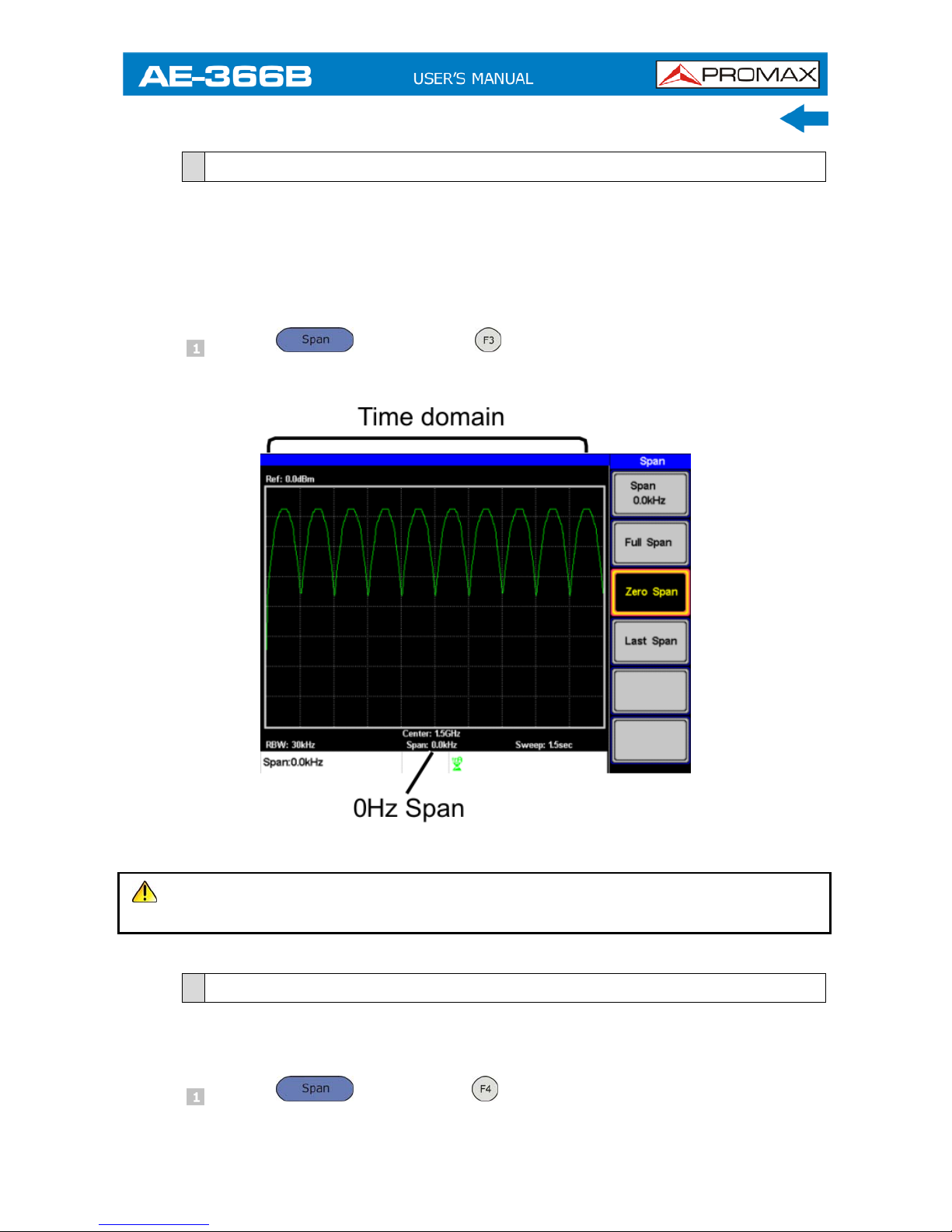
3.2.3
Zero Span
The Zero Span function will set the frequency range of the sweep to 0 Hz and
fixes the start and stop frequencies to the center frequency.
The Zero Span function measures the time domain characteristics of the input
signal at the center frequency. The horizontal axis is displayed in the time
domain.
Press
X Zero Span .
The span changes accordingly.
Figure 20. Amplitude modulation.
NOTE: The measurement functions such as ACPR and OCBW are not available
with the zero span setting.
3.2.4
Last Span
The last span function returns the spectrum analyzer to the previous span
settings.
Press
X Last Span .
Page 28

3.3 Amplitude Settings
The vertical display scale is defined by the reference level amplitude,
attenuation, scale and external gain/loss.
3.3.1
Reference Level
The reference level defines the absolute level of the amplitude on the top
graticule in voltage or power.
Press
X Ref. Level and enter the reference level
amplitude.
Range: -20dBm ~ 20dBm.
Resolution: 10 dBm.
Figure 21.
3-20
July 2018
Page 29
July 2018 3-21
3.3.2
Amplitude Units
The amplitude units can be set from dBm, dBmV or dBuV.
Press
X Units… to change the amplitude units.
Units: dBm, dBmV, dBuV.
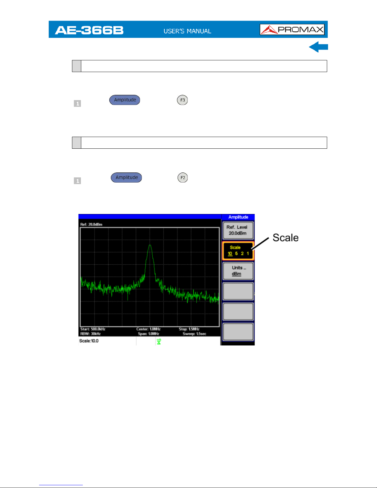
3.3.3
Scale/Div
Sets the logarithmic units for the vertical divisions.
Press
X Scale repeatedly to select the vertical division
units.
Scale Range: 10, 5, 2, 1.
Figure 22.
Page 30
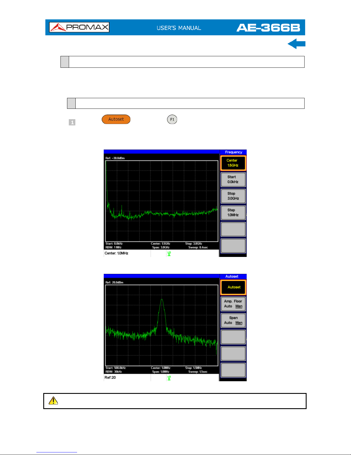
3.4 Autoset
The Autoset function searches the peak signals and picks the signal peak with
the maximum amplitude, and then shows it in the display.
3.4.1
Using Autoset
Press
X Autoset .
Amplitude: Over the full amplitude range.
Span: Over the full span range.
Figure 23. Before Autoset, default state.
Figure 24. After Autoset.
NOTE: RBW setting is reset to Auto when the Autoset function is used.
3-22
July 2018
Page 31
July 2018 3-23
3.4.2
Limiting the Autoset Vertical Search Range
You can set the amplitude floor so that the signals lower than the setting will be
ignored by the Autoset search.
Press
X Amp.Floor and switch the range from Auto to
Man.
Enter the amplitude limit with the number pad and Enter key.
Range: −50 to + 20 dBm.
3.4.3
Limiting the Autoset Horizontal Search Range
You can change the frequency span limit in the display to get a better view of the
Autoset result. By default, the frequency span after Autoset is set at 3 MHz.
Press
X Span and switch the range from Auto to Man.
Enter the span frequency for the Autoset search.
Manual Range: Full amplitude range.
Page 32

3.5 Marker
A Marker shows the frequency and amplitude of a waveform point. The AE-366B
can activate up to 5 markers or marker pairs simultaneously.
The marker table and peak table functions help editing and viewing multiple
markers in a single display.
The delta marker function allows you to see the frequency and amplitude
differences between reference markers.
The AE-366B can automatically move a marker to various locations including the
peak signal, center frequency, and start/stop frequency. Other marker operations
regarding signal peaks are available in the Peak Search function.
Activating a Marker
Activate a Delta Marker
Move Marker Manually
Move Marker to Preset Locations
Move Marker to Trace
Turn All Markers On or Off
Show Markers in Table
Peak Search
Move Marker to Peak
Move Marker and Peak to Center
Search for Peaks
Peak Table
3-24
July 2018
Page 33

July 2018 3-25
3.5.1
Activating a Marker
There are two basic marker types, normal markers and delta markers. Normal
markers are used to measure the frequency/time or amplitude of a point on the
trace. Delta markers are used to measure the difference between a reference
point and a selected point on the trace.
3.5.1.1
Activate a Normal Marker
Press
X Marker and select a marker number.
Marker: 1 ~ 5.
Press to turn the selected marker on.
Press Mode and set the marker mode to Normal.
The display will show the marker on the trace (centered by default) with
the marker measurement at the top of the display.
Figure 25.
Page 34

3.5.1.2
Activate a Delta Marker
Delta markers are marker pairs that measure the difference in frequency and
amplitude between a reference marker and a delta marker.
When delta markers are activated, the reference and delta marker appear at the
position of the selected marker, or in the center of the display if the selected
marker has not yet be activated.
The marker measurement is located at the top of the display, under the “normal
marker” measurement.
Ref: Reference marker, designated as
.
Delta: Delta marker, designated as
.
Press
X Marker and select a marker number.
Press to turn the selected marker on.
Press Mode to set the mode to Delta to activate the delta marker.
Figure 26.
3-26
July 2018
Page 35

July 2018 3-27
3.5.1.3
Move Marker Manually
Press
X Marker and select a marker number.
Use the left/right arrow keys to move the marker one screen division at a
time or the use the scroll wheel to move the marker in fine increments
(one pixel at a time).
Figure 27.
Alternatively, the numeric keypad can be used to directly enter the
frequency of the marker position.
Figure 28.
3.5.1.4
Move Marker to Preset Locations
The currently selected marker (normal marker or delta marker) can be moved to
a number of preset positions:
Center: Move to center frequency.
Peak: Move to the highest peak.
Start: Move to start frequency.
Stop: Move to stop frequency.
Step: Move to step frequency.
Ref. Level: Move to reference level amplitude.
NOTE: When a marker is moved to a preset position the span and other
settings may be automatically changed.
Page 36

► Move marker to peak:
Press
X
To Peak .
► Move marker to center:
Press
X
To Center .
► Move marker to other positions:
Press
X
More X Marker to… and select one of the
preset positions:
Marker to Start .
Marker to Stop .
Marker to Step .
Marker to Ref. Level .
3.5.2
Move marker to Trace
The Marker Trace function moves the selected marker to the currently active
trace.
Press
X Marker and select a marker number.
Press More X Marker Trace and select a trace to assign the
selected marker to. If Auto is selected, the selected marker is
automatically assigned a trace.
Marker Trace: Auto, A, B, C.
3-28
July 2018
Page 37

July 2018 3-29
In the example below, marker 1 is set to trace B.
Figure 29.
3.5.2.1
Turn All Markers On or Off
All markers that have been activated, both normal and delta markers, can be
turned off at the same time with the All Mrk Off function.
Press
X More X All Mrk Off and turn all the markers
off.
3.5.3
Show Markers in Table
The AE-366B has a Marker Table function to show all the active markers and
measurements at once.
Press
X More X Marker Table and turn the marker
table on.
Page 38

The display will split into two screens. The bottom half will show the
Marker Table with the marker No. (normal, reference or delta), frequency
and the amplitude of the marker.
Figure 30.
3.5.3.1
Edit Markers in Marker Table
While the Marker Table function is the active function, the position of each
marker and delta marker can be edited within the marker table.
Use the arrow keys to move the cursor to the frequency column of the
desired marker.
Figure 31.
3-30
July 2018
Page 39
July 2018 3-31
Enter the new position of the marker using the keypad and units keys.
3.5.4
Peak Search
The Peak Search key is used to find trace peaks. The currently active marker is
used in conjunction with the peak functions to mark the peaks that are found.
Peaks can be sorted by frequency or amplitude in the peak table.
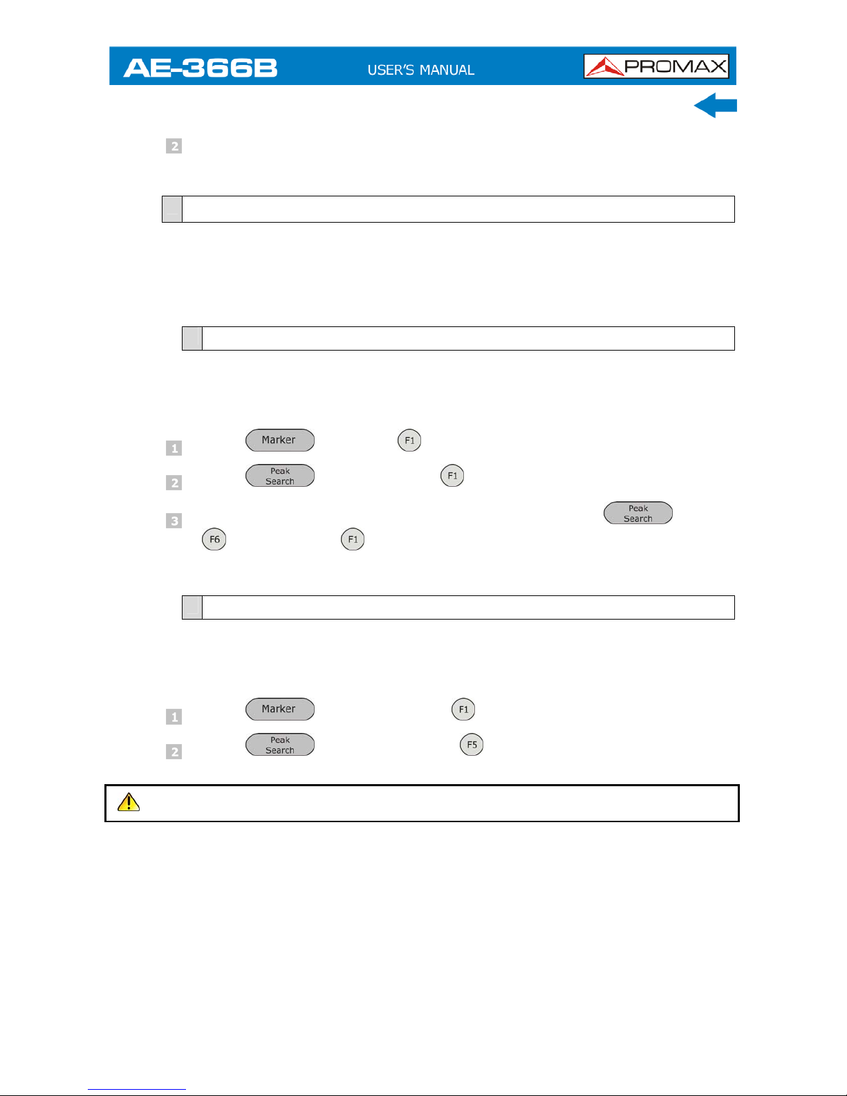
3.5.4.1
Move Marker to Peak
Move the active marker to the highest peak. The highest peak can be either
found once or continuously.
Press
X Marker and select a marker number.
Press X Peak Search .
To continually search for the peak each sweep, press, X More
X Peak Track and set Peak Track to ON.
3.5.4.2
Move Marker and Peak to Center
The Peak to Center function moves the marker to the highest signal peak and
moves the center frequency to that peak.
Press
X Select Marker and select a marker number.
Press X Peak to Center .
NOTE: The span will not be changed.
Page 40

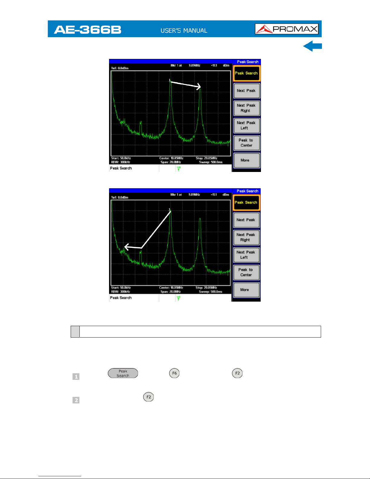
3.5.4.3
Search for Peaks
The
key can be used to search for a number of different peaks.
Next Peak: Searches for next highest peak visible on the display.
Next Peak
Right: Searches for the next peak to the right of the marker.
Next Peak
Left: Searches for the next peak to the left of the marker.
Min Search: Searches for the lowest peak.
Press
X Marker and select a marker number.
Press and select the type of peak you wish to find.
Figure 32. Next Peak.
3-32
July 2018
Page 41
July 2018 3-33
Figure 33. Next Peak Right.
Figure 34. Next Peak Left.
3.5.5
Peak Table
The Peak Table function will display up to 5 peaks. The amplitude and frequency
for each peak is listed.
Press
X
More
X
Peak Table
and turn the peak table
on.
Press Peak Sort and set the sorting type:
Freq: Sort by frequency in ascending order.
Amp: Sort by amplitude in ascending order.
Page 42
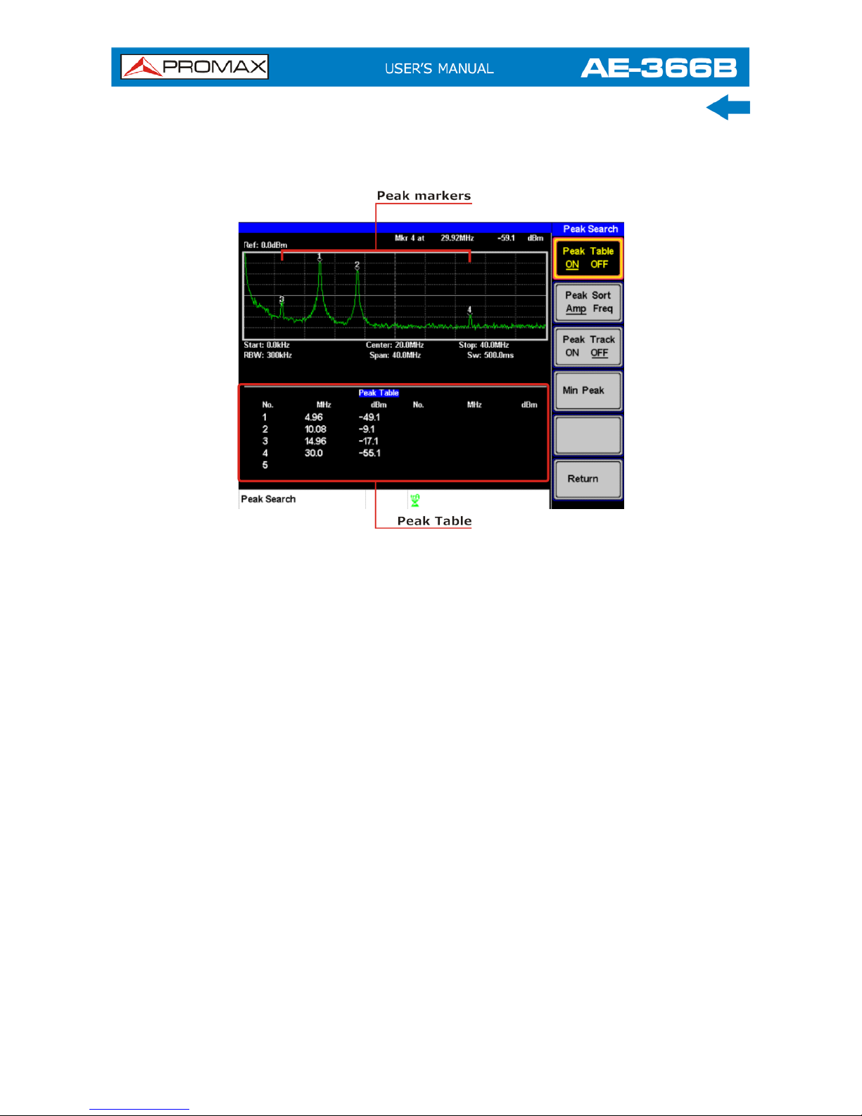
The bottom-half of the screen shows the peak table with the peak marker no.,
frequency and amplitude.
Figure 35.
3-34
July 2018
Page 43

July 2018 3-35
3.6 Measurement
This section describes how to use the automatic measurement modes. The
AE-366B includes the following measurements:
ACPR.
OCBW.
3.6.1
Channel Analysis Overview
Channel analysis measurement includes ACPR (adjacent channel power) and
OCBW (occupied bandwidth) measurements.
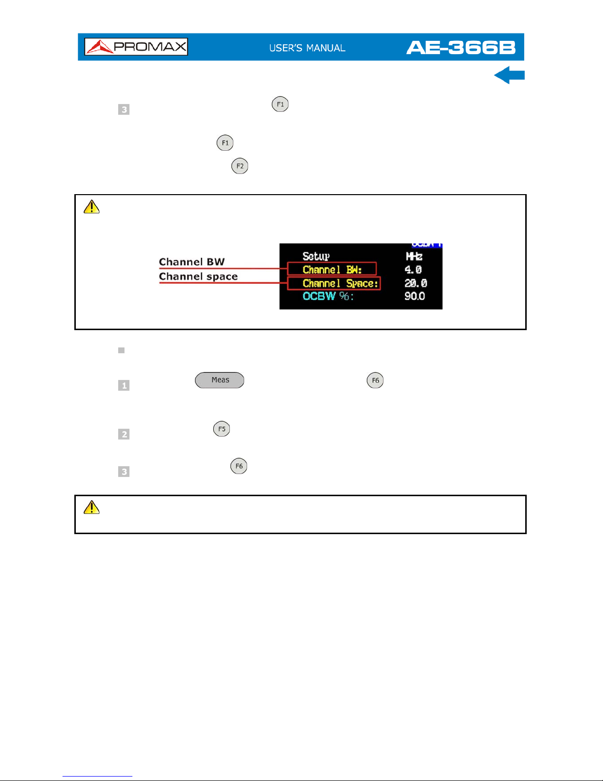
► Parameters:
Channel bandwidth:
The frequency bandwidth the target channel occupies.
Range: Between 0 Hz ~ 3 GHz (0 Hz excepted).
Channel Space:
The frequency distance between each main channel.
Range: Between 0 Hz ~ 3 GHz.
Adjacent channel bandwidth 1 & 2:
The frequency bandwidth the adjacent channels occupy.
Range: Between 0 Hz ~ 3 GHz (0 Hz excepted).
Adjacent channel offset 1 ~ 2
The frequency distance between the adjacent channels and main channel.
Range: 1 Between 0 Hz ~ 3 GHz (0 Hz excepted).
OCBW%
The ratio of occupied bandwidth to the amount of power consumed.
Range: 0 % to 100 %, 0,1 % resolution.
Page 44

3.6.1.1
ACPR
Adjacent channel power refers to the amount of power leaked to the adjacent
channel from the main channel. This measurement is a ratio of the main channel
power to power in the adjacent channel.
Figure 36.
► Operation: Setting up the main channel.
Press
► ACPR and turn ACPR on.
Any other measurement mode will automatically be disabled.
The display splits into two screens. The top screen shows the sweep
waveform. The bottom screen shows the ACPR settings and
measurement results in real time.
3-36
July 2018
Page 45

July 2018 3-37
Turn ACPR off to return back to the normal mode.
Figure 37.
Press Channel Setup… and set the following:
Main CH BW
: Set the bandwidth of the main channel.
Main CH Space
: Specify the channel spacing.
NOTE: The main channel bandwidth and space settings are shown in the setup
area at the bottom of the screen, not on the soft-key icon.
Figure 38.
Page 46

► Operation: Setting up the adjacent channel(s).
Press ADJCH Setup…
to setup the adjacent channels:
Adj CH BW 1
: Sets the bandwidth of the 1st adjacent channel.
Adj CH Offs 1
: Sets the channel offset of the 1st adjacent channel.
Adj CH BW 2
: Sets the bandwidth of the 2nd adjacent channel.
Adj CH Offs 2
: Sets the channel offset of the 2nd adjacent
channel.
NOTE: The adjacent channel bandwidth and space settings are shown in the
setup area at the bottom of the screen, not on the soft-key icons.
Figure 39.
Move Channels Up/Down
Press the
again or press Return repeatedly to return to the
start of the Measure menu tree.
Press CH Up to go to the next main channel.
Press CH Down to go to the previous main channel.
NOTE: The channel space (Main CH Space) setting determines where the next
main channel is located.
3-38
July 2018
Page 47

July 2018 3-39
3.6.1.2
OCBW
Occupied bandwidth measurements are used to measure the power of the
occupied channel as a percentage to the power of the channel.
Figure 40.
► Operation: Setting up the main channel.
Press
X OCBW % and turn OCBW on.
Any other measurement mode will automatically be disabled.
The display splits into two screens. The top shows the channel
bandwidth. The bottom screen shows the OCBW measurement results in
real time.
Turn OCBW off to return back to the normal mode.
Figure 41.
Page 48
Press Channel Setup… and set the following:
Main CH BW : Set the bandwidth of the main channel.
Main CH Space
: Specify the channel spacing.
NOTE: The main channel bandwidth and space settings are shown in the setup
area at the bottom of the screen, not on the soft-key icon.
Figure 42.
Move Channels Up/Down
Press the
again or press Return repeatedly to return to the
start of the Measure menu tree.
Press CH Up to go to the next main channel.
Press CH Down to go to the previous main channel.
NOTE: The channel space (Main CH Space) setting determines where the next
main channel is located.
3-40
July 2018
Page 49

July 2018 3-41
3.7 Limit Line Testing
The Limit Line function is used to set the upper or lower amplitude limits over the
entire frequency range. The limit lines can be used to detect whether the input
signal is above, below or within the limit lines.
The limit lines can be manually edited using 10 frequency points from the start to
the stop frequencies.
3.7.1
Activate a Limit Line
Press
to enter the Limit Line menu.
Press H Limit or L Limit and turn the high or low limit on or off.
H Limit/L Limit: On, Off
The H Limit is shown as a blue line.
The L Limit is shown as a pink line.
Figure 43.
Page 50
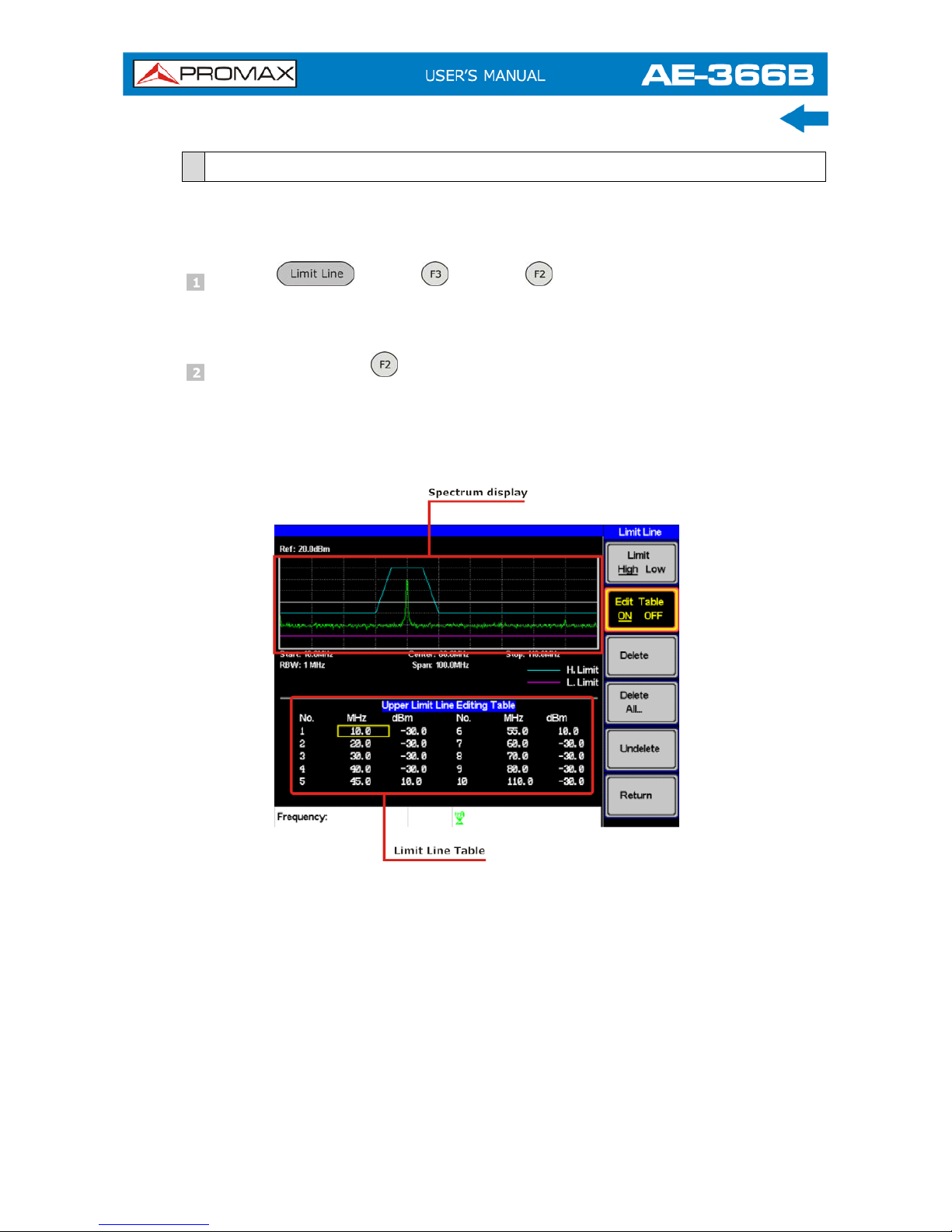
3.7.2
Creating a Limit (Point by Point)
Create a limit manually, point by point. Ten manually selected frequency points
can be used to create the upper or lower limit line.
Press
X
Edit
X
Limit
and select the limit line you wish
to edit.
Limit: High, Low.
Press Edit Table and turn the edit table on.
The AE-366B is split into two screens. The top screen shows the trace
and the selected limit line (high or low) and the bottom screen shows the
limit line table.
Figure 44.
All 10 points will be displayed in a limit line table at the bottom of the
display. By default, each point is set to 0 dBm.
3-42
July 2018
Page 51

July 2018 3-43
Use the arrow keys to move the cursor to the frequency column of the
desired point.
Figure 45.
Enter the new frequency and amplitude of the point using the keypad and
the unit keys.
Repeat steps 3-5 for the remaining points (A maximum of ten points).
To delete the selected point, press Delete .
To delete all the points, press Delete All… .
The points will revert to their default frequency and amplitude
values.
To delete a point from the editing table, press Delete.
The whole points, including the frequency value and the
amplitude are removed. This command reduces the number of
points used in the limit line.
Press Undelete the restore the last point that was deleted.
3.7.2.1
Pass/Fail Testing
The Pass/Fail testing uses the limit lines as boundaries. When the input signal
escapes the boundary of the limit lines, then the test is judged as a FAIL, if the
signal stays within the boundary, the test is judged as a PASS.
Figure 46.
Page 52

NOTE: Before pass/fail testing can begin, limit lines for the upper and/or lower
limits must first be saved and activated.
Press
X
Pass/Fail to turn the testing on or off.
The test result is updated in real-time at the bottom of the display.
Pass:
Fail:
NOTE: At least one limit line (high or low) must be turned on to enable
testing.
If only high limit line is on, each trace point has to be lower than the
high limit line to get a PASS judgment, otherwise get the judgment will
be FAIL.
Conversely, if only low limit line is on then each trace point has to be
higher than the low limit line to get a PASS, otherwise get the test will
be judged a FAIL.
3-44
July 2018
Page 53

July 2018 3-45
3.8 Bandwidth
BW key sets the resolution bandwidth (RBW). The resolution bandwidth and the
sweep time are related. Please take into account how the sweep time is effected
by the resolution bandwidth.
3.8.1
Resolution Bandwidth Setting (RBW)
The RBW (Resolution Bandwidth) defines the width of the IF (intermediate
frequency) filter that is used to separate signal peaks from one another. The
narrower the RBW, the greater the capability to separate signals at close
frequencies. But it also makes the sweep time longer under specific frequency
spans (the display is updated less frequently).
Press
X
RBW and set the RBW to Auto or Man.
Set the resolution bandwidth and unit for Man mode.
Mode: Auto, Man.
Frequency Range: 1 MHz, 300 kHz, 100 kHz.
NOTE: The manual RBW is only available when the span ≤10 MHz. If the span
is greater than 10 MHz then the RBW is automatically set to Auto.
Page 54

3.9 Trace
The AE-366B is able to set the parameters of up to 3 different traces on the
display at once. Each trace is represented by a different color and is updated with
each sweep.
3.9.1
Selecting a Trace
Each trace (A, B, C) is represented by a different color. Trace A is green, trace B
is orange and trace C is yellow. When activated, an icon for each trace color and
function is shown at the bottom of the display. When a trace is selected,
parameters can be set/edited from the Trace menu.
Figure 47.
► Trace Type & Icon
The type of trace used determines how the trace data is stored or manipulated
before being displayed. The analyzer updates each trace according to the type
of trace used.
Clear & Write:
The AE-366B continuously updates the display with each sweep. This is
the default trace type.
Peak Hold, Min Hold:
The maximum or minimum points are maintained for the selected trace.
The trace points are updated each sweep if new maximum or minimum
points are found.
View:
View will hold the selected trace and stop updating the trace data for the
selected trace. Pressing View
will display the trace data that was
cleared using the Blank
key.
3-46
July 2018
Page 55
July 2018 3-47
Blank:
Clears the selected trace from the display and stores trace data. The trace
data can be restored by pressing View
.
► Operation
Press
X
Trace and choose a trace.
Trace: A, B, C.
Select the trace type:
Clear & Write
Peak Hold
View
Blank
More
> Min Hold
NOTE: Traces B and C are set to Blank by default.
Page 56

3.9.2
Trace Math
Performs trace math from two traces (A, B) and stores the results in trace A or
swaps the data from trace A to trace B.
Math functions:
A <--> B: Swaps the data from trace A to B and vice versa.
A + B -> A: Adds trace A and B and stores the result in trace A.
A – B -> A: Subtracts trace B from trace and stores the result in
trace A.
A + const ->A: Adds an offset to trace A.
A – const ->A: Subtracts an offset from trace A.
Press > Trace Math…
and select a trace math function.
A <--> B
A + B -> A
A – B -> A
A + const ->A
A – const ->A
If A + const ->A or A + const ->A was selected, set the constant
(offset value).
Constant: -40 dBm ~ 40 dBm.
3.9.3
Average Trace
The Average function averages the currently selected trace for a user-defined
number of times before it is displayed. This feature smoothes the noise level, but
has the drawback of slowing down the display update rate.
Press
X
More and toggle Avg on.
Set the number of averages.
Range: 4 ~ 100.
Default: 4
3-48
July 2018
Page 57

July 2018 3-49
Figure 48. Average:Off.
Figure 49. Average:On (8x).
Page 58
3.10 Display
The Display key configures the basic display settings as well as the split screen
modes.
3.10.1
Adjusting the LCD Brightness
The LCD brightness levels can be adjusted to five pre-set levels.
Press
X
LCD Dimmer and use either the number pad, the
scroll wheel or arrow keys to set the brightness.
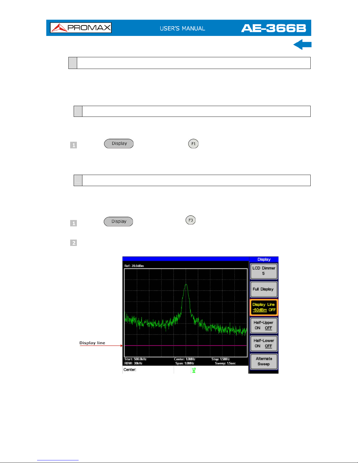
3.10.2
Setting a Display Line (Reference Level Line)
The Display Line function is used to super-impose a reference level line over the
traces.
Press
X Display Line to turn the display line on.
Set the display line level and press Enter.
Figure 50. Display line set at –50dBm.
3-50
July 2018
Page 59
July 2018 3-51
3.10.3
Using the Video Out Port
The AE-366B has a dedicated VGA terminal to output the display to an external
monitor. The video output is always on.
Output resolution: 480 x 640 (fixed).
Connect an external monitor to the rear panel VGA terminal
.
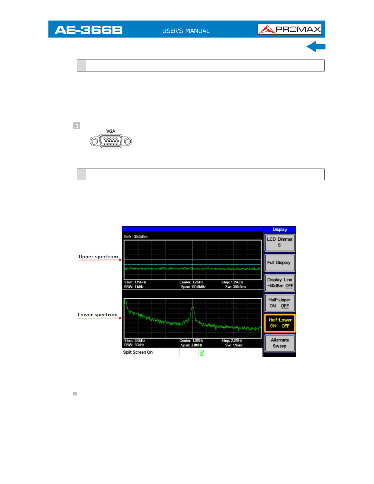
3.10.4
Split Spectrum View
The split spectrum view is able to view two different sweep ranges on the display
at the same time using a split screen view. The top and bottom view can have
independent sweep ranges, amplitudes, spans and other settings. However only
one split screen (top or bottom) can be swept each time.
Figure 51.
► Split Spectrum Functions
Half-Upper:
Half-Upper will put the spectrum analyzer into split screen mode. It will
make the top sweep the active sweep and pause the bottom sweep. When
Half-Upper is on, only the upper sweep parameters can be edited.
Page 60

Half-Lower:
Half-Lower will put the spectrum analyzer into split screen mode. It will
make the bottom sweep the active sweep and pause the top sweep. When
Half-Lower is on, only the lower sweep settings can be edited.
Alternate Sweep:
This setting will alternate the sweep between the bottom and top
spectrums. If alternate sweep is turned on, only the upper sweep
parameters can be edited.
► Operation
Press
> Half-Upper or Half-Lower or Alternate
Sweep
to enable the split spectrum view.
Turning Half – Upper on will automatically turn Half-Lower off.
Turning Half – Lower on will automatically turn Half-Upper off.
If Alternate Sweep is turned on, each sweep will alternate, but
only the upper sweep parameters can be edited.
To return to a full - screen, single spectrum display, press Full Display
.
NOTE: After exiting the split spectrum view, the analyzer will use the settings
from the active window. The settings for the inactive screen will be
retained for the next time that split spectrum view is used.
If the spectrum analyzer was in the Alternate mode, then the upper
sweep settings will be returned.
3-52
July 2018
Page 61

July 2018 3-53
3.11 Save/Recall Files
The AE-366B can save and recall setup data, trace data and limit line data to
and from internal memory. There are five memory locations for each save file
type. These files cannot be saved to USB.
The Hardcopy key can be used to save image files to a USB flash drive.
3.11.1
Save/Recall Setup
Setup data contains all the data necessary to recall the state of the AE-366B to
known state.
Setup data contains the following data:
Center frequency, Start frequency, Stop frequency, Step frequency, Ref. Level,
Scale, Units, RBW.
Save:
To save the current settings, press
X Setup To and
choose a memory location to save to with the arrow keys.
Setup To: 1 ~ 5.
Press to execute the save.
Recall:
To recall a setup, press
X Setup From and choose a
memory location to recall from with the arrow keys.
Setup From: 1 ~ 5.
Press to execute the recall.
Page 62
3.11.2
Save/Recall Trace Data
The trace data can be saved/recalled for any of the A, B or C traces to/from one
of 5 pre-set internal memory locations. The trace data cannot be recalled or
saved to USB.
When saving or recalling trace data from a split spectrum, only the active
spectrum is saved/recalled.
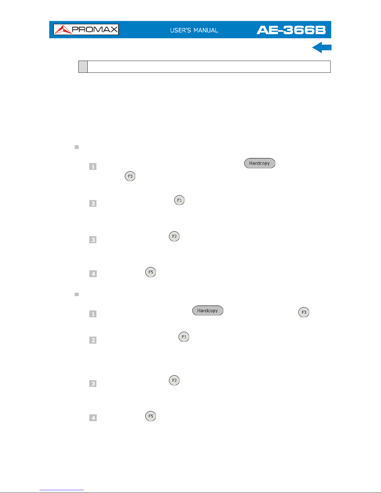
Save:
To save the current trace data, press
X
Save Trace
Data.
Press Source Trace and select the source:
Source: A, B, C.
Press Destination and select the memory location to save to:
Destination: 1 ~ 5.
Press Start to save the selected trace data.
Recall:
To recall trace data, press
X
Recall Trace Data .
Press Source Trace and select the memory location to recall
from:
Source: 1 ~ 5.
Press Destination and select the destination trace:
Destination: A, B, C.
Press Start to save the selected trace data.
3-54
July 2018
Page 63
July 2018 3-55
3.11.3
Save/Recall Limit Lines
Upper and lower limit lines can be saved to one of 5 pre-set internal memory
locations. The limit line data cannot be saved to USB.
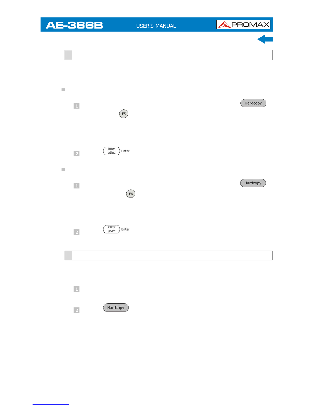
Save:
To save the current upper and lower limit lines, press >
Limitln to
and choose a memory location to save to with the
arrow keys.
Limit line: 1 ~ 5.
Press to execute the save.
Recall:
To recall pre-saved upper and lower limit lines, press X
Limitln from
and choose a memory location to recall from with
the arrow keys.
Limit line: 1 ~ 5.
Press to execute the recall.
3.11.4
Saving an Image File (Hardcopy)
The Hardcopy key can be used to save a screenshot of the display to a USB flash
drive. The screen shot is saved as a bitmap file.
Insert a USB flash drive into the USB port.
Press and the image file will begin saving.
Wait a few moments for the file to save. When the file has
finished saving, “Screen Saved OK” will appear at the
bottom of the display.
Page 64
NOTE: The file name will be automatically created in the following format:File
name: SCRXX.bmpWhere XX is a number that is incremented each
time the file is saved.
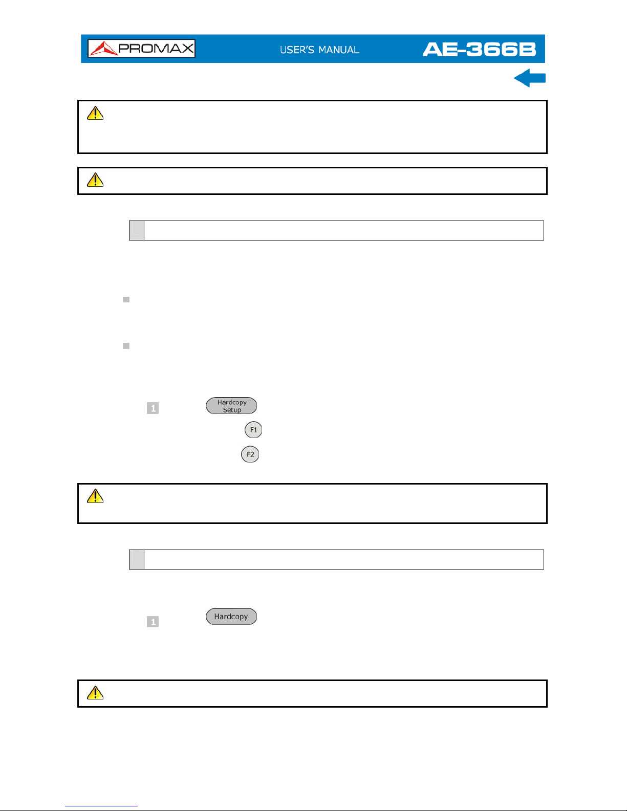
WARNING: Do not remove the USB drive until the file has completed saving.
3.11.5
Hardcopy Setup
The Hardcopy Setup key is used set the image file properties of the bitmap file
that is created when the Hardcopy key is pressed.
Ink Normal:
This is the normal, default image setting.
Ink Saving:
This will invert all the colors on the display so that the file will conserve ink
when printed.
Press and choose the image type:
Ink Normal
Ink Saving
NOTE: The next time the Hardcopy key is pressed, the image will be saved
using the settings above.
3.11.6
Load Default Settings
The Preset key is used to load the default settings.
Press .
The system will load the preset settings and the screen will
update with the new settings.
NOTE: The default settings cannot be changed.
3-56
July 2018
Page 65

July 2018 3-57
3.12 System Settings
3.12.1
System Information
► Description
The System Information displays the following:
Serial Number:
XX digit serial number.
HW Version:
Hardware version.
FW Version:
Firmware version.
SW Version:
Software version.
Language:
Shows the language number as seen in the System>Language menu.
► Operation
Press
►
Information to display the system
information.
The system information will be displayed on the system
menu soft-keys.
Figure 52.
Page 66

3.12.2
System Language
The language option sets the icon display language.
Press
X
Language… to bring up the Language menu.
Choose a system language. The language number is the number that
will be displayed in the system information.
3-58
July 2018
Page 67

July 2018 4-59
4 REMOTE CONTROL
This chapter describes basic configuration of IEEE488.2 based remote control.
4.1 Interface Configuration
4.1.1
Configure Remote Interface
USB configuration:
PC side connector: Type A, host.
Equipment side
connector: Rear panel Type B, slave.
Speed: 1.1/2.0 (full speed).
RS 232 configuration:
PC side connector: RS232 male port.
Equipment side
connector: RS232 female port.
Baud Rate: 9600, 19200, 38400, 57600, 115200.
Parity: None, Even, Odd, Space, Mark, Multidrop.
Stop bit: 1, 1.5, 2.
Data bit: 5, 6, 7, 8.
The AE-366B can use either the type B USB port or the RS232 on the rear panel
for remote control.
When using the USB B port, the AE-366B uses a USB driver to simulate an
RS232 connection with a PC via USB. It is these RS232 settings that are
configured for remote control.
Before using the USB B port for remote control, please install the USB driver.
Page 68

► Panel Operation
USB Connection:
Connect a USB cable from the PC to the rear panel USB B port.
RS232 Connection:
Connect an RS232C cable from the PC to the rear panel RS232
port.
Press X Serial Port… X Serial to enter the remote
configuration.
Set the following RS-232 settings using the arrow keys:
Baud Rate
: 9600, 19200, 38400, 57600, 115200.
Parity
: None, Even, Odd, Space, Mark, Multidrop.
Stop Bit
: 1, 1.5, 2.
Data
: 5, 6, 7, 8.
4.1.2
Remote Control Function Check
Invoke a terminal application such as MTTTY (Multi-Threaded TTY).
To check the COM port No., see the Device Manager in the PC.
For WinXP go to;
Control panel Î System Î Hardware tab.
Run this query command via the terminal after the instrument has been
configured for remote control.
*idn?
This should return the Manufacturer, Model number, Serial number, and
Firmware version.
NOTE: For further details or if you have trouble running this function check,
please see the programming manual.
4-60
July 2018
Page 69

July 2018 4-61
4.2 Command Syntax
Compatible Standard:
IEEE488.2 Partial compatibility.
SCPI, 1999 Partial compatibility.
Command Structure:
SCPI (Standard Commands for Programmable Instruments) commands
follow a tree-like structure, organized into nodes. Each level of the
command tree is a node. Each keyword in a SCPI command represents
each node in the command tree. Each keyword (node) of a SCPI command
is separated by a colon (:).
For example, the diagram below shows an SCPI sub-structure and a
command example.
Figure 53.
Command types:
There are a number of different instrument commands and queries. A
command sends instructions or data to the unit and a query receives data
or status information from the unit.
Single Command A single command with/without a parameter.
Example: meas:freq:cen 100 MHz
Query A query is a simple or compound command
followed by a question mark (?). A parameter
(data) is returned.
Example: meas:freq:cen?
Page 70

Command Format:
Figure 54.
Command header.
Space.
Parameter 1.
Optional space.
Unit or suffix.
Common Input/Return Parameters:
Type Description Example
<Boolean> Boolean logic 0, 1
<NR1> integers 0, 1, 2, 3
<NR2> decimal numbers 0.1, 3.14, 8.5
<NRf> any of NR1, 2
1, 1.5
<freq> <NRf> + unit
Unit = kHz, MHz, GHz.Note: The unit can be
omitted (defaults to currently set unit).
2.5 mhz
<refl> <NRf> + unit
Unit = dBm, dBmV, dBuVNote: The unit can be
omitted (defaults to currently set unit).
-30 dBm
<ampl> NR3 +unit
Note: The unit can be omitted. (Unit defaults
to current unit)
30.0 dBm
<trace data> { -92, -91, ……., -89, -92, -92, -91 }
CSV data that represents each point in a trace.
<string> ASCII string data.
Message Terminator:
LF Line feed code (0x0A).
4-62
July 2018
Page 71

July 2018 4-63
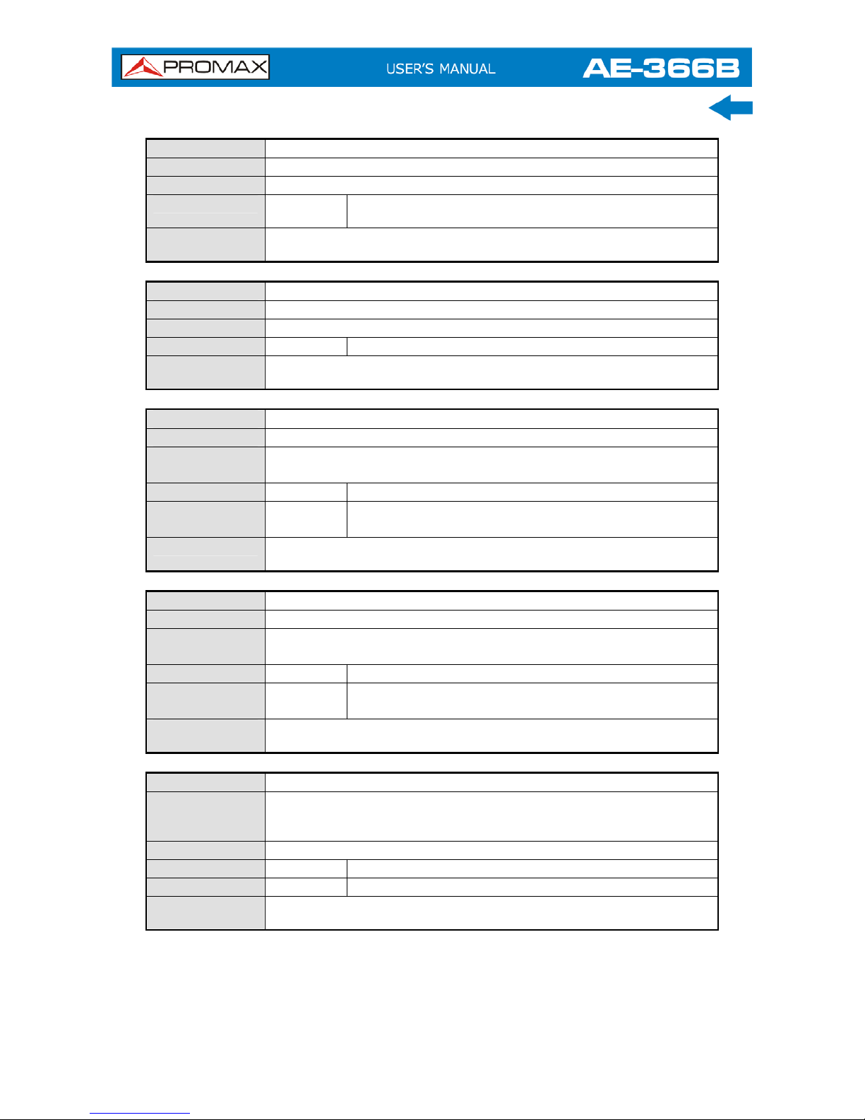
4.3 Command List
4.3.1
IEEE488.2 Standard Commands
Name
*IDN?
Description
Queries the manufacturer, model number, serial number, and
firmware version of the instrument.
Query
Syntax
*IDN?
Return
parameter
<string> Returns the instrument identification
4.3.2
Sweep Commands
Name
si
Description
Stops the sweep.
Example
si
Name
sn
Description
Continues a stopped sweep.
Example
sn
Name
ts
Description
Resets the sweep and starts it once (i.e., sweeps one time).
Example
ts
4.3.3
Frequency Commands
Name
meas:freq:cen
Description
Sets or queries the center frequency.
Syntax
meas:freq:cen<freq>
Query
Syntax
meas:freq:cen?
Parameter
<freq> Center frequency.
Return
parameter
<freq> Returns the frequency and unit.
Example
meas:freq:cen 100kHz
Sets the center frequency to 100kHz.
Query
example
meas:freq:cen?
>100 kHz
Page 72

Name
meas:freq:st
Description
Sets or queries the start frequency.
Syntax
meas:freq:st<freq>
Query
Syntax
meas:freq:st?
Parameter
<freq> Start frequency.
Return
parameter
<freq> Returns the start frequency and unit.
Example
meas:freq:st 100mhz
Sets the start frequency to 100MHz
Query
example
meas:freq:st?
>100000 kHz
Name
meas:freq:stp
Description
Sets or queries the stop frequency
Syntax
meas:freq:stp<freq>
Query
Syntax
meas:freq:stp?
Parameter
<freq> Stop frequency.
Return
parameter
<freq> Returns the stop frequency and unit.
Example
meas:freq:stp 100 mhz
Sets the stop frequency to 100MHz
Query
example
meas:freq:stp?
>100000 kHz
4.3.4
Span Commands
Name
meas:span
Description
Sets or queries the frequency span
Syntax
meas:span <freq>
Query
Syntax
meas:span?
Parameter
<freq> Span frequency range.
Return
parameter
<freq> Returns the span and unit.
Example
meas:span 10 mhz
Sets the span to 10MHz
Query
example
meas:span?
>10000.0 kHz
Name
meas:span:full
Description
Sets the span to the full span.
Syntax
meas:span:full
4-64
July 2018
Page 73

July 2018 4-65
4.3.5
Amplitude Commands
Name
meas:refl:unit
Description
Sets the reference level unit
Syntax
meas:refl:unit {1/2/3}
Query
Syntax
meas:refl:unit?
1 dBm
2 dBmV
Parameter/
Return
parameter
3
dBµV
Query
example
meas:refl:unit?
>1
The reference level unit are dBm.
Name
meas:refl
Description
Sets or queries the reference level.
Syntax
meas:refl <refl>
Query
Syntax
meas:refl?
Parameter
<refl> Reference level in the currently selected unit (from
the meas:refl:unit command).
Return
parameter
<refl>
Returns reference level and unit.
Example
Meas:refl 10
Sets the reference level to 10 dBm (for unit = dBm).
Query
example
meas:refl?
>10 dBm
4.3.6
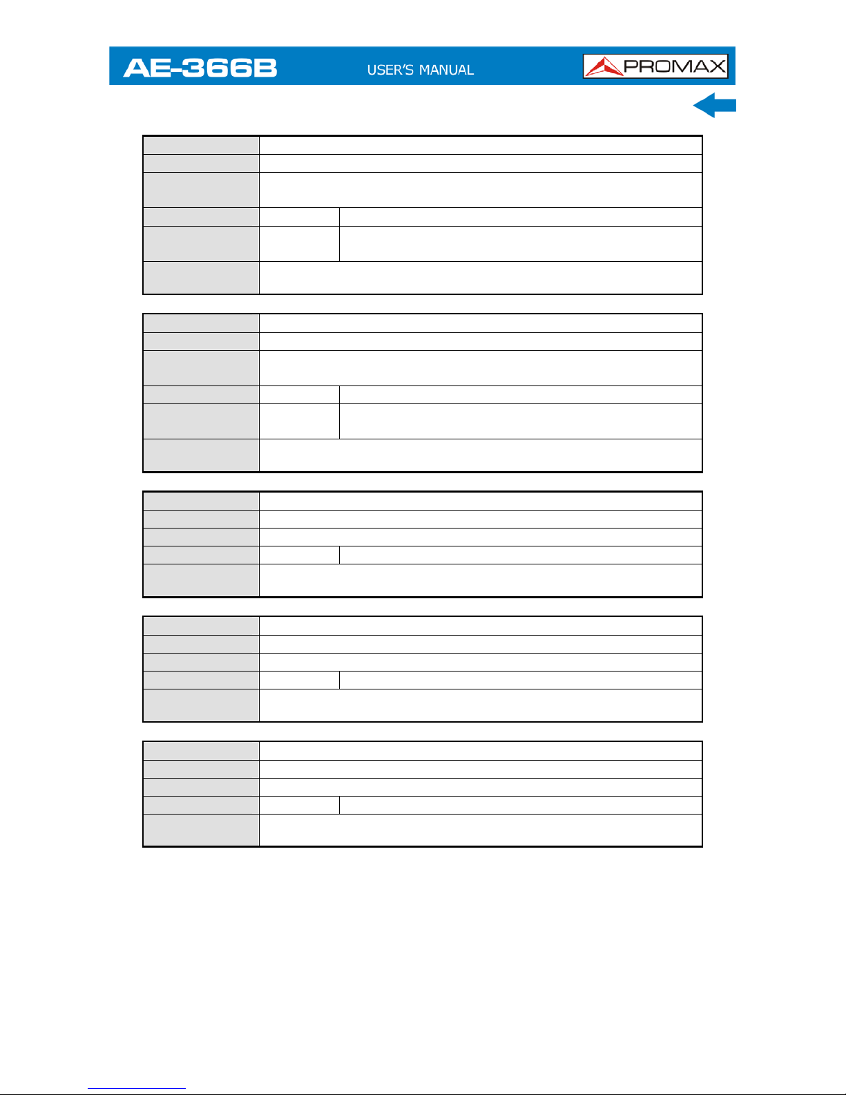
Marker and Peak Search Commands
Name
meas:mark:on
Description
Sets or queries which markers are turned on.
Syntax
meas:mark:on {<NR1>/all}
Query
Syntax
meas:mark:on <NR1>?
Parameter
<NR1>
all
Marker number 1~5.
All markers.
Return
parameter
ON
OFF
The selected marker is on.
The selected marker is off.
Example
meas:mark on 1
Turns marker 1 on.
Query
example
meas:mark 1?
>OFF
Page 74
Name
meas:mark:off
Description
Sets which markers are turned off.
Syntax
meas:mark:off {<NR1>/all}
Parameter
<NR1>
All
Marker number 1~5.
All markers.
Example
meas:mark off 1
Turns marker 1 off.
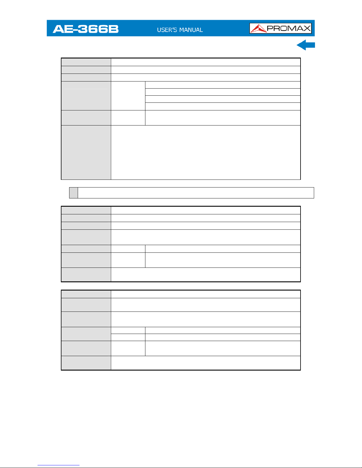
Name
meas:mark:norm
Description
Sets the selected marker to normal mode.
Syntax
meas:mark:norm<NR1>
Parameter
<NR1>
Marker number 1~5.
Example
meas:mark:norm 1
Sets marker 1 to normal mode.
Name
meas:mark:norm:freq?
Description
Queries the frequency of the selected normal marker.
Query
syntax
meas:mark:norm:freq <NR1>?
Parameter
<NR1>
Marker number 1~5.
Return
parameter
<freq>
Returns the frequency and unit of the selected
marker.
Example
meas:mark:norm:freq1?
>1.5GHz.
Name
meas:mark:norm:level?
Description
Queries the amplitude of the selected normal marker.
Query
syntax
meas:mark:norm:level <NR1>?
Parameter
<NR1>
Marker number 1~5.
Return
parameter
<amp>
Returns the amplitude and unit of the selected
marker.
Example
meas:mark:norm:level1?
>10.0dBm.
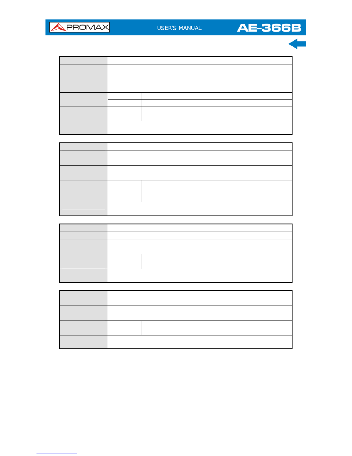
Name
meas:mark:delta
Description
Sets the selected marker to delta mode. It also sets the relative
frequency of the delta marker (in relation to the normal marker
frequency).
Syntax
meas:mark:delta <NR1> <freq>
Parameter
<NR1>
Marker number 1~5.
<freq>
Relative frequency of the delta marker.
Example
meas:mark:freq110 MHz
Turns delta marker 1 on and sets its offset to 10MHz.
4-66
July 2018
Page 75
July 2018 4-67
Name
meas:mark:delta:freq?
Description
Queries the (relative) frequency of the selected delta marker.
Query
syntax
meas:mark:delta:freq <NR1>?
Parameter
<NR1>
Marker number 1~5.
Return
parameter
<freq>
Returns the relative frequency and unit of the
selected delta marker.
Example
meas:mark:norm:freq1?
>12.0kHz.
Name
meas:mark:delta:level?
Description
Queries the amplitude of the selected delta marker.
Query
syntax
meas:mark:delta:level <NR1>?
Parameter
<NR1>
Marker number 1~5.
Return
parameter
<amp>
Returns the amplitude and unit of the selected delta
marker.
Example
meas:mark:delta:level1?
>10.0dBm.
Name
meas:mark:tomin
Description
Sets the selected marker to the minimum peak.
Syntax
meas:mark:tomin <NR1>
Parameter
<NR1>
Marker number 1~5.
Example
meas:mark:tomin1
Sets marke 1 to the minimum peak.
Name
meas:mark:topeak
Description
Sets the selected marker to the peak.
Syntax
meas:mark:topeak <NR1>
Parameter
<NR1>
Marker number 1~5.
Example
meas:mark:topeak1
Sets marker 1 to the peak.
Name
meas:mark:tonp
Description
Moves the selected normal or delta marker to the next peak.
Syntax
meas:mark:tonp <NR1>
Parameter
<NR1>
Marker number 1~5.
Example
meas:mark:tono1
Moves marker 1 to the next peak.
Page 76

Name
meas:mark:trace
Description
Sets the selected marker to the selected trace.
Syntax
meas:mark:topeak <NR1> <trace>
<NR1>
Marker number 1~5.
0 Auto (auto assign a trace)
1 TraceA
2 TraceB
Parameter
<trace>
3 TraceC
Example
meas:mark:trace 1 2
Sets marker 1 to trace B.
4.3.7
Trace Commands
Name
meas:tra:val1:val2
Description
Sets the mode for the selected trace.
Syntax
meas:tra <trace><mode>
1 Trace A
2 Trace B
<trace>
3 Trace C
1 Clear and write mode
2 Peak hold mode
3 View mode
4 Blank Mode
Parameter
<mode>
5 Minimum hold mode
Example
meas:tra 1 1
Sets trace A to clear and write mode.
Name
meas:tra:avg:on
Description
Turns the average function on and sets the number of averages
for the selected trace.
Syntax
meas:tra:avg:on <trace><NR1>
1 Trace A
2 Trace B
<trace>
3 Trace C
Parameter
<NR1> 4~20 Number of averages.
Example
meas:tra:avg:on 1 4
Sets the number of averages used for Trace A to 4.
Name
meas:tra:avg:off
Description
Turns the average function off for the selected trace.
Syntax
meas:tra:avg:on <trace>
1 Trace A
2 Trace B
3 Trace C
Parameter
<trace>
all All traces.
Example
meas:tra:avg:off all
Turns the average function off for all the traces.
4-68
July 2018
Page 77
July 2018 4-69
Name
meas:tra:read
Description
Returns the all the trace data for the selected trace.
Syntax
meas:tra:read? <trace>
1 Trace A
2 Trace B
3 Trace C
Parameter
<trace>
all All traces.
Return
parameter
<trace
data>
Comma separated data values encapsulated in
brackets. I.e., {-92, -91, -90, .........-81}
Example
meas:tra:read?1
>{-92, -91, -90, -90, -90, -88,.........-89, -92, -92, -91}
Returns the trace data for the selected trace(s). A total of 501
trace points are returned, from the start frequency to the stop
frequency. If “all” is selected, the trace data is returned in three
lots, {TraceA}{TraceB}{TraceC}. The units are in decibels. If
the selected trace is not active, os will be returned for each trace
point.
4.3.8
Power Measurement Commands
Name
meas:acpr
Description
Turns the ACPR function on or off, or queries its status.
Syntax
meas:acpr {on/off}
Query
syntax
meas:acpr?
Parameter
on ACPR mode = on
Return
parameter
off ACPR mode = off
Example
meas:acpr on
Turns the ACPR function on.
Name
meas:acpr:lower?
Description
Returns the lower ACPR measurement result for the selected
channel offset (offset 1 or 2).
Query
syntax
meas:acpr:lower? {1/2}
1 Channel offset 1
Parameter
2 Channel offset 2
Return
parameter
<NR2> Returns the ACPR measurement result.
Example
meas:acpr:lower?1
>6.0
Page 78
Name
meas:acpr:upper?
Description
Returns the upper ACPR measurement result for the selected
channel offset (offset 1 or 2).
Query
syntax
meas:acpr:upper? {1/2}
1 Channel offset 1
Parameter
2 Channel offset 2
Return
parameter
<NR2> Returns the ACPR measurement result.
Example
meas:acpr:lower?1
>-11.8
Name
meas:ocbw
Description
Turns the OCBW function on or off, or queries its status.
Syntax
meas:ocbw? {on/off}
Query
syntax
meas:ocbw?
On OCBW mode=on
Parameter/
Return
parameter
Off OCBW mode=off
Example
meas:ocbw on
Turns the OCBW function on.
Name
meas:ocbw:bw?
Description
Returns the OCBW in kHz.
Query
syntax
meas:ocbw:bw?
Return
parameter
<freq> Returns the OCBW in kHz
Example
meas:ocbw:bw?
>4000kHz
Name
meas:ocbw:chpw?
Description
Returns the channel power in the current unit.
Query
syntax
meas:ocbw:chpw?
Return
parameter
<power> Returns the channel power
Example
meas:ocbw:chpw?
>-63.5
4-70
July 2018
Page 79

July 2018 4-71
4.3.9
Limit Line Commands
Name
meas:Imtline:passfail
Description
Turns the Pass/Fail test on/off or queries its state.
Syntax
meas:Imtline:passfail {on/off}
Query
syntax
meas:Imtline:passfail
On Turns the pass/fail test on.
Parameter
Off Turns the pass/fail test off.
0 Fail
Return
parameter
1 Pass
Query
Example
meas:Imtline:passfail?
>0
Name
meas:Imtline:on
Description
Turns the limit lines on.
Syntax
meas:Imtline:on
Name
meas:Imtline:off
Description
Turns the limit lines off.
Syntax
meas:Imtline:off
4.3.10
BW Commands
Name
con:rbw:auto
Description
Sets the RBW to Auto.
Syntax
con:rbw:auto
Name
con:rbw?
Description
Returns the RBW.
Query
syntax
Con:rbw?
0 30kHz
1 100kHz
2 300kHz
Return
parameter
<NR1>
3 1MHz
Example
Con:rbw?
>1
Page 80

Name
con:rbw:man
Description
Sets the RBW for manual mode.
Syntax
Con:rbw:man {0/1/2/3/}
1 100kHz
2 300kHz
Return
parameter
<NR1>
3 1MHz
Example
con:rbw:man1
Sets the RBW to 100kHz.
Name
con:rbw:mode?
Description
Returns the RBW mode.
Query
Syntax
con:rbw:mode?
auto Auto mode
Return
parameter
manual Manual mode
Example
con:rbw:mode?
>auto
Name
con:swt?
Description
Returns the sweep time in milliseconds.
Query
Syntax
con:swt?
Return
parameter
<NRf>
Example
con:swt?
>1500
4.3.11
Display Commands
Name
con:disp:split:upper
Description
Turns on the split window function and sweeps the top window.
Syntax
Con:disp:split:upper
Name
con:disp:split:lower
Description
Turns on the split window function and sweeps the bottom
window.
Syntax
Con:disp:split:lower
Name
con:disp:split:alt
Description
Sweeps the upper and lower windows alternatively in the split
window mode.
Syntax
Con:disp:split:lower
Name
con:disp:split:full
Description
Returns the spectrum analyser to single window mode. The
upper window is used as the active window.
Syntax
Con:disp:split:full
4-72
July 2018
Page 81

July 2018 4-73
4.3.12
Preset Commands
Name
con:preset
Description
Loads the factory default settings. This is the equivalent to
pressing the Preset key.
Syntax
con:preset
4.3.13
System Commands
Name
con:sys:ser?
Description
Returns the serial number.
Query
syntax
con:sys:ser?
Return
parameter
<string> Returns the serial number in the following format:
XXXXXXXX
Example
Con:sys:ser?
>XXXXXXXX
Page 82

5 FAQ
► I connected the signal but it does not appear on screen.
► The trace is updated too slowly.
► I cannot see the trace on the screen.
► The performance does not match the specification.
I connected the signal but it does not appear on screen.
Run Autoset and let the AE-366B find the best display scale for your
target signal. Press the Autoset key, then press Autoset
.
The trace is updated too slowly on the screen.
The sweep time determines how often the trace is updated on the screen.
To increase the sweep time, try reducing the span or using a wider RBW
setting.
I cannot see the trace on the screen.
If you cannot see the trace on the screen, there may be a number of
possibilities.
The trace is just off screen: Try to adjust the reference level with
the amplitude key.
The trace may be in the “Blank” mode: Putting the trace into view
mode will enable the trace to be viewed again.
The performance does not match the specification.
Make sure the device is powered On for at least 30 minutes, within
+20 °C ~ +30 °C. This is necessary to stabilize the unit to match the
specification.
5-74
July 2018
Page 83

July 2018 6-75
6 SPECIFICATIONS
6.1 Specifications AE-366B
FREQUENCY
Frequency Range
Setting Range 150 kHz to 3 GHz.
Center Frequency
Setting Resolution 0.1 MHz.
Accuracy within ± 50kHz
(frequency span: 0.3 GHz to 2.6 GHz, 20 ± 5 °C).
Frequency Span
Setting Range 1 MHz to 3 GHz.
Accuracy within ± 3%
(frequency span: 0.3 GHz to 2.6 GHz, 20 ± 5 °C).
Resolution Bandwidth
Setting Range 30 kHz, 100 kHz, 300 kHz, 1 MHz.
SSB Phase Noise -85 dBc/Hz (typical, 500 kHz offset, RBW: 30 kHz, Sweep time: 1.5s,
Span:1MHz@1GHz)
Inherent Spurious Response less than –45dBc @ -40 dBm Ref. Level (typical less than –50 dBc).
AMPLITUDE
Reference Level
Input Range +20 to –40 dBm.
Unit dBm, dBV, dBμV.
Average Noise Level ≤-100 dBm.
(typical, center frequency:1 GHz RBW:30 kHz)
Frequency Characteristic within ± 3.0dB @300MHz ∼ 2.6 GHz
within ± 6.0dB @ 80 ∼ 300 MHz, 2.6 ∼ 3 GHz.
Accuracy within ± 2 dB (1 GHz); SPAN: 5 MHz; Ref. Level odBm, input signal
–10 dBm.
Input
Input impedance 50 Ω.
Input VSWR less than 2.0@input att ≥ 10 dB.
Input damage level +30 dBm (CW average power), 25 VDC.
Input connector N connector.
Page 84

SWEEP
Sweep Time
Setting Range 300 ms to 8.4 s, auto (not adjustable).
Accuracy within ± 2% (frequency span: full span).
GENERAL
Communication
Display 640 x 480 RGB color LCD.
Interface
RS-232C Sub-D female-D 9 pins
USB Connector USB Host/Device full speed supported.
USB Format Supports FAT/FAT32 only.
VGA Output Sub-D female 15 pins.
Power Source AC 100-240V, 50/60 Hz.
OPERATING ENVIRONMENTAL CONDITIONS
Operating Temperature From 5 to 45 °C (Guaranteed at 25 ±5°C, without soft carrying
case).
Operating Humidity Less than 45 °C / 90 % RH.
Storage Temperature -20 to 60 °C, less than 60 °C / 70 % RH.
MECHANICAL FEATURES
Dimensions 115.1 (W) x 152 (H) x 296 (L) mm.
Weight 2.2 kg
INCLUDED ACCESSORIES
1 x DG0140 Quick Reference Guide.
1 x AD059 "N"/M - BNC/H Adapter.
1 x Power Cord.
RECOMMENDATIONS ABOUT THE PACKING
It is recommended to keep all the packing material in order to return the equipment, if necessary, to the
Technical Service.
6-76
July 2018
Page 85

July 2018 6-77
6.2 Default Settings
► Frequency
Center Frequency: 1.5GHz
Start Frequency: 0Hz
Stop Frequency: 3GHz
CF Step: Auto
► Span
Span: 3GHz
► Amplitude
Reference level: -30.0dBm
Scale Div: 10
Units: dBm
► Autoset
Amp.Floor: Auto
Span: Auto
► Marker
Marker: Off
► Peak Search
N/A
► Meas
ACPR: Off
OCBW: Off
► Limit Line
H Limit: Off
L Limit: Off
Pass/Fail: Off
► BW
RBW: Auto
Page 86

6-78
July 2018
► Trace
Trace: A: Clear&Write
Average: Off
► Display
Full Display: Active
Display line: off
► Memory
N/A
► Preset
N/A
► Hardcopy
N/A
► Hardcopy Setup
Ink Normal
► System
N/A
 Loading...