

Page 1
Trademark of the
DVB - Digital Video
Broadcasting Project
Find the user's manual on the download area at: www.promaxelectronics.com
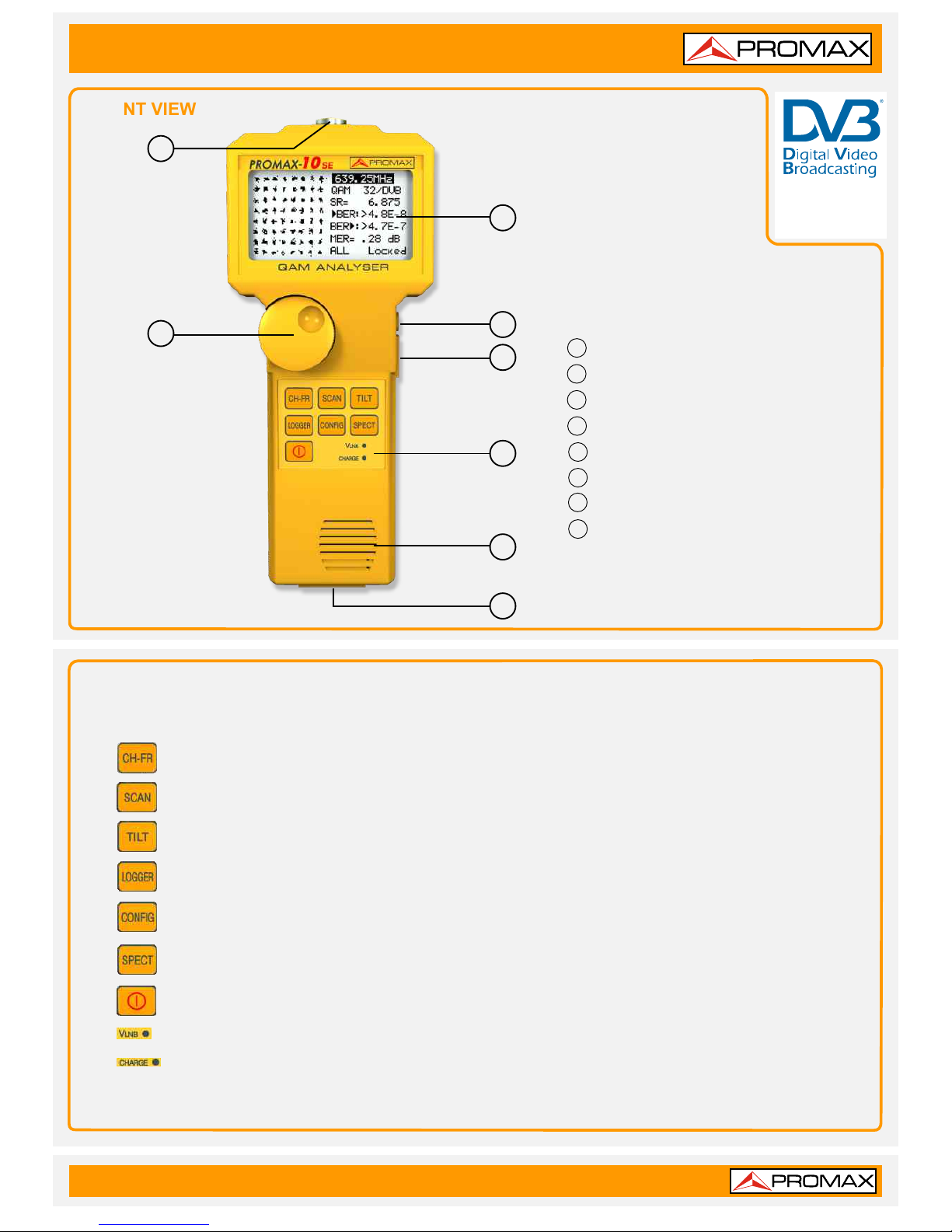
FRONT VIEW
1
2
3
4
“F” male base connector.
Rotary selector/Push button.
Graphic display with back lighting.
DC power adapter external input.
5
6
7
8
Volume control.
Select Function keypad.
Loudspeaker..
Service Connector.
KEYBOARD
Selects the CHANNEL - FREQUENCY operating mode.
Selects the SCAN operating mode.
Selects the TILT operating mode.
Selects the DATALOGGER operating mode. Enables multiple measurements to be taken, visualised,
printed or transferred to a PC automatically.
Access to CONFIGURATION menus specific to each operating mode and to the global
configuration menu of the unit.
Selects the SPECTRUM ANALYSER and the TRANSIENT DETECTOR operating modes.
On/Off key.
LNB external supply indicator.
Battery charge indicator.
1
2
3
4
5
6
7
8
QUICK REFERENCE GUIDE
PROMAX-
8 10 SE/
Page 2
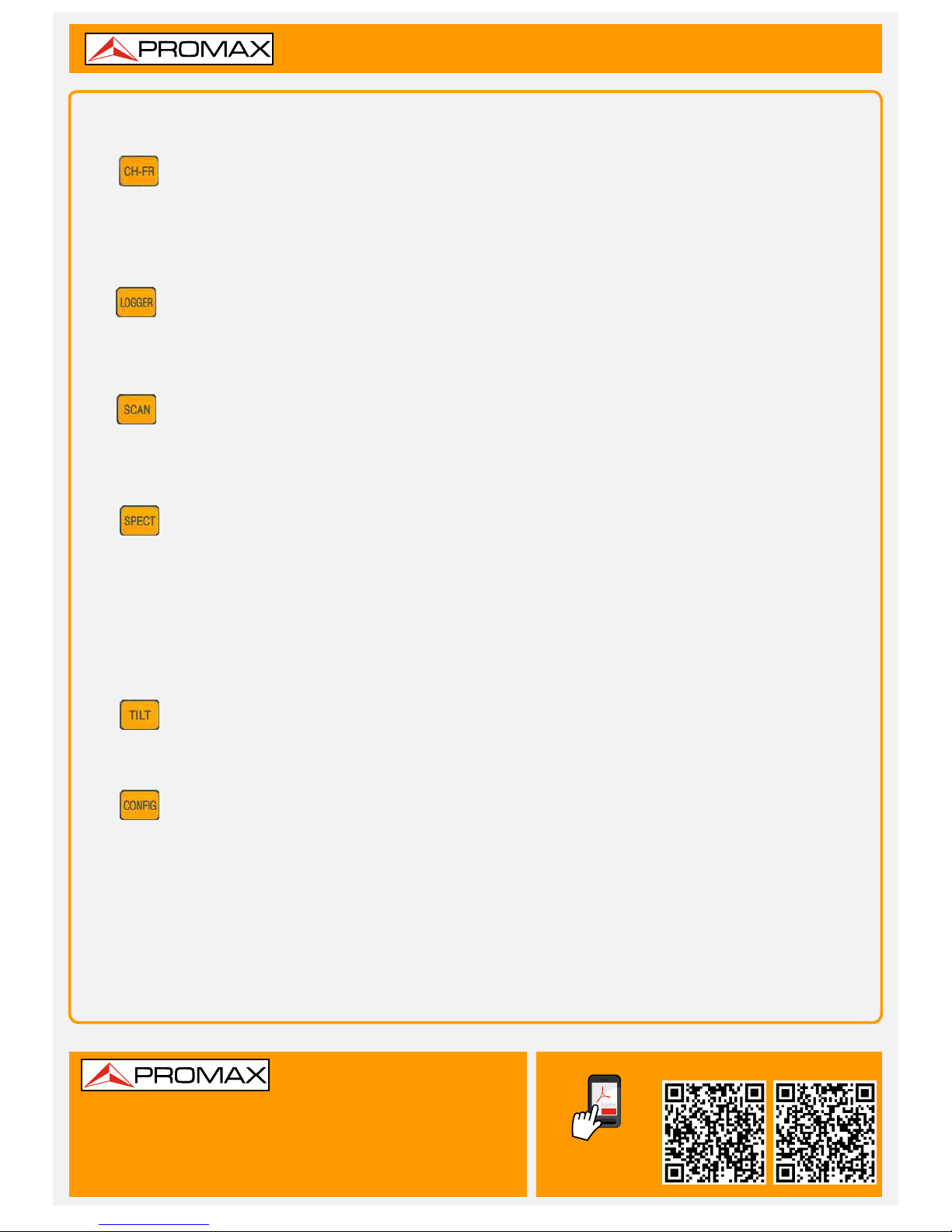
FUNCTION KEYS
02-07-2013 (0 DG0120)
v1.0
It changes between frequency tuning and channel tuning. The operating mode measures the video carrier
level, the Carrier/Noise ratio (C/N), the Video/Audio ratio (V/A) and activates audio carrier demodulation for
analogue channels. For digital channels, it measures the Channel Power and the Carrier/Noise (C/N) ratio. It
also measures the CSO and CTB intermodulation. Only for PROMAX- , it measures the Bit Error Rate
(BER), the Modulation Error Ratio (MER) and displays the Constellation Diagram for digital channels.
10 SE
The DATALOGGER operating mode enables multiple measurements to be performed and memorised for
subsequent checking, transfer to PC or printing. It can perform and store up to 55 obtained measurements or
loggers in the memory. Each logger carries out level, C/N, V/A, channel power or MER measurements on the
channels activated in the channel plan (up to a maximum of 140 channels).
The SCAN operating mode shows the signal level of all channels present on the chosen frequency band in a
bar-graph display. The span and the reference level may be selected through the rotary selector. In addition, a
moving marker shows the numeric level of any specific channel. This mode also permits to define the pilot
channels, used for the TILT measurement (only in the forward band).
This key permits to access to 2 operating modes:
The SPECTRUM ANALYSER mode provides a spectrum analysis over the entire band in two parts: return path
or sub-band (5 to 80 MHz) and forward band (5 to 863 MHz). The span is user definable between 1 and
100 MHz. In addition, it is possible to change the reference level, and maximum and minimum levels may be
detected and held for INGRESS measurements.
In the TRANSIENT DETECTOR mode, it operates as a transitory counter in the return path. The level
detection threshold and the frequency margin are user definable.
The TILT operating mode shows on the display, both graphically and numerically, the level difference between
any four channels, previously defined as pilot channels, in order to obtain information about band equalisation.
This function can be applied to the forward band and to the return path, independently.
The parameters relative to a particular operating mode can be modified through the configuration menu
associated to the mode. In order to access the configuration menu associated to a particular operating mode,
simply press the CONFIG key. Some modes have more than one configuration page, to access to the second
page it is necessary to press the CONFIG key again. The general parameters of configuration (selecting/editing
the channel plan, measurement units, language, etc.) can be changed through the Global Configuration
Menu, to which it is access by pressing again the CONFIG key. To leave a configuration menu, just press the
key of the operating mode you wish to access.
QUICK REFERENCE GUIDE
PROMAX-
8 10 SE/
PDF
USER MANUAL
DOWNLOAD
Find the user's manual on the download area at:
www.promaxelectronics.com
PROMAX-8SE PROMAX-10SE
PROMAX-
8 10 SE/
 Loading...