

Page 1

99 Washington Street
Melrose, MA 02176
Fax 781-665-0780
TestEquipmentDepot.com
CABLE TV AN ALYZ ER
PROMAX-6
1 GENERAL INFORMATION
1.1 Description
The
installation and maintenance of reception and distributions systems for
and digital
instrume nt for
including the
good operation of any installation within the
the basic functions for signal analysis in an accurate, sturdy, economical and easy
to use device. It can carry perform the following types of measurements:
PROMAX-6
television signals. Its frequency range makes it into an excellent
The
PROMAX-6
Analogue channe ls
is an
advanced model signal level meter
FM radio, colle ctiv e T V
sub-ba nd
(return channel).
can carry out all the measurements necessary for ensuring
: - Carrier level m eter
- Carrier to No ise (C/N) ratio meter
- Video to Audio (V/A) ratio meter
(MATV) and
5 to 862 MHz
cable T V a pplications
designed for the
range as it incorporates
ana logue
(CATV),
Digital cha nnels
All the measurements for both analogue and digital channels are direct, i.e.
PROMAX-6
with the type of signal to be measured.
The
of more than thirty years in the development of instrumentation for television. It
enables the measurement of the signal level with a high degree of accuracy; it
incorporates a series of functions for evaluating the picture quality.
automatically carries out all the necessary corrections in accordance
PROMAX-6
: - Channel power meter
- Carrier to No ise (C/N) ratio meter
is the result of intensive work in research and the experience
Page 2

Its design,
based on a control system with an intelligent microprocessor
provides the user with easy-to-use advanced features. The digital control system
allows the user to make most of the necessary operations automatic in order to
optimize the measurement process; for example, c ontinuous frequency
synthesis
correction of linearity and flatness errors, the proper selection of attenuators and
automatic cut-off if the instrument remains inactive for a c ertain period of time. To
enhance its features, it allows a plan of up to 239 channels.
Its accuracy and reliability satisfy the requirements of the most demanding
users.
,
,
The signal level measured is shown numerically on an LCD display in absolute
values. It is also equipped with a
computer connection
which allows one to
personalize the configuration of the instrument.
The instrument is powered by an external rechargeable battery and it is safe to
use outdoors.
The implementation of all these functions in an instrument weighing only half
a kilo, makes the
PROMAX-6
an incomparable work tool.
Every detail has been carefully studied to achieve the best possible balance
between its features and its operability. The result is an easy-to-handle piece of
equipment with advanced functions, which may be used ev en by non-specialized
personnel.
Page 3

1.2 Specifications
Tuning
Tuning range From 5 to 862 MHz
Tuning mode By channels or frequency
Channel plan CCIR
(1) (2)
Frequency 62.5 kHz resolution
Indication LCD alphanumeric display with back lighting
Level measurement
Measurement
Analogue channels Level measurement associated with video carrier
Digital channels Power measurement on the equivalent bandwidth for
QAM signals (7 or 8 MHz).
Measurement range
Analogue channels From 25 to 120 dBµV (-35 dBm V to 60 dBmV)
Digital channels From 34 to 129 dBµV (-26 dBmV to 69 dBmV )
Readout Digital in dBµV (or dBmV
(1) (2)
). 1 dB resolution
IF bandwidth 230 kHz ± 50 kHz
Input impedance 75
Ω
Audible indicator Tone which varies with the signal level
Accuracy
Analogue channels ± 2 dB (from 0 to 40 ºC)
modulation
(4)
.
(4)
for negative video
Digital channels ± 3 dB (from 0 to 40 ºC) for 8 MHz bandwidth
channels.
(3)
Vide o/ A udio
(Analogue channels)
Measurement Ratio of video to audio carrier levels
Range From 0 to 40 dB
Audio subcarrier frequency
Standard 5.5 MHz
(1) (2)
Variable 4 - 9 MHz
Accuracy ± 2 dB (from 0 to 40 ºC) for FM audio carrier
Carrier-to-Noise
Measurement
Analogue channels Ratio between carrier level and the channel's noise
level.
Digital channels Ratio between the power level of the channel and the
noise level outside it or between adjacent channels.
Measurement range
Analogue channels 40 - 50 dB (input level > 60 dBµV)
(6)
Digital channels 15 - 40 dB (input level 80 dBµV )
Accuracy ± 3 dB (45 - 862 MHz), ± 4 dB (5 - 45 MHz)
(5)
Page 4

Sound
Demodulation AM / FM
Output Internal speaker / external headphones
Powe r supply
NiCd battery 7.2 V - 0.8 Ah
Low battery indicator Indication on the display
Battery life 1 hour and 45 minutes (30% on/off)
Automatic cut-off Cut-off after approximately 12 minutes of non-use
Mains to charger adapter 230 V / 50-60 Hz / 12 W minimum (EUROPE and
other countries).
Battery charger By fast external charger. 12-16 VDC / 12 W
Equipment consumption 4.7 W
Environme ntal conditions
This equipment could be used on the following environmental conditions, in this
conditions the specifications could also be applied.
- Altitude: up to 2000 metres
- Temperature range: from 5ºC to 40ºC
- Maximum relative humidity 80% (up to 31ºC), decreasing lineally up to
50% at 40ºC.
- Degree of protection provided by the enclosure: IP-23 (tested for safety
according to IEC529 and IEC1010-1).
Mechanical features
Dimensions 70 W (90 on the display) x 218 H x 50 D mm
Weight 580 g. (including battery)
(1) Under request carried out at the factory. (See option OPT-006-61)
(2) May be configured by PC by means of the RM-006 program. (See optional
accessories).
(3) There may be certain frequencies where the symbol "<" appears at levels
higher than 25 dBµV (max imum 28 dB ). T his is due to the autom atic c orrection
of the frequency response.
The value measured remains correct, although the accuracy becomes ±3 dB
(4) For the positive video modulation (Stand. L) it can vary from 0 to -2 dB among
white and black image.
(5) For the AM audio carrier (Stand L), it can vary from 0 to -3 dB below the V/A
value.
(6) See appendix E
Page 5

Accessories included
AL-012
EUROPE and other countries 230 V / 50-60 Hz mains adaptor (basic
version only).
AL-022
USA and CANADA 120 V / 50-60 Hz mains adaptor (only with the
OPT-006-1).
AL-032
AL-042
AL-052
AA-01 2
DC-234
DC-286
AD-057
AD-058
CC-030
CB-410
CB-038
Options
OPT-006-1
OPT-006-2
OPT-006-3
OPT-006-4
OPT-006-61
UK 230 V / 50-60 Hz mains adaptor (only with the OPT-006-2)
Australia 240 V / 50-60Hz mains adaptor (only with the OPT-006-3)
Japan 100 V / 50-60 Hz mains adaptor (only with the OPT-006-4)
Car supply adapter cable
Carrier case
Carrier belt
F/h - F/h input adaptor
F/m - F/h rapid adaptor
F/m - F/m (1m) coaxial cable
Battery charger module
7.2 V, 0.8 Ah NiCd rechargeable battery
Substitute mains adapter for AL-022
Substitute mains adapter for AL-032
Substitute mains adapter for AL-042
Substitute mains adapter for AL-052
Change channel tables, units of measurement, etc. (Carried out
under request in the factory).
Optional acce ssories
AD-055
AD-056
DC-284
CB-038
RM-006
F/h - BNC/h adaptor
F/h - IEC/h adaptor
Rubber holster
7.2 V, 0.8 Ah NiCd rechargeable battery
Programming pack. Enables the change, by means of a PC, of the
channel tables, measurement units (dBµV , dBmV) etc.
Test Equipment Depot - 800.517.8431 - 99 Washington Street Melrose, MA 02176
FAX 781.665.0780 - TestEquipmentDepot.com
Page 6

2 SAFETY RULES
* Use this equipment connected
ground potential
.
* Use this equipment in
only to devices or systems with their common a t
Category I
installations and
Pollution Degree 2
environments
* When using some of the following accessories
use only the specified ones
ensure safety.
Power adaptor
Rechargeable battery
Cigarette lighter adaptor
Battery charger
* Observe all
specified ra tings
* Use this instrument under the
The use r is only authoriz ed to
*
both of supply and measurement
specified e nvironmenta l conditions
carry out the following maintenance operations:
Battery replacement
On the Maintenance paragraph the proper instructions are given
Any other change on the equipment should be carried out by qualified
personnel.
* Follow the
cleaning instructions
described in the Maintenance paragraph
to
Page 7

3 I NS TA LLATI ON
3. 1 P ower supply
PROMAX-6
The
is an portable instrument powered by a built-in 7.2 V NiCd
rechargeable battery. Before taking any measurement, the user should m ake sure
that the battery is fully charged (use the charge/discharge charger supplied with the
instrume nt).
3.1.1 Recharging the battery
The battery charger has an automatic safety circuit to prevent any possible
damage to the unit as a result of defective batteries.
The instrument is equipped with a 230 V / 50-60 Hz m ains adaptor for Europe
and other countries to power the battery charger. (See accessories to place an
order for other types of adapters.)
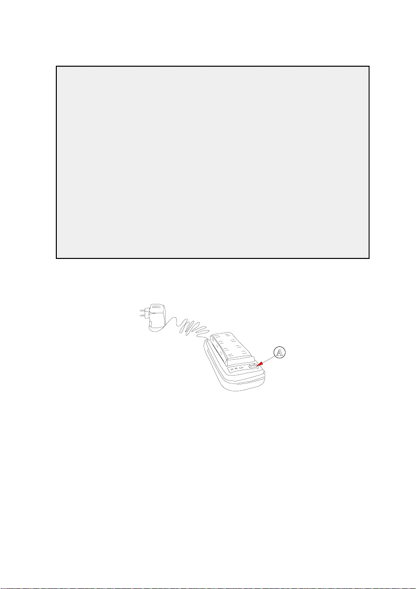
1) Connect the cable from the mains adapter to the charger. Connect the
once
adapter to the mains. Insert the battery in the charger
charger
Discha rge the ba tte ry prior to carrying out the charging process
2)
is connecte d to the ma ins
.
the adapter-
in order to
eliminate any possible residual charge. In order to do so, press button A
situated on the right (see figure 1). At this point, a small yellow light com es
on and the process of discharging is under way. When discharging is
completed, the charger automatically sets the process of charging
underway.
3) The
charging process
lasts for two and a half hours. When the process is
completed, the three red indicators will light up. At the same time, an
indicator will flash and an acoustic alarm will sound for 90 seconds,
indicating that the charging process has been successfully completed.
4) After this period, if the battery is not removed from the charger it will remain
in permanent
minimum char g e mode.
A green LED will flash until the battery
is removed.
Page 8
CAUTION
1) Before using the charger, make sure that the adapter is suitable for the
ma ins volta g e . A n in dica to r will light u p wh e n the a da p te r is c onnecte d to
the ma ins and the cha rger is conne cted.
2) This charger is de signed for cha rging Ni-C d ba tteries.
3) In order to prolong the lifetime of the batteries, it is advisable not to remove
it from the ch a rge r wh ile the ch a rging proc e ss is still unde r way.
4) The ma ins a dapte r and the ba ttery cha rger a re de signed for indoor use.
5) When using the batte ry first time, it is advisable to carry out two charging
and discha rging processes into the charger itself, in order to e liminate any
possible memory effect, accumulated during the period it has been in
storage.
Figure 1.-
CB-410 battery charger and mains adapter.
Page 9
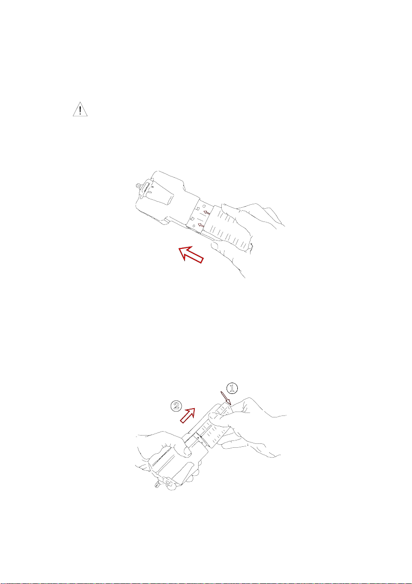
3.2 Installing the battery
Atta ching the batte ry
CB-038
Use
batteries only.
To attach the battery, position it on the base of the arrows found on the back
of the instrument. Slide the battery until you hear a click and it remains fixed,
as shown in the figure 2.
Figure 2.-
Re moving the ba ttery
Installation of the CB-038 battery.
The battery is accessible from the back of the instrument. To disconnect the
battery, press the tab found at one end of it (1) and move the battery to
separate it from the body of the instrument (2). The battery will be released
from its holder. Then slide the battery out, as shown in figure 3.
Figure 3.-
Removing the battery.
Page 10

3.3 Installation and start-up
PROMAX-6
The
battery is installed and the instrument is connected, the version of the instrument
and the channel plan which it has stored will appear on the display for a few
moments.
When this indication appears, the instrument is in channel tuning mode. By
means of the program RM-006, one c an select the starting up of the instrument in
one of the three tuning modes: FREQ or CHAN.
When the ON/OFF key [12] is pressed, the instrument is then in "automatic cutoff" mode; in other words, the device is automatically disconnected when twelve
minutes in operation have gone by without a key being pressed.
The automatic cut-off mode c an be deactivated by holding down the ON/O FF
key for one or two seconds when the device is connected. The indicator "manual
power off" will appear on the display.
has been designed for use as portable equipment. When the
If the battery is low (at a voltage of less than 6.5 V ), a blinking
message will appear on the display [3]. When the v oltage is lower than 6.0 V, the
instrument disconnects.
A fully charged battery can power the equipment non-stop for more than an
hour and a half. At 30% stop/start of intermittent operation, the battery can power
it for up to five hours. When the LOW BATTERY indicator appears, the battery must
be recharged.
When a fully discharged battery is installed, it is possible that, due to residual
charges, the
automatically disconnect before the message LOW BATTERY appears on the display.
PROMAX-6
may start up. In this case, the instrument will
LOW BATTERY
Test Equipment Depot - 800.517.8431 - 99 Washington Street Melrose, MA 02176
FAX 781.665.0780 - TestEquipmentDepot.com
Page 11
4 OPERATING INSTRUCTIONS
4.1 Description of the controls and elements
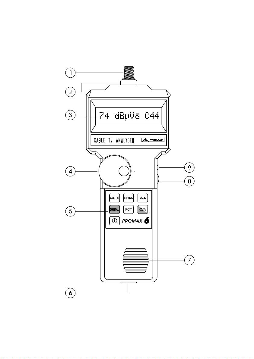
Front P ane l
Figure 4.-
Front view.
Page 12

[1]
F-F (or F-BNC or F-IEC) adaptor
Maximum input voltage level 60 VAC rms /50-60 Hz
[2]
[3]
[4]
[5]
[6]
[7]
[8]
[9]
"F" male base connector
Alphanumeric display with back lighting. Indicates the level, the
measurement mode (analogue or digital channels), tuning (frequency /
channel), the sound system and the measurements of the video/audio
and carrier/noise ratios.
Rotary switch. Used for continuous tuning control or for selecting the
various options associated with each key.
Keyboard. Seven keys for selecting the functions
Connection to computer (for option RM-006)
0CA2170 specific connection cable supplied with option RM-006
Do not connect any cable other than that supplied by the
manufacturer with option RM-006, otherwise the instrument may
suffer serious da mage .
Loudspeaker
Volume control
External headphones connector
Page 13

Figure 5.- PROMAX-6
keyboard
[10]
Measurement selector for analogue channels. When this measurement
mode is selected, an "
a
" appears on the display to the right of the units.
[11]
Measurement selector for QAM modulated digital channels. When this
measurement mode is selected, an "
of the units.
d
" appears on the display to the right
[12]
ON/OFF. Connects / disconnects the instrument and allows the user to
select automatic or manual cut-off.
[13]
Special functions
F1: Sound AM / FM / LEVEL / OFF
F2: Sound subcarrier tuning from 4 - 9 MHz
F3: Frequency shift with respect to the main frequency for measuring
the C/N ratio on digital channels.
Page 14

[14]
Measurement of the carrier/noise ratio on analogical ("a") and digital ("d")
channels. Press this key to m easure the carrier-to-noise ratio of the signal,
once the video carrier level is stabilized.
[15]
Measurement of the video-to-audio ratio (only on analogue channels). Press
this key to measure the video-to-audio ratio of the signal, once the video
carrier level is stabilized.
[16]
Tuning mode: frequency or channel. Press this key to select among tuning
by frequency or channel.
Page 15

4.2 Operating instructions
4. 2.1 T uning mode se lection
PROMAX-6
The
has two different tuning modes:
By freque ncies
By channe ls
To pass from one mode to the other push the
Example 1:
This procedure can be useful in discovering the real frequency in MHz of the
selected channel. The example illustrates finding the frequency which corresponds
to channel 44.
: From 5 to 862 MHz in steps of 62.5 kHz, using the rotary switch.
The values displayed are given in MHz, with a two-decimal
resolution.
: The channel plan in the CCIR standard or may be established
under request (OPT-006-61), or be configured by the user
(RM-006), with a maximum of 239 channels.
CHAN
key [16].
Changing from channel mode to frequency mode.
Test Equipment Depot - 800.517.8431 - 99 Washington Street Melrose, MA 02176
FAX 781.665.0780 - TestEquipmentDepot.com
Page 16

Example 2:
To change the frequency value from 62.25 MHz up to 850 M Hz.
Due to the high resolution of the instrument (62.5 kHz) it is not very efficient to
move through all the bands in frequency mode. A satisfactory solution is to use the
channel mode to make substantial changes in frequency, as is shown in the
example below.
C69
The selection of the channel situated in a frequency close to the desired
frequency.
850.25
Note:
When changing from frequency to channel, if the frequency tuned does not
correspond to any channel, the
PROMAX-6
will search for the channel nearest to
this frequency and will remain tuned to this channel. This operation may take
several seconds.
Page 17

4. 2.2 M ea sureme nt mode : Analogue or digital cha nnels
The
ANALOG
[10] and
DIGITAL
[11] keys can be used to define the type of
channel to be measured: analogical or digital, respectively.
a
When the analogical channel measurement mode is selected, an '
' appears on
the display to the right of the units. Likewise, when the digital channel
d
measurement mode is selected, a '
' appears on the display to the right of the
units.
The measurements possible for each type of channel are as follows:
Analogue channe ls
: - Carrier level meter
- Carrier to Nois e (C/N) ratio meter
- Video/Audio (V/A) ratio meter
Digital cha nnels
: - Channel power meter
- Carrier to Nois e /C/N) rati o meter
Note: Channel denomination and frequency can be m odified via the PC using
the RM-006 software.
Page 18

4. 2.3 M ea sureme nts on ana logue cha nnels
4. 2.3 .1 Ca rrier leve l mea sureme nt (a nalogue cha nnels)
- Select the analogue channels measuring mode as it is explained in point 4.2.2.
- Select the desired tuning mode and tune the signal to be measured in the
manner explained in point 4.2.1.
- Wait until the measured value is stabilized. Read the value shown on the
display. The units will be given in dBµV (dBmV using the option OP T-006-61,
or by means of the customization program RM-006).
- The direct read range of the instrument is from 25 to 120 dBµV, and within this
range the measurement is completely automatic. The microprocessor calculates
the attenuation value corresponding to the proper measurement range. When
the signal level being measured is lower/equal than the sensitivity or
higher/equal than the saturation level of the instrument, the symbols "<" or ">"
will appear, respectively.
- When the tuning is carried out by channels, it is possible that the broadcasting
station deviates a few kHz with respect to the channel frequency. If this
variation is higher than 40 kHz, tune again using this time the frequency mode,
to obtain a more correct level reading.
Example 3.
Measuring the video carrier level in channel 21 (CCIR standard).
C21
Page 19

Example 4.
Measuring the commercial FM carrier (105.00 MHz)
S01
Channel S01 is nearest to the desired frequency
105.00
Example 5.
Measuring a signal outside the measurement range. The sound
subcarrier in channel 44 (655.25 MHz + 5.5 MHz = 660.75 MHz).
* The noise level of the instrument is situated between 5 and 7 dBµV. T his means
that the instrument can measure signals between 10 and 20 dBµ V. The sign "<"
appears to indicate that in this area it is possible that specified accuracy may not
be complied with, but in most cases a measurement valid for all purposes is given.
Page 20

4. 2.3 .2 M ea sure of the V / A ratio (ana logue cha nnels)
This function allows the user to measure the ratio of the signal levels of the
video carrier of an analogue channel and the corresponding audio carrier of the
same channel. In addition, there is an automatic demodulation of the sound in FM
or AM, in accordance with the option selected, as explained in Point 4.2.5.1.
Follow the steps below to take this measurement:
1) Select the analogue channels measuring mode
2) Tune the desired video carrier and wait a few seconds until the read level
is stabilized.
V/A
3) Press the
4) Wait until the measurement is s tabilized (3 seconds maxim um)
[15] key
Example 6
. Measuring the V/A ratio for the following signal
Video frequency = C55 (743.25 MHz)
Video carrier level = 74 dBµV (14 dBmV)
Audio subcarrier frequency = 5.5 MHz
Audio carrier level = 64 dBµV (4 dBmV)
Leave the V/A mode simply by press ing any key or turning the rotary switch.
Test Equipment Depot - 800.517.8431 - 99 Washington Street Melrose, MA 02176
FAX 781.665.0780 - TestEquipmentDepot.com
Page 21

4. 2.3 .3 M ea sureme nt of the C /N ratio (ana logue cha nnels)
This function allows the user to measure the ratio of the video ca rrier level to
the noise level present in the channel.
Follow the steps listed below to take this measurement.
1) Select the analogue channels measuring mode.
2) Tune the video carrier in the channel and wait a few moments until the read
level is sta bilized.
C/N
3) Press the
[14] key
4) Wait a few seconds until the measurement is stabilized (maximum 10 seconds).
C/N
When the
[14] key is pressed, the instrument automatically takes a s eries
of measurements in order to arrive at the closest approximation to the noise level.
The time of approximation is a function of the content of the picture that is being
transmitted and of the C/N value itself.
When the noise level is lower than the sensitivity of the instrument, a limit value
">" will appear on the display, indicating that the C/N value the user is trying to
measure is greater than this limit value.
Example 7.
Measuring the C/N ratio for the following signal
Video carrier level = 82 dBµV (22 dBmV)
Real C/N ratio = 42 dB
C/N ratio measured = 42 dB ± error (see Appendix E)
Display shown after a 5-second wait.
Leave the C/N mode simply by pressing any key or turning the rotary switch.
- 69 -
Page 22

Example 8.
Measuring the C/N ratio of high-quality signals
Video carrier level = 113 dBµV (53 dBmV)
Real C/N ratio = 62 dB
C/N ratio measured > 50 dB
The C/N measurement ranges and the accuracy of the measurement are
described in Appendix E.
Example 9.
Measuring the C/N ratio of low level signals. (<70 dBµV)
The C/N ratio measurement dynamic is proportional to the video carrier level.
So, when the video carrier level is lower than 70 dBµV, the C/N measurement
dynamic does not surpass 50 dB (see Appendix E). If the C/N ratio to be measured
is higher than this value, the instrument will indicate it by means of the sym bol
Video carrier level = 65 dBµV
Real C/N ratio = 48 dB
C/N ratio measured > 44 dB
>
.
Page 23

4.2.4 Measurement of digital channels
4.2.4.1 Power measurement of digital channels
PROMAX-6
directly provides the power measurement for QAM digital channels
with a bandwidth of 7 or 8 MHz as described below:
- Select digital channel measurement mode in accordance with section 4.2.2.
- Select the desired tuning mode and tune the desired signal in accordance with
section 4.2.1.
- Wait for the measured value to s tabilise. R ead the va le display ed. Un its w ill be
expressed in dBµV (dBmV using option OPT-006-61 or by means of the
personalisation program RM-006).
- The direct reading range covers from 34 up to 129 dBµV and all measurements
within this range are entirely automatic. The microprocessor calculate the
attenuation value for the suitable measurement range. When the signal level to
be measured is lower/equal to the sensitivity or is higher/equal to the
equipment's saturation level, the signs "<" or ">" appear, respectively.
Example 10.
Measurement of power level of a digital channel (D25)
D25
Page 24

4.2.4.2 Measurement of the C/N ratio (digital channels)
The C/N function allows to measure autom atically the ratio between the power
level of the digital channel and the noise level outside the channel being studied.
When pressing the
C/N
[14] key, the
PROMAX-6
automatically measures the
channel power level, the noise level outside the channel (at a lower frequency than
F3
the main carrier and defined through the
function) and shows the value of the
C/N ratio in the display.
Next figure shows that when measuring the C/N ratio it is necessary to c heck
if there is an adjacent channel at the lower frequencies, in order to do not confuse
the noise level with the adjacent channel signal. To select the optimum shift
frequency in each case, function F3 has been incorporated.
An easy way to chec k if there is an adjacent channel at the lower frequencies
consists of making a level measurement at a frequency
8 MHz
lower to the main
frequency of the channel being studied and comparing if level is similar to the
power level of the channel under study (there is an adjacent channel) or the level
drops off significantly (there is no adjacent channel).
As a resume, and taking previous figure as an ex am ple, in the cas e there is no
adjacent channel at the lower frequencies (channels D24 or D27) noise level
measurement should be taken outside the channel at a frequency
4.5 MHz
lower
than the studied channel main carrier. Otherwise, if there exists an adjacent
channel at the lower frequencies (D25 or D26) the best approximation consists of
making the noise level measurement in the separation between the studied channel
and its lower adjacent channel, where the modulation contents is minimum.
Page 25

4.2.4.2.1 F3 function: Frequency shift for the C/N measurements
To select the frequency shift in the C/N measurement, press the
then use the rotary encoder to select the
again. Turn the rotary encoder until the desired shift is displayed. Lastly, press the
FCT
[13] key again to select the shift.
This parameter is defined at factory as
measurements directly when there is no adjacent channel at the lower frequencies.
4.2.4.2.2 Measuring the C/N ratio with no adjacent channels present.
To perform this measurement, proceed as follows:
1) Select the digital channel measurement mode.
2) Tune the main carrier of the channel and wait a few moments until the reading
level stabilises.
3) Select the frequency shift of the noise level measurement by means of the
function to
predetermined at factory for this parameter, so if it has not been modified
through the F3 function it will not be necessary to redefine it now.
4) Press the
5) Wait until the reading stabilises (10 seconds maximum).
When the
automatic measurements so as to come as close as possible to the real value of
the noise level. The time this takes depends on the content of the image that is
being transmitted and the C/N value itself.
4.5 MHz
C/N
C/N
with respect to the main carrier. 4.5 MHz is the value
[14] key.
[14] key is pressed, the equipment performs a series of
F3
function and press the
4.5 MHz
; this shift allows to make C/N
FCT
FCT
[13] key,
key [13]
F3
When the noise level is lower than the equipment's sensitivity, a limit value ">"
is displayed to indicate that the C/N value to be measured is greater than this limit
value.
Test Equipment Depot - 800.517.8431 - 99 Washington Street Melrose, MA 02176
FAX 781.665.0780 - TestEquipmentDepot.com
Page 26

Example 11.
Measurement of the C/N ratio for channel D24 (no adjacent channel).
Channel power level = 74 dBµV (14 dBmV)
Real C/N ratio = 32 dB
Measured C/N ratio = 32 dB ± error (see appendix F)
(D23, channel adjacent to D24)
D.23
(No adjacent channel)
D.24
Display appears after about 5 seconds.
C/N mode can be exited by simply pressing any key or turning the rotary
encoder.
Page 27

4.2.4.2.3 Measurement of the C/N ratio with adjacent channels present
To perform this measurement, proceed as follows:
1) Select the digital channel measurement mode.
2) Tune the main carrier of the channel and wait a few moments until the reading
level stabilises.
3) Select the frequency shift of the noise level measurement by means of the
function to a frequency where the modulation content is minimum (about
4 MHz
).
4) Press the
C/N
[14] key.
5) Wait until the reading stabilises (10 seconds maximum).
Examp l e 12.
Measurement of the C/N ratio for channel D25 (with adjacent channel).
Channel power level = 74 dBµV (14 dBmV)
F3
Page 28

(D24, channel adjacent to D25)
D.24
(Adjacent channel present)
D.25
(Frequency shift selection)
++
F3 4.00
Display appears after about 5 seconds.
Page 29

4.2.5 Function key
The FCT key enables the user to access a menu with 3 configuration functions:
F1, F2
and
F3
(the last one explained in the C/N ratio measurement for digital
channels paragraph).
4. 2.5 .1 F1 function: Sound de modulation
This function selects three kinds of sound demodulation together with the
disconnection of the sound itself.
FM
: FM sound
AM
: AM sound
LV
: The speaker emits a tone whos e frequency varies as a function of
the signal level received.
OFF
: Sound not selected
The demodulation of both AM and FM is effected on the c arrier tuned.
FCT
To select the type of sound, press the
key [13], select the F1 function and
turn the rotary switch until the desired type of sound is displayed. Press the
key [13] again to activate the desired mode.
FCT
Example 13.
Changing the sound from FM to LV
+
LV
Page 30

The diagram below shows the order of selection using the rotary switch of the
FCT (F1) function.
Figure 6.-
4. 2.5 .2 F2 function: Sound subca rrier
This function enables the user to vary the frequency of the sound subcarrier
from 4 to 9 MHz, in 62.5 kHz steps.
This function is necessary if the user wants to vary the frequency of the sound
subcarrier related to the measurement of the V/A ratio (see Point 4.2.3.2). The
instrument takes as the default frequency the value configured in the factory (or a
customized configuration through RM-006). However, with the F2 function the user
can vary the sound subcarrier value manually, from 4 to 9 MHz.
F1 function menu.
Test Equipment Depot - 800.517.8431 - 99 Washington Street Melrose, MA 02176
FAX 781.665.0780 - TestEquipmentDepot.com
Page 31

Example 14
. Changing the sound subcarrier frequency from the standard value to
5.74 (Zweiton Stereo).
+
F2
5.75
Page 32

The diagram below shows the order of selection using the rotary switch of the
FCT (F2) function.
Figure 7.-
Note:
The new value chosen in functions F1, F2 and F3 only remain in the memory
Menu of the F2 function.
until the battery is removed. When the battery is removed the instrument undergoes
a RESET and the values configured through the F1, F2 and F3 functions are lost.
When the battery is reconnected, the instrument adopts the factory-configured
values or those programmed by means of RM -006.
4. 3 C onnection to the com puter
The system may be connected to a PC by means of the connection cable which
is supplied with option RM-006.
Do not connect any c able othe r than that supplied by the ma nufacturer with
op tion RM-006, o therwise s eri o us d am ag e may be c aused to the eq uipmen t.
1) Prior to connecting the equipment to a PC, disconnect both from their
respective power supplies.
2) Connect the end of the connection cable co rresponding to the
PROMAX-6
to connection [6] and the other end to the parallel port of your computer.
(See the RM-006 operation manual for further information).
Page 33

5 MAINTENANCE
This part of the manual describes the maintenance procedures and the
localization of faults.
5. 1 Ins truction s for re turning by m ail
Instruments returned for repair or calibration, either within or outwith the
guarantee period, should be forwarded with the following information: Name of the
Company, name of the contact person, address, telephone number, receipt (in the
case of coverage under guarantee) and a description of the problem or the service
required.
5. 2 M ethod of M ainte nance
The method of maintenance to be c arried out by the user consists of cleaning
the cover and changing the battery. All other operations should be carried out by
authorized agents or by personnel qualified in the servicing of instruments.
5.2.1 Cleaning the cover
CAUTION
To cle an the cove r, re move the ba ttery from its housing.
CAUTION
Do not use scented hydroca rbons or chlorized solve nts. Such products may atta c k
the plastics use d in the construction of the cove r.
The cover should be cleaned by means of a light solution of detergent and
water applied with a soft cloth. Dry thoroughly before using the system again.
CAUTION
To cle an the conta cts, use a dry cloth. D o not use a we t or dam p cloth.
Page 34

APPENDIXES
APPENDIX A
MEASUREMENT OF THE VIDEO CARRIER LEVEL (C
- ANALOGUE CHANNELS-
A) N ega tive V ideo M odulation (P AL/N T SC )
The measurement of the v ideo c arrier level is carried out taking the modulation
peak as the measurement value, this being the maximum value of the signal during
the line synchronism. The system requires a minimum length of time in order to
make this measurement, since it has to detec t the peak of the modulated signal.
)
L
Figure 8.-
Measurement of the video carrier level.
The typical values between which the video carrier level fluctuates are:
- In the transmission line: From 70 to 100 dBµV (From 10 to 40 dBmV )
- In the user's terminal: From 60 to 80 dBµV (From 0 to 20 dBm V)
b) P ositive Vide o M odulation (S EC AM )
On this type of modulation, the line synchronism is defined by a minimum
carrier level. The maximum signal level (measurement point) is variable in time,
and it is a function of the picture that is being transmitted. It could vary from 10 dB
among white and black image; nevertheless white signals, Video Insertion Test
(VIT), are transmitted in the sweep pulses, which reduce this margin to 4 dB
approximately.
Due to this fact, and the small duration of the V IT, when we m easure levels of
SECAM signals, it is advisable to add 2 dB to the quantity showed on the display,
in order to obtain a more precise measurement in its average value.
Page 35

APPENDIX B
MEASUREMENT OF THE ADJACENT CHANNEL LEVEL
The user can obtain the ratio of the video carrier amplitudes of two consecutive
channels.
C
VL1
- C
VL2
(dB)
Figure 9.
Measurement of the adjacent channel level.
Differences of more than three dB between carriers of adjacent channels may
cause problems of interference in reception.
Test Equipment Depot - 800.517.8431 - 99 Washington Street Melrose, MA 02176
FAX 781.665.0780 - TestEquipmentDepot.com
Page 36

APPENDIX C
MEASUREMENT OF THE RELATIVE VIDEO / AUDIO LEVEL (V/A) -ANALOGUE
CHANNELS-
V / A = AL - VL (dB)
The user can measure the existing ratio of the amplitudes of the video-to-audio
carriers.
Although this process depends on the standard used, it is usual to consider that
a properly transmitted PAL channel should have a sound subc arrier 13 dB below
the video carrier.
Figure 10.-
Measurement of the relative video/audio ratio.
These specifications ensure that there is no interference in the same or the
adjacent channel.
Page 37

APPENDIX D
CARRIER NOISE MEASUREMENT (C/N) -ANALOGUE CHANNELS-
The carrier-to-noise ratio is a measurement of the signal quality. The power of
the noise measured changes according to the resolution filter utilized. However, in
TV it is usual to refer the noise level to a bandwidth of 5 M Hz. If the meas urement
is reduced to a different bandwidth, the user must apply a s imple correction. The
PROMAX-6
takes the measurements in a noise bandwidth of 5 MHz .
C/N = C
: depends on the measurement bandwidth
N
L
= N
N
L
measured L
- NL (dB)
L
+ 10 log (BWx / BW
There is some standards that determine the minimum
40 dB
installation. In general greater values than
signals. Lower than 40 dB you can see "
snow
are considered good quality
" or graininess at the display.
measured
)
C/N
value in an
Page 38

APPENDIX E
CARRIER/NOISE MEASUREMENTS (C/N) -ANALOGUE CHANNELS-
Example:
Suppose that the video carrier level in a channel, for instance the 45,
is of 25 dBmV, from the diagram we can deduce that the measurement
range is of 45 dB.
Thus, if when we carry out the measurem ent the C/N ratio is 54 dB the
display will show.
on the other hand, if C/N=42 dB we will see on the display:
Page 39

APPENDIX F
CARRIER TO NOISE RATIO FOR 64-QAM DIGITAL CHANNELS (C/N)
For a 64-QAM DB V-C digital signal with a bandwidth of 8 MHz, the C/N ratio
20 dB
must be better than
. Measurements lower than this value will correspond to
signals with a no acceptable quality.
Justification and ex ample
The basic parameter which describes the quality of a digital signal is the ratio
of the number of erroneous bits to the total number of bits transmitted. This
BER
parameter is known as
The DBV Group (Digital Video Broadcasting) defines a '
transmission'
(ETR290 Measurements Group ETR 290) as that with less than 1
(Bit Error Ra te).
quasi error free
error event per transmission hour. For a 64 QAM DBV-C transmission, the pre-FEC
error (Forward Error Correc tion) must be <1.E-4.
In digital transmissions, as there is not one carrier, it is better to speak in E
terms. The relation between Eb/No and the C/N is given by the following equation:
b/No
Where :
E b = E nergy per bit
= Noise power in a 1 Hz bandwidth
N
o
= Symbol rate
R
s
M = Num ber of points of the constellation
BW = Bandwidth
For DVB-C, 64 QAM, Rs=6.875 M baud, BW=8 MHz,
C/N (dB) =E
For a BER of 1E-4, E
/ No (dB) + 7.12.
b
≈ 16 dB. Therefore C/N ≈ 23 dB.
b/No
09/97 PROMAX-6- 88 -
Test Equipment Depot - 800.517.8431 - 99 Washington Street Melrose, MA 02176
FAX 781.665.0780 - TestEquipmentDepot.com
 Loading...