

Page 1

99 Washington Street
Melrose, MA 02176
Phone 781-665-1400
Toll Free 1-800-517-8431
PROMAX-27
CABLE TV & DATA ANALYSER
- 0 MI1546 -
Page 2

NOTAS SOBRE SEGURIDAD
Antes de manipular el equipo leer el manual de instrucciones y muy
especialmente el apartado PRESCRIPCIONES DE SEGURIDAD.
El símbolo
INSTRUCCIONES". En este manual puede aparecer también como símbolo de
advertencia o precaución.
Recuadros de ADVERTENCIAS Y PRECAUCIONES pueden aparecer a lo largo de
este manual para evitar riesgos de accidentes a personas o daños al equipo u
otras propiedades.
sobre el equipo significa "CONSULTAR EL MANUAL DE
SAFETY NOTES
Read the user’s manual before using the equipment, mainly " SAFETY RULES "
paragraph.
The symbol
may also appear as a Caution or Warning symbol.
Warning and Caution statements may appear in this manual to avoid injury
hazard or damage to this product or other property.
on the equipment means "SEE USER’S MANUAL". In this manual
REMARQUES À PROPOS DE LA SÉCURITÉ
Avant de manipuler l'appareil, lire le manuel d'utilisation et plus particulièrement le
paragraphe "PRESCRIPTIONS DE SÉCURITÉ".
Le symbole
Dans ce manuel, il peut également apparaître comme symbole d'avertissement ou de
précaution.
Des encadrés AVERTISSEMENTS ET PRECAUTIONS peuvent apparaître dans ce
manuel pour éviter des risques d'accidents affectant des personnes ou des dommages
à l'appareil ou à d'autres biens.
sur l'appareil signifie "CONSULTER LE MANUEL D'UTILISATION".
Page 3

USER’S MANUAL. PROMAX-27
TABLE OF CONTENTS
GENERAL.................................................................................................................. 1
1
1.1 Description .......................................................................................................1
1.2 Specifications ................................................................................................... 2
2 SAFETY RULES........................................................................................................ 7
2.1 Generals...........................................................................................................7
2.2 Descriptive Examples of Over-Voltage Categories .......................................... 8
3 INSTALLATION .........................................................................................................9
3.1 Power Supply ...................................................................................................9
3.1.1 Charging the battery ..................................................................................... 9
3.1.2 Recommendations using the battery .......................................................... 10
3.2 Installation and putting in operation ...............................................................10
3.2.1 Adjusting contrast ....................................................................................... 10
4 OPERATING INSTRUCTIONS................................................................................ 11
4.1 Description of the controls and elements ....................................................... 11
4.2 Operation Instructions ....................................................................................13
4.2.1 SETUP Mode ..............................................................................................15
4.2.2 CONFIG Mode ............................................................................................17
4.2.2.1 EDIT CHANNEL PLAN......................................................................... 19
4.2.3 MODEM Mode ............................................................................................21
4.2.3.1 CONSTELLATION DIAGRAM (IQ).......................................................23
4.2.3.2 SEARCH function ................................................................................. 25
4.2.3.3 SCAN function ...................................................................................... 27
4.2.3.4 SPECTRUM function............................................................................ 28
4.2.3.5 LOGGER function................................................................................. 30
4.2.3.6 TILT function......................................................................................... 33
4.2.4 REGISTERED Mode — IP NETWORK Functions ....................................... 34
4.2.4.1 VoIP...................................................................................................... 35
4.2.4.2 IPTV...................................................................................................... 37
4.2.4.3 PING..................................................................................................... 39
4.2.4.4 TRACEROUTE..................................................................................... 41
4.2.5 TV Mode ..................................................................................................... 43
4.2.5.1 TV DIGITAL mode ................................................................................44
4.2.5.1.1 CONSTELLATION DIAGRAM function.......................................... 45
4.2.5.2 ANALOGUE mode................................................................................ 47
4.2.5.2.1 AUDIO function ..............................................................................48
4.2.5.3 SLM mode ............................................................................................50
4.2.5.4 COMMON FUNCTIONS in TV mode ................................................... 51
4.2.5.4.1 SCAN function................................................................................ 51
4.2.5.4.2 SPECTRUM function .....................................................................52
4.2.5.4.3 LOGGER function ..........................................................................53
4.2.5.4.4 TILT function ..................................................................................56
4.2.6 TEST SIGNAL GENERATOR mode........................................................... 57
4.3 CONNECTING TO DEVICES. .......................................................................58
5 MAINTENANCE....................................................................................................... 59
5.1 Instructions for returning by mail .................................................................... 59
English
Page 4

USER’S MANUAL. PROMAX-27
Method of maintenance.................................................................................. 59
5.2
5.2.1 Cleaning the cover. .....................................................................................59
5.3 Components which user can not replace ....................................................... 60
5.3.1 Not replaceable fuses by user .................................................................... 60
APPENDIXES ................................................................................................................61
APPENDIX A.- MEASUREMENT OF THE MODULATION ERROR RATIO (MER). ... 61
APPENDIX B.- PRINCIPLE OF QAM MODULATION. THE CONSTELLATION
DIAGRAM ................................................................................................................ 63
APPENDIX C.- FREQUENCY OFFSET ADJUSTMENT FOR TUNING ANALOGUE
AND DIGITAL CHANNELS...................................................................................... 65
Page 5

USER’S MANUAL. PROMAX-27
TV CABLE / DATA ANALYSER
PROMAX-27
1 GENERAL
1.1 Description
The PROMAX-27 is a portable analyser for the configuration, installation and
maintenance of interactive video services and high-speed data networks over TV
coaxial networks based on DOCSIS 2.0 and EuroDOCSIS standard. On the other
hand, can also analyse services based on IP protocol transmitted by these same
networks, such as Voice IP, IPTV or the Internet.
The PROMAX-27 has all the functions necessary for an easy installation of any
service offered by cable. In addition, its intuitive menu, its adjusted weight and strength,
makes it ideal for fieldwork. The instrument is powered by an internal rechargeable
battery.
In the design of the PROMAX-27 it has dedicated particular attention on making a
practical and precise instrument, as easy to use. A simple alphanumeric keypad that
incorporates soft-keys allowing direct access to different modes of operation and once
there, through the ambidextrous navigation and selection keys it's easy to modify any
parameter of the measure.
All this makes the PROMAX-27 in a magnificent tool for installing and maintaining
HFC (Hybrid Fibber Cable) / CATV, analog and digital systems. Being also very useful
for testing DOCSIS / EuroDOCSIS data transmission systems.
In addition, the instrument provides a serial output for connecting to a printer or
computer and thus obtains reports of the taken measures or access the PROMAX
server for updating.
Here are some of the most important functions the PROMAX-27 integrates.
The Power meter function, across the frequency band, is very useful in
assessing the possible saturation of inputs of CATV amplifiers.
The Meter Level function will take measures both analog channels (C / N ratio,
level of carrier, V / A ratio) and digital (Power, VER, MER, Constellation ...).
The Register function allows you to take and store up to 100 measurements
acquisitions in memory, each one of them can get to store up to 140 channels, with all
the measurements taken in the analysis of data transmission. The acquired measures
can be reviewed, transferred to a PC or printed anytime.
English
07/2008 Page 1
Page 6

USER’S MANUAL. PROMAX-27
The Frequency Scan function shows the level of all active channels in the
channel plan through a bar chart.
By the Generator Function, it is possible to create a test signal that allows you to
equalize properly the transmission band (upstream).
As Spectrum Analyser function provides an analysis of the whole band, allowing
change the reference level and the span among others.
As Analyser Data Systems for DOCSIS / EuroDOCSIS, the PROMAX-27 allows
you to measure downstream, upstream and the constellation.
The VoIP function performs a network analysis based on quality service
parameters established by the operation mode UGS (Unsolicited Grant Service) for data
packets transmission, which is based on DOCSIS / EuroDOCSIS standard. Therefore,
those will ensure the best call quality.
PROMAX-27, as IPTV services analyser, performs a comprehensive analysis of
the network based on the quality of service (QoS) named rtPS (real time Polling
Service), which is one of the quality services defined by DOCSIS / EuroDOCSIS
standard. That will ensure the best quality of TV over cable.
The PING function performs an analysis of standard Internet traffic, such as
browsing websites, emails or instant messaging. To check the quality of service, it uses
the quality of service defined as BE (Best Effort) based on the standard DOCSIS /
EuroDOCSIS.
In short, implementation of all these functions into an light instrument of one kilo
and a half weight, ergonomic design and robust, makes PROMAX-27 into an
unparalleled tool at fieldwork.
1.2 Specifications
TUNING
Tuning range From 5 to 862Hz.
MODEM mode From 53 to 855 MHz
Tuning mode By channels or by frequency.
Channel plan 10 channel plans, each one with a maximum of 140
channels. Factory start-up channel plans:
CCIR, EIA, HRC, IRC, OIRL, UK, AUNAD, ST2L,
AUST, ONO.
Resolution 10 kHz.
Indication Graphic LCD display with automatic back lighting.
Channel frequency offset ± 2,5 MHz.
GENERATOR
Carriers frequency range 5 — 60 MHz
Resolution 100 kHz
Page 2 07/2008
Page 7

USER’S MANUAL. PROMAX-27
Accuracy < ± 5 kHz.
Carrier level 60 to 112 dBµV (selectable in 1 dB steps).
Signal level resolution 1 dB.
Signal level accuracy 3 dB.
Modulation QPSK, 8QAM, 16QAM, 32QAM, 64QAM.
Symbol Rate from 160 to 5120 ksym/s.
BROADBAND POWER
LEVEL MEASUREMENT
Measuring range From 70 to 120 dBµV (From 10 dBmV to 60 dBmV
1
).
Bandwidth From 5 to 1000 MHz.
Resolution 1 dB.
Accuracy ± 3 dB (From 5 to 40 °C).
LEVEL MEASUREMENT
Measurement
Analogue channels Video carrier signal level measurement .
Digital channels Power measurement in the channel bandwidth by
integration method.
Measuring range From 25 to 120 dBµV. (From -35 dBmV to 60 dBmV)
Maximum input level
From 5 to 862 MHz 120 dBµV. (60 dBmV
1
)
DC to 60 Hz 60 V DC or RMS
Readout Digital in dBµV, dBmV or dBm and analogue
through a graphic bar. 1 dB resolution
IF bandwidth 230 kHz ± 50kHz
Input impedance 75 Ω
Accuracy
Analogue channels ± 2 dB (from 5 to 40 °C) for negative video
modulation
2
Digital channels ± 3 dB (from 5 to 40 °C) for 8 MHz bandwidth
channels.
DIGITAL SIGNALS MEASUREMENT
MER (Modulation error ratio)
Measurement range 22 dB to 42 dB for QAM 64 / 256.
Accuracy ± 2 dB.
BER (Bit error rate)
Measured before RS decoding
Measurement range 10 E-2 to 10 E-10.
English
1
Because of safety reasons, the maximum input power over the entire band is limited up to 120
dBµV. The equivalent power level for a group of channels of similar levels is related with the
input power level over the entire band according to the following expression:
LT = L+10 log N (LT: total level , L: mean level of one channel, N: number of channels present).
For higher input power levels, the use of an external attenuator of 20 dB is recommended.
2
For the positive video modulation (L standard) it can vary from 0 to -2 dB among white and
black image.
07/2008 Page 3
Page 8

USER’S MANUAL. PROMAX-27
Constellation Diagram ITU-J83 (Annex A/B/C) and DOCSIS/EuroDOCSIS
compliant signals.
Lock range -10 dBmV to 60 dBmV.
Symbol rate
Measurement range 1000 to 7000 Msym/s for QAM 16/64/256.
Datalogger Power level, BER, MER and constellation diagram
can be stored, for data dumping to printer or PC.
Modulation type QAM 16/32/64/128/256 ITU J83 annex A/B/C and
QPSK.
Bandwidth Selectable.
Frequency tuning 62.5 kHz.
VIDEO / AUDIO RATIO MEASUREMENT (ANALOGUE CHANNELS)
Measurement Ratio of video to audio carrier levels.
Measurement range From 0 to 30 dB
Audio subcarrier frequency
Variable 0.1 — 9.9 MHz.
Accuracy ± 2 dB (from 5 to 40 °C) for FM audio carrier
3
.
CARRIER / NOISE RATIO MEASUREMENT
Measurement
Analogue channels Ratio between carrier level and the channel's noise
level.
Digital channels Ratio between the channel power and the noise
level. The frequency where noise is measured is
user definable in absolute or relative value. In the
relative mode, the unit takes as default frequency
offset the value BW/2 + 0.5 MHz.
Measurement range
Analogue channels 40-50 dB for input level between 60 and 70 dBµV.
> 50 dB for input level > 70 dBµV.
Digital channels > 30 dB for input level > 60 dBµV.
Accuracy ± 2 dB (45 — 862 MHz) ± 3 dB (5 — 45 MHz).
CABLE MODEM
DOCSIS / EuroDOCSIS 1.0, 1.1, 2.0.
TV/MODEM DATALOGGER FUNCTION
Max. number of loggers 50 (TV) - 30 (MODEM).
Number of channels/logger 140.
Measurements
TV analogue channels Level, C/N and V/A.
TV digital channels Power, BER and MER.
Data digital channels Upstream and Downstream parameters (Power
level, attenuation, frequency, bandwidth,
modulation, symbol rate, BER, MER and
constellation diagram).
3
For the AM audio carrier (L standard), it can vary from 0 to -3 dB below the V/A value.
Page 4 07/2008
Page 9

USER’S MANUAL. PROMAX-27
SCAN
Span Variable: 10, 30, 100, 300 MHz and full band (from
Dynamic range Variable from 20 to 120 dBuV in 10 dB steps
SPECTRUM ANALYSER
Span From 1 to 100 MHz (1, 5, 15, 30, 50, 100 MHz).
Reference level Variable from 20 to 120 dBµV in 10 dB steps.
Analysed band From 5 to 862 MHz.
Detector Peak or average.
Bandwidth 200 kHz.
Resolution
Peak detector
Span 100 MHz 900 kHz.
Span 50 MHz 450 kHz.
Span 30 MHz 280 kHz.
Span 15 MHz 140 kHz.
Span 5 MHz 50 kHz.
Span 1 MHz 10 kHz.
Average detector
Span 30 MHz 280 kHz.
Span 15 MHz 140 kHz.
Span 5 MHz 50 kHz.
Span 1 MHz 10 kHz.
AUDIO
Demodulation AM/FM.
Output Internal loudspeaker.
POWER SUPPLY
Li-Ion battery 7.4 V — 4.8 Ah.
Low battery indication Graphic indication on the display:
Autonomy Approximately 3 hours.
Automatic power-off Power-off after approximately 10 minutes of non-
Battery charge By fast internal charger.
Equipment consumption 22 W.
Mains to charger adapter Al-103: 100 to 240 V AC / 50-60 Hz / 12 V DC
ENVIRONMENTAL CONDITIONS
This equipment could be used on the following environmental conditions, on
these conditions the specifications could be also applied:
Altitude Up to 2000 metres.
Temperature range From 5 °C to 40 °C.
Maximum relative humidity 80 % (up to 31 °C),
decreasing lineally up to 50 % at 40 °C.
5 to 862 MHz depending on channel plan).
.
use.
(EUROPE and other countries).
English
07/2008 Page 5
Page 10

USER’S MANUAL. PROMAX-27
MECHANICAL FEATURES
Dimensions 160 W x 230 H x 50 D mm.
Weight 1.4 kg. (including battery and protective bag).
INCLUDED ACCESSORIES
AL-103 DC external adapter
AA-12 Car lighter adapter cable
AD-057 F/female - F/female input adapter.
AD-058 F/male - F/female rapid adapter.
CC-030 F/male - F/male (1m) coaxial cable.
0 FD0462 Protective bag.
CA-005 Mains cord
OPTIONAL ACCESSORIES
AD-055 F/female - BNC/female adapter.
AD-056 F/female - IEC/female adapter.
CI-023 Portable serial printer.
CC-209 Data transfer cable to PC or printer.
RM-027 Remote control software for PROMAX-27.
AT-20C 20 dB attenuator.
RECOMMENDATIONS ABOUT THE PACKING
It is recommended to keep all the packing material in order to return the
equipment, if necessary, to the Technical Service.
Page 6 07/2008
Page 11

USER’S MANUAL. PROMAX-27
2 SAFETY RULES
2.1 Generals
* The safety could not be assured if the instructions for use are not closely
followed.
* Use this equipment connected only to devices or systems with their common
at ground potential.
* This equipment can be used in Over-Voltage Category I installations and
Pollution Degree 2 environments.
Use the mains adapter in Over-Voltage Category II installations and Pollution
Degree 1 environments. It is for INDOOR USE.
* When using some of the following accessories use only the specified ones to
ensure safety.
Power adapter
Car cigarette lighter adapter
Mains cord
* Observe all specified ratings both of supply and measurement.
* Use this instrument under the specified environmental conditions.
* The user is not authorised to manipulate inside the instrument:
Any change on the equipment should be carried out by qualified personnel.
* Follow the cleaning instructions described in the Maintenance paragraph.
English
07/2008 Page 7
Page 12
USER’S MANUAL. PROMAX-27
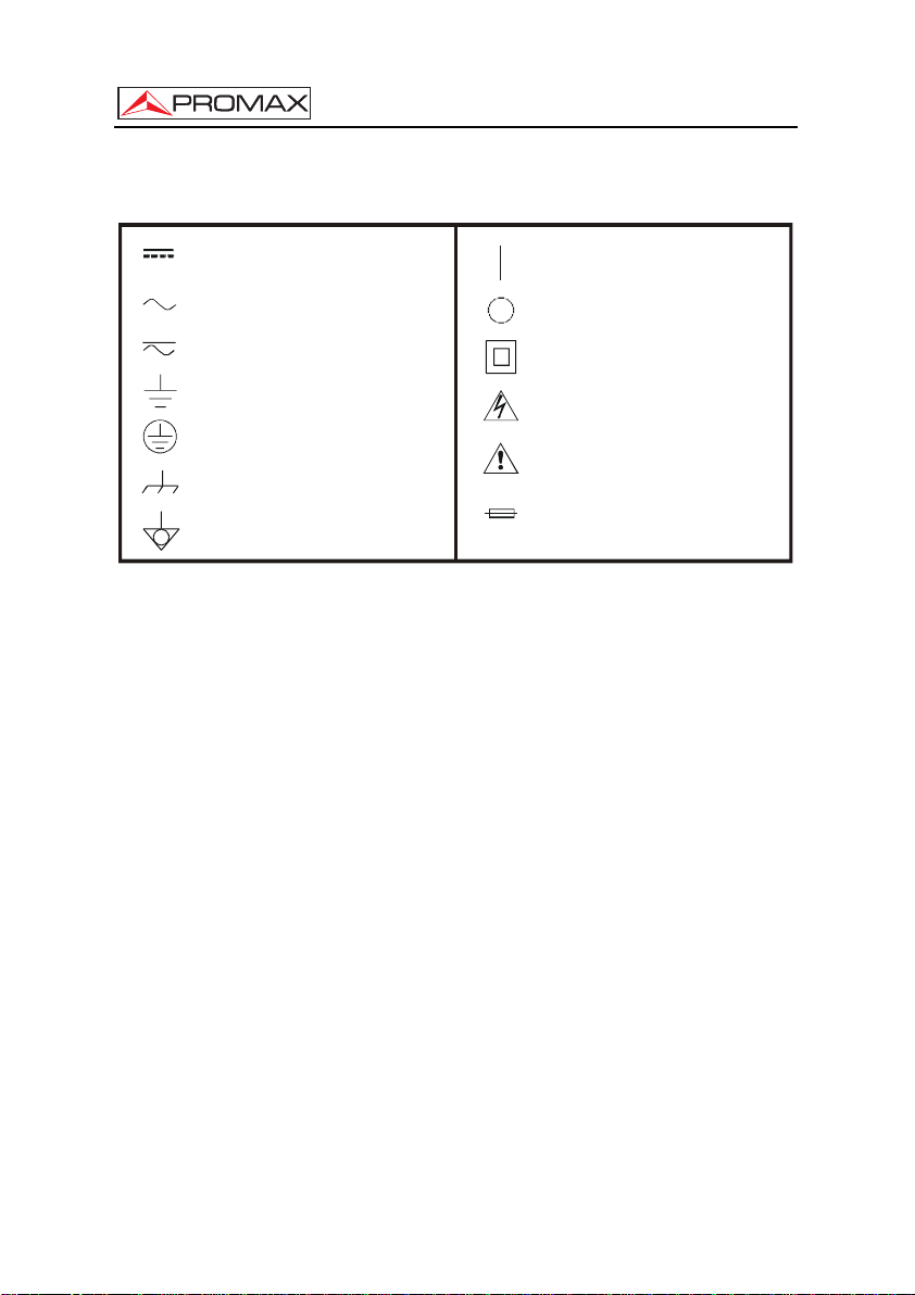
* Symbols related with safety:
DIRECT CURRENT
ALTERNATING CURRENT
DIRECT AND ALTERNATING
GROUND TERMINAL
PROTECTIVE CONDUCTOR
FRAME TERMINAL
EQUIPOTENTIALITY
ON (Supply)
OFF (Supply)
DOUBLE INSULATION
(Class II protection)
CAUTION
(Risk of electric shock)
CAUTION REFER TO MANUAL
FUSE
2.2 Descriptive Examples of Over-Voltage Categories
Cat. I Low voltage installations isolated from the mains.
Cat. II Portable domestic installations.
Cat. III Fixed domestic installations.
Cat. IV Industrial installations.
Page 8 07/2008
Page 13

USER’S MANUAL. PROMAX-27
3 INSTALLATION
3.1 Power Supply
The PROMAX-27 is a portable instrument supplied by a built-in Li-Ion battery.
Before taking any measurement, we must ensure that the battery is charged.
3.1.1 Charging the battery
The instrument is supplied with a mains adapter in order to power or charge the
instrument.
There are two situations that can arise in the battery charging process:
1) Stopped Instrument: When connecting the external power it will start a rapid
charging cycle, whose duration will depend on the battery status. It will take three
hours for a discharged battery. The charging indicator on the front panel [10] will
remain lit in amber colour during this period. At the end of charging and in full
charge, the indicator will be green.
2) Instrument in operation: When connecting the charger, it will start a charging
process in a lower regime and therefore longer. At the end of charging and in full
charge, the indicator will change from amber to green colour.
English
PRECAUTION
Figure 1.- PROMAX-27 and mains adapter.
Before using the power adapter, make sure that the adapter is
suitable for the mains voltage.
Test Equipment Depot - 800.517.8431 - 99 Washington Street Melrose, MA 02176
07/2008 Page 9
FAX 781.665.0780 - TestEquipmentDepot.com
Page 14

USER’S MANUAL. PROMAX-27
3.1.2 Recommendations using the battery
If anticipating a long period of inactivity of the instrument, it is advisable to store it
with battery fully charged and at temperatures below 25 °C.
It is advisable in these cases doing every 3 months a cycle of charging /
discharging and a subsequent half charge (i.e. 50 %).
3.2 Installation and putting in operation
The PROMAX-27 has been designed for using as portable equipment.
A fully charged battery can power the instrument for over three hours. When
displaying the low battery indicator on the screen (
When starting up with a very low level battery, may be the PROMAX-27 could
start up, because of residual energy remaining at the battery, but the equipment will be
disconnected automatically BEFORE displaying on the screen the low level battery
indicator.
), the battery must be recharged.
3.2.1 Adjusting contrast
LCD Adjustment contrast is done via the dial (see Figure 2.- [5]) located at the
right side panel of the instrument.
By turning the dial is possible to adjust the screen contrast to get the best display
in any environmental condition. By turning counter-clockwise, the contrast decreases.
By turning clockwise, it increases. The new value of contrast is kept when the
instrument turns off.
Page 10 07/2008
Page 15
USER’S MANUAL. PROMAX-27
4 OPERATING INSTRUCTIONS
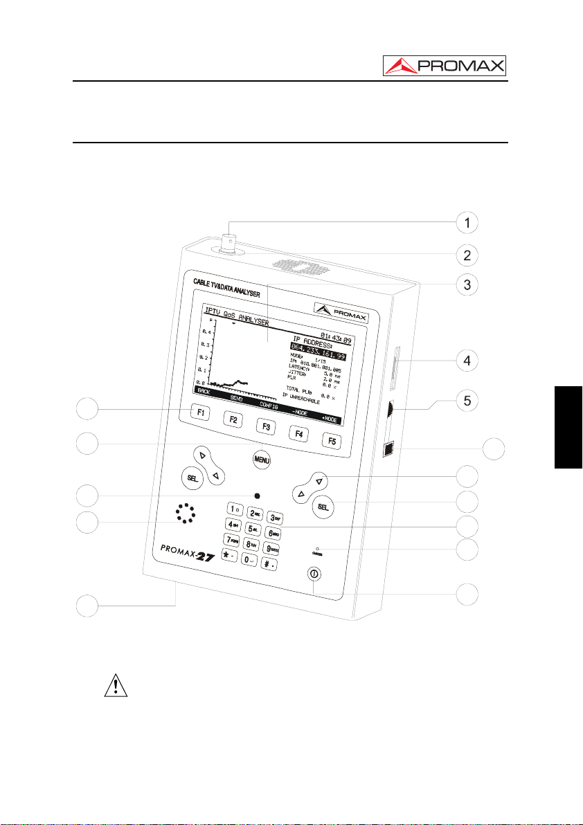
4.1 Description of the controls and elements
Front panel
12
13
6
7
14
15
8
9
10
11
16
Figure 2.- Front panel view.
[1] F-F (or F-BNC or F-IEC) adapter.
Maximum input voltage level 60 VAC rms / 50-60 Hz.
[2] "F" male base connector.
[3] Graphic display with back lighting.
07/2008 Page 11
English
Page 16
USER’S MANUAL. PROMAX-27
[4] Connection to computer or printer.
CC-209 specific connection cable.
Do not connect any cable different than the one supplied by the
manufacturer, otherwise the instrument may suffer serious damage.
[5] Contrast Adjustment
[6] LAN connector (ETHERNET)
[7]
Navigation buttons / Cursor keys.
[8]
Selection button.
[9] Alphanumeric keypad, 12 keys for data entry.
[10] Battery charge indicator.
[11]
On/Off key.
[12]
SOFTKEYS, 5 programmable keys.
[13]
Main menu Shortcut key.
[14] Ambient light detector.
[15] Loudspeaker.
[16] DC power input adaptor.
Page 12 07/2008
Page 17

USER’S MANUAL. PROMAX-27
4.2 Operation Instructions
The five main functions of PROMAX-27 are accessible from the initial menu,
pressing the key
[13]:
1. MODEM MODE: This option allows you to check the response of a data
transmission system DOCSIS / EuroDOCSIS. It works on
both uplink and downlink. It can store and display the
measures obtained from the constellation in QAM modulation.
It also performs tests on applications using IP protocol over
cable (for details see 4.2.3 and 4.2.4).
2. TV MODE: This option has three submenus: Analog TV, Digital TV and
SLM(Signal Level Meter). In these modes we can make the
analysis of analog carrier and digital video carrier, as well as
the demodulation of the audio carrier (for details see 4.2.5).
3. GENERATOR MODE: This option allows you to generate a signal test to check the
upstream traffic (for details see 4.2.6).
4. CONFIG MODE: In this menu you can set basic parameters of the analyser (for
details see 4.2.2).
5. SETUP MODE: This menu allows you to introduce basic data concerning the
system such as time, date and language among others (for
details see 4.2.1).
To access any of these menus, press
[13] to access the start menu and
then press the corresponding key ([F1], [F2], [F3], [F4], [F5]) that are found in the lower
frame selection [12].
Pressing the hotkey
[13] the instrument will always lead to the start menu,
regardless submenu in which we are.
English
CABLE TV & IP ANAL YSER 0 1:43:09
CMTS
IP
MODEM TV GTOR CONFIG SETUP
Figure 3.- Main menu with SOFTKEYS or programmable keys.
07/2008 Page 13
Page 18
USER’S MANUAL. PROMAX-27
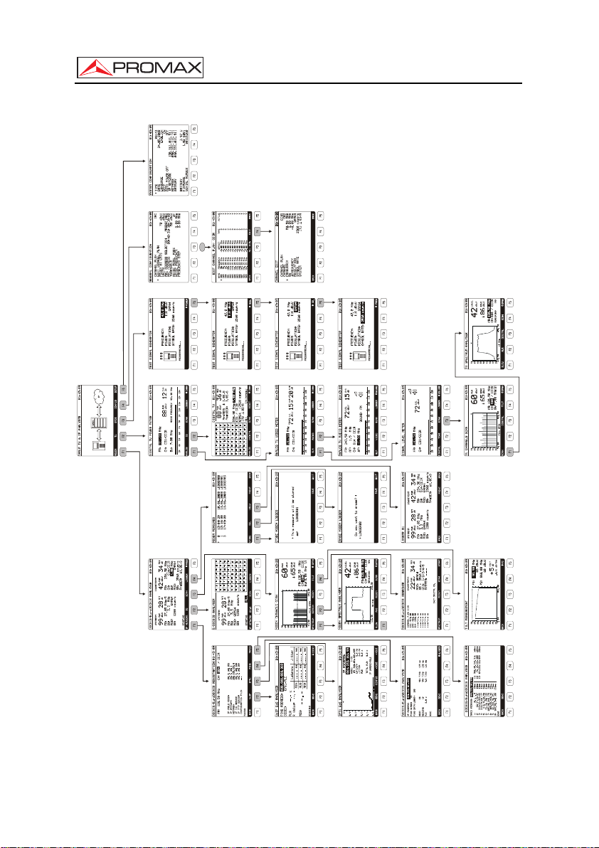
MENUS TREE
ARBRE DE MENUS
ARBOL DE MENÚS
SEL
PROMAX-27
Figure 4.- General view of menu tree. (See quick reference guide).
Page 14 07/2008
Page 19
USER’S MANUAL. PROMAX-27
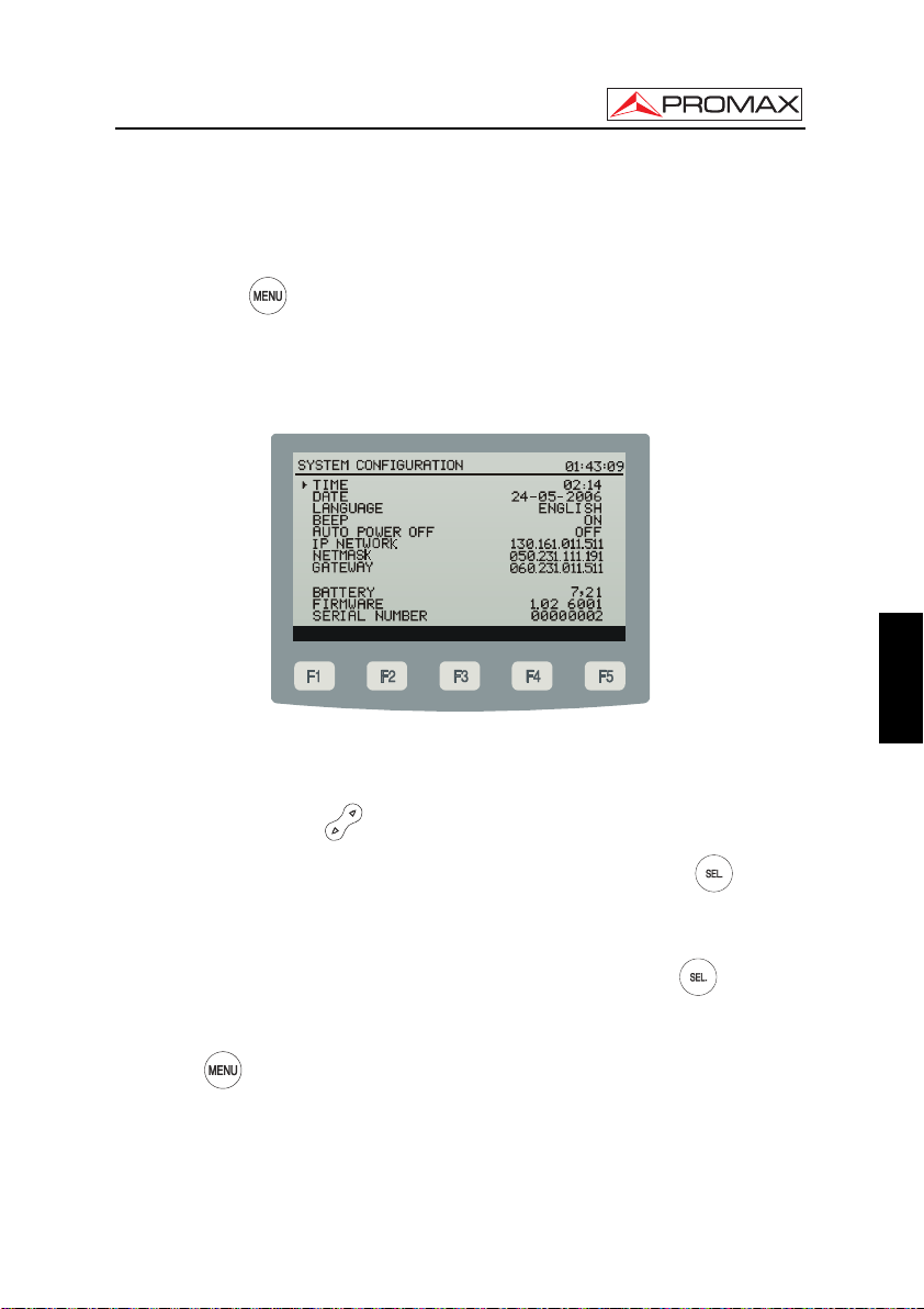
4.2.1 SETUP Mode
To access the SETUP mode for configuring system:
1.- Press key
[13].
2.- Press softkey SETUP [F5].
It will appear a screen with the configuration parameters of the system
(Figure 5.-).
Figure 5.- SETUP Screen.
To change the status or value of a parameter:
1.- Use the cursor keys
2.- Go to the parameter you want to modify and press the selection key [8].
[7] to scroll along the menu.
3.- The cursor will move next to the parameter value. Now you can change that value
using the cursor or the alphanumeric keypad (depending on the case).
English
4.- After you have made your changes, press again the selection key [8] to save
changes.
5.- To exit Configuration Mode and return to the main menu, press again the MENU
key
[13]
07/2008 Page 15
Page 20

USER’S MANUAL. PROMAX-27
Modifiable parameters are next:
a) HOUR
It indicates the current time. Enter hour and minutes by alphanumeric keypad. To
enter the symbol “:” between hours and minutes, you should use the key
which is in the alphanumeric keypad.
b) DATE
It indicates the current date in European notation (dd-mm-yy). Enter the day, month
and year by the alphanumeric keypad. To enter the hyphen symbol between
numbers, press key
that is in the alphanumeric keypad.
c) LANGUAGE
The language selected is the language usually used on the menus. Use the cursor
keys to scroll through available languages (English, Spanish, German and
Portuguese).
d) BIP
This parameter enables (ON) or disables (OFF) the acoustic indicator that beeps
when you press any key.
e) AUTO POWER OFF
This setting allows you to active (ON) or to disable (OFF) the auto power off
function. With this feature active, the instrument will automatically disconnect after
ten minutes without pressing any key.
f) IP NETWORK
It is the number used to identify the instrument within the network. You should use
the alphanumeric keypad to enter numbers that compose the IP address. You
should use the key
to write a point between numbers.
g) NETMASK
It is the number used to define the netmask. You should use the alphanumeric
keypad to enter numbers that compose the netmask address. You should use the
key
to write a point between numbers.
h) GATEWAY
It is the number used to define the gateway. You should use the alphanumeric
keypad to enter numbers that compose the gateway address. You should use the
key
to write a point between numbers.
Paragraphs f, g and h are needed to configure the Ethernet network connection.
At the bottom of the screen it appears the following information (no editable):
.,
Page 16 07/2008
Page 21
USER’S MANUAL. PROMAX-27
- BATTERY: Indicates the battery charge in voltage.
- FIRMWARE: Indicates control program version.
- SERIAL NUMBER: It is a unique identifier number for the instrument.
4.2.2 CONFIG Mode
To access the CONFIG mode for setting the general configuration of the system:
1.- Press key
[13]
2.- Press softkey CONFIG [F4].
It appears the screen with configuration parameters (Figure 6.-).
Figure 6.- CONFIG menu.
This menu allows you to set the parameters in order to the instrument can take
the TV digital and analog measurements, as well as the data analysis for upstream and
downstream.
To change a parameter:
1.- Use the cursor keys [7]
to scroll through the menu.
English
2.- Go to the parameter you want to modify and press the selection key [8].
3.- The cursor will move next to the parameter value. Now you can change that
value using the cursor or the alphanumeric keypad (depending on the case).
4.- After you have made your changes, press again the selection key [8] to
save changes.
07/2008 Page 17
Page 22

USER’S MANUAL. PROMAX-27
5.- To exit Configuration Mode and return to the main menu, press again the
MENU key
Modifiable parameters are next:
[13]
a) CHANNEL PLAN
It allows you to select the channel plan among the ten ones stored by default
in the instrument: CCIR, EIA, HRC, IRC, OIRL, UK, AUNAD, ST2L, AUST,
ONO.
b) EDIT CHANNEL PLAN
With this option you can edit the active channel plan. Through this option you
may get into the option EDIT (for details refer to section 4.2.2.1).
c) POWER AT CMTS
It defines the minimum level of signal that should receive the CMTS. It
accepts values between 20 and 120 dBµV. It is editable by curso or
alphanumeric keypad.
d) UNITS
It allows you to select measurement units to be used among dBmV, dBµV
and dBm.
e) MAC ADDRESS SELECTION
It validates the MAC code (Media Access Control address) which will be used
to identify you computer. This is a direction that identifies the instrument in a
unique way. There are two options: PREDEFINED, that uses the MAC
address defined by default and appears in the field MAC ADDRESS or
MANUAL that allows you to modify the MAC address, defining the address
we want.
f) MAC ADDRESS
It allows you to enter the MAC code that will be used to identify the
equipment.
g) THRESHOLD
It defines the minimum level of signal to detect. It is editable by the cursor
keys [7] and the alphanumeric keypad. At the SCAN function, the threshold is
represented in the chart by a dotted line. All measures below the threshold
value will not appear on screen. At the LOGGER function will not be
measured channels below the threshold value. At the SEARCH function will
not be searched channels below the threshold value.
h) NOISE MEASUREMENT MODE
It measures the noise level. It is only applicable to digital channels. There are
three ways to measure noise: FREC (Absolute), where noise level is
measured at the frequency noise defined at field NOISE FREQUENCY (see
paragraph i); ∆F (Relative), where is added the value defined in the field
NOISE FREQUENCY to the tuner frequency and BW/2, where is added the
value defined in NOISE FREQUENCY to the frequency of half the bandwidth
of the tuned channel.
Page 18 07/2008
Page 23

USER’S MANUAL. PROMAX-27
i) NOISE FREQUENCY
(Only for digital channels) Frequency at which is measured the level of noise
for digital channels.
j) STEP FREQUENCY
This option allows you to select the step frequency at the frequency tuning
4.2.2.1 EDIT CHANNEL PLAN
modes and at the GENERATOR mode.
To access the EDIT CHANNEL PLAN menu:
1.- Press key [13].
2.- Press softkey [F5] (SETUP)
3.- Use the cursor keys [7] to scroll along the menu.
4.- Go to the parameter “EDIT CHANNEL PLAN” and press the selection key [8].
It appears the screen with the configuration parameters (figure 7).
The attached figure (Figure 7.-) shows an example of a channel plan. At the top of
the screen appears the name of the selected plan channel (CCIR in the attached
figure). Along the screen are listed the channels belonging to the channel plan. The
maximum number of channels that a plan channel could have is 140.
From left to right are the following columns:
NAME: It identifies the channel name.
FREQUENCY: It identifies the frequency associated to the channel (MHz).
OFFSET: It shows the displacement of the tuning frequency in MHz.
TYPE: It indicates whether the channel is defined as analog (A) or
ACTIVE: It indicates whether the channel is active (Y) or not (N).
digital (D).
English
EDIT CHANNEL PLAN: CCIR 01:43:09
NAME FREQUENCY OFFSET TYP E ACTIVE
C02 50.25 MHz +0.00 MHz D Y
C03 55.25 MHz +0.00 MHz D Y
C04 62.25 MHz +0.00 MHz D Y
S01 105.25 MHz +0.00 MHz D Y
S02 112.25 MHz +0.00 MHz D Y
S03 119.25 MHz +0.00 MHz D Y
S04 126.25 MHz +0.00 MHz D Y
S05 133.25 MHz +0.00 MHz D Y
S06 140.25 MHz +0.00 MHz D Y
S07 147.25 MHz +0.00 MHz D Y
S08 154.25 MHz +0.00 MHz D Y
S09 161.25 MHz +0.00 MHz D Y
BACK ALL DIG. EDIT BACK
Figure 7.- Channel Plan Editor.
07/2008 Page 19
Page 24

USER’S MANUAL. PROMAX-27
At the bottom of the screen it appears the following options:
BACK [F1] and [F5]: To return to the previous general configuration screen
CONFIG.
ALL D. / ALL A [F3].: If you select this option you could change the type of
signal defined in all channels to digital or analogue, as
appropriate.
EDIT [F4]: When selecting this option, you will access to the
CHANNEL EDIT mode (Figure 8.-) to configure the
parameters of the analogical or digital channel.
Figure 8.- CHANNEL EDIT menu
Next we explain with details the menu of the CHANNEL EDIT.
Depending on whether is an analogue or digital channel, the parameters will be
different. Following is described everyone.
CHANNEL PLAN: Name of the channel plan where is the active channel. No
editable.
CHANNEL: Name of the channel. It allows you to navigate among
FREQUENCY: Is the frequency related to the channel. Not editable.
BW: Bandwidth. Not editable.
existing channels.
OFFSET
(only for analogue
channels): It may vary between 2.5 and +2.5 MHz.
Page 20 07/2008
Page 25

USER’S MANUAL. PROMAX-27
SYSTEM
(only for analogue
channels): System type and communication standard. It can be
selected among systems PAL / SECAM / NTSC and
standards B/G, D/K, L , I, M, N. AUDIO FREQUENCY
(only for analogue channels): The frequency that the
audio signal is transmitted. No editable.
MODULATION
(only for digital channels): You can select among QPSK, QAM16, QAM32, QAM64,
QAM128, QAM256 modulation.
SYMBOL RATE
(only for digital channels): This value may be between 1000 and 7000 sym/s.
SYSTEM
(only for digital channels): Depending on the modulation used you should choose
the proper annex among following ones: ITU J.83 / A, ITU
J.83 / B, ITU J.83 / C.
In order to modify the rest of features of the channel plan, you will need the
RM-027 software.
To return to the previous menu (EDIT CHANNEL PLAN) press key BACK [F1] or
[F5]
To exit the menu EDIT CHANNEL PLAN and return to the previous screen
(CONFIG) press key BACK [F1] or [F5].
4.2.3 MODEM Mode
To access the MODEM mode in order to measure downstream, upstream and
services over IP :
English
1.- Press key
2.- Press softkey MODEM [F1].
[13].
3.- It appears the initial screen in MODEM mode (Figure 9.-).
07/2008 Page 21
Page 26

USER’S MANUAL. PROMAX-27
DOCSIS/EuroDO CSIS ANALYSER
UPSTREAM:
PWR
dBuV
FR: 27.05 MH z/5
BW: 3.3 MHz
MOD: QAM64
SR: 1280 ksym/s
STARTING
IP NETWORK IQ SPECTRUM LOGGER FREQ
2899
Figure 9.- Initial MODEM Screen.
DOWNSTREAM:
ATT
dB
FR: 254.50 MHz
CH: S14/C CIR
BW: MH z
MOD: QAM64
SR: 2560 ksym/s
PreBER: 1.0E-8
PWR
dBuV
01:43:09
3442
7.00
MER
dB
To change between displaying downstream data or the constellation diagram
press IQ / DOWN [F2].
To enable or disable the constellation diagram press the selection key [8]
The measurement of power in digital channels is done by a method of integration,
with a bandwidth defined by the channel or the user.
The uplink, (UPSTREAM) shows the channel that the equipment uses in the
communication with the CMTS (Cable Modem Termination System).
The screen shows measurements for both upstream and downstream, where:
Downstream:
- PWR: Channel power.
- MER: Modulation Error Ratio.
- PreBER: Digital signal Error Ratio.
- FR: Frequency.
- CH: Channel and active channel plan.
- MOD: Modulation.
- SR: Symbol Rate.
Upstream:
- PWR: Uplink level power.
- ATT: Attenuation until CMTS.
- FR: Frequency.
Page 22 07/2008
Page 27

USER’S MANUAL. PROMAX-27
- BW: Bandwidth.
- MOD: Modulation.
- SR: Symbol Rate.
At the bottom of the screen are displayed the following options:
IP NETWORK [F1]: It reports about data network (refer to section 4.2.4).
DOWN / IQ [F2]: Pressing this key you can switch between downstream
data report and downstream constellation (refer to
section 4.2.3.1).
SPECTRUM / SCAN [F3]: Goes to SPECTRUM function (refer to section 4.2.3.4) /
SCAN function (refer to section 4.2.3.3).
REGISTER [F4]: Through this function you can store measurements in
the memory of the instrument for later viewing, printing
or transfer to a PC (refer to section 4.2.3.5).
FREQ / BW / CHAN [F5]: Pressing this key you can navigate among editable
parameters. To edit a value use the Cursor keys or the
alphanumeric keypad, as appropriate. In this case you
can edit: FREQ, is the frequency of the tuned channel;
BW, is the bandwidth; CHANNEL, is the name of the
tuned channel. By this way you can change the tuned
channel and measure other signals.
NOTE:
Access to the function SCAN / SPECTRUM switches depending on the type of
tuning you are doing.
In case you are tuning a signal using frequency, it will be displayed the
SPECTRUM function first.
In case you are tuning a signal using the predefined channels from the channel
plan, it will be displayed the SCAN function first.
4.2.3.1 CONSTELLATION DIAGRAM (IQ)
To access the IQ (Constellation Diagram) function;
English
1.- Press key
2.- Press softkey MODEM [F1].
[13].
3.- Press softkey IQ [F2].
07/2008 Page 23
Page 28

USER’S MANUAL. PROMAX-27
It is the graphic representation of the Constellation Diagram (Figure 10.-) for DVBQAM digital signal. For details see Appendix B “Principle of QAM Modulation. The
constellation Diagram”.
E/DOCSIS ANAL YSER
UPSTREAM
PWR
dBuV
FR: 27.05 MH z/01
BW: 3.3 MH z
MOD: QAM64
SR: 1280 ksym/s
ATT
dB
2899
STARTING
IP NETWORK DOWN SPECTRUM LOGGER
Figure 10.- Constellation Diagram.
ALL
Measurements displayed on the screen:
PWR: Uplink level power.
ATT: Attenuation until CMTS.
FR: Carrier frequency and UCI.
BW: Signal bandwidth.
MOD: Modulation.
SR: Symbol rate.
At the bottom of the screen, next to the lower left corner of the diagram, it is
indicated what quadrant is represented on screen.
Using the Cursor keys [7] you can change quadrant of the constellation:
The initial option ALL represents the whole diagram.
Options Q1, Q2, Q3, Q4 show each one of the four quadrants.
Options ZQ1, ZQ2, ZQ3 and ZQ4 show a zoom in of each quadrant.
Pressing the selection key [8] it switches between viewing and hiding the
constellation diagram.
Page 24 07/2008
Page 29

USER’S MANUAL. PROMAX-27
At the bottom of the screen is shown the following options:
IP NETWORK [F1]: Registers into the network it reports about data network
(refer to section 4.2.4).
DOWN / IQ [F2]: It switches between downstream data viewing (refer to
section 4.2.3.1) and downstream constellation viewing.
SPECTRUM / SCAN [F3]: It shows the SPECTRUM screen (refer to section
4.2.3.4) / SCAN screen (refer to section 4.2.3.3).
LOGGER [F4]: Through this function you can store measurements in
the memory of the instrument for later viewing, printing
or transfer to a PC (refer to section 4.2.3.5).
NOTE:
Access to the function SCAN / SPECTRUM switches depending on the type of
tuning you are doing.
In case you are tuning a signal using frequency, it will be displayed the
SPECTRUM function first.
In case you are tuning a signal using the predefined channels from the channel
plan, it will be displayed the SCAN function first.
4.2.3.2 SEARCH function
To access the SEARCH function:
English
1.- Press key
2.- Press softkey MODEM [F1].
3.- Press softkey SPECTRUM / SCAN [F3].
4.- Press softkey SCAN [F4] (if coming from SPECTRUM screen).
[13].
5.- Press softkey SEARCH [F2].
The SEARCH function identifies potential channels where you can make a
ranging (determination of scope) with a number. The number of these identifiers, as well
as its order it will determinate the time that may takes in adjust the emission power
(ranging).
07/2008 Page 25
Page 30

USER’S MANUAL. PROMAX-27
DOCSIS/EuroDO CSIS SEARCHER 01:43:09
CHANNEL PLAN CCIR
C33 /570.00
C73 /363.00
S14 /254.50
----/---.--
----/---.--
----/---.--
----/---.--
----/---.--
SPECTRUM MODEM SCAN START
DOWNSTREAM:
MOD: QAM64
SR : 2560 ksym/s
UCI: 1/2/3/4/5
SYSTEM: ----
ONLY DIGITAL CH.
PWR
dBuV
MER
dB
3422
Figure 11.- SEARCH function.
Measurements shown on the screen (Figure 11.-) are:
PWR: Input power.
MER: Imodulation Error Ratio.
MOD: Modulation used to codify the signal.
SR: Symbol rate.
UCI: Upstream Channel Identification.
SYSTEM: It is the system used to send the signal.
At the bottom of the screen are shown the following options:
SPECTRUM [F1]: Returns to SPECTRUM screen (refer to section
4.2.3.4).
MODEM [F3]: Returns to the MODEM screen (refer to section 4.2.3).
SCAN [F4]: Returns to the SCAN screen (refer to section 4.2.3.3).
START [F5]: Starts searching for channels.
NOTE:
Access to the function SCAN / SPECTRUM switches depending on the type of
tuning you are doing.
In case you are tuning a signal using frequency, it will be displayed the
SPECTRUM function first.
In case you are tuning a signal using the predefined channels from the channel
plan, it will be displayed the SCAN function first.
Page 26 07/2008
Page 31

USER’S MANUAL. PROMAX-27
4.2.3.3 SCAN function
To access the SCAN function
1.- Press key
[13].
2.- Press softkey MODEM [F1].
3.- Press softkey SPECTRUM / SCAN [F3].
4.- Press softkey SCAN [F4] (if coming from SPECTRUM screen).
The SCAN function shows numerically the level of the channel where the cursor,
which is at the top of the screen, is pointing (Figure 12.-).
Figure 12.- SCAN function.
Measurements displayed on the screen:
PWR: It indicates the signal power.
ΣPWR: It indicates the summation of power signals along the
FR: Carrier intermediate frequency.
CH: Shows the channel and active plan channel.
BW: Bandwidth of the signal.
frequency band (from 5 to 1000 MHz).
: Indicates whether the selected channel is digital or analogue.
The dotted line at the graph indicates the threshold level, below which will not
show any power signal.
English
07/2008 Page 27
Page 32

USER’S MANUAL. PROMAX-27
At the bottom of the screen are shown the following options:
SPECTRUM [F1]: It leads to the SPECTRUM screen (refer to section
4.2.3.4).
SEARCH [F2]: It makes an exploration of all channels DOCSIS /
EuroDOCSIS presents at the frequency band of the
active channel plan (refer to section 4.2.3.2).
MODEM [F3]: Returns to the main screen MODEM (refer to section
4.2.3).
TILT [F4]: Goes to TILT test (refer to section 4.2.3.6).
LEVEL / CHAN /
SPAN [F5]: Pressing this key you can navigate among editable
parameters. To change them, use the Cursor keys or
the alphanumeric keypad as appropriate. It can be
edited the LEVEL, to change the margin of the power
on the vertical axis of the graph, CHANNEL, to change
the channel we are analysing; SPAN, to change the
frequency range shown on the horizontal axis of the
graph. Possible values are 10, 30, 100, 300 MHz and
NOTE:
Access to the function SCAN / SPECTRUM switches depending on the type of
tuning you are doing.
MAX SPAN.
In case you are tuning a signal using frequency, it will be displayed the
SPECTRUM function first.
In case you are tuning a signal using the predefined channels from the channel
plan, it will be displayed the SCAN function first.
4.2.3.4 SPECTRUM function
To access the SPECTRUM function:
1.- Press key
2.- Press softkey MODEM [F1].
3.- Press softkey SPECTRUM / SCAN [F3].
4.- Press softkey SPECTRUM [F1] (if coming from SPECTRUM screen).
[13].
The SPECTRUM function performs a spectrum graph at the highest resolution. By
this way, interferences can be detected, both in active channels and adjacent ones
(Figure 13.-).
Page 28 07/2008
Page 33

USER’S MANUAL. PROMAX-27
Figure 13.- SPECTRUM function in MODEM mode.
At the SPECTRUM function, the meter represents the spectrum of frequencies
where the marker is. It provides an agile analysis of the whole band.
Data on the screen are:
PWR: Power received from signal.
ΣPWR: It indicates the summation of power signals along the
FR: Channel frequency.
CH: Selected channel and active plan channel.
frequency band (from 5 to 1000 MHz).
MEASURING: It is the measurement it is using.
At the bottom of the screen you will see next options:
SLOW / FAST [F1]: It can be changed the scanning speed.
AVG / MAX / PEAK [F2]: It can be changed the measurement mode. The current
mode appears below the selected channel. In the
AVERAGE option it makes an average of values; in the
MAX HOLD option, it keeps the maximum values
measured due to impulsive signals, remaining on the
screen with dotted lines; PEAK option uses as
reference the peak values.
MODEM [F3]: It leads to the MODEM screen (refer to section 4.2.3).
SCAN [F4]: It goes to the SCAN screen (refer to section 4.2.3.3).
English
07/2008 Page 29
Page 34

USER’S MANUAL. PROMAX-27
LEVEL / CHAN /
FREQ / SPAN [F5]: Pressing this key you can navigate among editable
parameters. To change them, use the Cursor keys or
the alphanumeric keypad as appropriate. It can be
edited the LEVEL, to change the margin of the power
on the vertical axis of the graph, CHANNEL, to change
the channel we are analysing; FREQUENCY, to change
the frequency; SPAN, to change the frequency range
shown on the horizontal axis of the graph. Possible
values are 1/5/15/30/50/100 MHz.
NOTE:
Access to the function SCAN / SPECTRUM switches depending on the type of
tuning you are doing.
In case you are tuning a signal using frequency, it will be displayed the
SPECTRUM function first.
In case you are tuning a signal using the predefined channels from the channel
plan, it will be displayed the SCAN function first.
4.2.3.5 LOGGER function.
To access the LOGGER function:
1.- Press key
2.- Press key MODEM [F1].
[13].
3.- Press key LOGGER [F4].
Using the LOGGER function in MODEM mode you can obtain a record of the
measurements taken for both Upstream and Downstream.
Data stored are next:
Downstream:
- Power
- MER and BER
- Channel frequency.
- Symbol rate.
Page 30 07/2008
Page 35

USER’S MANUAL. PROMAX-27
Upstream:
- Power checking
- Attenuation until CMTS
- Bandwidth and Frequency
- Symbol rate
The PROMAX-27 can store in its memory up to 30 acquisitions or loggers in
MODEM mode. These measurements are stored for later viewing, printing or transfer to
a PC.
On the left side of the screen (Figure 14.-), you can see the recording number,
followed by time and date it was saved and the name given. The instrument
automatically assigns a sequential name to the file or reuses a name of a removed file.
MODEM MEASURES 01:43:09
0 13:04:29 10-06-2008 LOG GER00
1 13:16:00 11-06-2008 LOG GER01
3 17:45:00 11-06-2008 LOG GER03
STORE DEL VIEW PRINT BACK
Figure 14.- List of stored loggers.
If there are not files stored, it will be shown the message “EMPTY LOGGER”.
At the bottom of the screen you will see next options:
STORE [F1]: Measurements corresponding to channels of the
channel plan selected are stored in a logger.
DEL [F2]: It deletes the logger that the cursor is pointing at.
System requires confirmation. To confirm delete press
F4. To cancel press F5.
VIEW [F3]: It allows you to access the data stored in the selected
logger (Figure 15.-)
07/2008 Page 31
English
Page 36

USER’S MANUAL. PROMAX-27
LOGGER 01
UPSTREAM
PWR
dBuV
FR: 27.05 MH z
BW: 3.3 MHz
MOD: QAM64
SR: 1280 ksym/s
BACK PRINT BACK
2899
Figure 15.- Logger Viewing in MODEM mode.
DOWNSTREAM
ATT
dB
FR: 254.50 MHz
CH: S14/CCI R
MOD: QAM64
SR: 2560 ks ym/s
PreBER: 1.0E-8
PWR
dBuV
01:43:09
MER
dB
3442
Pressing [F1] or [F5] you will return to the previous screen (LOGGER).
Pressing [F4] displayed logger data will be print.
PRINT [F4]: It prints the selected log (Figure 16.-) (refer to section
4.3).
************************
* PROMAX-27 *
************************
00:01:38 01-01-2006
************************
************************
************************
************************
UPSTREAM
PWR: 91 dBuV
ATT: 21 dB
FR: 27.05 MHz
BW: 3.2 MHz
SR: 2560 ksym/s
DOWNSTREAM
PWR: 82 dBuV
MER: 32 dB
FR: 303.00 MHz
CH: C37 / IRC
SR: 5057 ksym/s
BER: <1.0E-8
Figure 16.- Print example.
BACK [F5]: It returns to the previous screen MODEM.
Page 32 07/2008
Page 37

USER’S MANUAL. PROMAX-27
T
4.2.3.6 TILT function
To access the TILT function:
1.- Press key
2.- Press softkey MODEM [F1].
3.- Press softkey SPECTRUM / SCAN [F3].
4.- Press softkey SCAN [F3] (if coming from SPECTRUM screen).
[13].
5.- Press softkey TILT [F4].
The TILT test is a utility to equalize the line. Typically, CATV networks transmit
two pilot signals at the beginning and at the end of the band. These two pilots are the
ones that can be tuned simultaneously on the screen. By this way you can evaluate the
losses slope and therefore readjust equalizers of amplifiers in order to compensate
these losses and ensure a flat response across the band.
TILT MEASUREM ENT 01:43:09
70
65
60
55
50
45
40
35
30
5.00 862. 00
BACK P2
Figure 17.- TILT Screen
P1: MHz
97.90
65 dBuV
P2: 860.00 MHz
60 dBuV
ILT
dB
+5
-0.01 dB/MH z
At the bottom of the screen (Figure 17.-) you will see next options:
BACK [F1]: To return to the previous menu.
PILOT 1 / PILOT 2 [F2]: Pressing this key you can navigate among editable
parameters. To change them, use the Cursor keys or
the alphanumeric keypad as appropriate. PILOT 1, is
used to define the first reference frequency, PILOT 2, is
used to define the second reference frequency. If using
Cursor keys to define the frequency, it will be by steps
selected in STEP FREQUENCY (see paragraph 4.2.2).
If using alphanumeric keypad, press SELECT to save
values and finish.
Test Equipment Depot - 800.517.8431 - 99 Washington Street Melrose, MA 02176
07/2008 Page 33
FAX 781.665.0780 - TestEquipmentDepot.com
English
Page 38

USER’S MANUAL. PROMAX-27
4.2.4 REGISTERED Mode — IP NETWORK Functions
In order to use the REGISTERED mode functions is necessary to register the
instrument in the network, configuring the information needed to identify it, such as IP,
Netmask and Gateway (refer to section 4.2.1). If you are not registered in the network
you will be able to access these functions but they will be disabled.
To access the REGISTERED mode, in order to analyse network services.
1.- Press key
2.- Press softkey MODEM [F1].
3.- Press softkey IP NETWORK [F1].
[13].
4.- The instrument starts the registration process in the CMTS of the NETWORK.
On the display it will appear the word "TUNING" during the process. You must
wait a few minutes until it is registered. If registration process is right, it will
display the word "DONE" on the screen. Failure in registration process will be
displayed as an "ERROR IN REGISTRATION".
It is displayed the REGISTERED mode screen. At the bottom menu it is shown
each one of functions that you may use (Figure 18.-).
DOCSIS/EuroDO CSIS REGISTRATION 01:43:09
FR: 128.50 MHz
IP CABLE MODEM:
IP GATEWA Y:
NETMASK:
IP TOD SE RVER:
IP TFTP SERVER:
CONFIGURA TION FILE :
TUNING
BACK VoIP IPTV PING TRACE
Figure 18.- Registered mode Screen.
CH: / CCIRS04
192.9.100 .252
192.9.100 .1
255.255.2 55.0
192.9.100 .248
192.9.100 .204
---
At the bottom of the screen it will appear next options:
BACK [F1]: Back to the previous screen MODEM.
VoIP [F2]: It checks the VoIP service (refer to section 4.2.4.1).
IPTV [F3]: It checks the TV over IP service (refer to section
4.2.4.2).
Page 34 07/2008
Page 39

USER’S MANUAL. PROMAX-27
PING [F4]: It checks the packet transmission over the cable (refer
to section 4.2.4.3).
TRACE [F5]: It shows the route taken by packets across an IP
network, from the instrument to the host (refer to
section 4.2.4.4).
Next we are going to explain each one of functions you can use in register mode:
VoIP, IPTV, PING and TRACEROUTE.
4.2.4.1 VoIP
Service Description
To implement the basic telephony service in CATV networks is necessary to
consider the profile of a demanding customer used to the quality of traditional telephone
networks. To meet those expectations must be maintained almost the quality of the
traditional service.
The protocol DOCSIS / EuroDOCSIS uses the concept of service flows for traffic
transmitted between cable modem and CMTS. A service flow is a one-way packets flow
that provide a specific service quality. Traffic is classified in a service flow, and each
service flow has its own set of parameters, named QoS.
QoS (Quality of Service) are technologies that ensure the transfer of certain
amount of data at a time, ensuring a good quality of service.
There are four types of QoS defined, depending on the type of data to transmit:
UGS (Unsolicited Grant Service), rtPS (real time Polling Service), nrtPS (non real time
Polling Service) and BE (Best Effort).
In the case of VoIP, voice over IP, the type UGS is the most suitable, because it
is designed for applications that generate fixed-size packets on a periodic basis. In this
type, CMTS provides a fixed-size grant to a service flow at fixed intervals without
additional polling or interaction.
The PROMAX-27 allows the user to establish a service flow to verify the quality of
service based on type UGS type. Flow services are used to verify the network between
the test point and the CMTS. It analyses parameters that can affect the quality of
communication, among them latency, jitter, lost packets, MOS and R-value.
In short, the VoIP function of the PROMAX-27, performs an exhaustive analysis
of the network based on parameters set by UGS, which will ensure the best quality
service.
English
07/2008 Page 35
Page 40

To access the VoIP function:
USER’S MANUAL. PROMAX-27
1.- Press key
2.- Press softkey MODEM [F1].
[13].
3.- Press softkey RED IP [F1].
4.- The instrument starts the registration process in the CMTS of the NETWORK.
On the display it will appear the word "TUNING" during the process. You must
wait a few minutes until it is registered. If registration process is right, it will
display the word "DONE" on the screen. Failure in registration process will be
displayed as an "ERROR IN REGISTRATION".
5.- Pres softkey VoIP [F2].
VoIP QoS ANAL YSER 01:43:09
PING ADDRESS:
CODEC: G711+PLC
PLR 5.0 %
R Value:
MOS:
DONE
BACK SEND CONFIG CODEC
064.233.161.099
Latency Jitter
77.4
MIN 60.0 ms 0.1 ms
3.92
AVG 60.1 ms 0.2 ms
MAX 62.5 ms 2.4 ms
Figure 19.- VoIP Screen.
On the screen (Figure 19.-) are displayed next data:
IP ADDRESS: Address where PING is send.
PLR (Packet
Loss Rate): Is the percentage of lost packets over total sent packets.
CODEC: Type of encoding used for signal transmission.
R-VALUE: It shows a number, or score, that is used to quantitatively
express the subjective quality of speech in communications
systems. Can range from 1 (worst) to 100 (best).
MOS (Mean
Opinion Score): It is a numerical indication of the perceived quality of received
media after compression and/or transmission. The MOS is
expressed as a single number in the range 1 to 5, where 1 is
lowest perceived quality, and 5 is the highest perceived
quality.
Page 36 07/2008
Page 41

USER’S MANUAL. PROMAX-27
LATENCY: It is the time delay, between initial input and output due to
transport or processing. It shows the minimum, average and
maximum measurement.
JITTER: It is an unwanted variation of one or more characteristics of a
periodic signal. Jitter may be seen in characteristics such as
the interval between successive pulses, or the amplitude,
frequency, or phase of successive cycles. Are shown the
minimum, average and maximum measurements.
If the device is not properly registered in the network, at the bottom of the screen
it will display the warning message "Register Error".
At the bottom menu it is shown each one of functions that you may use.
BACK [F1]: To return to the previous screen (REGISTERED).
SEND [F2]: To send the ping.
CONFIG [F4]: You will access to VoIP settings. Among them there
are: Ping data length, ping number, unsolicited grant
size, grants per interval, nominal grant interval,
tolerated grand jitter. Use the cursor to move among
parameters and the selection key [8] to enter and save
them.
CODEC / ADDRESS [F5]: Pressing this key you can navigate among editable
parameters. To change them, use the Cursor keys or
the alphanumeric keypad as appropriate. You can
change the PING ADDRESS or the CODEC. When
selecting IP address, if you use the cursor keys you will
access to last IP entered by the user.
4.2.4.2 IPTV
Description of Service
IPTV (Internet Protocol Television) is a system where a digital TV service is
distributed on a network infrastructure using the IP protocol.
The protocol DOCSIS / EuroDOCSIS uses the concept of service flows for traffic
transmitted between cable modem and CMTS. A service flow is a one-way packets flow
that provide a specific service quality. Traffic is classified in a service flow, and each
service flow has its own set of parameters, named QoS.
QoS (Quality of Service) are technologies that ensure the transfer of certain
amount of data at a time, ensuring a good quality of service.
English
07/2008 Page 37
Page 42

USER’S MANUAL. PROMAX-27
0
In the case of IPTV, the type rtPS (Real-Time Polling Service) is the most
suitable. rtPS is one of the four QoS defined in DOCSIS / EuroDOCSIS, and is
designed to support service flows with real-time traffic that generates variable-size data
packets on a periodic basis and has inflexible latency and throughput requirements, as
in the case of video MPEG. This service requires more demand to CMTS than the UGS
type, but supports variable grant sizes for an optimum efficiency in data transport.
The PROMAX-27 allows the user to establish a service flow to verify the quality of
service based on type rtPS. Flow services are used to verify the network between the
test point and the CMTS. It analyses parameters than can affect quality signal, like
latency, jitter, lost packets and trace route, which trace the route of sent packets on a
graph. This will be useful to detect possible bottlenecks.
In short, the IPTV function of the PROMAX-27, performs an exhaustive analysis
of the network based on parameters set by rtPS, which will ensure the best quality
service. The deep knowledge about network conditions will guide you during installation
and will help you solving problems that may arise.
To access to IPTV function:
1.- Press key
2.- Press softkey MODEM [F1].
3.- Press softkey IP NETWORK [F1].
[13].
4.- The instrument starts the registration process in the CMTS of the NETWORK.
On the display it will appear the word "TUNING" during the process. You must
wait a few minutes until it is registered. If registration process is right, it will
display the word "DONE" on the screen. Failure in registration process will be
displayed as a "ERROR IN REGISTRATION".
5.- Press softkey IPTV [F3].
IPTV QoS ANAL YSER
s
0.4
0.3
0.2
0.1
0.0
BACK SEND CONFIG -NODE +NODE
Figure 20.- IPTV screen.
IP ADDRESS:
064.233.161.99
NODE: 1/15
IP: 010.001 .001.005
LATENCY: 5.0 ms
JITTER: 2.0 m s
PLR 0.0 %
TOTAL PLR: 0.0 %
IP UNREAC HABLE
1:43:09
Page 38 07/2008
Page 43

USER’S MANUAL. PROMAX-27
On the display (Figure 20.-) are shown different measurements:
PING
ADDRESS: Address where PING is send. When selecting IP address, if
you use the cursor keys you will access to last IPs entered by
NODE: Indicates the node where you are connected.
IP: Indicates the IP where you are sending the PING.
the user.
LATENCY: It is the time delay, between initial input and output due to
transport or processing. It shows the minimum, average and
maximum measurement.
JITTER: It is an unwanted variation of one or more characteristics of a
periodic signal. Jitter may be seen in characteristics such as
the interval between successive pulses, or the amplitude,
frequency, or phase of successive cycles.
PLR (Packet
Loss Rate): Is the percentage of lost packets over total sent packets.
TOTAL PLR: It shows the total number of lost packets.
If the device is not properly registered in the network, at the bottom of the screen
it will display the warning message "Register Error".
At the bottom of the screen is shown the following options:
BACK [F1]: To return to the previous screen (REGISTERED
mode).
SEND [F2]: To send the testing ping.
CONFIG [F3]: You will access to IPTV settings (Nominal Polling
Interval).
+NODE [F4]: Moves the cursor to the right, going to the next node.
—NODE [F5]: Moves the cursor to the left, going to the previous node.
4.2.4.3 PING
Description of Service
The protocol DOCSIS / EuroDOCSIS uses the concept of service flows for traffic
transmitted between cable modem and CMTS. A service flow is a one-way packets flow
that provides a specific service quality. Traffic is classified in a service flow, and each
service flow has its own set of parameters, named QoS.
English
07/2008 Page 39
Page 44

USER’S MANUAL. PROMAX-27
QoS (Quality of Service) are technologies that ensure the transfer of certain
amount of data at a time, ensuring a good quality of service.
In the case of standard Internet traffic, such as browsing websites, emails or
instant messaging, the quality of service defined as BE (Best Effort) is the most
appropriate. BE is one of the four services QoS defined in DOCSIS / EuroDOCSIS, and
is designed to work on a "first come, first served" basis.
To perform the PING test, a PING (Packet Internet Grouper) is sent. It is about
transmitting data packets point to point between PROMAX-27 serving as cable modem
and another remote point access to the network that answer to the transmission. These
PING are a set data packets with a request and response echo. This way it can be
checked the status of the connection with the test point to verify.
From the obtained data it is displayed a BE report, the PLR and latency. The
results shown indicate what problems must be identified and resolved and those ones
that may be caused by problems at headers or IP.
In short, the PING function of the PROMAX-27, performs an exhaustive analysis
of the network based on parameters set by BE, which will ensure the best quality
service. The deep knowledge about network conditions will guide you during installation
and will help you solving problems that may arise.
To access the PING function:
1.- Press key [13].
2.- Press softkey MODEM [F1].
3.- Press softkey IP NETWORK [F1].
4.- The instrument starts the registration process in the CMTS of the NETWORK.
On the display it will appear the word "TUNING" during the process. You must
wait a few minutes until it is registered. If registration process is right, it will
display the word "DONE" on the screen. Failure in registration process will be
displayed as an "ERROR IN REGISTRATION".
5.- Press softkey PING [F4].
DOCSIS/EuroDO CSIS ANALYSER 01:43:09
IP ADDRESS:
PING NUMBER 20
PING DATA LENGTH 100
SEND 20
RECEIVE 19
PLR 5.0 %
DONE
BACK SEND NUMBER
064.233.161.099
MIN TIME: 125 ms
MAX TIME: 150 ms
AVG TIME: 126 ms
Figure 21.- PING report.
Page 40 07/2008
Page 45

USER’S MANUAL. PROMAX-27
Data shown on the screen (Figure 21.-) are:
PING
ADDRESS: It indicates the remote address of the device or the access
PING NUMBER: It indicates the number of PING attempts.
point to verify. This is an editable field.
PING DATA
LENGHT: It indicates the length of the PING sent in bytes.
SEND: It indicates the number of sent PING packets.
RECEIVE: It indicates the number of PING packets received.
PLR (Packet
Lost Rate): Is the percentage of lost packets over total sent packets.
MIN TIME: It indicates the minimum time that a PING has been sent and
received back.
MAX TIME: It indicates the maximum time that a PING has been sent and
received back.
AVG TIME: It indicates the average time in which PINGs were sent and
received back.
If the device is not properly registered in the network, at the bottom of the screen
it will display the warning message "Register Error".
At the bottom of the screen appears following options:
BACK [F1]: Return to the previous screen REGISTER.
SEND [F2]: Sends the PING.
NUMBER /
LENGTH / IP [F5]: Pressing this key you can navigate among editable
parameters. To change them, use the Cursor keys or
the alphanumeric keypad as appropriate. It can be
edited the PING number, its LENGHT or its NUMBER.
When selecting IP address, if you use the cursor keys
you will access to last IPs entered by the user.
4.2.4.4 TRACEROUTE
Description of Service
Traceroute is a service that shows you the route over the network between two
systems, listing all the intermediate routers a connection must pass through to get to its
destination.
English
07/2008 Page 41
Page 46

USER’S MANUAL. PROMAX-27
This function can help you determine why a connection to a given server might be
poor, and can offer help you figure out where exactly the problem is.
It also shows you how systems are connected to each other, letting you see how
your ISP connects to the Internet as well as how the target system is connected.
To access the TRACEROUTE function:
1.- Press key
2.- Press softkey MODEM [F1].
3.- Press softkey IP NETWORK [F1].
[13].
4.- The instrument starts the registration process in the CMTS of the NETWORK.
On the display it will appear the word "TUNING" during the process. You must
wait a few minutes until it is registered. If registration process is right, it will
display the word "DONE" on the screen. Failure in registration process will be
displayed as an "ERROR IN REGISTRATION".
5.- Press softkey TRACE [F5].
DOCSIS/EuroDOC SIS ANALYSER 01:43: 09
TRACE ADDRESS: 064.233.1 61.099
1: 10.1.1.5 10ms
2: 62.97.99.57 10ms
3: 213.27.253.85 13ms
4: 212.74.69.177 13ms
5: 212.74.65.58 36ms
6: 72.14.198.133 41ms
7: 209.85.249.178 75ms
8: 209.85.248.44 55ms
9: 66.249.94.251 75ms
10: 209.85.248.180 136ms
DONE
BACK SEND
Figure 22.- TRACEROUTE Screen.
11: 209.85.248.216 140ms
12: 72.14.236.200 128ms
13: 64.233.161.099 150ms
Each line on the screen (Figure 22.-) shows each system or router in the path
between the instrument and the target system. Each line shows the system’s IP address
and time in millisecond that is how long it took a packet to get from the instrument to
that system and back again.
If the device is not properly registered in the network, at the bottom of the screen
it will display the warning message "Register Error".
At the bottom of the screen appears following options:
BACK [F1]: Return to the previous screen REGISTER.
Page 42 07/2008
Page 47

USER’S MANUAL. PROMAX-27
SEND [F2]: Sends the PING.
4.2.5 TV Mode
To access the TV mode for CATV measurement:
1.- Press key
[13].
2.- Press softkey TV [F2].
The TV function includes three different operation modes: Analogue, Digital and
SLM (Signal Level Meter). Next we explain measurements of each mode.
Analog TV Video Meter:
- Video carrier level.
- Carrier / Noise Ratio (C/N).
- Video / Audio Ratio (V/A).
Digital TV Power Meter:
- Channels Power by Integration.
- Carrier / Noise Ratio (C/N).
- Bit Error Rate (BER).
- Modulation Error Ratio (MER).
- Constellation Diagram.
Signal Level Meter (SLM):
- Select the Tone, AM, FM and volume regulation.
- Power level Channel.
Once in TV mode, to change the measurement mode you should press the
softkey [F1].
MNS / DIGITAL
/ ANALOGUE [F1]: Changes among the three TV measurement modes.
At the top of the screen you can read in which mode you are.
Next we are going to explain each one.
English
07/2008 Page 43
Page 48

USER’S MANUAL. PROMAX-27
4.2.5.1 TV DIGITAL mode
To access this measurement mode from TV mode, press [F1] until you see at the
top of the screen “DIGITAL TV POWER METER” (Figure 23.-).
DIGITAL TV POWER METER 01:43:09
FR: MHz
CH: C31/CCIR
BW: 7.00 MHz
34 44 54 64 748494 104 114 124 134
ANALOG IQ SPECTRUM LOGGER CHAN
Figure 23.- Digital TV measurement screen
PWR
dBuV
NOISE FRE QUENCY: 4 51.00 MHz
C/N
dB
1288
Measures on the screen are:
PWR: Power received from the signal.
C/N: Carrier / Noise Ratio.
NOISE
FREQUENCY: Noise frequency.
FR: Channel tuned frequency.
CA: Channel and plan channel.
BW: Bandwidth.
At the bottom of the screen you will see next options:
MNS / DIGITAL /
ANALOG [F1]: Changes among the three TV measurement modes.
IQ [F2]: It shows a Constellation Diagram for the digital signal in
the whole range of measurement (refer to section
4.2.5.1.1) (for details see appendix B ’Principle of QAM
Modulation. The Constellation Diagram').
SPECTRUM / SCAN [F3]: It leads to SPECTRUM mode (refer to section 4.2.5.4.2)
/ SCAN mode (refer to section 4.2.5.4.1).
LOGGER [F4]: Through this function you can store measurements in
the memory of the instrument for later viewing, printing
or transfer to a PC (refer to section 4.2.5.4.3).
Page 44 07/2008
Page 49

USER’S MANUAL. PROMAX-27
0
CHAN / BW / FREQ [F5]: Pressing this key you can navigate among editable
parameters. To change them, use the Cursor keys or
the alphanumeric keypad as appropriate. FREQ for
changing the frequency value of the tuned channel, BW
for changing the bandwidth and CHANNEL for
changing the channel of the channel plan.
If channel you are analysing is defined as analogue, it will appear a warning
message on the screen. The message will be “Warning: CXX is defined as
ANALOGUE”.
NOTE:
Access to the function SCAN / SPECTRUM switches depending on the type of
tuning you are doing.
In case you are tuning a signal using frequency, it will be displayed the
SPECTRUM function first.
In case you are tuning a signal using the predefined channels from the channel
plan, it will be displayed the SCAN function first.
4.2.5.1.1 CONSTELLATION DIAGRAM function
To access the IQ function (CONSTELLATION DIAGRAM):
1.- Press key [13].
2.- Press key TV [F2].
3.- Go to “DIGITAL TV POWER METER” mode, pressing key [F1].
4.- Press key IQ [F2].
It be displayed the Constellation Diagram (Figure 24.-)
English
DIGITAL TV
PreBER: 1.0E-8
PostBER: 3.0E-6
554.00 MHz/
C31 / CCIR
QAM64 /2560 ksym/ s
ITU J.83/A
ANALOG DIGITAL SPECTRUM RESET CHAN
Figure 24.- Constellation diagram and measurements of a digital channel.
ALL Unlocked
PWR
dBuV
1:43:09
MER
dB
3688
7.00 MHz
07/2008 Page 45
Page 50

USER’S MANUAL. PROMAX-27
Measures displayed on this screen are next:
PWR: Power input level.
MER: Modulation Error Ratio.
PreBER: Measurement before correction.
PostBER: Measurement after correction.
Locked /
Unlocked: It shows whether the signal is locked or not.
At the bottom of the screen you will see next options:
ANALOG [F1]: It leads to TV Analog mode.
DIGITAL [F2]: It leads to previous screen (TV digital mode).
SPECTRUM / SCAN [F3]: It goes to SPECTRUM mode (refer to section 4.2.5.4.2)
/ SCAN mode (refer to section 4.2.5.4.1).
RESET [F4]: It does a reset of the signal and measures again.
BW / CHAN / MOD / S.R. /
ANNEX / QUADR /
FREQ [F5]: Pressing this key you can navigate among editable
parameters. To change them, use the Cursor keys or
the alphanumeric keypad as appropriate. BW, to
change bandwidth; CHANNEL to change channel from
de plan channel; MOD, to define modulation (QPSK,
QAM16, QAM32, QAM32u, QAM64, QAM128,
QAM256); S.R.: to define symbol rate; ANNEX, to
define the standard of application (A / B / C);
QUADRANT, to select the displayed quadrant (Q1, Q2,
Q3, Q4, ZQ1, ZQ2, ZQ3, ZQ4, ALL). The ZQx option
makes a zoom in over each quadrant. Pressing the
selection key [8] you can switch between viewing or
hiding the constellation diagram; FREQUENCY, to
change frequency.
If channel we are analysing is defined as analog, it will appear a warning
message on the screen. The message will be “Warning: CXX is defined as
ANALOGUE”.
Page 46 07/2008
Page 51

USER’S MANUAL. PROMAX-27
NOTE:
Access to the function SCAN / SPECTRUM switches depending on the type of
tuning you are doing.
In case you are tuning a signal using frequency, it will be displayed the
SPECTRUM function first.
In case you are tuning a signal using the predefined channels from the channel
plan, it will be displayed the SCAN function first.
4.2.5.2 TV ANALOGUE mode
To access this measurement mode from TV mode, press the softkey [F1] until
you see at the top of the screen “ANALOG TV VIDEO METER” (Figure 25.-).
ANALOG TV VID EO METER 01:43:09
FR: MHz
CH: C31/CCIR
LVL
dBuV
15
V/A
dB
C/N
dB
2072
20 30 40 50 607080 90 100 110 120
SLM AUDIO SPECTRUM LOGGER CHAN
Figure 25.- Analog TV Video Meter mode.
In the case you tuned an analogue carrier signal, measurements on the screen
will be next:
LVL: Power received from the signal.
V/A: Video / Audio Ratio.
C/N: Carrier / Noise Ratio.
FR: Channel tuned frequency.
CH: Channel and plan channel.
07/2008 Page 47
English
Page 52

USER’S MANUAL. PROMAX-27
At the bottom of the screen you will see next options:
SLM [F1]: It leads to SLM mode.
AUDIO [F2]: It gets a demodulated audio signal (refer to section
4.2.5.2.1).
SPECTRUM / SCAN [F3]: It goes to SPECTRUM mode (refer to section 4.2.5.4.2)
/ SCAN mode (refer to section 4.2.5.4.1).
LOGGER [F4]: Through this function you can store measurements in
the memory of the instrument for later viewing, printing
or transfer to a PC (refer to section 4.2.5.4.3).
CHAN / FREQ [F5]: Pressing this key you can navigate among editable
parameters. To change them, use the Cursor keys or
the alphanumeric keypad as appropriate. FREQ for
changing the frequency value of the tuned channel,
CHANNEL for changing the channel of the channel
plan.
If channel we are analysing is defined as digital, it will appear a warning message
on the screen. The message will be “Warning: CXX is defined as DIGITAL”.
4.2.5.2.1 AUDIO function
To access the AUDIO function:
1.- Press key
2.- Press softkey TV [F2].
3.- Press softkey [F1] until you find ANALOG mode.
[13].
4.- Press softkey AUDIO [F2].
In analogue mode the PROMAX-27 allows obtaining a demodulated audio
signal and showing its characteristics.
Page 48 07/2008
Page 53

USER’S MANUAL. PROMAX-27
Measurements shown on the screen (Figure 26.-) are:
FR: Signal tuned frequency.
CH: Channel and plan channel.
LVL: Audio carrier level.
AF: Audiocarrier frequency.
V/A: Video / Audio Ratio.
∆F: Audio carrier Offset.
At the bottom of the screen is shown the following options:
SLM [F1]: It leads to Signal Level Meter screen.
Figure 26.- Analogue Audio Signal Measurement
VIDEO [F2]: It returns to previous screen (ANALOG TV VIDEO
METER).
SPECTRUM / SCAN [F3]: It goes to SPECTRUM mode (refer to 4.2.5.4.2) / SCAN
mode (refer to section 4.2.5.4.1).
LOGGER [F4]: Through this function you can store measurements in
the memory of the instrument for later viewing, printing
or transfer to a PC (refer to 4.2.5.4.3).
FREQ / CHAN / ∆F /
SONIDO / VOL [F5]: Pressing this key you can navigate among editable
parameters. To change them, use the Cursor keys or
the alphanumeric keypad as appropriate. FREQ for
changing the frequency value of the video carrier;
CHANNEL for changing the tuned channel; ∆F for
changing the offset of the audio carrier; SOUND for
changing the type of signal (AM / FM / OFF); VOLUME
for increase or decrease the sound volume heard by the
instrument speaker.
07/2008 Page 49
English
Page 54

USER’S MANUAL. PROMAX-27
4.2.5.3 SLM mode
To access the Signal Level Meter from TV mode, press [F1] until you see at the
top of the screen “SIGNAL LEVEL METER” (see Figure 27.-).
SIGNAL LEVEL METER 01: 43:09
FR: MHz
CH: C31/CCIR
20 30 40 50 607080 90 100 110 120
DIGITAL TONE SPECTRUM LOGGER VOLUME
72
LVL
dBuV
Figure 27.- SIGNAL LEVEL METER screen.
The SLM mode (Signal Level Meter) provides the power level of the tuned
channel in a numerical way and in a graph bar with a resolution of one dB. By the
loudspeaker it will emit a pitch tone, which changes relating to the level.
In this mode, measures on the screen are next:
LVL: Power signal level.
FR: Channel tuned frequency.
CH: Channel and plan channel.
At the bottom of the screen you will see next options:
DIGITAL [F1]: It leads to the Digital TV Power Meter.
TONE / AM / FM /
OFF [F2]: Pressing this key you can navigate among these four
options. These options are for change the sound heard
by the speaker of the instrument. With TONE you will
heard a tone, which changes depending on the signal;
FM, to listen to Frequency Modulation radio signal; AM,
to listen to Amplitude Modulation radio; OFF, to mute
speaker.
SPECTRUM / SCAN [F3]: It goes to SPECTRUM function (refer to section
4.2.5.4.2) / SCAN function (refer to section 4.2.5.4.1).
Page 50 07/2008
Page 55

USER’S MANUAL. PROMAX-27
LOGGER [F4]: Through this function you can store measurements in
the memory of the instrument for later viewing, printing
or transfer to a PC (refer to section 4.2.5.4.3).
FREQ / VOLUME /
CHAN [F5]: Pressing this key you can navigate among editable
parameters. To change them, use the Cursor keys or
the alphanumeric keypad as appropriate. FREQ for
changing the frequency value of the tuned channel,
VOLUME to increase or decrease the sound volume
heard by the speaker of the instrument, CHANNEL for
changing the channel of the channel plan.
4.2.5.4 COMMON FUNCTIONS in TV mode
Next we are going to explain the functions that are common to the three TV
modes.
4.2.5.4.1 SCAN function
To access the SCAN function:
1.- Press key
2.- Press softkey TV [F2].
3.- Press softkey [F1] to select the mode you want to work DIGITAL / ANALOG /
SLM.
4.- Press softkey SPECTRUM / SCAN [F3].
5.- Press key SCAN [F4] (if coming from SPECTRUM screen).
This function is the same one than the SCAN function in MODEM mode. For
more details refer to section 4.2.3.3.
At the bottom of the screen are shown the following options:
SPECTRUM [F1]: It leads to the SPECTRUM screen (refer to section
DIGITAL [F3]: Returns to the main screen “DIGITAL TV POWER
TILT [F4]: It leads to TILT screen (refer to section 4.2.5.4.4).
[13].
4.2.5.4.2).
METER” (refer to section 4.2.5.1).
English
Test Equipment Depot - 800.517.8431 - 99 Washington Street Melrose, MA 02176
07/2008 Page 51
FAX 781.665.0780 - TestEquipmentDepot.com
Page 56

USER’S MANUAL. PROMAX-27
LEVEL / CHAN /
SPAN [F5]: Pressing this key you can navigate among editable
parameters. To change them, use the Cursor keys or
the alphanumeric keypad as appropriate. It can be
edited the LEVEL, to change the margin of the power
on the vertical axis of the graph, CHANNEL, to change
the channel we are analysing; SPAN, to change the
frequency range shown on the horizontal axis of the
graph. Possible values are 10, 30, 100, 300 MHz and
MAX SPAN.
NOTE:
Access to the function SCAN / SPECTRUM switches depending on the type of
tuning you are doing.
In case you are tuning a signal using frequency, it will be displayed the
SPECTRUM function first.
In case you are tuning a signal using the predefined channels from the channel
plan, it will be displayed the SCAN function first.
4.2.5.4.2 SPECTRUM function
To access the SPECTRUM function:
1.- Press key
2.- Press softkey TV [F2].
[13].
3.- Press softkey [F1] to select the mode you want to work DIGITAL / ANALOG /
SLM.
4.- Press softkey SPECTRUM / SCAN [F3].
5.- Press softkey SPECTRUM [F1] (if coming from SCAN screen).
This function is the same one than the SPECTRUM function in MODEM mode.
For more details refer to section 4.2.3.4.
At the bottom of the screen you will see next options:
SLOW / FAST [F1]: It can be changed the scanning speed.
AVG / MAX / PEAK [F2]: It can be changed the measurement mode. The current
mode appears below the selected channel. In the
AVERAGE option it makes an average of values; in the
MAX HOLD option, it keeps the maximum values
measured due to impulsive signals, remaining on the
screen with dotted lines; PEAK option uses as
reference the peak values.
Page 52 07/2008
Page 57

USER’S MANUAL. PROMAX-27
DIGITAL / ANALOG /
SLM [F3]: It leads to the first screen of the measurement mode
(This option changes regarding to the screen you
come).
SCAN [F4]: It goes to the SCAN screen (refer to section 4.2.5.4.1).
LEVEL / CHAN / FREQ /
SPAN [F5]: Pressing this key you can navigate among editable
parameters. To change them, use the Cursor keys or
the alphanumeric keypad as appropriate. It can be
edited the LEVEL, to change the margin of the power
on the vertical axis of the graph, CHANNEL, to change
the channel we are analysing; FREQUENCY, to change
the frequency; SPAN, to change the frequency range
shown on the horizontal axis of the graph. Possible
values are 1/5/15/30/50/100 MHz.
NOTE:
Access to the function SCAN / SPECTRUM switches depending on the type of
tuning you are doing.
In case you are tuning a signal using frequency, it will be displayed the
SPECTRUM function first.
In case you are tuning a signal using the predefined channels from the channel
plan, it will be displayed the SCAN function first.
4.2.5.4.3 LOGGER function
To access the LOGGER function:
English
1.- Press key
2.- Press softkey TV [F2].
[13].
3.- Press softkey LOGGER [F4].
LOGGER function in TV mode takes measurements exploring every channel on
TV, both digital and analog, which are in the frequency band of the active channel plan
(Figure 29.-):
- Signal level measurement (LVL) for analogue channels or power (PWR) for
digital channels.
- Audio-Video ratio (A/V) measurement in analogue channels.
- Carrier-noise ratio (C/N) measurement in analogue channels or MER in digital
channels.
07/2008 Page 53
Page 58

USER’S MANUAL. PROMAX-27
- Digital channel BER measurement.
- Symbol rate.
The PROMAX-27 can store in its memory up to 50 acquisitions or loggers in TV
mode and analyse up to 140 channels in each one. These measurements are stored for
later viewing, printing or transfer to a PC.
MEASURE TV LOGGER 01:43:09
MEASURING... C02 / 50.50 MHz
BACK BACK
Figure 28.- Measuring data
On the left side of the screen, you can see the record number, followed by time
and date was saved and the name given. The instrument automatically assigns a
sequential name to the file or reuses a name of a removed file.
If there are not files stored, it will be shown the message “EMPTY LOGGER”.
TV LOGGER 01:43:09
0 13:04:29 10-06-2008 LOG GER00
1 13:16:00 11-06-2008 LOG GER01
3 17:45:00 11-06-2008 LOG GER03
STORE DEL VIEW PRINT BACK
Figure 29.- List of TV stored loggers.
Page 54 07/2008
Page 59

USER’S MANUAL. PROMAX-27
At the bottom of the screen you will see next options:
STORE [F1]: Measurements corresponding to channels of the
channel plan selected are will be score in a logger.
DEL [F2]: It deletes the logger that the cursor is pointing at.
System requires confirmation. To confirm deleting press
softkey [F4]. To cancel press [F5].
VIEW [F3]: It allows you to access the data stored in the selected
logger (Figure 30.-).
Pressing [F1] or [F5] you will return to the previous screen LOGGER.
Pressing [F4] displayed logger data will be print.
TV LOGGER 01:43:09
CHANNEL LVL-PWR A/V C/N-MER BER
C02 20dBuV 22dB 29dB -- C03 20dBuV ---dB 30dB 1.0E-8
C01 20dBuV 25dB 31dB -- C05 20dBuV 15dB 22dB -- C06 25dBuV 25dB 29dB -- C95 26dBuV ---dB 34dB 1.0E-8
C96 31dBuV ---dB 30dB 1.0E-8
C97 32dBuV 31dB 27dB -- C98 20dBuV 26dB 23dB -- C99 20dBuV 22dB 19dB -- C14 20dBuV ---dB 30dB 1.0E-8
C15 20dBuV 23dB 33dB ---
BACK PRINT BACK
English
Figure 30.- TV logger
PRINT [F4]: It prints the selected log (Figure 31.-) (refer to section
4.3).
07/2008 Page 55
****************************
* PROMAX-27 *
****************************
00:01:38 01-01-2006
****************************
****************************
CH LVL-PWR A/V C/N-MER BER
C02 35dBuV 22dB 29dB --C03 28dBuV --- 30 d B <1.0E-8
C01 29dBuV 25dB 31dB --C05 34dBuV 15dB 22dB --C06 41dBuV 25dB 29dB --C95 33dBuV --- 34 d B <1.0E-8
TV LOGGER
Page 60

USER’S MANUAL. PROMAX-27
C96 27dBuV --- 30 d B <1.0E-8
C97 19dBuV 31dB 27dB --C98 24dBuV 26dB 23dB --C99 26dBuV 22dB 19dB --C14 28dBuV --- 30 d B <1.0E-8
C15 24dBuV 23dB 33dB --C16 24dBuV 22dB 16dB --C17 27dBuV --- 31 d B <1.0E-8
C18 27dBuV --- 28 d B <1.0E-8
C19 24dBuV 19dB 26dB --C20 27dBuV --- 31 d B <1.0E-8
C21 27dBuV --- 31 d B <1.0E-8
C22 37dBuV --- 27 d B <1.0E-8
C07 24dBuV 25dB 14dB --C08 24dBuV 23dB 30dB --C09 37dBuV --- 30 d B <1.0E-8
C10 37dBuV --- 28 d B <1.0E-8
C11 37dBuV --- 35 d B <1.0E-8
C12 37dBuV --- 14 d B <1.0E-8
Figure 31.- Print Example.
BACK [F5]: It returns to the previous screen TV LOGGER.
4.2.5.4.4 TILT function
To access the TILT function:
1.- Press key
2.- Press softkey TV [F2].
3.- Press softkey SPECTRUM / SCAN [F3].
4.- Press softkey SCAN [F3] (if coming from SPECTRUM screen).
5.- Press softkey TILT [F4].
[13].
This function is the same one than the TILT function in MODEM mode. For more
details refer to section 4.2.3.6.
At the bottom of the screen you will see next options:
BACK [F1]: To return to the previous menu.
PILOT 1 / PILOT 2 [F2]: Pressing this key you can navigate among editable
parameters. To change them, use the Cursor keys or
the alphanumeric keypad as appropriate. PILOT 1, is
used to define the first reference frequency, PILOT 2, is
used to define the second reference frequency. If using
Cursor keys to define the frequency, it will be by steps
selected in STEP FREQUENCY (see paragraph 4.2.2).
If using alphanumeric keypad, press SELECT to save
values and finish.
Page 56 07/2008
Page 61

USER’S MANUAL. PROMAX-27
4.2.6 TEST SIGNAL GENERATOR mode.
To access the TEST SIGNAL GENERATOR mode:
1.- Press key
[13].
2.- Press softkey GTOR [F3].
It is displayed the TEST SIGNAL GENERATOR screen (Figure 32.-).
Figure 32.- Setting parameters of the test signal.
This function creates a test signal to check the upstream traffic.
The instrument recovers the configuration of the last work session and shows it
on the screen.
At the bottom of the screen you will see next options:
POWER / MOD. / S.R. /
FREQ [F5]: Pressing this key you can navigate among editable
parameters. To change them, use the Cursor keys or
the alphanumeric keypad as appropriate. POWER, for
changing the power signal level, the margin of values
are from 60 to 110 dBµV; MOD for changing the type of
modulation of the signal, the possible values are QAM8,
QAM16, QAM32, QAM64 and QPSK.; S.R., for
changing the symbol rate of the pilot signal, the
possible values are: 160, 320, 640, 1280, 2560 and
5120. FREQ, for changing the frequency of a pilot
signal, the margin of possible values are from 5 MHz to
50 MHz.
English
07/2008 Page 57
Page 62

USER’S MANUAL. PROMAX-27
4.3 CONNECTING TO DEVICES.
The PROMAX-27 permits the connection to a PC or to a serial printer for data
transfer, by means of the connection cable model CC-PX27.
Do not connect any cable other than that supplied by the manufacturer,
otherwise serious damage may be caused to the equipment.
1) Prior to connecting the equipment to a PC, disconnect both from their
respective power supplies.
2) Connect the end of the connection cable corresponding to the PROMAX-27 to
connector [4] and the other end to the serial port of your computer or printer.
Once the computer or printer has been connected, select on the PROMAX-27 the
LOGGER operation mode. If PRINT function is selected data will be dumped to the
remote unit through the serial port.
The communication parameters used by the PROMAX-26+, and which therefore
must be defined on the remote unit (PC ) are the following:
Rate 57600 bauds
Data bits 8 bits
Parity None
Stop bits 1
The remote control software RM-027 (optional accessory) permits to carry out
from a computer the following options:
1) CHANNELS PLAN PROCESSOR: Modify, add or delete channel plans.
2) DATALOGGER: Permits to edit and to save all the measurement contained in a
logger.
3) UPGRADE: Allows updating the PROMAX-27 software version.
Page 58 07/2008
Page 63

USER’S MANUAL. PROMAX-27
5 MAINTENANCE
This part of the manual describes the maintenance procedures and the location of
faults.
5.1 Instructions for returning by mail
Instruments returned for repair or calibration, either within or outwit the guarantee
period, should be forwarded with the following information: Name of the Company,
name of the contact person, address, telephone number, receipt (in the case of
coverage under guarantee) and a description of the problem or the service required.
5.2 Method of maintenance
The method of maintenance to be carried out by the user consists of cleaning the
cover and changing the battery. All other operations should be carried out by authorised
agents or by personnel qualified in the servicing of instruments.
5.2.1 Cleaning the cover.
Do not use scented hydrocarbons or chlorized solvents. Such products may
attack the plastics used in the construction of the cover.
The cover should be cleaned by means of a light solution of detergent and water
applied with a soft cloth. Dry thoroughly before using the system again.
To clean the contacts, use a dry cloth. Do not use a wet or damp cloth.
Do not use for the cleaning of the front panel and particularly the viewfinders,
alcohol or its derivatives, these products can attack the mechanical properties of
the materials and diminish their useful time of life.
CAUTION
CAUTION
CAUTION
English
07/2008 Page 59
Page 64

USER’S MANUAL. PROMAX-27
5.3 Components which user can not replace
5.3.1 Not replaceable fuses by user
To be replaced by qualified personnel. Its position identifier and characteristics
are:
F001 y F002: FUS 7 A T 125 V
Page 60 07/2008
Page 65

USER’S MANUAL. PROMAX-27
APPENDIXES
APPENDIX A.- MEASUREMENT OF THE MODULATION ERROR RATIO
Analogue and digital carriers are very different in terms of the signal content and
the power distribution over the channel. Therefore need to be measured differently.
The amount of distortion in a system is related to the total power of all of the
carriers making accurate power measurements critical for optimum performance.
Instruments such as signal level meters that are designed to measure only
analogue carriers will not accurately measure digital carriers.
Modulation error ratio (MER), used in digital systems is analogous to Signal/Noise
(S/N) measurement used in analogue systems. MER represents the ratio of the error
power to the average power in an ideal QAM signal. Ideally you should have at least 4
or 5 dB of margin from the MER where significant errors occur, to allow for system
degradation. MER measurements are useful for early detection of non-transient (noise)
impairments, such as system noise and the second and third order beats (CSO and
CTB). This measurement takes in account not only amplitude noise, but also phase
noise.
To determine the MER of a signal is a key part of determining the margin from
failure of the digital system. Unlike analogue systems where you can see degradations
in Carrier/Noise (C/N) performance, a poor MER is not noticeable on the picture right up
to the point of system failure.
MER is defined as follows, expressed in dB:
(MER).
log20
magnitudeerrorRMS
magnitudesymbolaverage
RMS Error Magnitude
)dB(
English
Ideal Symbol
Average Sym bol Magnitude
07/2008 Page 61
Figure 33.- Modulation error ratio (MER).
Page 66

USER’S MANUAL. PROMAX-27
64 QAM set decoders require better than 23 dB MER to operate. To allow for
system degradation, a margin of at least 3 or 4 dB is preferred. However, QAM 256 set
decoders require better than 28 dB MER to operate with margins of 3 dB at least.
Typically the maximum MER displayed on portable analysers is about 34 dB.
MER was chosen as the preferred measurement for cable TV because of it’s
similar to the analogue Carrier/Noise (C/N) measurement expressed in dB that most
people from cable industry are familiar with.
Test Equipment Depot - 800.517.8431 - 99 Washington Street Melrose, MA 02176
Page 62 07/2008
FAX 781.665.0780 - TestEquipmentDepot.com
Page 67

USER’S MANUAL. PROMAX-27
APPENDIX B.- PRINCIPLE OF QAM MODULATION. THE
CONSTELLATION DIAGRAM
The modulation process implies to transfer the information contained in a signal to
a high frequency carrier. Modulation QAM, in concrete uses modulation in quadrature
consisting of two carriers each one of the same frequency, one called-I (in phase) and
another out of phase 90° called Q (quadrature).
Each one of them is modulated in amplitude and phase by a portion of the digital
input signal. The two modulated signals are combined then and they are transmitted as
a single waveform. The receiver only needs to invert the process for generating a digital
output that can be processed to produce images or another useful information also.
The number of levels used in the modulation of each carrier determines the
number of possible symbols and, consequently, the number of bits that can be
transmitted in a certain bandwidth. The DVB-C standard allows 5 types of modulation:
16 QAM, 32 QAM, 64 QAM, 128 QAM and 256 QAM.
For example, if four amplitude levels are applied to each one of the carriers, each
signal could reach the value of -3.0, -1.0, +1.0, +3.0 at a given instant in time, so we
have 16 possible combinations. This is known as 16 QAM. Extending the previous
exposition to four amplitudes, it allows us to generate 8 states for each carrier and 64
possible combinations (64 QAM).
These digital signals can be visualized graphically by means of the Constellation
Diagram. If one imagines on an axis the possible states of the first carrier (signal-I or
signal in phase) we would obtain the image in figure 34.
English
Figure 34.- Signal-I states.
Figure 35.- Signal-Q states.
07/2008 Page 63
Page 68

USER’S MANUAL. PROMAX-27
Figure 35 shows the other signal (Q in quadrature) on a vertical axis to consider
the 90° phase change.
Figure 36.- I-Q states combination
Figure 36 shows the combination of these two signals. This image constitutes the
Constellation Diagram of the modulated digital signal.
Page 64 07/2008
Page 69

USER’S MANUAL. PROMAX-27
APPENDIX C.- FREQUENCY OFFSET ADJUSTMENT FOR TUNING
ANALOGUE AND DIGITAL CHANNELS.
It is possible to introduce an offset of the tuning central frequency for the channels
defined in each channel plan using the ∆FCH parameter (± 2.5 MHz). Therefore, it is
possible to adapt the measures to irregular tunings, due to small displacements on
channel central frequencies that are defined by the standard channel plan.
Figure 37.- Frequency offset on the tuning central frequency.
Taking as example the previous figure, if we suppose that in the configuration
parameters of the digital channel (CH-33) a frequency offset equals to 1 MHz has been
defined for the channel tuning frequency (∆FCH = -1MHz), although the central
frequency corresponding to channel 30 (569 MHz) does not match with the defined one
for the current CCIR channel plan (CH-33, 570 MHz), it will be possible to take
measures corresponding to the Docsis normative for the standard FCC channel plan
(CH-30, 569 MHz) with no need to modify the current channel plan or to enter a new
one.
Test Equipment Depot - 800.517.8431 - 99 Washington Street Melrose, MA 02176
FAX 781.665.0780 - TestEquipmentDepot.com
07/2008 Page 65
English
 Loading...