

Page 1

Congratulations on your purchase of this ProMaster Specialist tripod kit. Please read these instructions
thoroughly to ensure proper assembly, operation, and adjustment of your new tripod kit. With proper use and
adjustments your Specialist tripod kit will provide many years of excellent service.
ASSEMBLY
Attaching the ball head to the tripod legs
Unpack the kit. Notice the ball head is packaged in a separate box from the tripod legs. Remove the ball head
as well as the legs and all parts.
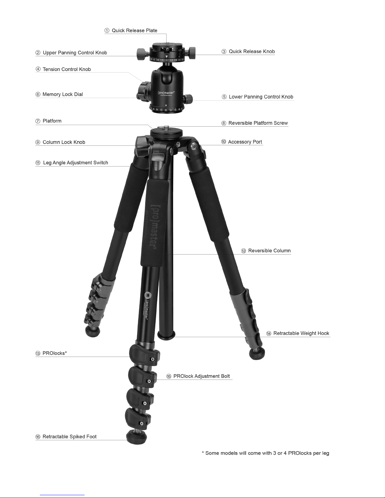
Extend the tripod’s Column (12) by loosening the Column Lock Knob (9) and pulling up on the column. Once
you have extended the column tighten the Column Lock Knob (9).
Notice the Reversible Platform Screw (8) in the tripod Platform (7) One side of the screw is 3/8” (larger side)
and the other side is a ¼"-20 type screw thread (smaller side). Be sure the 3/8” side is facing out from the
platform. If it is not, use a flathead screwdriver or coin to remove, reverse, and reinstall the screw using its
slot.
Align the bottom of the ball head with the Platform Screw (8) and turn the ball head in a clockwise direction
until it is tight against the Platform (7).
The underside of the Platform (7) has a small locking bolt with a female allen head. Locate the small allen key
in your tripod kit and use it to tighten the locking screw against the bottom of the ball head. This will prevent
the head from becoming loose on the Platform (7). You can now lower the tripod column.
Mounting the Quick Release platform to your camera
Locate the Quick Release Plate (1). It should have been packed in the small box with the ball head. Notice it
has a male ¼"-20 screw on one side. Align this screw with the female threaded port on the bottom of your
camera. Tighten the screw so the platform is snug. You can use the fold out handle on the screw head or insert
an allen key for more leverage while tightening. The quick release plate can be mounted to your camera in
any direction. The position of the plate will dictate the direction in which you mount your camera to the ball
head. It will either slide onto the ball head in a front-to-back motion or a side-to-side motion.
Mounting your camera
Loosen the Quick Release Knob (3). This opens the jaws of the quick release receiver on the ball head. Slide
your camera onto the head by aligning the Quick Release Plate (1) and top of the ball head. Once the plate is
centered in the jaws tighten the Quick Release Knob (3). This quick release system uses a safety latch, which
Page 2

will make a clicking noise as you slide the camera onto the head. It prevents your camera from falling off the
head when the jaws are loosened. Press the silver button on the top of the ball head when the jaws are open
and you are sliding the camera off to disengage the safety latch.
TRIPOD OPERATION
Adjusting and extending the legs
Place your hand near the top of a leg (just below the Leg Angle Adjustment Switch 11) and pull away from
the Column (12) until it stops at an angle from the rest of the tripod. When all 3 legs are pulled out to this first
position the tripod is in its most common leg-angle position. Each leg can be adjusted independently to a
different angle if you choose. To adjust a leg angle grip the top of the leg and place your thumb on the Leg
Angle Adjustment Switch (11). Slide and hold it down while pulling on the leg. Release the angle adjustment
control and continue pulling the leg until it stops at the next point. Do this again to achieve an even wider leg
angle. There are multiple leg angle stopping points. You may also angle each leg out completely so the tripod
will sit flat. When you are finished shooting push each of the legs back to their closed position for transport.
To extend the length of any leg flip open the PROlocks (13), pull on the leg sections, and then push the
PROlocks (13) closed. You can open each PROlock one at a time or all together. The PROlocks may require
slight adjustment from time to time to ensure a leg doesn't slip. If a leg is slipping open the particular
PROlock and use the included allen key to adjust its PROlock Adjustment Bolt (15). You can tighten it by
turning clockwise a very small amount. Now attempt to close the PROlock. If it is difficult to close, stop and
use the allen key to loosen the PROlock Adjustment Bolt (15) slightly. Please note that over tightening the
PROlock Adjustment Bolts (15) could lead to damage. Adjust them in small amounts until any slipping of leg
sections has stopped.
Extending and reversing the column / Using the weight hook
Loosen the tripod Column Lock Knob (9) and slide the Reversible Column (12) up or down to the desired
position. Tighten the Column Lock Knob (9) to hold the column in place. Notice the Retractable Weight Hook
(14) at the bottom of the column. It is retracted with spring tension. Pull it away from the column and hang
something on the hook, such as a camera bag, to add weight and stability to your Specialist tripod.
The Reversible Column (12) is a 2-piece unit. You will see a small seam on the Column (12) near the
Platform (7). Place a hand on each side of the seam and twist to unscrew the two parts of the Reversible
Column (12). Now you have a short column, which can be used for low angle shots. Or, you can loosen the
Column Lock Knob (9) and slide the column completely out of the tripod. Turn the column upside down and
reinsert it into the tripod thereby reversing the column. Be sure to securely hold your camera when the column
is reversed and the Column Lock Knob (9) is loose to avoid having your camera slide too fast and hit the
ground.
Please note, a tripod is always more stable when the legs are used to gain height rather than the column.
Practice using the 3 legs to achieve your desired height and only extend the column once the legs cannot go
any higher.
Adjusting the ball head
With your camera mounted to the ball head use the large Tension Control Knob (4) to adjust the ball head.
Loosen it to move your camera. Tighten it to lock your camera in place.
A small Memory Lock Dial (6) is located in the face of the Tension Control Knob (4). This allows you to
loosen the ball head over and over again to a specific tension thereby giving the right amount of control in
moving the head with a specific weight of equipment. To use the Memory Lock Dial (6) loosen it
Page 3

(turning is counter clockwise). Next use the Tension Control Knob (4) to set the right amount of tension for
your camera/lens combination. You should be able to adjust the position of your camera without it feeling too
loose but also without having to use too much force. Once you have found the right amount of tension, turn
the Memory Lock Dial (6) clockwise until it stops (Do not use a lot of force on this dial or you may damage
it). Next turn the Tension Control Knob (4) clockwise to lock your camera in place for photography. When
you wish to reposition your camera, gently turn the Tension Control Knob (4) counterclockwise until it stops.
This returns the ball head to the previously set memory lock position. Now you can reposition your camera
using the right amount of tension you previously set. To set a new memory lock point loosen the Memory
Lock Dial (6) until the Tension Control Knob (4) can be loosened enough for the ball head to move freely.
Then repeat the steps above to re-set the memory lock.
Included with the ball head is a second low-profile Memory Lock Dial. If you prefer to have the dial flush
with the face of the Tension Control Knob (4) you can switch the low profile version with the extended
version that comes installed. Both dials work the same way for setting a memory lock position.
In addition to the tension control your ball head has both upper and lower panning controls. Use whichever
you prefer to pan your camera. The Upper Panning Control Knob (2) helps when you wish to pan in a straight
line. Once you use the Tension Control Knob (4) to set the ball head to a level position, the upper panning will
maintain that straight, level line as you pan your camera with it. If you wish to pan the entire ball head use the
Lower Panning Control Knob (5).
Using the accessory ports
Two 3/8" threaded, female Accessory Ports (10) are located in the yolk of the tripod. Use these to connect
accessories such as flex arms, spigots, etc. With these accessories mounted you can hold items such as a
speedlight, LED light, reflector, etc. This kit also includes two reducing adapters, which can be used to
convert the Accessory Ports (10) to a ¼"-20 size.
Using the retractable feet
At the bottom of each of the 3 tripod legs you will find rubber feet with stainless steel spikes in the middle.
Turn these Retractable Spiked Feet (16) clockwise to expose the spikes for a better grip on certain surfaces.
Turn the rubber feet counterclockwise to hide the spikes and use the softer, more protective rubber bottoms.
ONE YEAR UNCONDITIONAL WARRANTY
If for any reason, this ProMaster product fails within ONE YEAR of the date of purchase, return this product
to your ProMaster dealer and it will be exchanged for you at no charge. ProMaster products are guaranteed for
ONE FULL YEAR against defects in workmanship and materials. If at any time after one year, your
ProMaster product fails under normal use, we invite you to return it to ProMaster for evaluation.
Made in China
WWW.PROMASTER.COM | FAIRFIELD, CT 06825
Page 4
 Loading...