


PROMAG
STARCREM 30/60 IngleseUTILIZZATORE (USER)
le macchine per il gelato
USE AND MAINTENANCE
INSTRUCTION MANUAL:
"CUOCICREMA" MACHINE
STARCREM 30/1 INV
STARCREM 60/1 INV
with R404A
USER INSTRUCTIONS
STARCREM 60/1 INVSTARCREM 30/1 INV
02 - 2002

STARCREM 30/1 INV - STARCREM 60/1 INV
2
PROMAG
The technical data for each machine model is
shown in the enclosed tables and on the data
plate located on the rear side of the machine.
This data is used as a reference when
performing inspections or checks.
Bar code
A = air condensation
W = water condensation
Manufacturer
PROMAG
Via Benaco 4
20098 San Giuliano Milanese
Milano Italy
Tel. 02 - 98296.1
Telefax 02 - 98.80.232
This plate is an exact
copy of that located on
the rear side of the
machine, for this reason
the manual forms an
integral part of the
machine and must be
kept together with it.
Safe machine operation is assured by correctly following the
instructions given in this manual. Therefore, we suggest you keep the
manual in a safe place where it can be readily consulted as required.
USER INSTRUCTIONS

PROMAG
GB
STARCREM 30/1 INV - STARCREM 60/1 INV
pag.
pag.
7/60
INSTRUCTIONS FOR USER
INSTRUCTIONS FOR TECHNICIAN-INSTALLER61/76
A
B
77/89pag.
SPARE PARTS
USER INSTRUCTIONS
3

STARCREM 30/1 INV - STARCREM 60/1 INV
4
INTRODUCTION
PROMAG
This manual gives all assembly, operating and
maintenance instructions required for assuring
excellent operating results and a long machine
service life.
Before starting to use the machine,
read these instructions and follow them
very carefully.
Please do not hesitate to contact us for
any assistance you may require.
Failure to abide by the norms included in this
manual will invalidate the guarantee.
If the machine is sold or otherwise put into another
person's possession,ensure that the manual
accompanies the machine therefore allowing the
new owner to correctly follow the operating
procedures and abide by the relative precautions.
The present "CUOCICREMA" machine,
is a multi-functional machine, destined exclusively
for pastry products (cream cooking) and ice cream
making (preparation and/or pasteurization of ice
cream mixture).
Never try to repair the machine yourselves,
as any attempt to make repairs by incompetent
persons will not only be dangerous but may also
cause serious injuries.
In the case of a malfunction, contact the distributor
from whom the machine was bought.
They can give you the address of the Authorized
Service Centre closest to you.
Only use original spare parts for any necessary
replacements.
If you decide to no longer use the machine,
we advise you to cut the electrical cord so that it
cannot be used (after disconnecting the plug from
the power socket).
In addition:
- Under no circumstances should the refrigerant
gas or compressor oil be allowed to escape and
thus contaminate the environment.
- See that the machine is disassembled and that
the parts are disposed of in accordance with the
national regulations in force.
Do not utilize the "CUOCICREMA" for any other use
other than that described above.
A similar use shall be considered improper.
This machine is designed to be used by adults.
Keep children away from the machine;
they should not be allowed to play with it.
Any attempt to modify this machine will not only
invalidate the guarantee but is also extremely
dangerous.
In order to assure efficient, correct machine
operation carefully follow the manufacturer's
instructions and only allow professionally qualified
personnel to perform any necessary maintenance.
This machine contains H.C.F.C. gas which could be
harmful to the environment in the case of incorrect
maintenance operations or disassembly.
Therefore, any such operations must be done in
accordance with the national regulations in force,
and must only be performed by authorized
maintenance personnel.
PROMAG reserves the right to make any and all
modifications reemed necessary in order to keep
the machine updated - technically or otherwise as well as to allow it to meet the requirements of
certain individual countries.
For any additional information or technical help you
may require, please contact your authorized service
centre.
USER INSTRUCTIONS

PROMAG
GB
This manual is made
up of three parts:
Part A:
instructions and information for
the User and
the Technician-Installer
Copy of the conformity declaration found with the machine
I) La ditta PROMAG, con la firma del suo delegato alla sicurezza del prodotto, dichiara sotto la propria esclusiva responsabilità
che la macchina:
2) The company PROMAG hereby declares under its own sole responsibility, through the signature of its product safety manager, that
the machine:
3) La société PROMAG, parla signature de son délégué à fa sécurité du produit, déclare sous sa propre et exclusive responsabilité
que la machine:
4) Die Firma PROMAG erklärt unter ihrer ausschließlichen Verantwortung mit der Unterschrift ihres Beauftragten für die ProduktSicherheit, daß die Maschine:
5) Het bedrijf PROMAG verklaart hierbij uitsluitend op eigen verantwoordelijkheid, door middel van de handtekening van zijn
manager produktveiligheid, dat de machine:
6) La empresa PROMAG, mediante la firma de su encargado para la seguridad del producto, declara bajo su propia y exclusiva
responsabilidad que la máquina:
7) A firma PROMAG, com a assinatura do seu delegado para a segurança do produto, declara sob a própria e exclusiva
responsabilidade que a máquina:
Part B:
instructions and information for
the Technician - the Shipper
the Installer - the Maintenance Man the Repair Man
STARCREM 30/1 INV - STARCREM 60/1 INV
Part C:
electrical diagrams
and spare parts
8) Firmaet PROMAG erklærer hermed, gennem den produktsikkerhedsansvarliges underskrft og under eget ansvar, at maskinen:
9) Yhtiö PROMAG vakuuttaa täten tuoteturvallisuudesta vastaavansa allekirjoittamana ja omalla vastuullaan, että kone:
10) Härmed intygar företaget PROMAG, genom underskrift av sin produktsäkerhetsansvarige och på eget ansvar, att maskinen:
11) Firmaet PROMAG erklærer herved, ved den produktsikkerhetsansvarliges underskrift og under sitt eneansvar, at maskinen:
STARCREM 30/60 Matr..................
1) preparatore e pastorizzatore di prodotti per pasticceria e gelateria, è conforme ai requisiti essenziali previsti dalle Direttive CEE
89/392, 91/368, 89/336, 73/23 e 93/68.
2) preparing and pasteurizing machine for pastry and ice cream products, complies with the essential requirements indicated in
EEC directive 89/392, 91/368, 89/336, 73/23 and 93/68.
3) machine pour la prèparation et la pasteurisation de produits pour pâtisserie et glacerie, est conforme aux conditions requises
essentielles prévues par les directives CEE 89/392, 91/368, 89/336, 73/23 et 93/68.
4) Maschine für die Vorbereitung und Pasteurisierung von Konditorei- und Speiseeisprodukten, den grundlegenden, von den
EWG-Richtlinien 89/392, 91/368, 89/336, 73/23 und 93/68 gestellten Anforderungen genügt.
5) machine voor het bereiden en pasteuriseeren van producten voor gebak en consumptieijs, voldoet aan de essentiële
voorwaarden vervat in de EEG-Richtlijnen 89/392, 91/368, 89/336, 73/23 en 93/68.
6) preparador y pasteurizador de productos para pastelería y helados, es conforme a los requisitos esenciales prevístos por las
Directivas CEE 89/392, 91/368, 89/336, 73/23y 93/68.
7) Preparador e pastorizador de produtos para confeitaria e sorveteria, é feita conforme os resuisitos principais previstos pelas
Normas CEE 89/392, 91/368, 89/336, 73/23 e 93/68.
8) maskine til tilberedning og pasteurisering af konditorkager og is-produkter overensstemmer med de væsentligste krav anført i
EU direktiv 89/392, 91/368, 89/336, 73/23 og 93/68.
9) konditoria-ja jäätelötuotteiden valmistus-ja pastörointikone noudattaa EU direktiiveissä 89/392, 91/368, 89/336, 73/23 ja 93/68
ilmaistuja olennaisia vaatimuksia.
10) för tillagning samt pastörisering av bakverk och glassprodukter uppfyller de väsentliga kraven i EU-direktiv 89/392, 91/368, 89/
336, 73/23 och 93/68.
11) maskin for tilberedning og pasteurisering av deig-og iskremprodukter er i samsvar med de vesentligste krav angitt i EUdirektiv 89/392, 91/368, 89/336, 73/23 og 93/68.
The operating instructions form an integral part of the machine. - The machine user must not perform any of the operations
described in parts B and C; these must only be carried out by a qualified technician. - The user is therefore informed that if he
attempts to do so he will compromise the safety and health standards with which the machine is designed and built.
USER INSTRUCTIONS
5

STARCREM 30/1 INV - STARCREM 60/1 INV
6
INFORMATION FOR THE USER AND TECHNICIAN-INSTALLER
PROMAG
General Information
Thank you for having chosen this machine.
Please read the instructions in this manual
carefully; they will assure long machine
service life.
We can guarantee that only the very best
materials have been used for this machine,
that it has been very carefully tested,
and that we are always ready to serve and
assist you in the best possible way.
IMPORTANT PRECAUTIONS
When the machine is being installed,
make sure that a disconnecting switch is
installed on the power supply line by a qualified
technician.
Always ensure that the plug is disconnected
from the mains before putting your hands inside
the machine or before performing cleaning or
maintenance operations.
HELPFUL ADVICE
When manufacturing your products only use
the very best ingredients, in order to fully
satisfy even your most demanding customers.
Obtain all basic ingredients from well-established
firms that have a proven reliability.
When making your products follow the
instructions very carefully and do not try
to change the recipe in any way.
Always keep the machine spotlessly clean.
(Contact a qualified technician whenever
maintenance is required).
Never clean the machine using a water jet
under pressure.
Always ensure that the plug is disconnected
from the mains before removing the housing,
side panels or any other protection in order to
carry out any operation within the inner part
of the machine.
(Such operations must only be performed by a
qualified technician)
For all necessary repair work always contact one of PROMAG's assigned maintenance
firms.
If any of the operating, cleaning or maintenance instructions given in this manual are not
carefully followed, and an accident occurs, PROMAG cannot be held responsible.
Thanking you once again, we wish you all the best.
USER INSTRUCTIONS

PROMAG
GB
A 1
STARCREM 30/1 INV - STARCREM 60/1 INV
INSTRUCTIONS FOR THE USER AND THE TECHNICIAN-INSTALLER
Environmental conditions
page
A
8
A 2
A 3
A 4
A 5
A 6
A 7
A 8
A 9
A 10
A 11
A 12
A 13/A 14
A 15
A 16
A 17
A 18/A19
A 20
Machine description
Number of users and type of work
Productive cycle
Operating modes
Precautions
Safety devices
Machine use
Description of external components
Correct use of product dispensing cock
Scraping blades
Description of internal components
Dangerous points on the machine
Protection measures for dangerous machine areas
Risks information
Recommendations on prevention measures to be adopted
Installation/Use of machine
Machine preparation
page
page
page
page
page
page
page
page
page
page
page
page
page
page
page
page
page
9
10
10
10
11
12/14
15
16/19
20/21
22
23
24/25
26
26/27
27/28
29
29
A 21
A 22
A 23
A 24
A 25
A 26
A 27
A 28
A 29
A 30
A 31
A 32
A 33
A 34/45
A 46
A 47
A 48
Operation
Program check
Inverter manual operation
Inverter semiautomatic operation
Cycle A Pastry cream
Cycle B High temperature pasteurization for ice cream mix
Cycle C Low temperature pasteurization for ice cream mix
Cycle D solidification of plain chocolate
Cycle G Bavarian cream
Cycle H Fruit jam
Cycle I Cooling
Cycle L Manual Cooking
Cycle M - N Personalized
Significance of programmable parameters
Stop modes
Black out
Anomalies
page
page
page
page
page
page
page
page
page
page
page
page
page
page
page
page
page
30/31
32
33
33/34
34/35
36/37
38/39
40
41
42
43
44
45
46/52
53
53
54
A 49
A 50
A 51
A 52
A 53
A 54
Operations to be performed after use
Dismantling
Technical characteristics
Dimensions
Programming table inverter Starcrem 30/1 INV
Tabella programmazione inverter Starcrem 60/1 INV
USER INSTRUCTIONS
page
page
page
page
page
page
55
56
57
58/59
60
60
7

STARCREM 30/1 INV - STARCREM 60/1 INV
8
A 1 - ENVIRONMENTAL CONDITIONS
The machine must not be kept in a room where the
temperature can drop below 0° C.
The machine is not designed for installation in
atmospheres where there is a risk of explosion.
A 1.1
MACHINE OPERATING NOISE LEVELS
The acoustical pressure level produced by the
machine is shown on the enclosed technical
diagram.
Measurements were made throughout the operating
cycle using a class 1 instrument held
at the point where the user stands in relation to the
machine (as indicated in the sketch).
PROMAG
Level of continuous acoustical pressure measured
with a ponderation "A" filter.
STARCREM 30 - STARCREM 60
dB (A) 61 ÷ 65
USER INSTRUCTIONS

PROMAG
GB
Significance of trade-mark names
STARCREM 30 = 30 litres
STARCREM 60 = 60 litres
Function:
MULTIFUNCTIONAL MACHINE TO BE USED EXCLUSIVELY FOR PASTRY
PRODUCTS (CREAM COOKING) AND ICE CREAM MAKING
(PREPARATION AND/OR PASTEURIZATION OF ICE CREAM MIXES,
MAINTENANCE AND/OR MATURING OF ICE CREAM MIXES).
For technical data of machines, see enclosures.
Machine components
The machine is complete with a main frame with a stainless
steel structure, the base of which is provided with four
wheels, one at each corner.
STARCREM 30/1 INV - STARCREM 60/1 INV
A 2 - MACHINE DESCRIPTION
On opening any one of the two lids, all machine
operations will be interrupted and "OPEN" will appear
on the display.
As already mentioned, the motors are mounted on
motor bearings.
Above are served by a magnetic safety microswitch.
On lifting the motor bearings, all operations of the
machine are interrupted and "OPEN" will appear on
the display.
The frame is parallelpipedal, containing the cylinder,
electric box and cooling system.
The cylinder is mounted vertically, disposing of a cooling
system on external surface (containing refrigerating gas),
a heating system (containing water) and a deep basin
(containing water), in which resistances are located, and
whereby heating is carried out with "bain-marie" method,
a particular characteristic of Promag.
The low speed and high speed mixer shafts are
immersed in the cylinder. They are connected to
respective motors, the latter being assembled onto motor
bearings.
The main cooling system elements comprise: a
compressor, a condenser, a thermostatic valve and a
compressor pressure switch.
The cylinder diposes of an outlet which is located on the
front side of the machine. This opening may be closed
with a cock, provided with a piston with two O-ring seals.
The manual cock commanding the small washing
shower unit is located on the upper left front side of
the machine.
The small shower unit is situated on the bottom of the
cylinder in the right-hand corner.
A control panel, facing inwards, is located on the upper
front side of the machine, where an electronic card
may be found.
Control buttons are accessible on control panel.
The electric box, as described above, is also included
inside the frame and is positioned on the rear side of
same.
Water connections for cooling system are present on
the rear side of the machine, in addition to those for
drinking water for small shower unit.
Electric feed cables are also present.
Above closes outlet at the level of container edge. This
solution guarantees a perfect hygiene, as the mix
contained in the cylinder has no chance of stagnating in
the stub pipe.
The outlet diameter may also be reduced for the
discharge of extremely liquid mixes.
Two half-lids are located at the upper part of the cylinder,
served by two magnetic safety microswitches.
USER INSTRUCTIONS
9

STARCREM 30/1 INV - STARCREM 60/1 INV
10
A 3 - NUMBER OF USERS AND TYPE OF WORK
The machine is designed to be used by one
operator only, in charge of loading product to be
processed, setting productive cycle and
subsequent recovery of product through cock.
A 4 - PRODUCTIVE CYCLE
The user opens the front half-lid (34) and pours the
product into the cylinder, closing same.
He starts up productive cycle, after having set
appropriate parameters with buttons (36).
He unloads product by using special cock (37).
PROMAG
A 5 - OPERATING MODES
The machine is designed for a single type of
continuous operation, on pressing heating or
maintenance buttons.
Machine stops automatically.
Machine is also designed for manual operation on
pressing buttons for low speed stirring, intermittent
low speed stirring, high speed stirring.
USER INSTRUCTIONS

PROMAG
GB
STARCREM 30/1 INV - STARCREM 60/1 INV
A 6 - PRECAUTIONS
Danger points
The machine has certain danger points and areas where
accidents may occur if the following precautions are not
observed.
- It is forbidden and very dangerous to approach machine
cylinder when same is turned on or in motion.
- It is forbidden and very dangerous to carry out
any repairs on system, whether mechanical or electrical,
when the machine is functioning.
Refer to enclosures for electric and water systems.
- It is forbidden to use the machine without operatorís
supervision.
- It is forbidden and very dangerous to come too near
and/or touch with any part of the body and/or any type of
object the shaft bars: low speed and high speed mixers
project from cylinder covers
until reaching motor bearings.
For the same reason do not approach relative motors
from rear side of motor casing.
- It is forbidden and very dangerous to introduce parts of
the body or any type of object into the product outlet.
- It is dangerous to touch machine ON/OFF wall switch
with wet hands.
- It is strictly forbidden to open electric box.
- It is forbidden and very dangerous to approach
the machine with magnetic materials, as they
would interfere with magnetic safety microswitches
located under the two cylinder half-lids and under the
right shoulders of the motor bearings
(For the user only)
It is forbidden and very dangerous for user to carry out any intervention which should
be done by a TECHNICIAN/INSTALLER.
Removal of protective coverings and access to internal parts of machine, in addition to all internal
maintenance operations, repairs, installation, transport and unpacking must be
carried out by qualified personnel.
USER INSTRUCTIONS
11

STARCREM 30/1 INV - STARCREM 60/1 INV
12
A 7 - SAFETY DEVICES
PROMAG
A 7.1
Three magnetic microswitches are mounted onto the
STARCREM machines (19) (20) (21).
Microswitch (19) is located on the front left-hand side
under the cylinder.
Microswitch (20) is located on the rear right-hand
side under the cylinder.
Microswitch (21) is located on the rear left-hand side
under the cylinder.
Their purpose is to block any machine operation
should the front half-lid [(microswitch (19)], motor
bearings [(microswitch (20)], rear half-lid
[(microswitch (21)], be opened or lifted with the
machine in operation.
22
A 7.2
There is a machine stop button (7) located on the
control panel at the front of the machine which, when
pressed, stops any machine operation.
A 7.3
- 12 Volt control panel.
21
19
22 Blocking device for motor bearings
20 36
7
21 Rear left-hand microswitch
19 Front left-hand microswitch
20 Rear right-hand microswitch
USER INSTRUCTIONS

PROMAG
GB
A 7.5
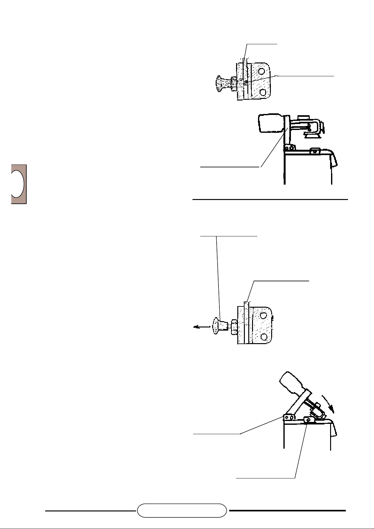
The STARCREM machines also have a safety device
to block the motor bearings (22).
The purpose of this is to prevent motor bearings falling
onto cylinder plane, should the latter be lifted for either
cleaning of mixer shafts or for any other reason.
A 7.5a
Normal position of motor bearings with machine in
operation. The motor bearing leans on cylinder plane
and disconnected blocking device.
STARCREM 30/1 INV - STARCREM 60/1 INV
Motor bearing
A 7.5b
Turnover phase of motor bearings.
The motor bearing may be lifted subsequent to
unscrewing of closing handwheel screws.
Perform above operation with extreme care, so that
motor bearing does not fall on cylinder plane,
subsequently hitting operator and causing serious
damage.
Blocking
device
Hinge pin
Cylinder plane
Until motor bearing is not in a vertical position, the
relative safety blocking device will not be activated;
therefore, as already mentioned, it is the operatorís
responsibility to take precautions, utilizing the
necessary measures to prevent risks of crushing,
entangling, or cutting with regard to persons, animals
or objects.
Closing handwheel
USER INSTRUCTIONS
13
STARCREM 30/1 INV - STARCREM 60/1 INV
14
PROMAG
A. 7.5c
Motor bearing entirely upturned: motor bearing has
been completely lifted, therefore now in vertical
position. Only in this position will the blocking
security device be activated, causing the block pip
to protrude.
In this manner, the motor bearing cannot fall onto the
cylinder plane and cleaning and washing operations
may be safely performed.
However, it is always necessary to check that above
device is functioning properly, together with wear of
same.
Should any deterioration be detected, please
contact authorized technical service.
Motor bearing left
shoulder
Blocking pip
Motor bearing in
vertical position
A. 7.5e
Closing of motor bearing on cylinder plane.
In order to carry out this operation, it is necessary to
unblock security device.
With the right hand, firmly maintain motor bearing in
vertical position; contemporarily pull the security
device knob towards the left with the left hand.
Slightly lower motor bearing, until block pip grazes
over left shoulder of motor bearing. In this position,
safety block may no longer be activated.
Firmly grip motor bearing with both hands,
subsequently lowering same onto cylinder plane.
Carry out this operation extremely carefully, avoiding
that motor bearing falls abruptly onto cylinder plane,
subsequently hitting operator and causing serious
damage.
When closing motor bearing, it is operatorís
responsibility to be careful, taking necessary
precautions to prevent risks of crushing, entangling
and cutting with respect to persons, animals or
things.
When the motor bearing is on the cylinder plane,
block it with two closing handwheels.
Safety device knob
Motor bearing left
shoulder
Hinge pin
Closing handwheel
USER INSTRUCTIONS

PROMAG
GB
STARCREM 30/1 INV - STARCREM 60/1 INV
A 8 - MACHINE USE
Use according to norms.
STARCREM machines are expressly designed to
cook cream, being multifunctional and only
destined for pastry products (cream cooking), ice
cream making (preparation and/or pasteurization of
ice cream mixes), maintenance and/or maturing of
ice cream mixes.
Use for any other purpose will not conform to the
norms.
The manufacturer is not responsible for any
damages deriving from improper use.
Any risks will be borne by user.
Manufacturerís safety, operational and maintenance
regulations must be observed.
The norms in force regarding accident prevention
and other acknowledged technical safety
regulations must also be observed.
Only properly trained and qualified personnel may
use, maintain or repair the machine.
The machine is mainly manufactured in stainless
steel AISI 304, together with plastic material as for
the food industry.
Any arbitrary modifications made to the machine will
exonerate manufacturer from any eventual damages
deriving therefrom.
The machine may only be used with original
accessories and spare parts made by the
manufacturer.
USER INSTRUCTIONS
15

STARCREM 30/1 INV - STARCREM 60/1 INV
16
A 9 - DESCRIPTION OF EXTERNAL COMPONENTS (front view)
PROMAG
35) Rear half-lid
34) Front half-lid
40) Hinge
41) Closing handwheel
43) Shower cock
45) Outlet for
dense products
39) Motor bearing
38) Motor casing
42) Small shower
36) Control panel
37) Product outlet cock
44) Slide
47) Fixed rear wheels
48) Rotating front wheels
A 9 - DESCRIPTION OF EXTERNAL COMPONENTS
(top view without motor casing)
49) Motor bearing
blocking device
46) Outlet for
liquid products
USER INSTRUCTIONS

PROMAG
GB
STARCREM 30/1 INV - STARCREM 60/1 INV
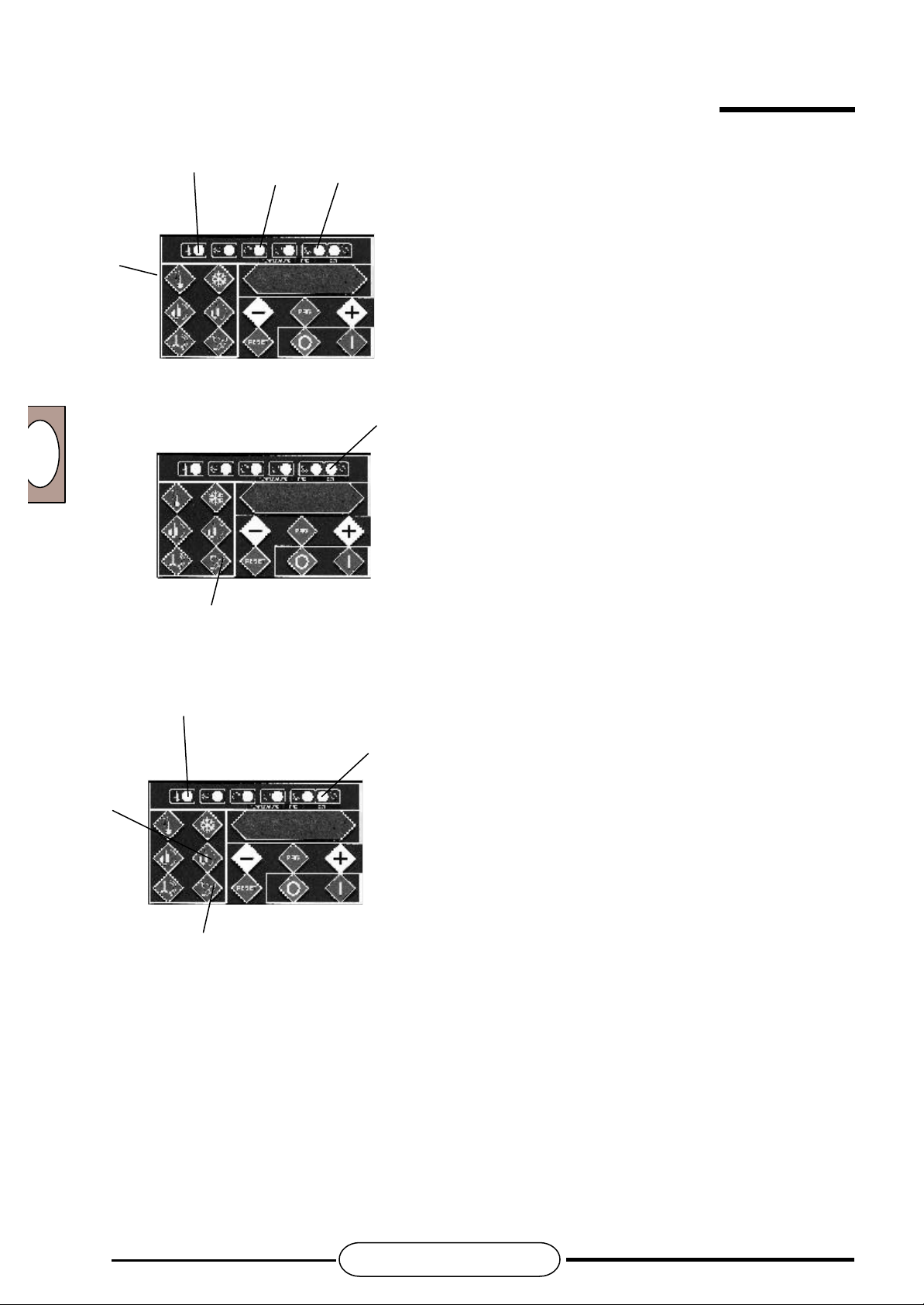
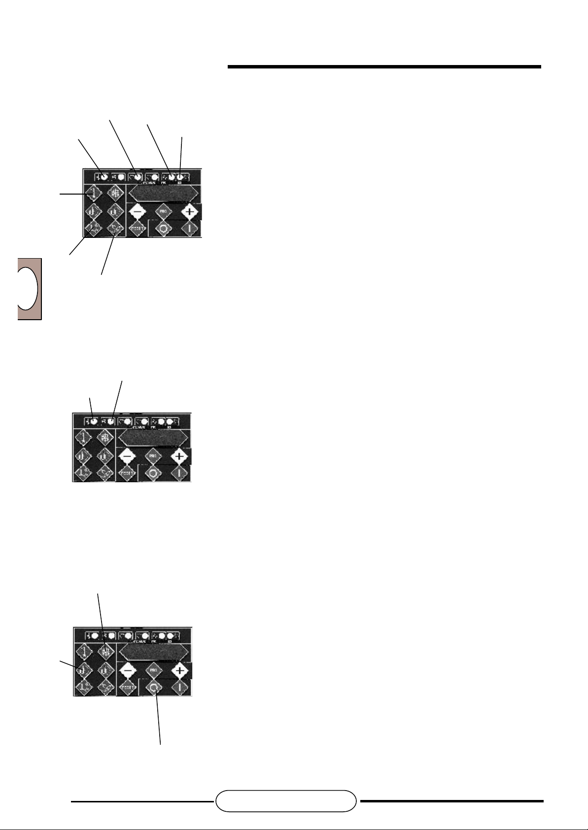
A 9 - DESCRIPTION OF EXTERNAL COMPONENTS (Control panel )
15) ON-OFF low speed motor led
14) Start-up led for cooling and
maintenance cycle
2) Start button for cooling and
maintenance cycle
13) Start-up led for
cooking cycle
1) Start button for cooking
cycle
3) Low speed motor
ON-OFF button
16) Manual start-up led for low
speed intermittent motor
17) High speed motor ON-OFF led
6) Button for
parameter
increase
7) High speed motor
ON-OFF button
4)Low speed intermittent
motor manual start-up
button
8) Bell setting button
5) Button for parameter
reduction
9) Reset
button
12) Program button
10) Emergency
stop button
USER INSTRUCTIONS
17

STARCREM 30/1 INV - STARCREM 60/1 INV
18
A 9 - DESCRIPTION OF EXTERNAL COMPONENTS PRODUCT OUTLET COCK
Cock security lock
Piston guide rod
PROMAG
Bush
Piston bearing
Setscrew
Outlet lock for liquid mixes
Knob
Piston rod
OR Seal
Cylinder
Outlet for dense mixes
Piston guide rod bearing
Outlet for liquid mixes
USER INSTRUCTIONS

PROMAG
GB
27) Wall ON/OFF switch
STARCREM 30/1 INV - STARCREM 60/1 INV
A 9 - DESCRIPTION OF EXTERNAL COMPONENTS (rear view)
25) Electric cable
for high speed
mixer motor
28) Electric cable
26) Electric cable
for low speed
mixer motor
29) Air extraction fan
30) Drinkable water
inlet for small
washing shower
31) Cooling system
water inlet
In order to avoid mineral deposits in the tubes and condenser, caused by water hardness, it is
recommended to install a water softener.
32) Water outlet
USER INSTRUCTIONS
19

STARCREM 30/1 INV - STARCREM 60/1 INV
20
A 10 - CORRECT USE OF PRODUCT DISPENSING COCK
In order to use the product dispensing cock correctly,
the following must be carried out:
begin productive cycle after having carried out cleaning
operations indicated in specific paragraph.
However, remember that mechanical parts in contact with
food must be perfectly sterilized, whilst those in motion
or sliding must be subsequently lubricated,
using advised products or similar.
A - Check that guide rod, piston bush and 2 OR
seals are duly lubricated. Push piston guide rod bearing
against slide.
Tighten the dowel on the right-hand side with
special setscrew wrench.
B - Place cock safety lock in vertical position.
C - Place liquid mix outlet lock in downward position.
D - Assemble piston group onto guide rod with piston bush.
Centering of bush with rod should be carried out carefully,
thereby avoiding any damage to bush during introduction,
wearing out external edges of same.
Cock safety lock
Piston
Piston bush
Guide rod
PROMAG
Liquid mix outlet
lock
Setscrew
OR seals
E - Screw setscrew until contact is made with guide rod.
A 10.2
Cock disassembly
Repeat previous operations in opposite sense.
A 10.3
Cock closing
A - Push the piston group towards the dense mix outlet.
The movement direction must be perpendicular to outlet.
IN NO WAY MUST GUIDE ROD OR PISTON GROUP BE FORCED
IN DIFFERENT DIRECTION, as disalignment of guide could be
caused, with consequential erroneous centering of piston in outlet.
Assembled cock
B - Introduce piston into the outlet with a smooth movement, avoiding
that any metallic parts of the two components come into contact with
one another. Push piston until reaching stop.
C - Lower the cock safety lock.
D - This will guarantee closing position, also in the presence of strong
mixing vibrations in the cylinder towards outside.
USER INSTRUCTIONS
Working surface
PROMAG
GB
A 10.4
Extraction of liquid mix
A - Once the cock is closed, pull the lock upwards to discharge
liquid mixes.
B - Place the cock safety lock in vertical position.
C - Pull piston group in perpendicular direction with respect to
outlet, until lock for liquid mix outlet rests against the setscrew.
At this point, the mix will be discharged from the lower part of the
outlet, through the stub pipe with a diameter suitable for liquid
mixes.
Attention:
After every extraction of liquid mixes, wash the cock
perfectly, using the proper swabs. Subsequently, sterilize
using the proper hygienic solutions.
A 10.4
Extraction of dense mix
A - When liquid mix is ready to be discharged, lower outlet
lock.
STARCREM 30/1 INV - STARCREM 60/1 INV
Cock
B - Pull piston group in perpendicular direction with respect
to outlet, until same rests against the setscrew.
C - Very slightly turn piston group around guide rod.
D - Push piston group, leaning it on outlet.
At this point, a small quantity of the mix will be discharged
from the lower part of the outlet through the pipe stub with a
diameter suitable for liquid mixes, whilst the majority will be
discharged from the front part of the outlet for dense mixes.
Attention:
After every extraction of dense mixes, wash the cock
perfectly, using the proper swabs. Subsequently,
sterilize using the proper hygienic solutions.
A 10.5
ATTENTION
Never unscrew cock screws. The only screw which
may be unscrewed, for cleaning purposes, is that
supporting the piston guide rod.
Cock
USER INSTRUCTIONS
21

STARCREM 30/1 INV - STARCREM 60/1 INV
22
A 11 - SCRAPING BLADES
A 11.1
The slow speed beater shaft is provided with two blades made of teflon,
which function is to scrape the tank wall and at the same time to stir the
product.
A 11.2
Blade assembly
In order to assemble the blades, the motor bearing must
be in vertical position.
With regard to above, reference should be made to
paragraphs on safety devices, dangerous points on the
machine and other risks, inviting the user, technicianinstaller or any other person to strictly follow instructions
contained therein.
PROMAG
Scraping blade for cylinder wall
No responsibility will be assumed for improper use of
the machine or operations carried out which are not in
compliance with safety regulations.
The blades are hooked on, mating hole with head,
pushing blade until resting against slot.
A 11.2
Disassembly of blades
Proceed as indicated for assembly, but with reverse
sequence.
Scraping blade for cylinder bottom
USER INSTRUCTIONS

PROMAG
GB
STARCREM 30/1 INV - STARCREM 60/1 INV
Informative notes for user, but strictly concerning technician-installer
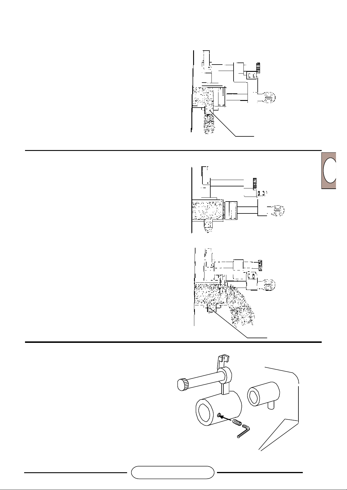
A 12 DESCRIPTION OF INTERNAL COMPONENTS STARCREM 30 - 60
Cylinder
Dehydrator filter
Electric box
Security valve
Humidity indicator
Thermostatic valve
Warmgases solenoid valve
Pressure switch
Compressor wiring box
Gas tap (high
pressure mains tap)
Compressor
Pressure control valve
Electrovalve
Water discharge filter
Water condenser
Filling group
Electrovalve
USER INSTRUCTIONS
23

STARCREM 30/1 INV - STARCREM 60/1 INV
24
A 13 - DANGEROUS POINTS ON THE MACHINE
Definition of dangerous areas with relative warning modalities;
general description of protection measures adopted.
PARTS IN MOTION TAKE CARE OF
HANDS
A 13.1)
Danger of entangling and dragging.
Danger of cutting and crushing.
- High speed mixer shaft.
- Low speed mixer shaft.
- Blades.
- Product outlet with cock open or
disassembled.
PROMAG
A 13.4)
Dangerous electric voltage
- General electric panel.
- Motor compressor.
- Motors.
A 13.2)
Thermal danger:
hot and cold parts.
- Cooling system.
- Compressor connection tube,
condenser.
- Cylinder.
A 13.3)
Dangerous pressure:
- Cooling system under
pressure.
USER INSTRUCTIONS

PROMAG
GB
STARCREM 30/1 INV - STARCREM 60/1 INV
A 14 - DANGEROUS POINTS ON MACHINE
with motor bearings in vertical position and during opening
High speed mixer shaft
Low speed mixer shaft
Magnetic
microswitch
In order to lift motor bearing bracket, grip onto
Magnetic
microswitch
A 14.1)
Danger of cutting, entangling, crushing, dragging
- High speed mixer shaft
- Low speed mixer shaft
- Blades
- Left and right brackets of motor bearing
- Motor bearing
- Motor casing
- Cylinder edge
- Cylinder bottom
-Small fans of high speed mixer shaft.
Never grip onto high speed mixer shaft as this
operation would unbalance same and jeopardize
ATTENTION:
low speed mixer shaft.
operation.
Magnetic
microswitch
USER INSTRUCTIONS
25

STARCREM 30/1 INV - STARCREM 60/1 INV
26
A 15 - PROTECTION MEASURES FOR DANGEROUS MACHINE AREAS
PROMAG
A 15.1
The machine is equipped with a casing, preventing
access to internal part of machine, together with
moving parts.
Above casing is fixed with screws.
Casing (fixed with screws) may only be removed by
qualified personnel and authorized by Promag.
A 15.2
Manual access to cylinder outlet is very difficult and
nevertheless it is only possible when cock has been
disassembled or is in open position.
The distances of the liquid mix and dense mix outlets
from the lateral surface of the cylinder and therefore
from the scraping blades and relative low speed shaft
is considerable, thereby preventing access of body
parts and avoiding above-mentioned dangers.
A 15.3
Access to high speed mixer shaft and low speed mixer
shaft is possible only by lifting the front and/or rear halflid and/or motor bearing. With above operations, the
three safety magnetic microswitches interrupt all
machine operations, stopping rotation motion of same.
A 15.4
During cleaning phase of two shafts, the motor bearing
is lifted in vertical position.
It is impossible for same to fall backwards, thereby
crushing hands or upper limbs of operator, as in this
position the motor bearing lock device is automatically
activated, as previously described.
A 16 - INFORMATION ON OTHER RISKS IMPOSSIBLE TO ELIMINATE,
DESPITE MEASURES ADOPTED BY DESIGNER
Other risks involved using the machine are:
A 16.1
Danger of entangling and dragging.
Please note that it is absolutely forbidden to come
into contact with mobile parts inside the cylinder (high
speed mixer shaft, low speed mixer shaft) whilst the
machine is functioning, with any object whatsoever or
part of the body, as this could result in jamming,
crushing and/or cutting.
Danger exists if, for imprudent cleaning operations
with cleaning rods or similar and with the machine still
in operation, one attempts access to cylinder through
the liquid mix outlet or through the cylinder pipe
union, with tap either disassembled or open. In case
of danger, press the STOP button.
A 16.2
Dangerous pressures
The cooling system still remains under pressure
even when the machine is off.
Before carrying out maintenance operations on same,
eliminate this type of risk.
A 16.3
Thermal danger
Please note that on water and cooling systems both hot
and cold mechanical parts exist, protected by special
casings.
Besides, any contact with same is absolutely
forbidden, thereby avoiding burning risks.
Danger exists in the case of repair and/or with internal
inspection of machine when same is still functioning or
recently turned off. (Remember that these operations
must be carried out by qualified personnel, authorized
by Promag).
Danger also exists when processing mixes whose final
heating temperature is high and when cylinder lid is
opened for product inspection.
If user is near the cylinder, steam produced by liquid
mix may hit his face, causing burning. Danger also
exists if hands or other parts of the body are introduced
into the mix. It is absolutely forbidden to introduce
hands or any other part of the body into the hot mix. It
is absolutely forbidden to bring face or other parts of
the body near the cylinder.
In case of danger, press the STOP button.
USER INSTRUCTIONS

PROMAG
GB
A 16.4
Danger of cutting, entangling and crushing
During washing and cleaning operations, the motor
bearing is lifted and placed in vertical position. As
already mentioned, there is no danger of same falling
and crushing hands or upper limbs, as in this position
the motor bearing lock device is automatically
activated, as described above. Danger still exists,
however, if, during opening of motor bearing, operator
fails to take a firm grip of same, owing to wet hands or
similar, or lacks sufficient strength.
In this case, the motor bearing would fall on the
cylinder plane, hitting any object in its way, causing
crushing, cutting and entangling between itself and the
edge of the cylinder, in addition to cylinder plane.
It is absolutely forbidden to place the machine in an
environment unsuitable for its appropriate use.
It is absolutely forbidden to move the machine and/or
its components in an irregular manner, thereby
jeopardizing its stability and reliability.
In case of danger, push the STOP button.
A 16.5
Danger also exists when approaching the machine
(especially with motor bracket open) with magnetic
materials, as same would interfere with safety magnetic
microswitches located under the two cylinder half-lids
and under the right shoulder of the motor bearing. In
this case, if the machine were operating, the two
STARCREM 30/1 INV - STARCREM 60/1 INV
motors would start up, causing the respective shafts to
rotate, dragging anything in contact around with them.
It is absolutely forbidden to approach the machine with
magnetic materials or interfere with safety magnetic
switches on purpose.
In case of danger, press the STOP button.
A 16.6
Dangerous electric voltage
During repair and/or maintenance operations,
(operations nevertheless permitted only by qualified
personnel, authorized by Promag), it is possible that
technician needs access to control panel, motor
compressor, motors or any other electric or
electromechanical component.
Danger exists if these operations are carried out without
having previously cut off electricity from mains, using a
special disconnecting device provided for during
machine installation, or even worse, when the machine
is in operation.
It is absolutely forbidden to gain access to electric and/
or electromechanical parts, without having previously
turned off machine with special disconnecting device.
In case of danger, press the STOP button.
A 17 - RECOMMENDATIONS ON PREVENTION MEASURES TO BE ADOPTED
A 17.1
Safety regulations.
In order to maintain the machine in a perfect state
and guarantee a safe operation for user, we advise
that following regulations are scrupulously followed.
This machine must only be used for the purpose for
which it has been originally designed.
Any other use is to be considered improper and
therefore dangerous.
During handling, loading and unloading of machine, be
very careful in choosing lifting points.
Do not leave machine exposed to atmospheric agents
(rain, sun, etc.).
Do not permit machine to be used by children or
inexperienced persons.
Machine must not be used by untrained personnel.
Maintain machine in perfect operating state, always
utilizing the various protections provided for, having
periodical maintenance carried out by professionally
qualified personnel.
Before connecting the machine, control that plate data
corresponds to that of electric and water distribution
network, (the plate is situated at the rear part of the
machine).
USER INSTRUCTIONS
27

STARCREM 30/1 INV - STARCREM 60/1 INV
28
PROMAG
Assure that machine is perfectly grounded, as foreseen
by safety regulations in force.
It is necessary that this fundamental safety requisite is
respected: in the case of doubt, ask for a careful
control of the plant by professionally qualified people.
Check that plant electric power is suitable to the
maximum absorbed power of the machine.
In case of doubt, revert to a qualified person, who must
control that the plant cable section is suitable for
absorbed power of machine.
Do not touch the machine with either wet or damp
hands or feet
Do not use the machine barefoot
Do not use extensions in rooms destined for
bathrooms or shower rooms
Do not pull the feed cable to disconnect the machine
from mains.
A 17.2
In order to avoid dangerous overheating, it is
necessary to wind up the entire feed cable.
Before carrying out any maintenance operation,
disconnect machine from mains, using plant
disconnecting device.
temperature of 100° C and well secured to the drain collector.
For cleaning operations, scrupulously follow
instructions laid down by manufacturer.
Do not block suction or dissipation grilles.
After having disconnected the machine, only qualified
personnel may have access to control panel.
When washing stainless steel, it is absolutely
In case of breakdown and/or poor functioning of
machine, disconnect the main disconnecting device,
abstaining from any attempt to repair or intervene
directly, reverting only to professionally qualified and
authorized personnel.
Eventual product repair will have to be carried out by
manufacturing company or by an authorized Service
Centre, only using original spare parts.
Machine safety could be compromised, if above
instructions are not observed.
A 17.3
Never utilize water to turn out fires occurring on electric
parts, but a dry powder fire extinguisher.
The machine must be turned off when not in use.
Do not modify protections and remove them only when
machine is no longer operative and disconnected from
mains.
Should you decide to no longer use this type of
machine, disconnect same by removing feed cable
from mains.
Discharge line must be in a position to resist a continuous
USER INSTRUCTIONS

PROMAG
GB
The cream cooking machine must be
positioned so that rear part is at least 20 cm
from wall or any object, thereby permitting free
air circulation.
Block the wheels with fitted brakes. It is
advisable to leave a space between the sides
of the machine and surrounding walls, thereby
facilitating cleaning operations.
A 19.1 OPERATION START-UP
STARCREM 30/1 INV - STARCREM 60/1 INV
A 18 - INSTALLATION
20 cm
A 19 - USE OF MACHINE
OFF will appear on display.
A 19.2
Open the tap of water mains.
2
1
A 19.3
Connect to power with
relative switch especially
provided for during
installation.
A 19.4
O F F
11
A 20 - MACHINE PREPARATION
It is advisable that first work cycle after machine installation is carried out with cylinder full of water rather than mix,
in order to control the various work phases.
To carry out above, proceed as follows:
- Check that OFF is written on display
- Lift the lid and pour water into the cylinder for a quantity not lower than advised minimal values reported in
technical specifications.
- Press button (11) and the temperature of the water in the cylinder will appear on display, together with previously
set program and cycle achievement set.
- Press button (1) and (2) and the cycle will begin.
- Complete the cycle, empty the cylinder through the extraction cock.
USER INSTRUCTIONS
29

STARCREM 30/1 INV - STARCREM 60/1 INV
30
PROMAG
A 21 - OPERATION
A 21.1
STARCREM machines have been designed to satisfy customerís needs to the utmost, together with those of
technician-installer/repairer.
With above philosophy, the mix is processed and electronically controlled.
forbidden to use steel shavings, wool or brushes.
33
27
For protection of environment and machine itself,
please abstain from using corrosive or polluting
products, not exceeding advised quantities.
A 21.2
MACHINE START-UP
Open the water mains tap (33), insert the wall switch (27)
as mentioned above.
OFF will appear on display.
Open the front half-lid and introduce the mix.
The quantities are specified in the following table.
Model Minimum Maximum
STARCREM 30
STARCREM 60
Close half-lid.
On pushing button (11), display will indicate
temperature measured by product probe and the program
previously set.
It should be pointed out that on pressing this button,
machine is prepared for subsequent
setting phases.
The appearance of temperature on display, is to be
intended as equivalent to ON position (machine in
operation).
15 Litri
30 Litri
30 Litri
60 Litri
2 0 A 9 5
At this point, all buttons of control panel are active, whilst
with OFF position, on pressing same,
no response would be given as machine is not operative.
11
USER INSTRUCTIONS

PROMAG
GB
COOKING CYCLE START-UP
Button 1
STARCREM 30/1 INV - STARCREM 60/1 INV
A 21. 3
At this point, two possibilities exist:
START-UP OF COOLING CYCLE - NIGHT PRESERVATION FOR
CYCLES D -E -F
Button 2.
COLD MIXING
Button 3
(manual operation of
low speed mixer)
COLD MIXING:
button 7
(manual operation of high speed mixer)
PROGRAM CHECK:
button 12.
RESET:
button 9
(all program values are based on
STANDARD values).
SWITCHING ON OR OFF OF ACOUSTIC
SIGNALS:
button 8
USER INSTRUCTIONS
31

STARCREM 30/1 INV - STARCREM 60/1 INV
32
A 22 - PROGRAM CHECK
O F F
10
A
12
PROMAG
PROGRAM CHECK:
A 22.1
Display must be in OFF position.
On the contrary, press button 10.
A 22.2
Press button (12).
Letter A will appear on display.
With buttons (-) or (+) desired cycle may be selected.
A 22.3
On pressing button (12) again, all set parameters of the
selected cycle will be evidenced in sequence on display.
A 22.4
On pressing button (12) again, program is quitted and
display will visualize OFF.
O F F
12
10
A
EXAMPLE:
A 22.5
Press button (10).
OFF will appear on display.
A 22.6
Press button (12).
Letter A will appear on display (pastry cream).
A 22.7
Press button (12).
1A, 2A, 3A will appear in sequence on display.
A 22.8
Having checked program by pressing button (12) again,
program is quitted and last program set will appear on
display.
USER INSTRUCTIONS

PROMAG
GB
°C
1
7
STARCREM 30/1 INV - STARCREM 60/1 INV
A 23 - INVERTER MANUAL OPERATION
A 23.1
Press the button (7) ON, the tank temperature and the
selected program will be on display.
A 23.2
Press the button (3) slow beating and the last digit on display
will indicate the speed.
Through the buttons (+/-) you can change the speed.
When stopping the motor with the same button (3) the speed
will be stored.
If you stop the motor with the button (OFF) or a black-out
occurs, the speed will not be stored and consequently the
motor will starts at speed 1 (standard).
3
9
°C
A 24 - INVERTER SEMIAUTOMATIC OPERATION
A 24.1
In this function you can change the speeds within a program
A-M-N, or D-E-F and also to store at what temperatures
those changes were made.
The program will be stored and it can be consequently
recalled automatically.
Press the button ON (7), and the tank temperature will be on
7
display.
Press the button RESET (9) for 5", wait for the acoustic
signal and release.
A 24.2
Select one of the above mentioned programs and press the
cooking start button (1).
During water filling step, the machine runs at speed 1.
1
USER INSTRUCTIONS
33

STARCREM 30/1 INV - STARCREM 60/1 INV
34
A 24.3
While cooking, there are 3 steps in which we can change the speed,
P0
9
V1
9
namely:
- P0
- P1
- P2
Once at the 1st temperature set, where you may wish to change the
speed, press the button RESET (9) and P0 will blink on the display; with
buttons (+/-) it is possible to change P1, P2.
A 24.4
Press again RESET (9) and V1 will blink on the display; with buttons (+/-) you
can change the speed.
The speed is stored only when no futher changes are made for 5".
In order to modify the speed in cooking pause, vary P3.
P4, P5, P6 are steps where we can change the speed during cooling cycle.
P7 to be used to change the speed in storage mode.
Changes canot be seen.
PROMAG
A 25 - CYCLE A Pastry cream
1
13
7
13
8
14
15
15
17
16
18
18
A 25.1
Visualize cycle A on display (see program check).
Press button (1) (cooking cycle start-up button). Led 13 will come on. Electrovalve
will load water for 2 minutes.
During loading time, the low speed "motor" (led 15 alight) and high speed "motor"
(led 17 alight) will start up at a distance of 5 seconds from one another.
Once water loading has finished, (electrovalve in OFF position), the relay of the first
resistance is activated.
After 5 seconds, the relay of the second resistance.
Activation of ringing device 12 A (temperature alarm during cooking).
Led 18 is alight.
At programmed temperature 6A (temperature at end of high speed mixing), the high
speed "motor" turns off.
Above may occur also manually, by pressing button (7) (ON/OFF high speed motor
button). Led 17 is off.
A 25.2
During cooking cycle an acoustic signal 12A is possible, lasting for five seconds, for
the introduction of ingredients.
Activation of this acoustic signal is visualized by led 18.
Above may be cancelled by pressing button (8). Led 18 is off.
On reaching final cooking temperature 2A, pause time starts at final cooking temperature 10A. The electric resistances are disactivated.
The display in position of fourth or fifth digit (figure or letter) proceeds with a COUNTDOWN (backwards) in minutes until end of pause.
Once time has expired (00), the display SET visualizes temperature 3A of cycle end
[through button (12)].
The electrovalve opens for pre-cooling until final pre-cooling 4A temperature. Led
(14) lights up and led (13) turns off.
USER INSTRUCTIONS

PROMAG
GB
3
14
2
10
16
11
STARCREM 30/1 INV - STARCREM 60/1 INV
A 25.3
Interval ON/OFF times of low speed mixer are 8A (OFF time low speed motor
during intermittent phase) and 9A (ON time of low speed motor during intermittent
phase).
During the cooling phase to temperature 13A, it is possible to set a 5-second
alarm signal.
At the end cycle temperature 3A, the compressor turns off , together with low
speed motor with alternated operation (led 14 off, led 16 off).
When the product temperature rises to 2°C with respect to 3A, the compressor
and motor with intermittent operation start functioning again until reaching 3A.
A 25.4 Option for patsry cream static storage (A-M-N)
DIP 8 in ON position enables the static storage of pastry cream.
When reaching the cooling temperature set (3A, 3M, 3N) the compressor will stop
and will restart when the temperature raises by 2° C as to the value set.
Parameter A18 taht can be programmed 0÷5 minutes determines the operation
time for low speed beater
Parameter A19 determines pause time for the beater and can be programmed
1÷4 hours.
If parameter A18 has value 0, low speed beater will not restart.
3
A 25.5
In order to extract the product, open the tap in dense mix position and press ke (10)
(OFF), button (11) (last program set and activation of functions of all buttons) and
button (3) (continuous low speed mixing).
A 25.6
Pressing button (3) again, the machine remains in STAND-BY position.
The low speed mixer stops.
On pressing button (3) again, the low speed mixer restarts operation.
To maintain product left in the cylinder, press button (2).
When the temperature is over 2°C with respect to SET 3A, the compressor and
alternated low speed mixer will start functioning until reaching 3A.
N.B. The SET 2A and 3A can be changed even when cycle is in progress.
USER INSTRUCTIONS
35

STARCREM 30/1 INV - STARCREM 60/1 INV
36
A 26 - CYCLE B High temperature pasteurization for ice cream mix
A 26.1
17
13
1
Visualize cycle B (see program check).
Press button (1) (cooking cycle start-up button).
Led 13 will light up.
Electrovalve will load water for 1 minute.
During loading time, the low speed "motor" (led 15 lit)
and high speed "motor" (led 17 lit) will start up at a
distance of 15 seconds from one another.
A 26.2
Once water has been loaded (electrovalve in OFF
position), resistance 1 relay is activated.
After 5 seconds, resistance 2 relay.
Ringing device 12B is activated (led 18 alight).
Above may be cancelled with button (8).
(led 18 turned off).
PROMAG
4
13
8
18
A 26.3
The first two digits show the temperature variation on
display, the third digit, the program selected.
During heating it is possible to have a 5-second
acoustic signal for introduction of ingredients.
During acoustic signal led 18 flashes.
This acoustic signal can be cancelled with button (8)
(led 18 off).
A 26.4
During the heating phase it is possible to turn off low
speed "motor" manually with button (4).
On reaching programmed final cooking temperature
2B, electric resistances are disconnected, led 13
flashes for the pause time at the final cooking temperature 10B.
USER INSTRUCTIONS

PROMAG
GB
2
3
13
8
14
STARCREM 30/1 INV - STARCREM 60/1 INV
A 26.5
The last two digits of display start COUNT-DOWN of
pause time in minutes.
Once pause time has terminated, the pre-cooling
phase begins.
The electrovalve functions until final pre-cooling temperature 4B is reached (led 13 is off and led 14 is
alight).
At temperature 5B refrigeration compressor will
come on, turning off at temperature 3B. SET indicates
temperature 3B (through button 12).
A 26.6
During cooling phase, motors may be turned on and
off manually. At programmed temperature 3B,
refrigeration compressor turns off, together with low
speed motor (if functioning).
High speed motor continues to turn if 11 B is ON.
It stops if OFF.
A 26.7
When product temperature increases by 2°C with
respect to SET 3B, the compressor starts up.
Similarly, high speed motor starts up until newly
reaching 3B.
Should button (10) "OFF" be mistakenly pressed
during cooling stage, press button (3) "ON" and
button (2) to continue cooling.
A 26.8
In order to extract product, open tap to liquid mix
position.
USER INSTRUCTIONS
37
STARCREM 30/1 INV - STARCREM 60/1 INV
38
A 27 - CYCLE C low temperature pasteurization of ice cream mix
PROMAG
1
13
15
17
18
A 27.1
Visualize cycle C on display (see program check).
Press button (1) (cooking cycle start-up button).
Led 13 will light up.
Electrovalve will load water for 1 minute.
During loading time, the low speed "motor" (led 15 lit)
and high speed "motor" (led 17 lit) will start up at a distance
of 15 seconds from one another.
A 27.2
Once water has been loaded (electrovalve in
OFF position), relay is activated, together with resistance
1.
After 5 seconds, relay and resistance 2.
Ringing device 12C is activated (led 18 alight).
Above may be cancelled with button (8).
(led 18 turned off).
The first two digits show temperature variation on display,
the third digit shows the program selected.
4
13
8
8
18
A 27.3
During heating it is possible to have a 5-second acoustic
signal for introduction of ingredients.
During acoustic signal led 18 flashes.
This acoustic signal can be cancelled with button (8) (led
18 off).
During the heating phase it is possible to turn off low
speed "motor" manually with button (4).
On reaching programmed final cooking temperature 2C,
electric resistances are disconnected, led 13 flashes for
the pause time at the final cooking temperature 10C.
USER INSTRUCTIONS
PROMAG
GB
STARCREM 30/1 INV - STARCREM 60/1 INV
13
14
A 27.4
The last two digits of display start COUNT-DOWN of
pause time in minutes.
Once pause time has terminated, the pre-cooling
phase begins.
The electrovalve functions until final pre-cooling temperature 4B is reached (led 13 is off and led 14 is
alight).
At temperature 5C, refrigeration compressor turns
on, turning off at temperature 3C.
SET shows temperature 3C (through button 12).
A 27.5
During cooling phase, motors may be manually
turned off and on. If in operation, refrigeration
compressor, together with low speed "motor" will
turn off at programmed temperature 3C.
The high speed "motor" continues to turn if 11C is
ON.
It stops if on OFF position.
3
2
10
A 27.6
When product temperature increases by 2°C with
respect to SET 3C, the compressor starts up.
In same manner, high speed "motor" also starts up
until reaching 3C again.
Should "OFF" button (10) be mistakenly pressed
during cooling phase, press "ON" button (2) to con-
tinue cooling.
A 27.7
In order to extract product, open tap in liquid mix
position.
USER INSTRUCTIONS
39

STARCREM 30/1 INV - STARCREM 60/1 INV
40
A 28 - CYCLE D Solidification of plain chocolate
A 28.1
Visualize cycle D on display (see program check).
Start-up cycle D by pressing button (1).
Resistances will be activated in sequence.
After 5 seconds low speed mixer will be activated.
At melting temperature 2D, COUNT-DOWN with resistances OFF will appear on
display.
At the end of COUNT-DOWN, the electrovalve and refrigeration compressor will
start operating.
At temperature 4D, STOP of electrovalve will appear.
At temperature 14D, compressor will start operating and alternated movement
will begin.
Operation for a time 15D with a pause 16D until temperature 3D.
In order to reach solidification temperature 17D, first resistance is started up.
After five minutes, the acustic signal will be on, the bell and the temperature
leds will blink.
Above temperature is maintained with a precision of ±1°C.
PROMAG
A 28.2
Manual short solidification cycle
On terminating the solidification cycle and pressing cooking button, a short
solidification cycle begins.
Led 13 will be flashing and the two resistances will be activated with the low
speed mixer in operation until reaching temperature 19D.
At this temperature, there will be a pause of five minutes, with electrovalve and
refrigerator operating for the time 15D and 16D.
Once set 20D has been reached, refrigerator will stop.
Temperature led will flash for five minutes.
Maintenance with a precision of ± 1°C.
A 28.3
Automatic short solidification cycle with parameter 23D different from zero.
The manual solidification cycle is repeated at programmed intervals (one hour,
two hours, three hours).
A 28.4
Overnight preservation of chocolate
At any moment during short solidification process, heating cycle will begin by
pressing button (2) and led 14 will flash.
Low speed mixer will remain in operation until temperature 18D for ten minutes.
After ten minutes the low speed mixer functions every thirty minutes for five
minutes.
Maintenance with a precision of ±1°c.
USER INSTRUCTIONS

PROMAG
GB
13
1
13
8
14
15
17
18
STARCREM 30/1 INV - STARCREM 60/1 INV
A 29 - CYCLE G Bavarian cream
A 29.1
Visualize cycle G on display (see program check).
Press button (1) (cooking cycle start-up button).
Led (13) will come on.
Electrovalve will load water for 1 minute.
During loading time, the low speed "motor" (led 15 lit) and high speed
"motor" (led 17 lit) will start up at a distance of five seconds from one
another.
On terminating water loading (electrovalve on OFF position) relay and
resistance 1 are activated.
After five seconds relay and resistance 2 (only if 13G is ON).
During cooking cycle, it is possible to have a 5-second acoustic signal 12 G
(led 18 lit).
During signalling led 18 flashes.
Signalling may be interrupted with button (8) (led 18 off).
During the cooking phase high speed mixer may be manually excluded with
button (7).
At final cooking temperature 2G, electric resistances are disconnected and
the pause phase 10G begins.
Led 18 flashes.
A 29.2
First two digits show temperature variation on display.
Third digit shows program selected.
Fourth and fifth digits show first SET of achievement of started cycle.
On reaching programmed final cooking temperature 2G, electric
resistances are no longer active, led 13 flashes for the pause time at the
final cooking temperature 10G.
The last two digits on display start COUNT-DOWN of pause time in minutes.
On termination of pause time, low speed pre-cooling phase begins (led 13
off, led 14 on).
The electrovalve operates until final pre-cooling temperature 4G is reached.
At temperature 5G the refrigeration compressor comes on, turning off at
temperature 3G.
SET indicates temperature 3G.
When product temperature increases by 2°C with respect to SET 3G, the
compressor starts operating.
3
3
10
11
A 29.3
In order to extract product, open tap to dense mix position and press button
(10) (OFF), button (11) (last program set and activation of functions of all
buttons) and button (3) (low speed continuous mixing).
Press button (3) again: the machine remains in STAND-BY.
Low speed mixer stops.
By pressing button (3) again, the low speed mixer starts operating again.
To maintain product remained in cylinder press button (2).
When temperature exceeds 2°C with respect to SET 3G, the compressor
and low speed alternated mixer will start operating until reaching 3G.
USER INSTRUCTIONS
41
STARCREM 30/1 INV - STARCREM 60/1 INV
42
A 30 - CYCLE H Fruit jam
A 30.1
Visualize cycle H on display (see program check).
Press button (1) (cooking cycle start-up button).
Led 13 will light up.
The electrovalve will load water for 1 minute.
During loading time, low speed "motor" (led 15 lit) and high speed "motor" (led 17
lit) will start up at a distance of 1 minute from one another.
On termination of water loading (electrovalve OFF), relay and resistance 1 are
activated.
After five seconds the relay and resistance 2.
During the cooking cycle it is possible to have a 5-second acoustic signal 12H
(led 18 alight).
During signalling led 18 flashes.
Signalling may be turned off by pressing button (8) (led 18 off).
During cooking the high speed mixer can be manually excluded with button (7).
A 30.2
At final cooking temperature 2H, electric resistances are deactivated and pause
phase 10 H begins.
Led 13 flashes.
Temperature variation is shown on display by first two digits. Third digit shows
program selected. Fourth and fifth digits show first SET of achievement of started
cycle.
On reaching programmed final cooking temperature 2H, electric resistances are
no longer active, led 13 flashes for the pause time at the final cooking temperature
10H.
The last two digits on display start COUNT-DOWN of pause time in minutes.
On termination of pause time, low speed pre-cooling phase begins (led 13 off, led
14 on).
The electrovalve operates until final pre-cooling temperature 4H is reached.
At temperature 5H the refrigeration compressor comes on, turning off at temperature 3H.
SET indicates temperature 3H with a 5-second acoustic signal at end of cycle.
Low speed "motor" is functioning.
When product temperature increases by 2°C with respect to SET 3H, the
compressor starts operating.
1
7
13
13
15
8
17
18
14
PROMAG
3
2
A 30.3
In order to extract product, open tap to dense mix position and press button (10)
(OFF), button (11) (last program set and activation of all button functions) and
button (3) (low speed continuous mixing).
Press button (3) again: the machine remains in STAND-BY position.
Low speed mixer stops.
By pressing button (3) again, the low speed mixer starts operating again.
To maintain product remained in cylinder press button (2).
When temperature exceeds 2°C with respect to SET 3H, the compressor and low
speed alternated mixer will start operating until
10
USER INSTRUCTIONS

PROMAG
GB
STARCREM 30/1 INV - STARCREM 60/1 INV
A 31 - CYCLE I Cooling
2
A 31.1
Visualize cycle I on display (see program check).
Press button (2).
Pre-cooling electrovalve starts up if temperature
measured is over 14 I.
Refrigeration compressor starts up if temperature
measured is less than 5 I.
Manual high speed mixer motor starts up.
Manual continuous low speed mixer motor starts up.
Manual alternated low speed mixer motor starts up.
If times 8 I and 9 I have been set and if temperature
is less than 7 I.
A 31.2
If cooling cycle has taken place with high speed
mixer motor with 11 I: OFF, at the temperature of 3 I
the compressor will be turned off.
If the cooling cycle has taken place with the alternated
low speed mixer, at the temperature of 3 I,
compressor will turn off, together with low speed
mixer.
When temperature increases by 2°C with respect to
3 I, refrigeration compressor will start up again,
together with alternated mixing up to 3 I.
USER INSTRUCTIONS
43

STARCREM 30/1 INV - STARCREM 60/1 INV
44
A 32 - Cycle L Manual Cooking
18
13
1
18
17
PROMAG
A 32.1
Visualize cycle L on display (see program check).
Press button (1) (cooking cycle start-up button).
Led 13 will light up.
Electrovalve will load water for 1 minute.
On terminating water loading (electrovalve on OFF
position) relay and resistance 1 are activated.
After five seconds relay and resistance 2.
12L temperature alarm during cooking.
Start-up of manual high speed motor.
Start-up of manual low speed motor.
Led 18 is alight.
A 32.2
Motors may also be turned off manually by pressing
button (7) (high speed motor ON/OFF button).
Led 17 is off.
During cooking, an acoustic signal 11L and 12L may be
obtained for five seconds for introduction of ingredients.
Activation of this acoustic signal is visualized by led 18.
Led flashes during acoustic signals.
Signals may be cancelled by pressing button (8).
Led 18 is off.
On reaching final cooking temperature 2L, pause time
begins at final cooking temperature 10 L.
Electric resistances are no longer active.
Pause phase is indicated by flashing led 13.
In the fourth and fifth digit position (figure or letter) the
display carries out a COUNT-DOWN (backwards) in
minutes until end of pause.
Should the 10L value be zero, the 2L temperature is
controlled with 1t=2°C.
7
8
USER INSTRUCTIONS

PROMAG
GB
STARCREM 30/1 INV - STARCREM 60/1 INV
A 33 - CYCLE M-N Personalized
1
13
7
13
8
14
15
15
16
17
18
18
A 33.1
Only parameters which user will insert during programming will vary, according
to recipes.
A 33.2
Visualize cycle M-N on display (see program check).
Press button (1) (cooking cycle button).
Led (13) will come on.
Electrovalve will load water for 1 minute.
During loading time, the low speed "motor" (led 15 lit) and high speed "motor"
(led 17 lit) will start up at a distance of five seconds from one another.
On terminating water loading (electrovalve on OFF position) relay of first
resistance is activated.
After five seconds relay of second resistance.
Activation of signalling 12 M-N (temperature alarm during cooking stage).
At programmed temperature 6M-N (temperature at end of high speed mixing)
the high speed "motor" turns off.
The motor may also be turned off manually, by pressing button (7) (high speed
motor ON/OFF button). Led 17 is off.
A 33.3
During cooking cycle, it is possible to have a 5-second acoustic signal 12M-N
for introduction of ingredients.
Presence of this acoustic signal is visualized by led 18.
Same can be cancelled by pressing button (8). Led 18 is off.
On reaching final cooking temperature 2M-N, pause time begins at final cooking
temperature 10 M-N.
Electric resistances are no longer activated.
The display in fourth and fifth digit position (figure or letter) carries out COUNTDOWN (backwards) in minutes until end of pause time. Once time has expired
(00), the display SET visualizes temperature 3M-N of cycle end [(through button
(12)].
The electrovalve opens for pre-cooling until final pre-cooling temperature 4MN. The led (14) lights up and led (13) turns off.
Refrigeration compressor starts up at temperature 5A and at temperature 7M-N
the low speed mixer passes from continuous operation to intermittent operation
(led 15 off, led 16 alight).
A 33.4
ON/OFF interval times of low speed mixer are 8M-N (OFF time low speed
motor during intermittent stage) and 9M-N (ON time low speed motor during
intermittent stage).
A 33.5
LED LIGHT UP
Leds display process stage of machine.
Each led is associated with a button function, as specified by identical
symbology.
Lit led signifies operation in progress.
Unlit led signifies no operation.
USER INSTRUCTIONS
45

STARCREM 30/1 INV - STARCREM 60/1 INV
46
123456789
101112
MIN. VALUE
PROGRAM.
SET STAND.
+10
110
9970709960
120
120
99
99
1
°C°C°C°C°C°C°C
SECONDS
SECONDS
MINUTES
°C
-
1°C
1°C
1°C
1°C
1°C
1°C
1°C
5 seconds
5 seconds
1 minute
1°C
-
0956
6060953015
15
001
SEQUENCE
SYMBOL
(see table page.43UNIT OF MEASURE
1A2A3A4A5A6A7A8A9A
10A
12A
13A
-10
0
0
20
20
0000000
PROGRAMMED PARAMETERS FOR CYCLE "A": PASTRY CREAM
MAX. VALUE
PROGRAM.
SOLUTION (increase or de-
crease of numer ical value every
time button 5 or 6 is
SIGNIFICANCE OF PROGRAMMABLE PARAMETERS NOTE
123456789
10111213141516
17
18 *
19 *
20
23
PROBE CALIBRATION
FINAL COOKING TEMPERATURE
FINAL COOLING TEMPERATURE WITH COMPRESSOR
FINAL PRE-COOLING TEMPERATURE WITH ELECTROVALVE
INITIAL TEMPERATURE COMPRESSOR
STOP TEMPERATURE OF HIGH SPEED MIXER DURING HEATING
INITIAL TEMPERATURE OF ALTERNATED MIXING DURING COOLING
ON TIME LOW SPEED MIXER
OFF TIME LOW SPEED MIXER
COOKING OR MELTING PAUSE TIME
HIGH SPEED MOVEMENT DURING PRESERVATION
ACOUSTIC ALARM DURING HEATING
PARTIALIZED RESISTANCE
INITIAL TEMPERATURE OF ALTERNATED COMPRESSOR
ON TIME COMPRESSOR
OFF TIME COMPRESSOR
CHOCOLATE SOLIDIFICATION TEMPERATURE
NIGHT PRESERVATION TEMPERATURE
SHORT CYCLE HEATING TEMPERATURE
SHORT CYCLE SOLIDIFICATION TEMPERATURE
SELECTION OF AUTOMATIC CYCLE FOR SHORT SOLIDIFICATION CYCLE
*
Such parameters in
cycles A-M-N are to be
understood as follows:
18 Time ON low speed
beater
19 Time OFF low speed
beater
Parameters are actibated
by a
dip-switch and are used
for the static storage of
pastry cream
PROMAG
A 34
A 35
USER INSTRUCTIONS
PROMAG
GB
1234567
8
1C2C3C4C5C
10C
11C
12C
°C°C°C°C°C
MINUTES
°C
0834
555530
1
0
- 10
0
0
20
20
000
+ 10
9999707099199
1°C
1°C
1°C
1°C
1°C
1 minute
1°C
1234567
8
1B2B3B4B5B
10B
11B
12B
°C°C°C°C°C
MINUTES
°C
0854
55
55
100
- 10
0
0
20
20
000
+ 10
9999707099199
1°C
1°C
1°C
1°C
1°C
1 minute
1°C
MIN. VALUE
PROGRAM.
SET STAND.
SEQUENCE
SYMBOL
(see table page.43UNIT OF MEASURE
PROGRAMMED PARAMETERS FOR CYCLE "B": HIGH PASTEURIZATION OF ICE CREAM
MAX. VALUE
PROGRAM.
SOLUTION (increase or de-
crease of numer ical value every
time button 5 or 6 is
PROGRAMMED PARAMETERS FOR CYCLE "C": LOW PASTEURIZATION OF ICE CREAM
STARCREM 30/1 INV - STARCREM 60/1 INV
A 36
A 37
USER INSTRUCTIONS
47

STARCREM 30/1 INV - STARCREM 60/1 INV
48
+10
6060606030
60160606035504535
3
°C°C°C°C°C
MINUTES
°C-°C
SECONDS
SECONDS
°C°C°C
°C
ORE
-
1°C
1°C
1°C
1°C
1°C
1 MINUTE
1°C-1°C
1 SECOND
1 SECOND
1°C
1°C
1°C
1°C
1 HOUR
0
4528505010
0
1454
5032453532
0
1D2D3D4D5D
10D
12D
13D
14D
15D
16D
17D
18D
19D
20D
23D
-10
0
24
24
0000000
283030
25
0
123456789
10111213141516
PROGRAMMED PARAMETERS FOR CYCLE "D": SOLIDIFICATION AND PRESERVATION OF PLAIN CHOCOLATE
MIN. VALUE
PROGRAM.
SET STAND.
SEQUENCE
SYMBOL
(see table page.43UNIT OF MEASURE
MAX. VALUE
PROGRAM.
SOLUTION (increase or de-
crease of numer ical value every
time button 5 or 6 is
PROMAG
A 38
USER INSTRUCTIONS

PROMAG
GB
+10
6060606030
60160606035503535
3
°C°C°C°C°C
MINUTES
°C-°C
SECONDS
SECONDS
°C°C°C
°C
HOURS
1°C
1°C
1°C
1°C
1°C
1 MINUTE
1°C-1°C
1 SECOND
1 SECOND
1°C
1°C
1°C
1°C
1 HOUR
0
4327505010
0
1454
5032453532
0
1E2E3E4E5E
10E
12E
13E
14E
15E
16E
17E
18E
19E
20E
23E
-10
0
24
24
0000000
253030
25
0
123456789
10111213141516
PROGRAMMED PARAMETERS FOR CYCLE "E": SOLIDIFICATION AND PRESERVATION OF MILK CHOCOLATE
MIN. VALUE
PROGRAM.
SET STAND.
SEQUENCE
SYMBOL
(see table page.43UNIT OF MEASURE
MAX. VALUE
PROGRAM.
SOLUTION (increase or de-
crease of numer ical value every
time button 5 or 6 is
STARCREM 30/1 INV - STARCREM 60/1 INV
A 39
USER INSTRUCTIONS
49

STARCREM 30/1 INV - STARCREM 60/1 INV
50
+10
6060606030
60160606035503535
3
°C°C°C°C°C
MINUTES
°C-°C
SECONDS
SECONDS
°C°C°C
°C
HOURS
1°C
1°C
1°C
1°C
1°C
1 MINUTE
1°C-1°C
1 SECOND
1 SECOND
1°C
1°C
1°C
1°C
1 HOURS
0
4327505010
0
1454
5029433529
0
1F2F3F4F5F
10F
12F
13F
14F
15F
16F
17F
18F
19F
20F
23F
-10
0
24
24
0000000
253030
25
0
123456789
10111213141516
1234567
8
1G2G3G4G5G
10G
12G
13G
°C°C°C°C°C
MINUTES
°C
0
852060
60
001
- 10
0
0
20
20
000
+ 10
9999707099199
1°C
1°C
1°C
1°C
1°C
1 minute
1°C
PROGRAMMED PARAMETERS FOR CYCLE "F": SOLIDIFICATION AND PRESERVATION OF WITHE CHOCOLATE
PROGRAMMED PARAMETERS FOR CYCLE "G": BAVARIAN CREAM
MIN. VALUE
PROGRAM.
SET STAND.
SEQUENCE
SYMBOL
(see table page.43UNIT OF MEASURE
MAX. VALUE
PROGRAM.
SOLUTION (increase or de-
crease of numer ical value every
time button 5 or 6 is
MIN. VALUE
PROGRAM.
SET STAND.
SEQUENCE
SYMBOL
(see table page.43UNIT OF MEASURE
MAX. VALUE
PROGRAM.
SOLUTION (increase or de-
crease of numer ical value every
time button 5 or 6 is
PROMAG
A 40
USER INSTRUCTIONS
A 41

PROMAG
GB
1234567
8
1H2H3H4H5H
10H
12H
13H
°C°C°C°C°C
MINUTES
°C
-
0
9510606020
0
1
- 10
0
0
20
20
000
+ 10
110
9970709999
1
1°C
1°C
1°C
1°C
1°C
1 minutE
°C
-
1234567
8
1 I3 I4 I5 I7 I8 I9
11
°C°C°C°C°C
SECONDS
SECONDS
-
0
4
3055551515
1
- 10
0
20
20
000
0
+ 10
307070
70
120
120
1
1°C
1°C
1°C
1°C
1°C
5 SECONDS
5 SECONDS
-
PROGRAMMED PARAMETERS FOR CYCLE "H": JAM
PROGRAMMED PARAMETERS FOR CYCLE "I": SMANUAL COOLING
MIN. VALUE
PROGRAM.
SET STAND.
SEQUENCE
SYMBOL
(see table
page. 43
UNIT OF MEASURE
MAX. VALUE
PROGRAM.
SOLUTION (increase or de-
crease of numer ical value every
time button 5 or 6 is
MIN. VALUE
PROGRAM.
SET STAND.
SEQUENCE
SYMBOL
(see table
page. 43
UNIT OF MEASURE
MAX. VALUE
PROGRAM.
SOLUTION (increase or de-
crease of numer ical value every
time button 5 or 6 is
STARCREM 30/1 INV - STARCREM 60/1 INV
A 42
A 43
USER INSTRUCTIONS
I
I
51

STARCREM 30/1 INV - STARCREM 60/1 INV
52
1234567
1L2L8L
9L
10L
12L
13L
°C
°C
SECONDS
SECONDS
MINUTES
°C
-
0
951515
001
- 10
00000
0
+ 10
110
120
120
60
99
1
1°C
1°C
1 SECOND
1 SECOND
1 MINUTE
1°C
-
123456789
101112
+10
110
9970709960
120
120
99
99
1
°C°C°C°C°C°C°C
SECONDS
SECONDS
MINUTES
°C
-
1°C
1°C
1°C
1°C
1°C
1°C
1°C
1 SECOND
1 SECOND
1 MINUTE
1°C
-
006
55
55
0
0
15
15
001
1M - 1N
2M - 2N
3M - 3N
4M - 4N
5M - 5N
6M - 6N
7M - 7N
8M - 8N
9M - 9N
10M - 10N
12M - 12N
13M - 13N
-10
0
0
20
20
0000000
PROGRAMMED PARAMETERS FOR CYCLE "L": MANUAL COOKING
PROGRAMMED PARAMETERS FOR CYCLE "M - N": PERSONALIZED
MIN. VALUE
PROGRAM.
SET STAND.
SEQUENCE
SYMBOL
(see table
page. 43
UNIT OF MEASURE
MAX. VALUE
PROGRAM.
SOLUTION (increase or de-
crease of numer ical value every
time button 5 or 6 is
MIN. VALUE
PROGRAM.
SET STAND.
SEQUENCE
SYMBOL
(see table
page. 43
UNIT OF MEASURE
MAX. VALUE
PROGRAM.
SOLUTION (increase or de-
crease of numer ical value every
time button 5 or 6 is
PROMAG
A 44
A 45
USER INSTRUCTIONS

PROMAG
GB
O F F
10
STARCREM 30/1 INV - STARCREM 60/1 INV
A 46 - STOP MODES
A 46.1
Stop device
Operator has stop button (10) at disposal on control
panel to interrupt machine operation.
On pressing button (10) the word OFF will appear on
display and button functions will be deactivated.
A 47 - BLACK OUT
A 47.1
In case the electric energy should be interrupted, all
the functions of the machine are stopped.
When the tension is back, the first and the tenth led
blink. By pressing the button Reset, the blinking led will
turn off and the cycle will be visualised from the point
where it was interrupted.
The user will be able to choose either to start a new
cycle or to continue from where it was interrupted.
Anyway, we advise to start a new cycle with the
following conditions:
- The cycle had been interrupted during the cooling
phase and the time of black out is unknown.
An excessive time at a temperature higher than 4° C
allows the offspring of bacteria.
USER INSTRUCTIONS
53

STARCREM 30/1 INV - STARCREM 60/1 INV
54
PROMAG
A 48 - ANOMALIES
IMPORTANT
The STARCREM cream cookers are fitted with a self-control system, indicating eventual anomalies in machine
operation; please find below wording which could appear on display, the eventual anomaly or cause and
action to be undertaken to eliminate defect.
WORDING ON ANOMALY/CAUSE REMEDY
DISPLAY
OPEn+ Lifted front half-lid Close front half-lid
acoustic signal Lifted rear half-lid Close rear half-lid
Lifted motor bearing Close motor bearing
t2L+ Intervention of themal Press Reset button on inverter
acoustic signal switch of low speed mixer Press Reset button (9).
motor.
Motor overheating.
The resetting of the thermic is
t3V+ Thermal switch of automatic and takes place when
acoustic signal high speed mixer motor the temperature of the engine
activated windings has gone below the
Motor overheating safety levels.
Press Reset button (9).
H20+ Pressure switch of Check if water tap open.
acoustic signal cooling system activated Check water delivery from
Lack of water delivery water mains.
from water mains.
Al4 + Excess mix temperature. Stop the machine.
acoustic signal Probe temperature Call technical service.
measures 130°C.
AL3 + Excess mix temperature. Stop the machine.
acoustic signal Temperature probe has Call technical service.
measured - 15°C.
Al2 + Temperature probe anomaly. Stop the machine.
acoustic signal Short system interruption Call technical assistance.
of probe connection.
First and tenth Interruption of the electric energy Press Reset button (9).
leds blinking (see Black out paragraph, page 51)
In all cases, it is advisable to call technician, indicating type of wording, so that same may efficiently intervene.
USER INSTRUCTIONS

PROMAG
GB
STARCREM 30/1 INV - STARCREM 60/1 INV
A 49 - OPERATIONS TO BE PERFORMED AFTER USE
A 49.1
OPERATIONS TO BE PERFORMED AFTER USE
Every day after use turn off the Cream cooking machine
by pressing button (10);
OFF will appear on display.
Subsequently turn off at wall switch.
Only now may cleaning operations safely begin.
A 49. 2
CLEANING OPERATIONS
After installation, before use or at the end of production, carefully
clean, as indicated below.
A 49.3
Fill the cylinder with luke warm water.
Press button (11) and last set cycle will appear on display.
Press button (8), starting up low speed mixer motor.
Press button (7) starting up high speed mixer motor.
Leave luke warm water in motion for an adequate cleaning
time.
Press button (10) (OFF) extracting washing water
from tap.
Repeat operation to eliminate eventual residues.
A 49.7
Unscrew high speed mixer shaft and wash carefully.
Should any difficulties exist in unscrewing, use a 27 and 17
spanner. Reassemble and firmly screw up.
High speed mixer shaft.
A 49.4
By loosening setscrew, remove and carefully wash
complete piston group.
Reassemble, putting same back on machine by
tightening setscrew.
A 49.5
Unhook blades, carefully washing them and rehook.
A 49.6
Unscrew low speed mixer shaft, unhook and carefully
wash.
Reassemble and tightly screw the knurled screw
above reducer.
Knurled screw.
A 49.8
Repeat all previous operations with a sterilizing detergent
solution like DETERSTOV (specific for machines in
contact with foodstuffs, non-toxic, and not damaging parts
with which it is in contact), subsequently rinsing.
A 49.9
Washing operations must be carried out on all
components in contact with food mixes.
It should be remembered that for parts subject to other
risks, cleaning operations should be carried out with the
machine entirely disconnected and more generally operative operations on machine should be carried out in
safety conditions.
In general, washing with small hoses should be carried
out with a maximum water pressure of 0.2 Mpa (3Bar).
THE FOLLOWING IS ALSO RECOMMENDED:
Ten minutes before starting new productive cycle,
sterilize parts in contact with foodstuff mix, rinse and do
not touch sterilized parts.
Low speed mixer shaft.
USER INSTRUCTIONS
55

STARCREM 30/1 INV - STARCREM 60/1 INV
56
PROMAG
A 50 - DISMANTLING
If you decide to discontinue using the machine, follow the instructions given in the preface regarding the
removal of the machine’s electrical and water connections.
Do not leave the machine in any area where it can create a hazard.
The removal and disposal of the refrigerant gas must be carried out by competent personnel in compliance
with the norms regarding the protection of the ozone layer.
USER INSTRUCTIONS

PROMAG
GB
STARCREM 30/1 INV - STARCREM 60/1 INV
A 51- TECHNICAL CHARACTERISTICS
TECHNICAL CHARACTERISTICS
Tank capacity
Loading tank capacity (litres)
Connections to the electric web
Electric resistances
Power of the reduction motor (kW)
Power of the high speed mixer motor
Standard calibration of the thermic (A)
Power of the compressor motor (kW)
Absorption of the compressor (A)
Total electric power, including the absorption of
the high speed mixer motor (kW)
STARCREM 30
41
15/30
380-400/50/3
2 kW x
n° 2 resistances
0,18
0,18
0,80
1,2
Nom. 2,22
Max. 3
4,8
200/50-60/3
220/60/3
1,4
Nom. 4,7
Max. 6,6
4,5
STARCREM 60
76
30/60
380-400/50/3
2 kW x
n° 3 resistances
0,26
0,18
0,80
2,2
Nom. 3,9
Max. 4,2
7,2
Refrigerant gas
Gas quantity
Net weight (kg)
R404A
0,7kg
149
R404A
0,75kg
185
USER INSTRUCTIONS
57

STARCREM 30/1 INV - STARCREM 60/1 INV
58
A 52 - DIMENSIONS
PROMAG
DIMENSIONS
Reference STARCREM 30 STARCREM 60
1596
525
231
760
157
1440
195
625
690
M
A
B
C
D
E
F
G
H
I
L
1390
515
160
650
70
157
60
1348
195
625
600
USER INSTRUCTIONS
70
60

PROMAG
GB
STARCREM with lifted motor assembly
STARCREM 30/1 INV - STARCREM 60/1 INV
DIMENSIONS
Reference STARCREM 30 STARCREM 60
N
O
P
Q
R
S
T
U
V
Y
Z
60
874
900
110
1010
770
50
550
90
675
250
1000
1110
USER INSTRUCTIONS
60
964
110
870
50
620
90
680
250
59

STARCREM 30/1 INV - STARCREM 60/1 INV
60
A 53 - PROGRAMMING TABLE INVERTER STARCREM 30/1 INV
Sequence DESCRIPTION SET VALUE
D02 Visualizes motor input (Pilot lighta Aon keyboard will light up) Reading value
F01 Selection frequency or Frequency set 60 Hz
F02 Acceleration time (time within which it supplies motor with frequency) 3 sec
F03 Deceleration time (time within which it takes frequency away from motor) 5 sec
A01 Frequency set order (00 strengthening 01Analog terminals 02Functions F01) 02
A03 Base frequency (maximum output voltage generated by inverter) 90
A21 Multispeed regulation frequency 59,5
A22 Multispeed regulation frequency 100 Hz
A23 Multispeed regulation frequency 120
A41 Boost selection method (00 manual 01automatic) 01
B12 thermal protection current ( Beater motor rated current) 1,1
B21 Overload limit 01
PROMAG
B22 Overload limit current (rated urrent inverter x1.25) 1,87
B32 Magnetization current ( rated current inverter x0.58) 0,64
B83 Modulation frequency ( higher frequencya =less noise= more electr. noise) 5 Khz
A04 Full scale frequency 130 Hz
A 54 - PROGRAMMING TABLE INVERTER STARCREM 60/1 INV
Sequence DESCRIPTION SET VALUE
D02 Visualizes motor input (Pilot lighta Aon keyboard will light up) Reading value
F01 Selection frequency or Frequency set 60 Hz
F02 Acceleration time (time within which it supplies motor with frequency) 3 sec
F03 Deceleration time (time within which it takes frequency away from motor) 5 sec
A01 Frequency set order (00 strengthening 01Analog terminals 02Functions F01) 02
A03 Base frequency (maximum output voltage generated by inverter)) 90
A21 Multispeed regulation frequency 53
A22 Multispeed regulation frequency 89
A23 Multispeed regulation frequency 107
A41 Boost selection method (00 manual 01automatic) 01
B12 Thermal protection current ( Beater motor rated current) 2,05
B21 Overload limit 01
B22 Overload limit current (rated urrent inverter x1.25) 3,1
B32 Magnetization current ( rated current inverter x0.58) 1,1
B83 Modulation frequency ( higher frequencya =less noise= more electr. noise) 5 kHz
A04 Full scale frequency 130 Hz
USER INSTRUCTIONS
 Loading...