

Page 1
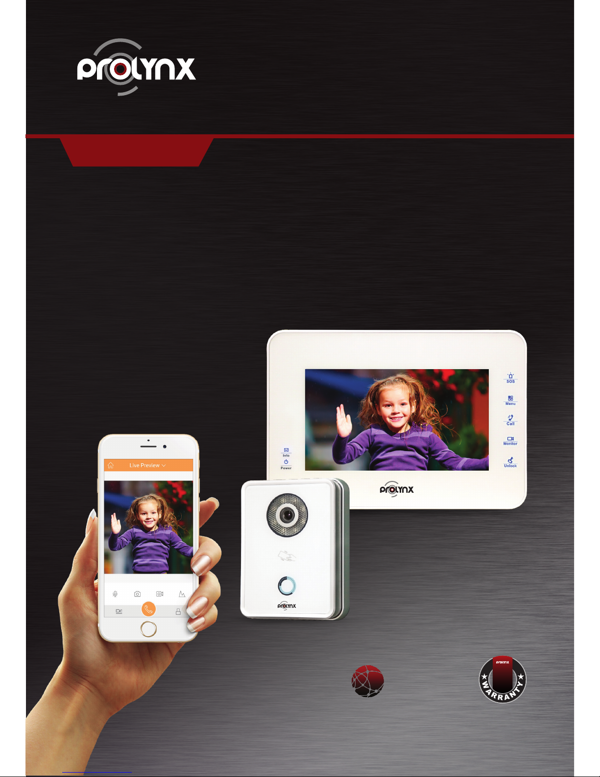
IP VIDEO DOOR PHONE QUICK START GUIDE
7” VIDEO DOOR PHONE SYSTEM WITH SMARTPHONE CONNECT
PL-VDIO-05
W
A
R
R
A
N
T
Y
YEAR
2
P2P
SERVICES
Smartphone Connect
Receive calls, remote monitor and remote unlock
with your smart phone
Page 2
IP VIDEO DOOR PHONE QUICK START GUIDE
Thank you for purchasing our device!
This quick start guide will help you become familiar with our device in a very short time.
Before installation and operation, please read the following safeguard and warning carefully!
CAUTION
FOR YOUR OWN SAFETY, PLEASE CHANGE SYSTEM’S DEFAULT PASSWORD AFTER YOU FIRST LOGIN!
Welcome
1. Electrical safety
All installation and operation here should conform to your local electrical safety codes. The
product must be grounded to reduce the risk of electric shock. We assume no liability or
responsibility for all the fires or electrical shock caused by improper handling or installation.
2.Transportation security
Heavy stress, violent vibration or water splash are not allowed during transportation, storage and
installation.
3.Installation
Keep upwards. Handle with care.
Do not apply power to the device before completing installation.
Do not place objects on the device.
4.Qualified engineers needed
All the examination and repair work should be done by the qualified service engineers.
We are not liable for any problems caused by unauthorized modifications or attempted repair.
5.Environment
The device should be installed in a cool, dry place away from direct sunlight, inflammable,
explosive substances and etc.
6. Accessories
Be sure to use all the accessories recommended by manufacturer.
Before installation, please open the package and check all the components are included:
Contact your local retailer immediately if something is missing in your package.
Important Safeguard and Warning
Page 3
TABLE OF CONTENTS
1 Typical Connection 3
1.1 IP Connection Mode 1 3
2 General Settings 4
2.1 Change Default Password 4
2.2 Outdoor Station Settings 5
2.3 Master Digital Indoor Monitor Settings 6
2.4 Digital Extension Indoor Monitor Settings 7-8
2.5 Change Villa Outdoor Station IP via Indoor Monitor 8-11
2.6 Check Results 11
3 Network Camera Settings 12
3.1 Indoor Monitor Settings 12
3.2 Add Network Camera 12
3.3 Add ONVIF Network Camera 12
3.4 Check Results 13
4 Mobile Phone Settings 14
4.1 Outdoor Station Settings 14
4.2 Mobile Phone Settings 14-16
4.3 Check Results 16
5 Installation 17
5.1 Outdoor Station Installation 17
5.2 Indoor Monitor Installation 18
6 Electric Lock and Magnetic Door Lock 19
6.1 Electric Door Lock 19
6.2 Magnetic Door Lock 19
7 Appendix Specifications 20-21
Page 4
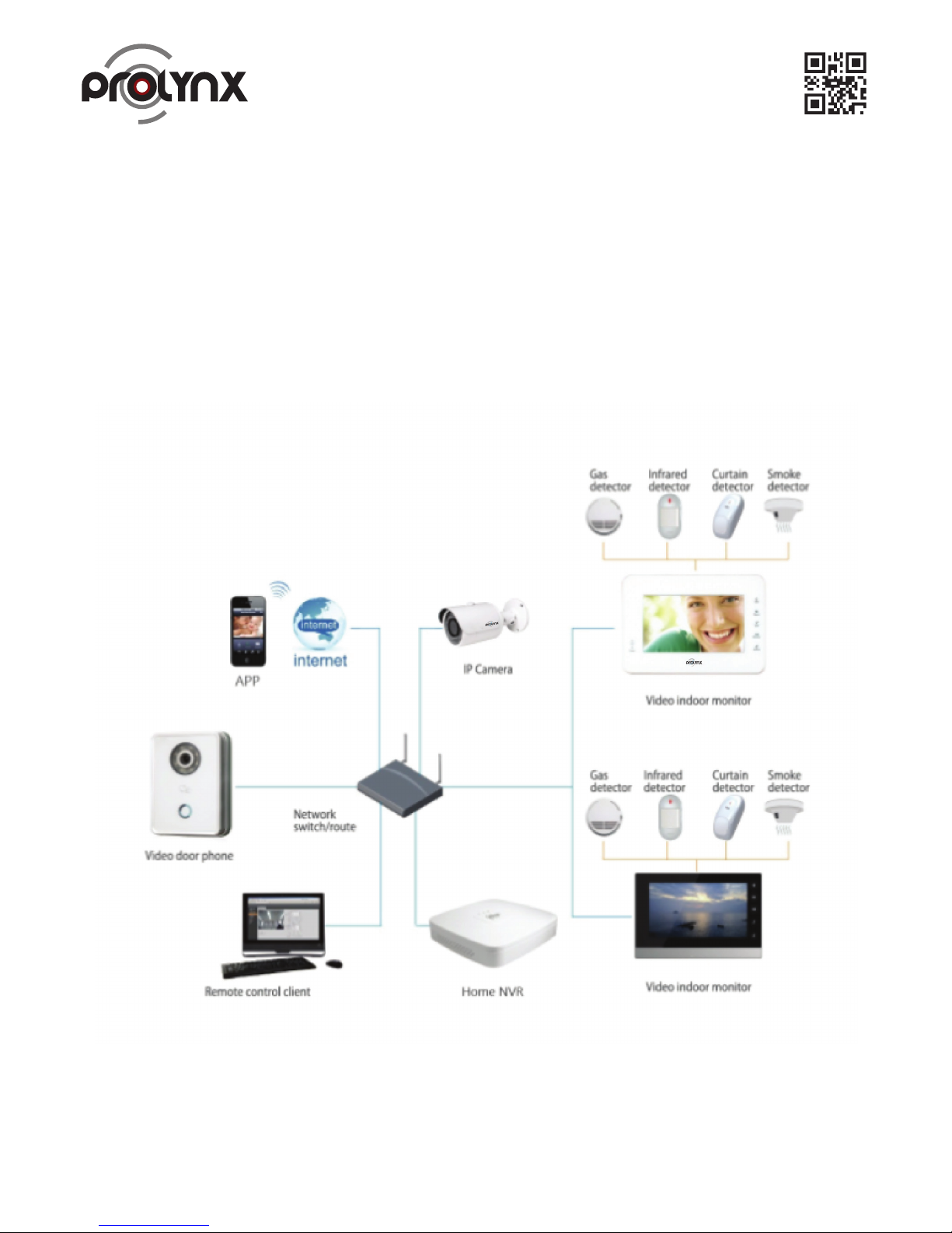
Figure 1- 1.
Note: All the installation and operations here should conform to your local electric safety rules.
When a visitor press call button on Outdoor Station, multiple Indoor Monitors will ring at the same
time. You can call, hang up, and unlock on any of these Indoor Monitors
1. Typical Connection
This mode is for 7”.
Indoor Monitor has one master Indoor Monitor and up to three extension Indoor Monitors. See
Figure 1 1.
1.1 IP Connection Mode 1
3
Page 5
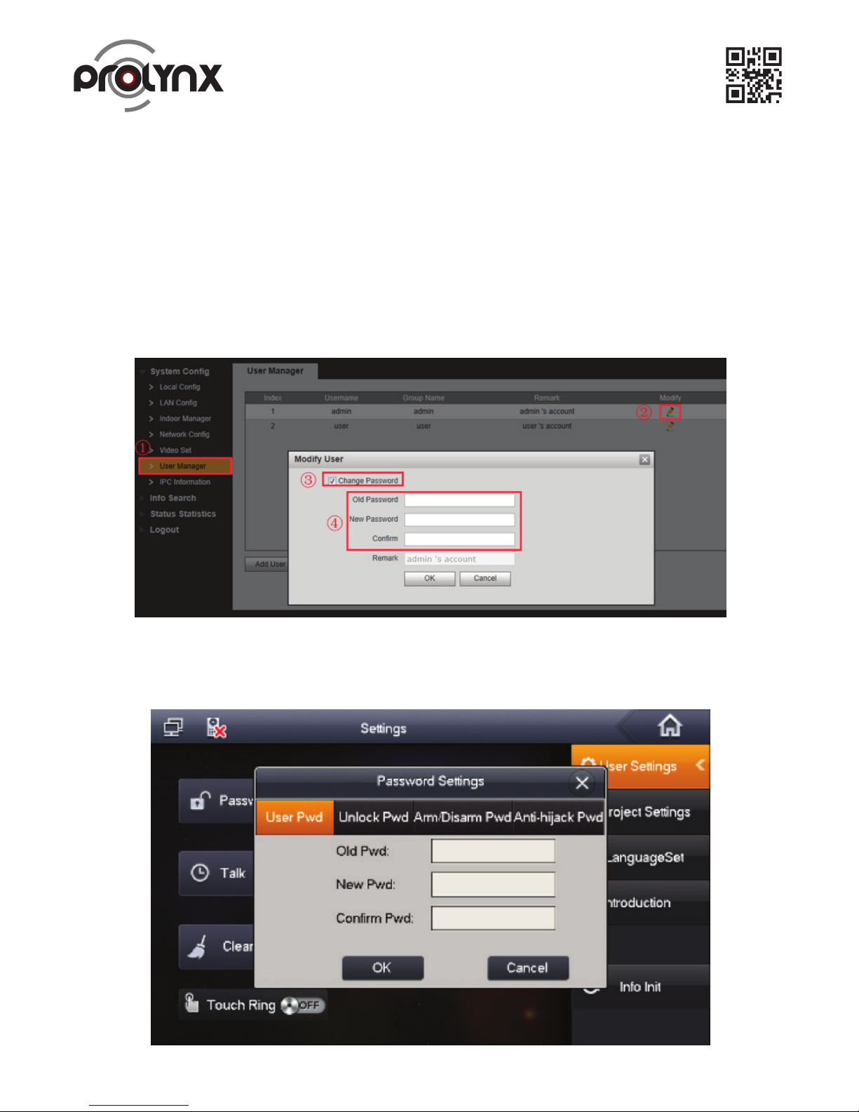
Figure 2- 1.
Figure 2- 2. 4
The Outdoor Station default IP address is 192.168.1.110. The default WEB account is
User name: admin, password: admin.
The Indoor Monitor default IP address is 192.168.1.109, the project password is 002236.
After the connection, please make sure the Indoor Monitor and Outdoor Station connection are OK.
Please change the default password after your first login.
2. General Settings
Please refer to Figure 2 1 to change Outdoor Station password.
Please refer to Figure 2.2 to change account password, open door password, arm/disarm password,
anti-hijack password of the Outdoor Station (Settings->Password).
2.1 Change Default Password
Page 6
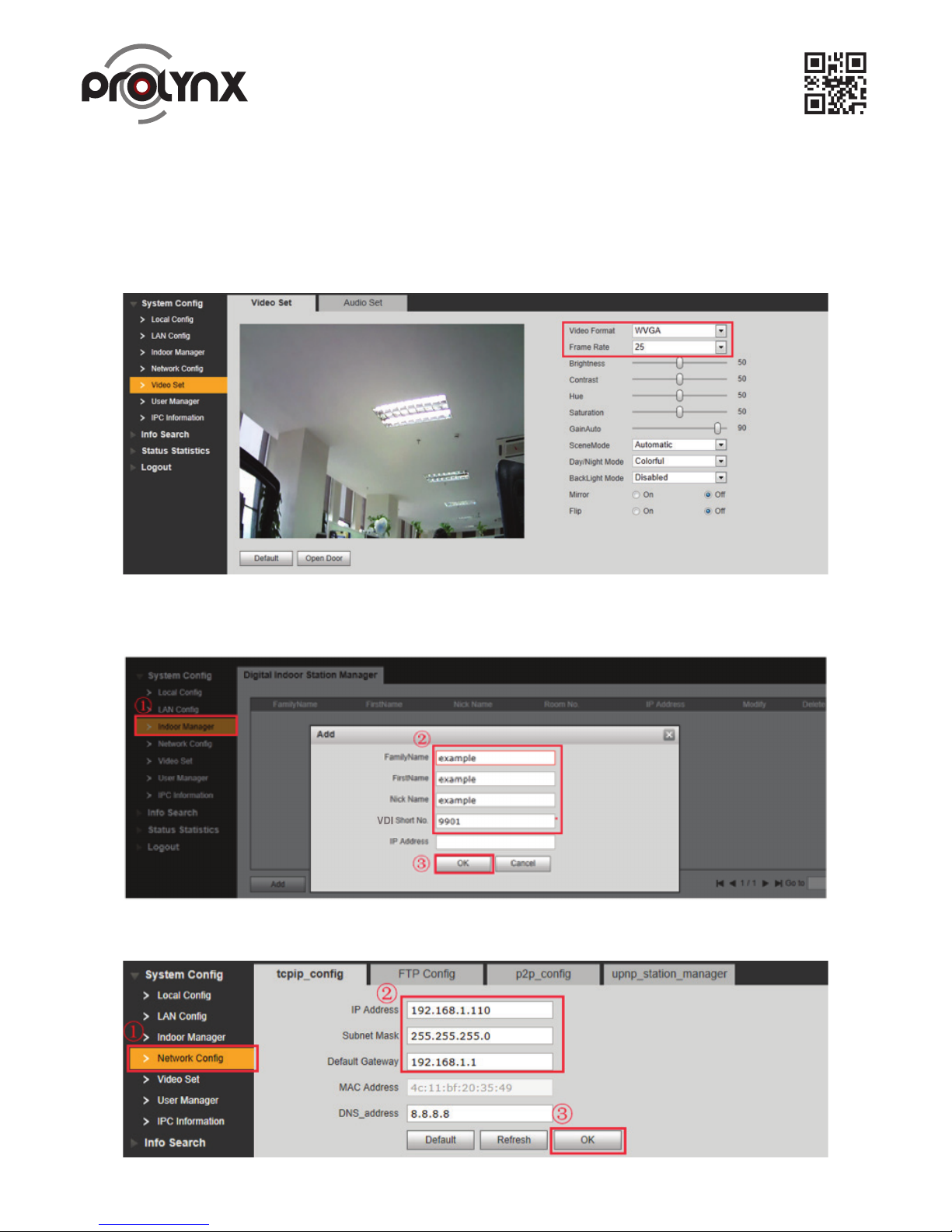
5
Figure 2- 3.
Figure 2- 4.
Figure 2- 5.
a) Please use the PC to access the Outdoor Station. Open the browser and then input the Outdoor
Station IP address. Click the Enter, input user name and password to login.
b) Now you can set local information. See Figure 2-3.
2.2 Outdoor Station Settings
c) Now you can add digital Indoor Monitor. System has added room 9901 by default. See Figure 2-4.
d) Set network information. See Figure 2-5.
Page 7
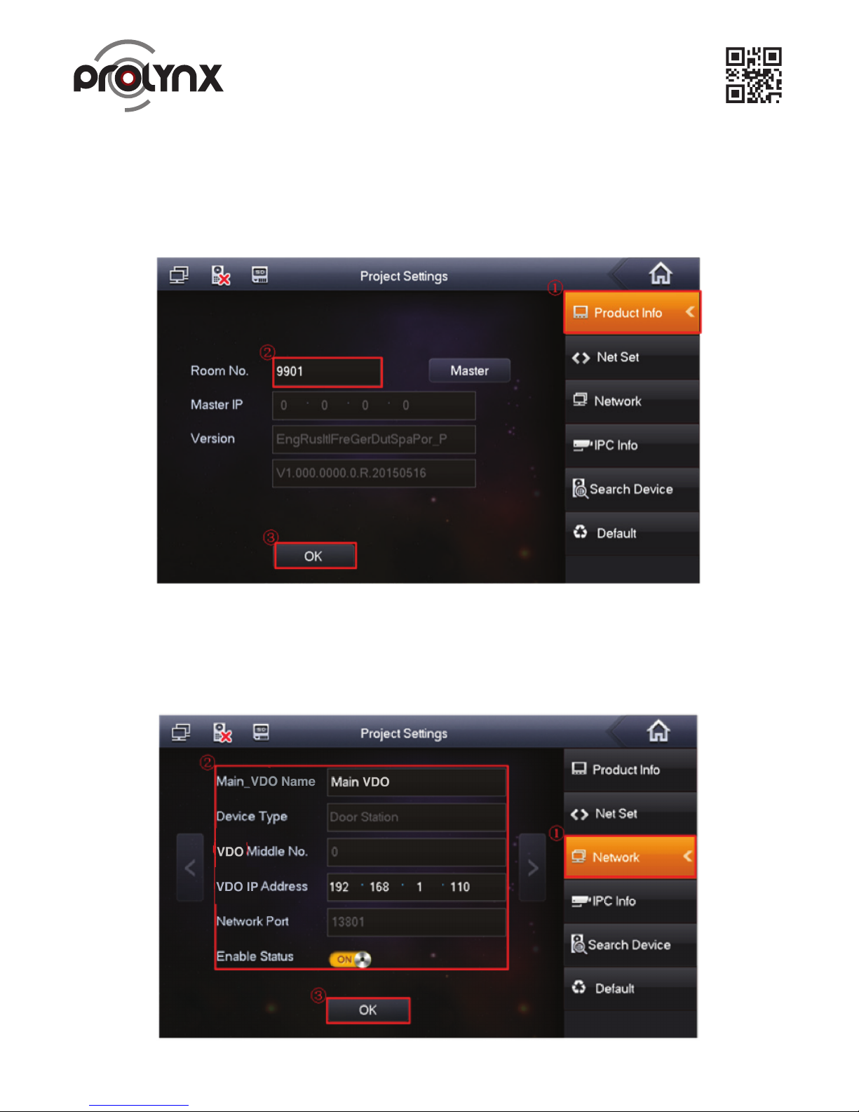
6
Figure 2-7.
Figure 2- 8.
a) On the main Indoor Monitor menu, from System->Project, you can input project password
002236 to go to the project setup interface.
b) Set current Indoor Monitor as the master Indoor Monitor. See Figure 2-7.
2.3 Master Digital Indoor Monitor Settings
c) Click Network on the right pane, and then input master Outdoor Station name, IP address and
enable current function.
Note: Click to go to the extension Outdoor Station interface; you can set extension Outdoor Station
information. You can set several extension Outdoor Stations at the same time. See Figure 2-8.
Page 8
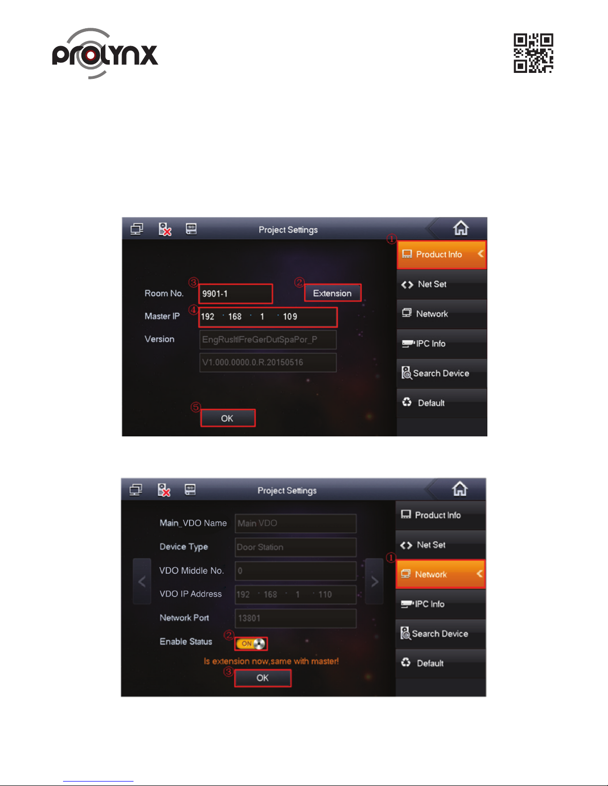
7
Figure 2-9.
Figure 2-10
a) On the extension Indoor Monitor menu, from System->Project, you can input project password
(002236) to go to the project interface.
b) Set current Indoor Monitor as extension Indoor Monitor.
Step1 Press Product Info, See Figure 2-9
Step2 Press Master, Master icon becomes ‘Extension’ icon.
Step3 Set Room No. (i.e. 9901-1), input IP Address, Subnet Mask and Gateway.
Step4 In Master IP, input IP of the master Indoor Monitor.
c) Click Network on the right pane and then enable current function. See Figure 2-10.
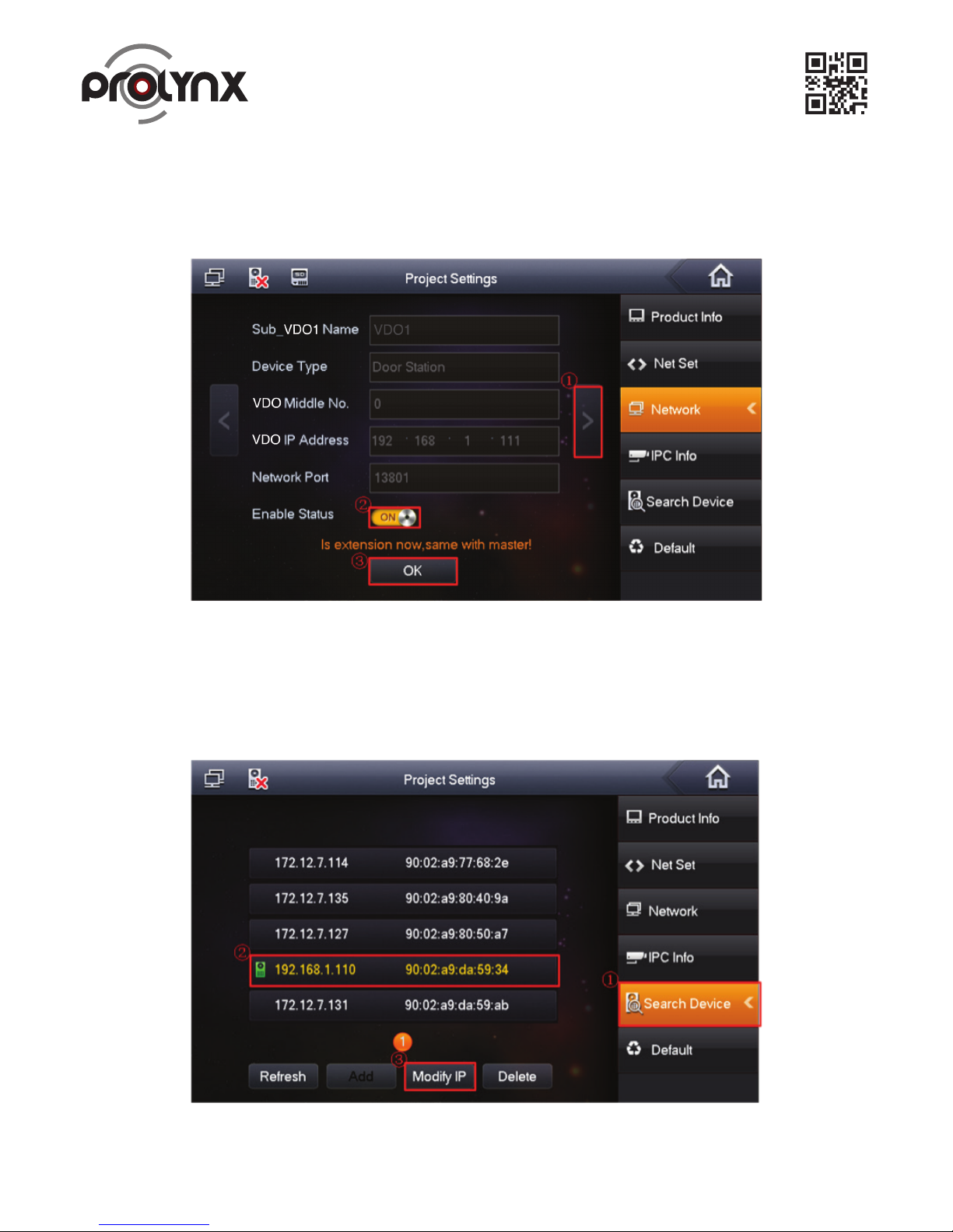
d) Click to go to the next page to set extension Outdoor Station. Enable current function and then click OK.
2.4 Digital Extension Indoor Monitor Settings
Page 9
8
Figure 2-11.
Figure 2-12.
Note
Please make sure the status is ON. The extension Indoor Monitor can synchronize information with
the master Indoor Monitor. If one master Indoor Monitor has several extension Outdoor Stations,
please enable status as on. See Figure 2-11.
a) On the digital Indoor Monitor interface, from Settings->Project->002236, select Search device.
See Figure 2-12.
2.5 Change Villa Outdoor Station IP via Indoor Monitor
Page 10
9
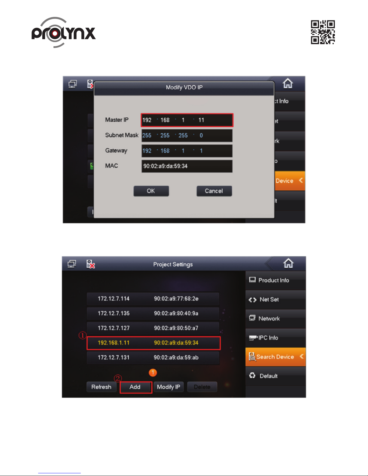
b) Change Outdoor Station IP address as 192.168.1.11. See Figure 2-13.
Figure 2-13.
c) Click Add to add Outdoor Station settings. See Figure 2-14
Figure 2-14.
Page 11
10
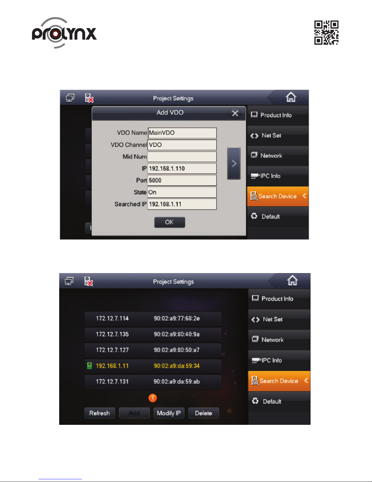
d) Use 192.168.1.11 of the Outdoor Station to change default setup 192.168.1.110, change status
as on. See Figure 2-15.
Figure 2-15.
e) Now you can see the following interface. See Figure 2-16.
Figure 2-16.
Page 12
11
Figure 2-17.
Figure 2-18.
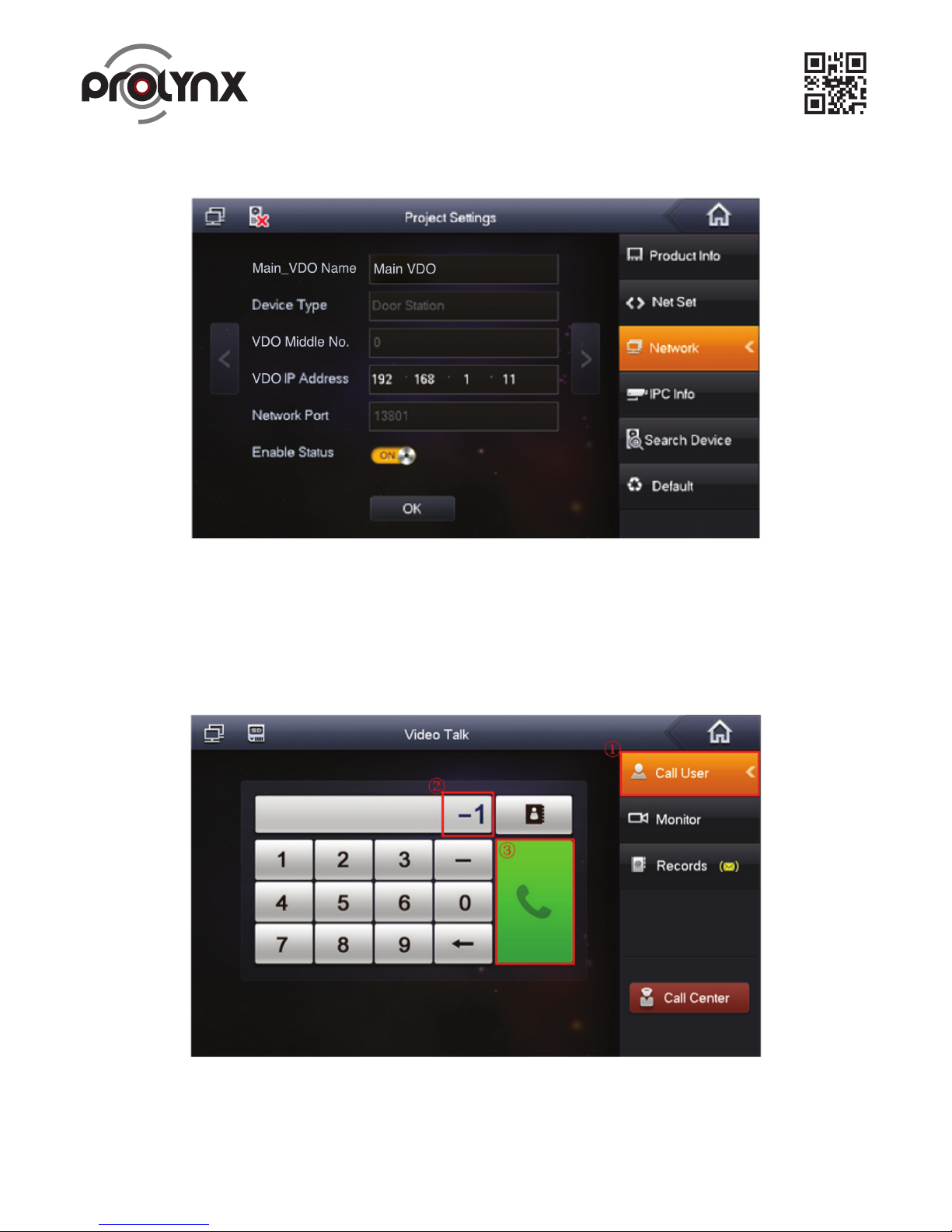
f) Or you can go to the Network interface to view the add result. See Figure 2-17.
• On the indoor Outdoor Station, click monitor button, you can view the situation of the Outdoor Station.
• On the villa Outdoor Station, click the Call button, you can call any of the Indoor Monitors.
• For the Indoor Monitor, from “Video Talk->Call User”, input “-1” to call the Indoor Monitor extension number.
See Figure 2-18.
2.6 Check Results
Page 13
12
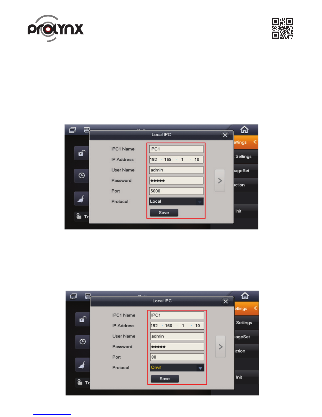
Figure 3-1.
Figure 3-2.
3 Network Camera Settings
The Indoor Monitor supports 8 network cameras. It supports product from Dahua and ONVIF protocol.
3.2 Add VDO Series Network Camera
On the Indoor Monitor menu, from Settings-> Local IPC, input network camera name, IP address,
port (5000), protocol (local) and then click Save button. User name and password are the account
for you to login the network camera. See Figure 3 1.
3.3 Add ONVIF Network Camera
On the Indoor Monitor menu, from Settings-> Local IPC, input network camera name, IP address, port
(80), protocol (ONVIF) and then click Save button. User name and password are the account for you to
login the network camera. See Figure 3 2. On the Indoor Monitor menu, from Settings-> Local IPC, input
network camera name, IP address, port (5000), protocol (local) and then click Save button. User name
and password are the account for you to login the network camera. See Figure 3 1.
3.1 Indoor Monitor Settings
Page 14
13
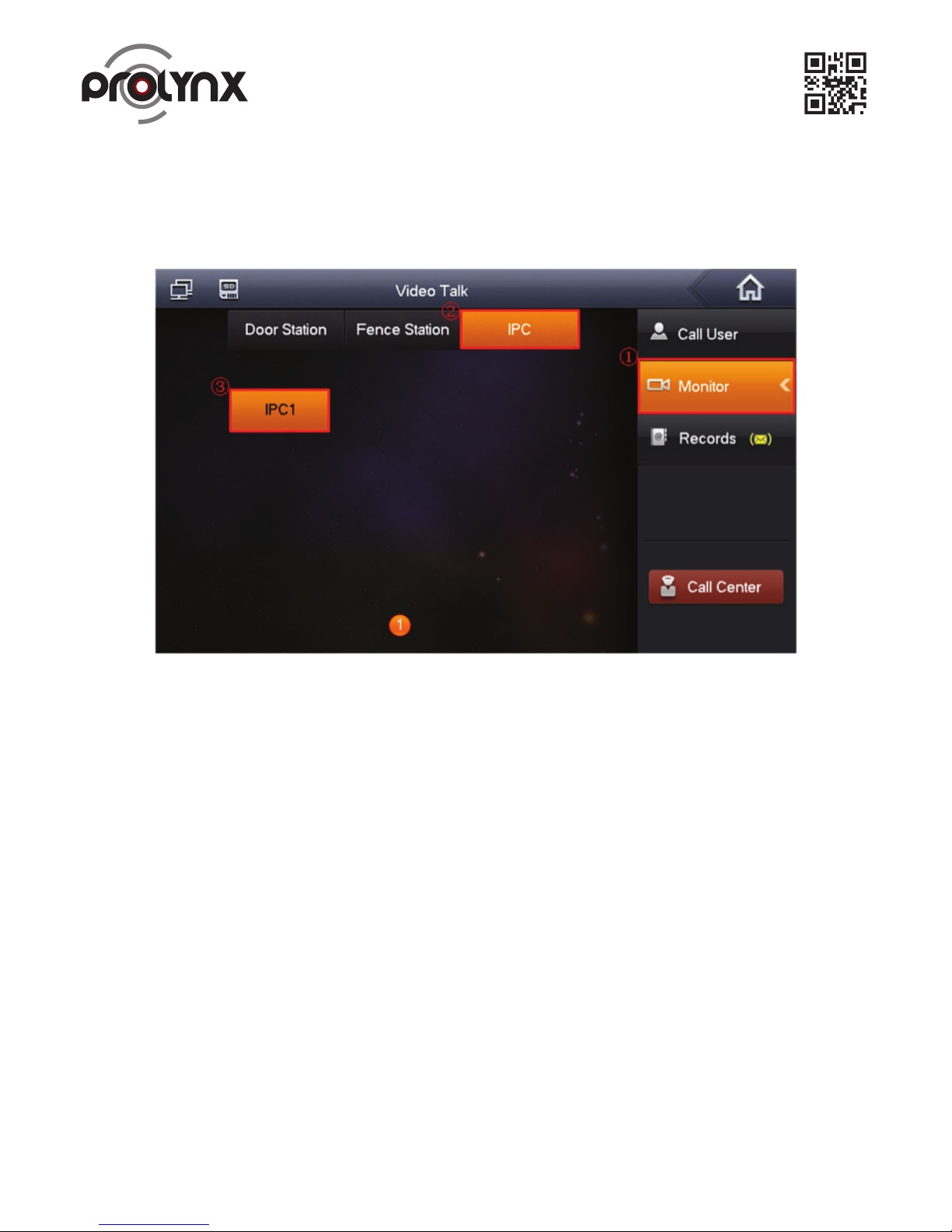
Figure 3-3.
3.4 Check Results
On the Indoor Monitor menu, from Video Talk-> Monitor->IPC, you can use Last Channel/Next Channel
to switch to different network camera video. See Figure 3 3.
Page 15
14
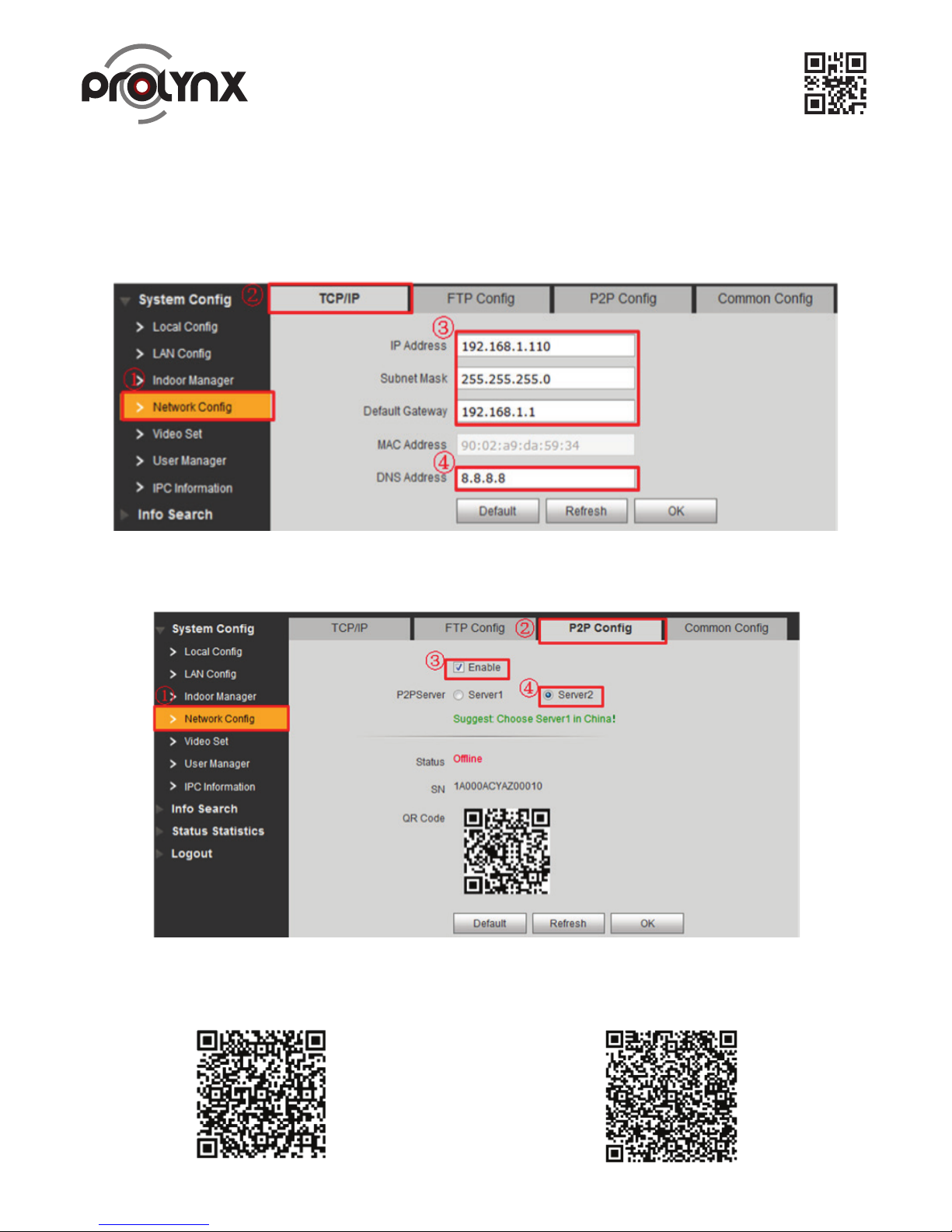
Figure 4-1.
Figure 4-2.
Figure 4-3.
4 Cell Phone Settings
4.1 Outdoor Station Settings
a) Go to the Network interface, set Outdoor Station IP address so that it can connect to the network. Set
local DNS address. See Figure 4 1.
4.2 Cell Phone Settings
a) Scan the QR code to download the APP (mention app name……………….) See Figure 4 3
b) Go to P2P interface; check the box to enable the P2P function. Please wait until the status becomes
on. See Figure 4 2.
APP for Android OS
APP for iPhone OS
Page 16
15
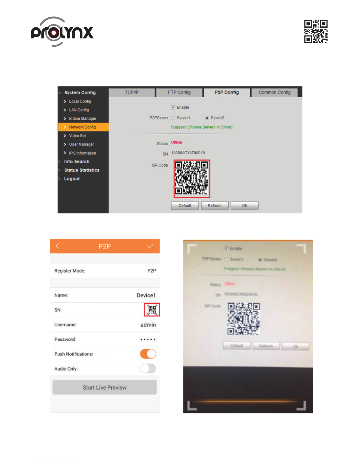
Figure 4-4.
Figure 4-5.
b) Use the cell phone to scan the QR code of Outdoor Station on the device’s label or Web. See Figure 4 4
and Figure 4 5.
Page 17
4.3 Check Results
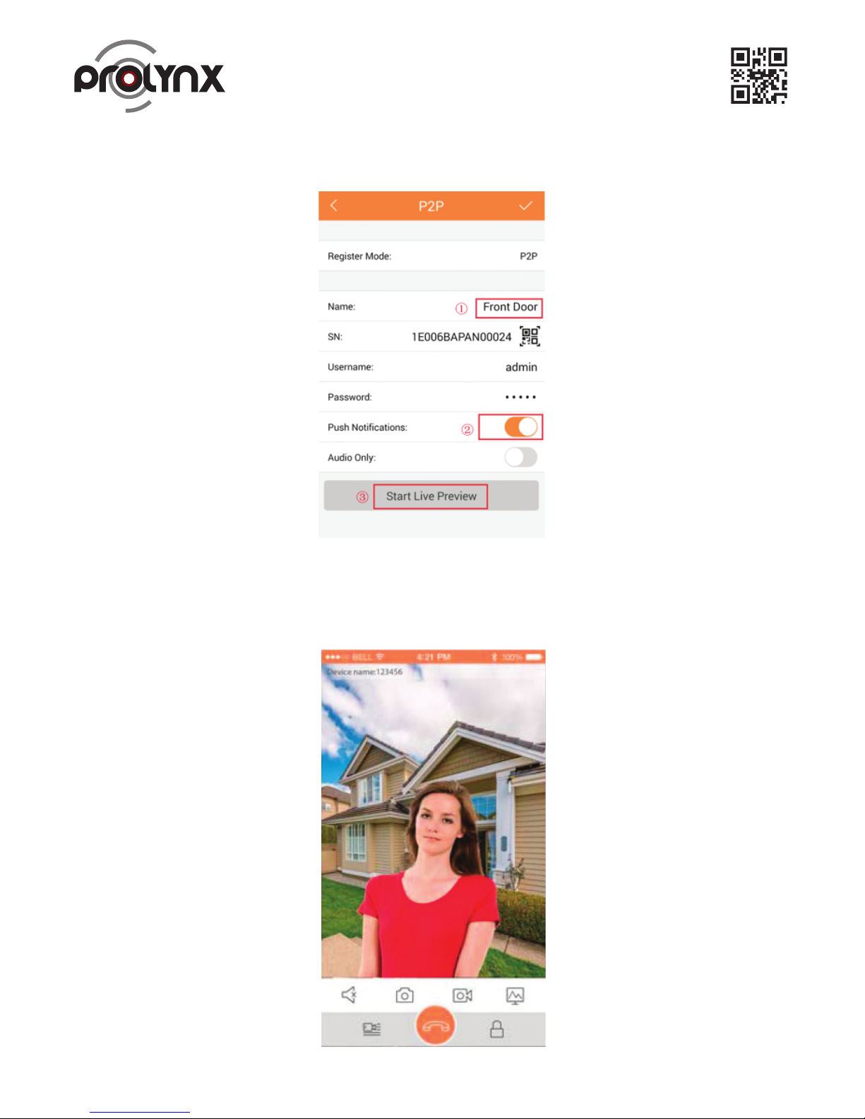
When the Outdoor Station is calling the Indoor Monitor, you can see a push message on your cell phone.
Open the message; you can see the video from the Outdoor Station.
16
Figure 4-6.
Figure 4-7.
c) Give a name to Outdoor Station first. Click the detect Outdoor Station. You can view the corresponding
video from the Outdoor Station after it detects the device. vv
Page 18
5 Installation
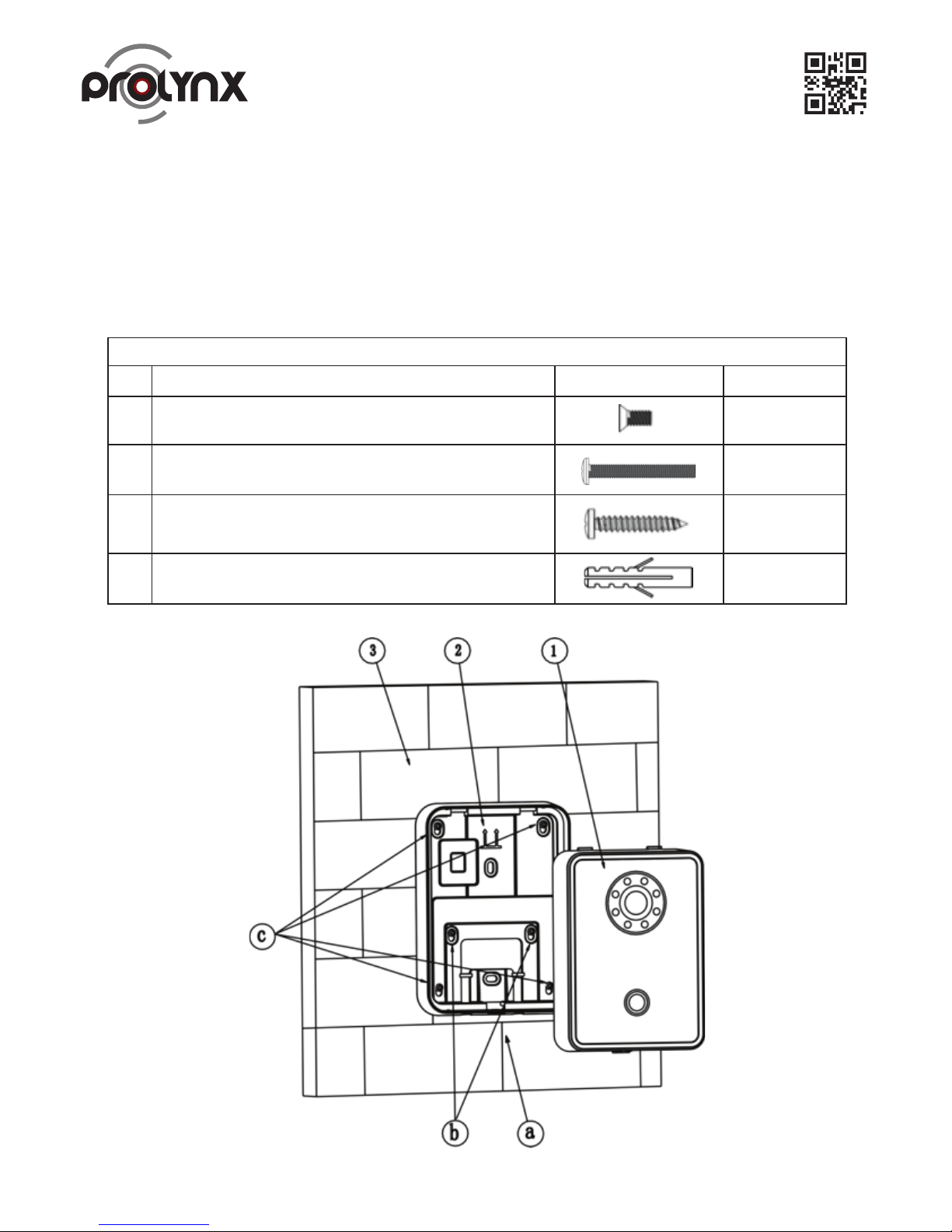
5.1 Outdoor Station Installation
Use screw b to fix bracket onto 86 box embedded/120 box embedded inside ③.
2. Use screw c to fix bracket on ③.
3. Install Outdoor Station ① on Indoor Monitor bracket ②, and fix with screw a.
See Figure 5-1.
17
Figure 5-1.
Screw Illustration
No. Name Illustration Quantity
A
M3×6 Cross recessed countersunk head-black zinc
1
B
M4×30 Cross recessed pan head screws
2
C
ST3×18 Cross recessed pan head tapping screws
–white alloy
4
D
Expansion pipe ¢6*30mm white
4
Page 19
5.2 Indoor Monitor Installation
Important
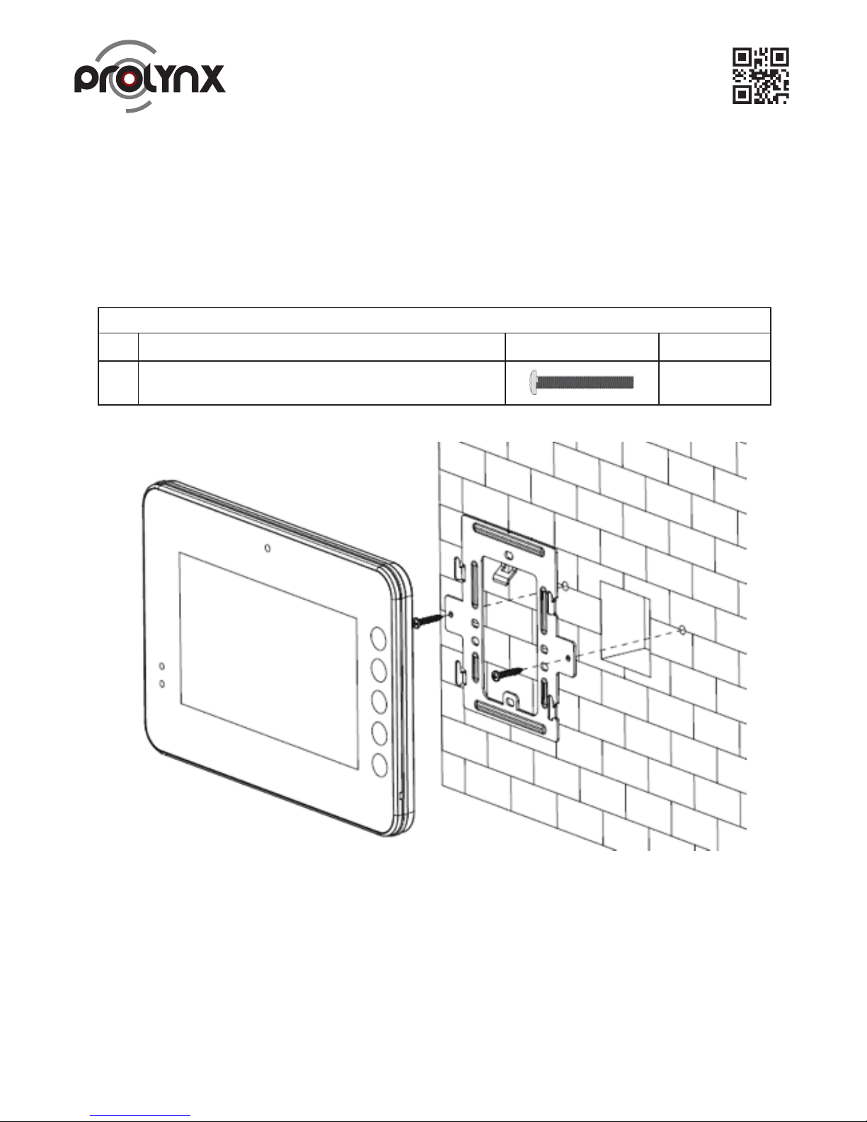
The center of the device shall be 1400mm-1600mm height from the ground.
a) Secure the installation bracket on the wall. Use thirty-two M4×30 screws to fix.
b) Fix the device on the installation bracket and then use the clip to secure. See Figure 5 2.
18
Figure 5-2.
Screw Illustration
No. Name Illustration Quantity
B
M4×30 Cross recessed pan head screws
2
Page 20
19
Figure 6-1.
Figure 6-2.
6 Electric Lock and Magnetic Door Lock
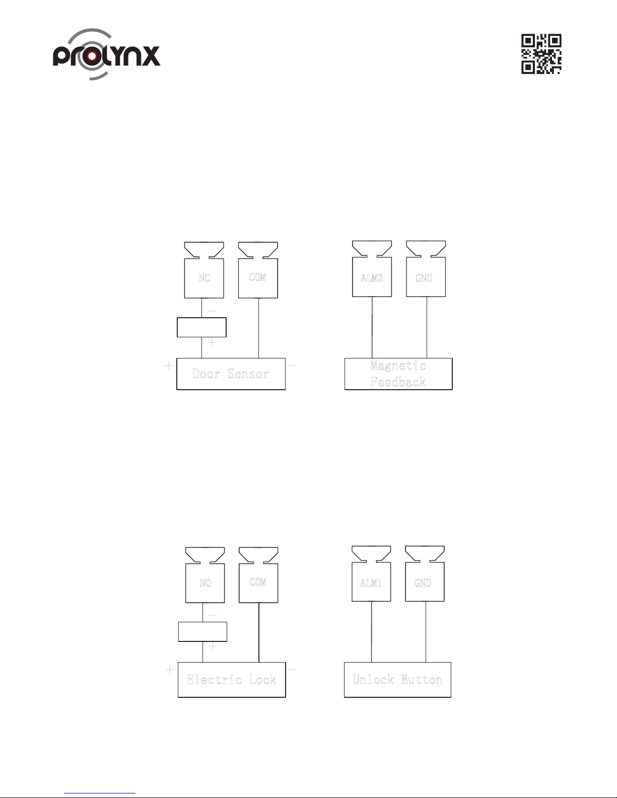
When connect the Outdoor Station to the electric door lock, connect the positive end of the electric
door lock to the NO of the Outdoor Station, connect the negative end of the electric door lock to the
public end.
When connect to the on-off button, connect one end of the on-off button to the one end of the on-off
button of the Outdoor Station, and then connect the other end of the on-off button to the GND of
Outdoor Station. See Figure 6 1.
6.2 Magnetic Door Lock
When connect the Outdoor Station to the magnetic door lock, connect the positive end of the magnetic
door lock to the NC of the Outdoor Station, connect the negative end of the magnetic door lock to the
public end.
When connect to the magnetic door lock feedback, connect one end of the feedback to the one end of
the feedback of the Outdoor Station, and then connect the other end of the feedback to the GND of
Outdoor Station. See Figure 6 2.
6.1 Electric Door Lock
Electric Lock Unlock Button
Power
+ -
GND
ALM1
NO
COM
+
-
Door Sensor
Magnetic
Feedback
Power
+ -
GNDALM2NC
COM
+
-
Page 21
20
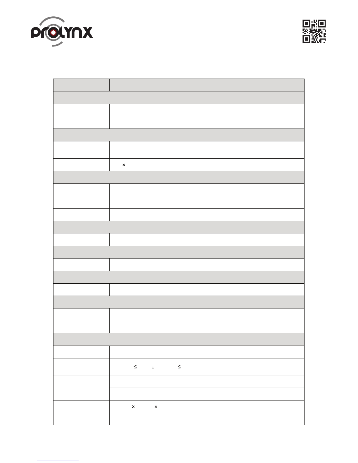
7 Appendix Specifications
Model
Indoor Monitor
OS
Main processor Embedded micro controller
OS Embedded LINUX OS
Video
Video compression
standard
H.264
Resolution 800
480
Audio
Input All-direction microphone
Output Built-in speaker
Audio talk Dual-way bidirectional talk
Display
Monitor dimensions 7-inch TFT true color screen
Operation mode
Input Touch buttons
Alarm
Alarm Input 8-channel local alarm input
Network
Ethernet Network 10M/100Mbps self-adaptive
Network protocol TCP/IP
Specifications
Power DC 10~15V or special switch to provide power directly
Power
consumption
Standby
1.5W working
7W
Working
environment
-10˚C ~ +60˚C
10% ~ 90%RH
Dimensions
(L x W x H )
221mm 154mm 25mm
Weight 0.8kg
Page 22

Note:
• All interface for reference only. Slight difference may be found in user interface.
• All the designs and software here are subject to change without prior written notice.
• All trademarks and registered trademarks mentioned are the properties of their respective owners.
• Please visit our website for more information
21
Model Outdoor station
System
Main Process Embedded micro controller
OS Embedded Linux OS
Video
Video
Compression
Standard
H.264
Input/Sensor Megapixel CMOS HD camera
Night Vision Support
Audio
Input All-direction microphone
Output Built-in speaker
Talk Support bidirectional talk
Operation
Mode
Input Single key input
Door Lock
Status Check
Support (optional)
Network
Ethernet 10M/100Mbps self-adaptive
Network
Protocol
TCP/IP
General
Power
DC 10V ~ 15V or special switch to provide power directly
Consumption Standby 1W; working
10W
Working
Temperature
10˚C ~ +55˚C
Relative
Humidity
10% ~ 90%RH
Dimensions
(L
W
H)
154.2mm 114.2mm
43.0mm
Weight 0.6kg
KANSAS TRADING CO. LLC.
Tel: +971 (4) 222-4464 Fax: +971 (4) 224-3282
P.O. Box: 82769, Dubai, U.A.E. www.kansas.ae [email protected]
 Loading...