

Page 1
Page 2

INTRODUCTION
Thank you for purchasing our products. Combined the latest
technology along with a sturdy mechanical frame, our radios provide
cost-effective communications for the people who need to stay in
touch with the working team such as retail stores, restaurants,
campuses and schools, construction sites, manufacturing, shows
and trade fairs, property and hotel management and more, they are
the perfect communication solutions for all of today’s fast-paced
industries.
We sincerely appreciate your interest on our products, and strongly
suggest you to read the instruction carefully. Your comment will be
highly valued. Please read through the manual in order to get familiar
with the device and learn the features of this model.
Main Features
- PC programmable
- PTT ID / DTMF ANI
- IP55 rating dust and splash protection
- Robust, rugged and heavy-duty design
- Crisp, clear and high quality sound
- 7.4V, 2200mAh high quality Li-ion battery
- Multi-Icon backlit LCD display screen
- FM radio receiver
- 200 programmable channels
- CTCSS tone & DCS code on each channel
- VFO/MR working mode
- Time-out timer
- Squelch level setting
- Built-in VOX
- Battery status indicator
- Squelch tail elimination
- Roger beep tone
Page 3

CONTENTS
01 Chapter 1: SAFETY INFORMATION
01 Radio Care
02 Battery Care
04 Chapter 2: RADIO OVERVIEW
04 Package Includes
04 At a Glance
07 Chapter 3: GETTING STARTED
07 Install and Remove Battery Pack
07 Install and Remove Anetnna
08 Install and Remove Belt Clip
09 AC Adapter and Desktop Charger
09 Charging the Battery Pack
11 Chapter 4: BASIC OPERATION
11 Turn the Radio ON/OFF
11 Adjusting Volume
11 Working Mode
11 Selecting a Channel
11 Frequency Adjust
11 Receiving a Call and Talking
12 LED Indicators
12 LCD Display Screen
13 Save/Delete a Channel
15 Chapter 5: ADVANCED OPERATION
15 Monitor
15 Emergency Calling
15 Scan
15 FM Radio Receiver
16 Default Setting Reset
16 Chapter 6: MENU OPERATION
16 Menu List
17 Detail Function Introduction
17 CTCSS/DCS (C-CDC, R-CDC, T-CDC)
18 TX Power Level (POWER)
18 Transmit Time-out Timer (TOT)
Page 4

18 Squelch Level (SQL)
18 Priority Channel (PRI CH)
19 Scanning Mode (SCANMO)
19 Automatic Power OFF (APO)
19 LCD Backlighting Mode (LIGHT)
19 VOX Sensitivty (VOX)
20 PTT Unit Indentification (PTT ID)
20 Keypad Tone (BEEP)
20 Roger Beep Tone (ROGER)
20 Battery Save (SAVE)
20 Busy Channel Lock-out (BCLO)
20 Squelch Tail Elimination (STE)
21 Offset Frequency and Direction (SHIFTF, SHIFT)
21 Channel Name Editing (CHNAME)
21 Channel Display Mode (DSPMOD)
21 Frequency Step (STEP)
22 Bandwidth (BAND)
22 Dual Watch (DW)
22 Programming Software
23 Chapter 7: TROUBLESHOOTING
25 Chapter 8: SPECIFICATIONS
Page 5

SAFETY INFORMATION
Please read this information before using your radio. Failure to do so
could result in personal injury, death, and/or damage to your radio,
accessories and/or other property.
Radio Care
Advice
● Do not use options or accessories not specified.
● Ensure that the radio is used within the parameters for which it was
designed.
● Turn the radio OFF before connecting optional accessories.
Warning
Turn the radio OFF in the following locations:
● In explosive atmospheres (flammable gas, dust including metallic &
grain powders etc).
● Whilst taking on fuel or while parked near a fuel station.
● Near explosives or blasting sites.
● In aircraft, medical institutions or near persons known to be wearing
a pacemaker.
Caution
● Do not disassemble or modify the radio for any reason.
● Do not transmit while touching the antenna terminal or any exposed
metallic parts of the aerial as this my result in burn.
● Please check and observe regulation in your country with regards to
use whilst driving.
End of Life Disposal
● When your radio reaches the end of its useful life, please ensure that
the unit is disposed of in an environmentally friendly way.
Battery Care
Precautions
● Turn the radio OFF before charging.
● Charge the battery pack before use.
● Do not recharge the battery pack if it is already fully charged
as this
Page 6

will use one its charge cycles and may shorten its life.
● Charge the battery in accordance with the instructions enclosed with
your charger.
● Do not charge the radio and/or battery pack if they are wet.
The battery pack includes potentially hazardous components. Please:
● Do not disassemble or reconstruct battery.
● Do not short-circuit the battery.
● Do not incinerate or apply heat to the battery.
● Do not immerse the battery in water or get it wet by other means.
● Do not charge the battery near fires or under direct sunlight.
● Use only the specified charger and observe charging requirements.
● Do not pierce the battery with any object or strike it with an
instrument.
● Do not use the battery pack if it is damaged in any way.
● Do not reverse-charge or reverse-connect the battery.
● Do not touch a ruptured or leaking battery.
If liquids from the battery get on your skin or into your eyes,
immediately:
● Wash your eyes out with fresh water avoiding rubbing them.
● Seek medical treatment.
Notes:
● If a battery is not to be used for an extended period of time (several
months) remove the battery pack from the equipment and store in a
cool and dry location part charged. Do not fully discharge the battery
before storage.
● Each charge cycle reduces the battery's life. Minimize the number of
times you charge your battery especially in hotter environments which
further shorten a battery's life.
Page 7
RADIO OVERVIEW
Package Includes
1pcs radio unit
1pcs rubber antenna
1pcs rechargeable Lithium-ion battery pack
1pcs AC adapter & rapid desktop charger kit
1pcs belt clip
1pcs user’s manual
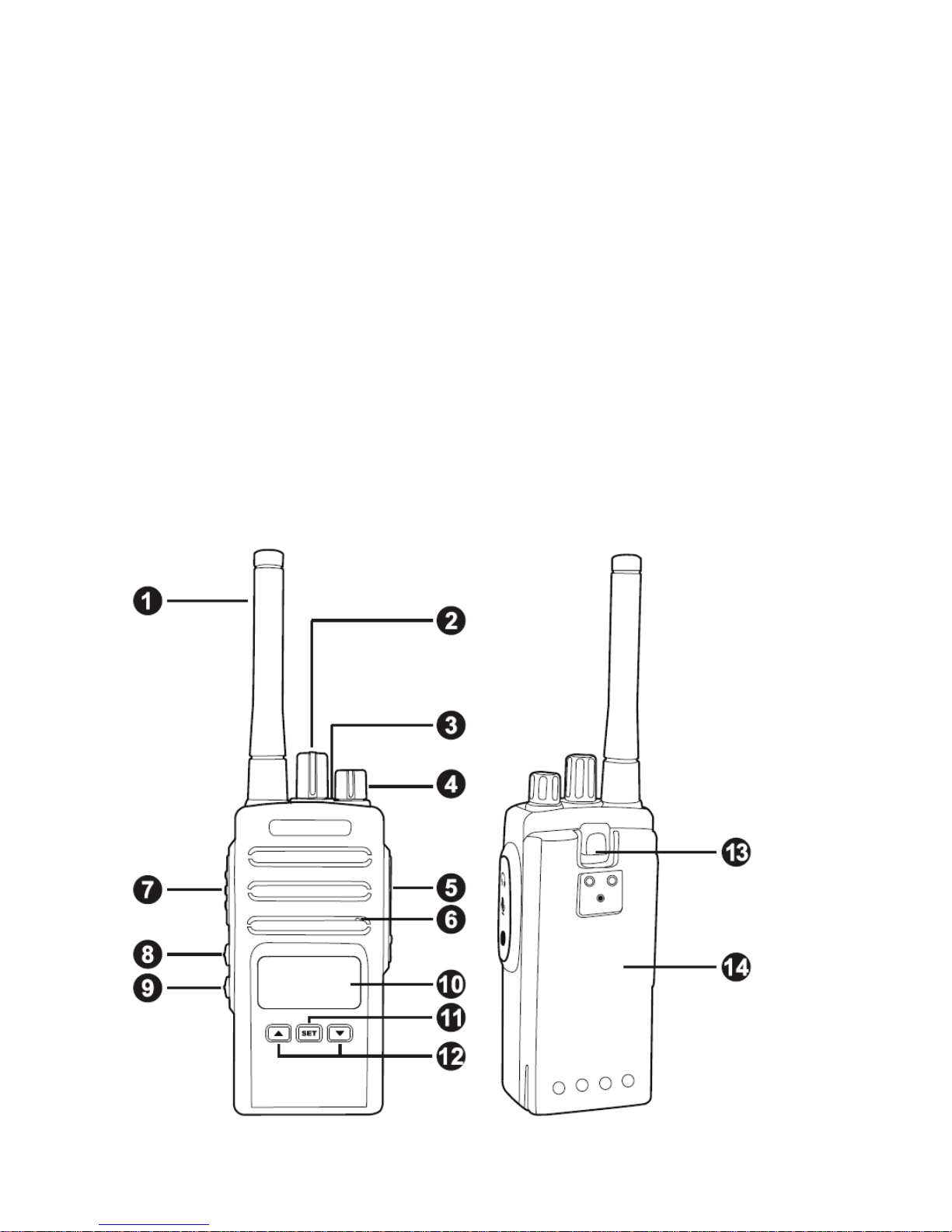
At a Glance
Page 8

1 – Antenna
Provide atWDFKHG60$UXEEHUÀH[LEOHDQWHQQDRUDQWKHUœ
LPSHGDQFHDQWHQQD
1RWH,WPD\FDXVHWKHGDPDJHWR\RXUUDGLRLIWKHDQWHQQDLV
FRQQHFWHGLQDSSURSULDWHO\
2 – Channel Selector Knob
SHOHFWWKHUDGLR¶VGLIIHUHQWIUHTXHQFLHVRUFKDQQHOV
3 – LED Indicator
Give radio battery status, TX & RXVFDQLQIRUPDWLRQ
4 – On/Off/Volume Knob
TXUQWKHUDGLR21RU2)) DQGWRDGMXVWWKHUDGLR¶VYROXPH
5 – Audio Accessory Jack (Motorola 2 Pin Connector)
&RQQHFWFRPSDWLEOHDXGLRDFFHVVRULHV
6 – Microphone
6SHDNFOHDUO\LQWRWKHPLFURSKRQHZKHQWUDQVPLWWLQJ
7 – PTT (Push-To-Talk) Button
3UHVVDQGKROGGRZQWKLVEXWWRQWRWUDQVPLWDQGWDONUHOHDVHLWWR
UHFHLYHDQGOLVWHQ
8 – Side Button P1
Short press tKHEXWWRQP1 is ‘Monitor¶ feature/RQJSUHVVWKHEXWWRQ
P1 is ‘Emergency Calling¶IHDWXUH
Page 9

9 – Side Button P2
Short press the button P2 is ‘Scan’ feature. Long press the button P2
is ‘FM Radio Receiver’ feature. (this feature maybe invalid in some
districts).
10 – LCD display screen
You will see the working channel frequency, name, number and
various icons which stand for the selected functions.
11 – SET Button
Short press this EXWWRQLVWRHQWHUPHQXPRGHRUFRQ¿UPWKHFXUUHQW
operation. Long press the button a few seconds is to lock the side and
front buttons operation. Press and hold this button and turn on the
radio is switch between VFO and Channel mode.
12 – UP/DOWN Navigation Buttons
Press the two buttons to select the desired channels under Channel
mode or menu items when operating in menu mode.
13 – Lithium-Ion Battery Pack
Radio comes equipped with a rechargeable Lithium-ion battery pack.
This battery should be fully charged before initial use to ensure
optimum capacity and performance. Batteries are
designed
specifically to be used with a supplied charger and vice versa.
14 – Battery Latch
Push down battery latch to release battery pack.
Page 10
GETTING STARTED
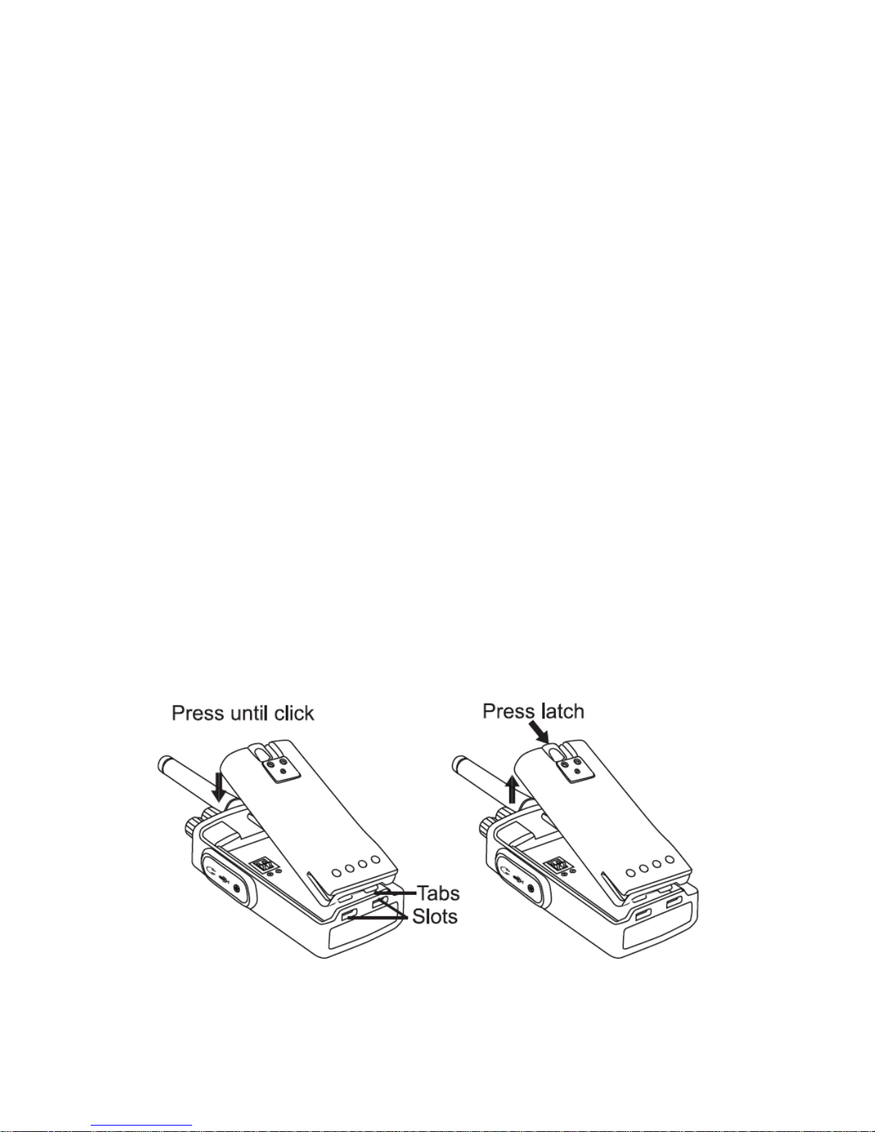
Install and Remove Battery Pack
Installing Battery
1. Turn the radio OFF.
2. With the top side up on the battery pack, fit the tabs at the bottom
of the battery into the slots at the bottom of the radio’s body.
3. Press the top part of the battery towards the radio until a click is
heard.
Removing Battery
1. Turn the radio OFF.
2. Push down the battery latch and hold it while removing the
battery.
3. Pull the battery away from the radio.
Page 11
Install and Remove Antenna
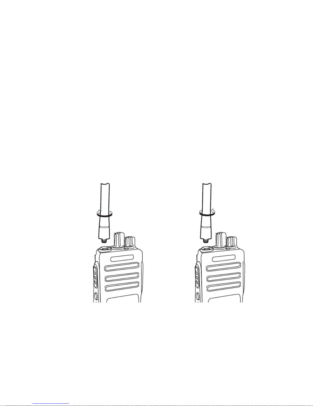
Installing Antenna
Screw the antenna into the connector at the top of the radio by holding
the bottom of the antenna, and turning it clockwise until secure.
Removing Antenna
Rotate the antenna counter clockwise by holding the bottom of
antenna.
Install and Remove Belt Clip
Installing Belt Clip
Page 12
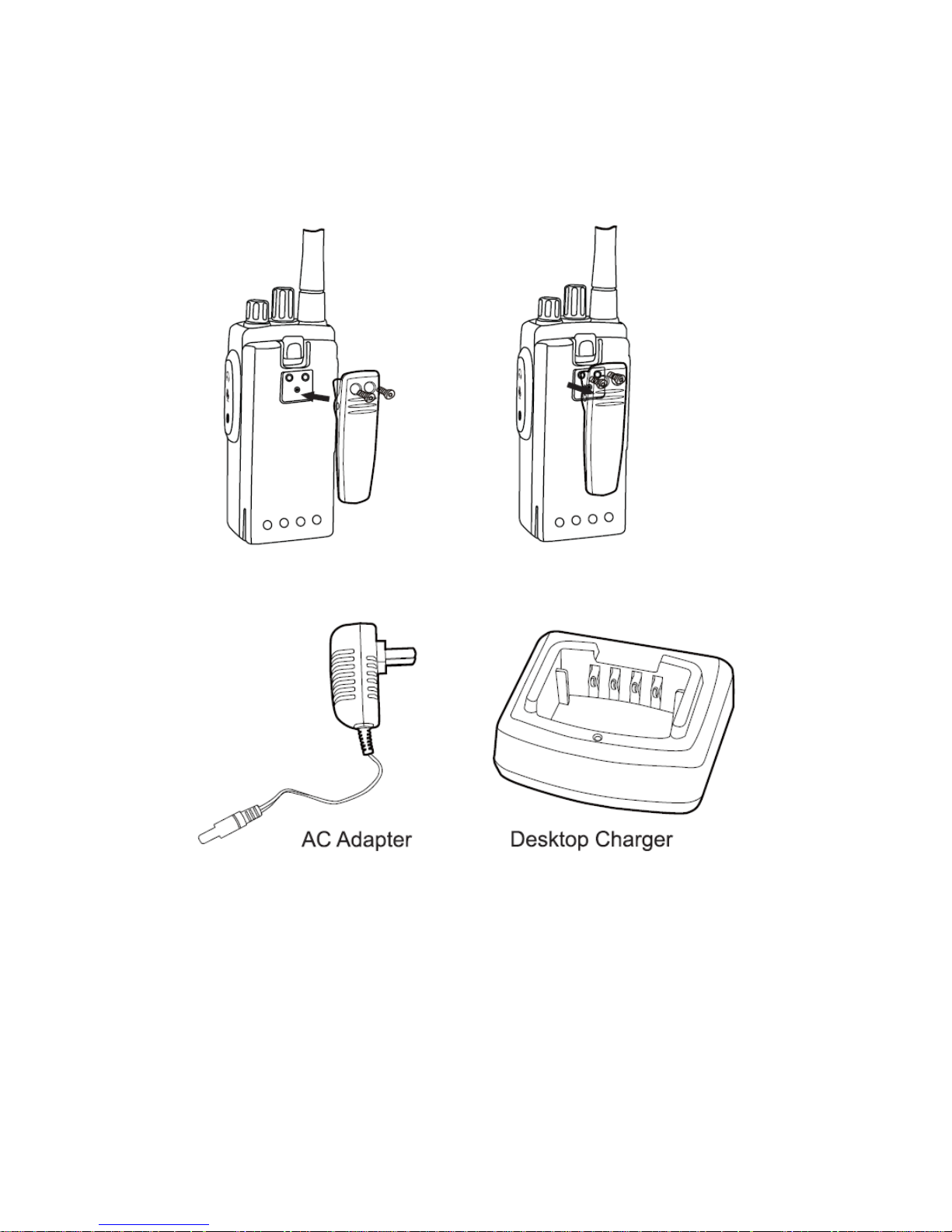
Align the screw eyelets of the belt clip with those on rear of radio and
fasten the belt clip with enclosed screws.
Removing Belt Clip
Loosen the screws to remove the belt clip.
AC Adapter and Desktop Charger
The radio is equipped with 1pcs AC adapter and 1pcs desktop
charger.
Charging the Battery Pack
To charge the battery pack, place it in the supplied desktop charger.
Page 13
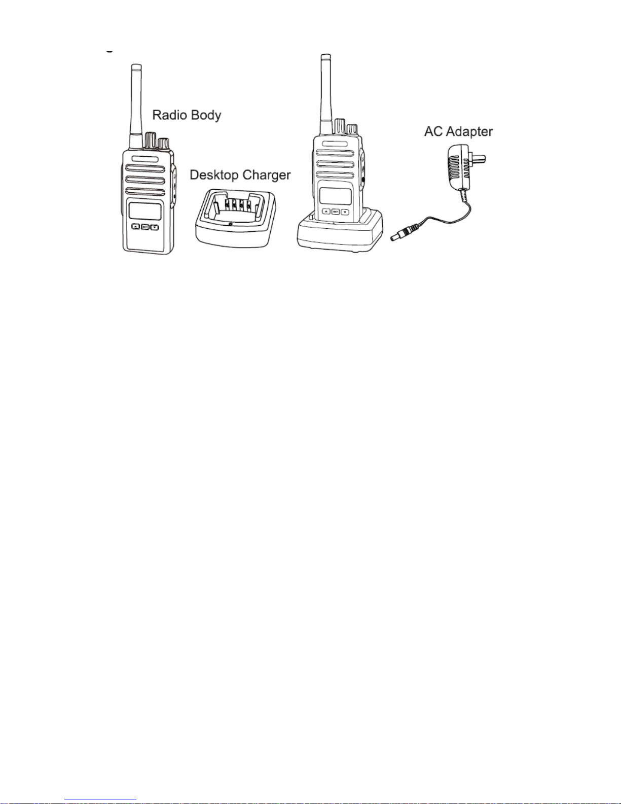
1. Place the desktop charger on a flat surface.
2. Insert the connector of the AC adapter into the charger port on
the back of the desktop charger.
3. Plug the AC adaptor into a power outlet.
4. The charger is ready for charging if the indicator LED lights red
for one second and turns off. If the indicator LED is flashing, the
charger is not ready.
5. Place the battery into the charger aligning the battery slots with
the charger guide rails.
6. The indicator LED lights red when charging. If the battery
capacity is too low, the indicator LED flashes red. The battery first
trickle charges and turns to normal charging automatically.
7. The battery is fully charged when the battery LED light is green.
The charger stops charging automatically.
Notes:
● When you charge a battery attached to the radio, turn the radio OFF
to ensure a full charge.
● The estimated charging time of the battery with charger is about 5
hours.
Page 14

BASIC OPERATION
Turn the Radio ON/OFF
To turn on the radio, rotate on the On/Off/Volume Knob clockwise. The
radio plays power up audio, displays current channel number or
frequency on the screen.
To turn off the radio, rotate the On/Off/Volume Knob counter-clockwise
until you hear a ‘Click’ sound.
Adjusting Volume
Turn the On/Off/Volume Knob clockwise to increase the volume, or
counterclockwise to decrease the volume.
Note: Do not hold the radio too close to the ear when the volume is
high or when adjusting the volume.
Working Mode
The radio has two working modes: VFO and Channel. Press and hold
in [SET] button and turn on the radio to switch between VFO model
and Channel mode.
Selecting a Channel
When the radio is under Channel mode, to select a channel, turn the
Channel Selector Knob until you reach the desired channel. Each
channel has its own frequency, privacy code and other settings.
Frequency Adjust
Under VFO mode, turn the Channel Selector Knob until you reach the
desired frequencies.
Receiving a Call and Talking
1. Select a channel by rotating the Channel Selector Knob until you
reach the desired channel.
Page 15
2. Make sure the PTT button is released and listen for voice activity.
3. The LED indicator stays solid green when the radio is receiving a
call. And the screen will show signal strength.
4. To respond, hold the radio vertically 1 to 2 inches (2.5 to 5 cm)
from mouth. Press the PTT button to talk; release it to listen.
5. When transmitting, the LED indicator stays solid red or yellow.
(Red means high TX power level setting; Yellow means low TX
power level setting)
LED Indicators
Radio Working Status and LED Indicators
Radio Status
LED Indicator
Low Battery
Red Heartbeat
Transmit (TX) in High Power
Solid Red
Transmit (TX) in Low Power
Solid Yellow
Receive (RX)
Solid Green
Scanning
Green Heartbeat
PC Programming/Reading Data
Red Heartbeat
PC Programming/Writing Data
Green Heartbeat
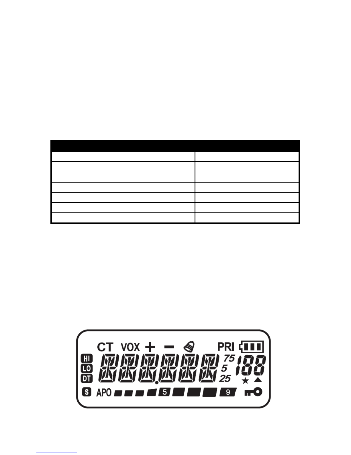
LCD Display Screen
On the display screen, you will see various icons which stand for the
selected functions. Here you will find the icons indicator
as below.
Page 16

ICON
Description
Means current channel sets CTCSS tone.
Means the VOX is activated.
Means positive offset frequency.
Means negative offset frequency.
Means the keypad tone is activated.
Means the priority scanning is activated.
Means battery power indicator.
Means channel frequency or menu item.
Means channel number or menu number.
Means current channel is enable scanning.
Means current channel is priority channel.
Means auto power off is activated.
Means real time display receiving signal
strength or power indicator.
Means keypad lockout.
Means current channel sets high power.
Means current channel sets low power.
Means current channel sets DCS code.
Means battery save is activated.
Save/Delete a Channel
1. Select the desired frequency, while operating in the VFO mode.
Be sure to set up any desired CTCSS tone or DCS code, as well
as any desired repeater offset. The power level may also be set
at this time, if you wish to store it.
2. Press and hold [
] button for 2 seconds, and then the left top of
the LCD displays ‘F’ icon.
3. Press [
] or [ ] button to select the channel number you desire
to store (from 1 to 199).
Page 17

4. Press [SET] button to confirm and store the frequency into
memory, and you will operate in the Channel mode.
5. Turn off the radio, press and hold [SET] button and turn on the
radio, the radio will switch back VFO mode. So you may now
enter other frequencies, and store them into additional memory
channels, by repeating the above process.
6. Under Channel mode, turn off the radio, press and hold [
]
button and turn on the radio, ‘DEL?’ will be displayed. Press [
]
or [
] button to select the channel number you wish to delete,
press [SET] button twice to confirm. If you want to cancel, press
P1 or P2 button to exit.
ADVANCED OPERATON
Monitor
This feature enables you to set squelch off and hear the calls with
weak signal. Short press the side button P1 to activate.
Emergency Calling
This feature allows you to send an emergency alert to other users on
the same channel. Other radios on the same channel will sound an
emergency alert after received emergency signal. Long press the side
button P1 to activate, press PTT button to disable it.
Scan
Scan allows you to hear conversations on all channels. When the
radio detects a transmission, it stops scanning and goes to the active
channel. This allows you to listen and talk to people in that channel
without having to channel manually. If there are transmissions on
another channel, you will not hear that activity once the radio has
stopped scanning. Short press the side button P2 to activate.
FM Radio Receiver
This radio comes with the FM radio function.
Long press side button P2 a few seconds to enter FM radio mode. To
select your favorite radio frequency to listen directly, turn the Channel
Selector Knob. Short press [SET] button to switch to FM radio Channel
mode (if you have stored FM radio stations in the programming
Page 18
software).To exit the FM radio mode, long press side button P2 a few
seconds again.
Note: This feature may be invalid in some countries for local radio
laws.
Default Setting Reset
Press and hold [ ] button and turn on the radio. The display will show
‘RESET?’. Press [SET] button once, the LCD will show ‘VFO?’. Press
[SET] button again to confirm and all the setting of VFO mode will be
deleted.
If you choose to ‘FULL?’, all settings under Channel and VFO mode
will be deleted.
MENU OPERATON
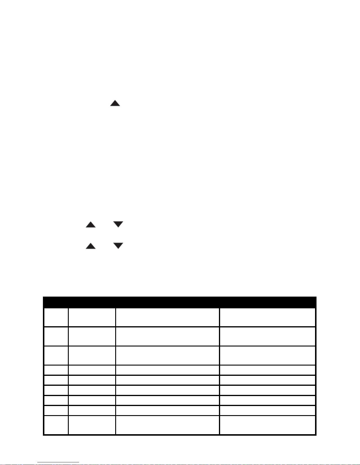
The general steps of menu operation are as follows:
a) Press [SET] button to enter the menu mode;
b) Press [
] or [ ] button to select the desired item;
c) Press [SET] button to enter the sub item;
d) Press [
] or [ ] button to select the desired setting;
e) Press [SET] button to confirm;
f) Press PTT button to return back to the standby screen.
Menu List
No.
Display
Instruction
Setting Contents
1 C-CDC RX & TX CTCSS/DCS
OFF-254.1/D023-D754
N/I
2 R-CDC RX CTCSS/DCS
OFF-254.1/D023-D754
N/I
3 T-CDC TX CTCSS/DCS
OFF-254.1/D023-D754
N/I
4
POWER
TX power level
HIGH/LOW
5
TOT
Time-out timer
OFF/60S/120S/180S
6
SQL
Squelch level
0~9
7
PRI CH
Priority channel
CH-001~CH199
8
SCANMO
Scanning mode
NORMAL/PRI
9 APO Automatic power off
OFF/10M/20M/30M/1H/
2H/3H
Page 19
10
LIGHT
LCD backlighting mode
OFF/AUTO/ON
11
VOX
VOX sensitivity
OFF/LOW/MID/HIGH
12
PTT ID
PTT unit identification
OFF/ON
13
BEEP
Keypad tone
OFF/ON
14
ROGER
Roger beep tone
OFF/ON
15
SAVE
Battery save
OFF/ON
16
BCLO
Busy channel lock-out
OFF/ON
17
STE
Squelch tail elimination
OFF/ON
18
SHIFTF
Offset frequency
0.000~80.000
19
SHIFT
Offset frequency direction
OFF/+/-
20
CHNAME
Edit channel name
------
21
DSPMOD
Channel display mode
FREQ/CH/NAME
22 STEP Frequency step
2.5/5/6.25/10/12.5/25/5
0/100
23
BAND
Channel bandwidth
WIDE/NARROW
24
DW
Dual watch
OFF/ON
Detail Function Introduction
01/02/03 – CTCSS/DCS (C-CDC, R-CDC, T-CDC)
CTCSS and DCS are functions that reject undesired signals on your
channel. You will hear a call only when you receive a signal that
contains a matching CTCSS tone or DCS code. If a call containing a
different tone or code is received, squelch will not open and you will
not hear the call. Likewise, when transmitting using CTCSS or DCS,
the receiving station must have a matching tone or code to hear your
call. Be aware that other parties can still hear your calls if they set up
their radio with the same tone or code. It selects a CTCSS/DCS
privacy code to be used when transmitting or receiving carrier for the
current channel. No privacy code will be checked when carrier is
received if “No CTCSS/DCS code” is chosen.
Procedure:
1) Press [SET] button to enter menu mode, then select No.1 ‘C-CDC’,
No.2 ‘R-CDC’ or No.3 ‘T-CDC’ item.
2) Press side button P1 to select among OFF, CTCSS and DCS.
OFF: No CTCSS/DCS code
CTCSS: 67.0 – 254.1Hz.
DCS: D023 – D754 N/I
3) Press side button P2 to select DCS code phase between normal
and inverted.
Page 20

04 - TX Power Level (POWER)
Allows the user to select TX power level in which the radio will operate
on the current channel. Selecting ‘LOW’ can extend the radio’s battery
life.
LOW: the value is 1 Watt. Used when communication in close
proximity, and to keep the radio from transmitting into other
geographical groups operating on the same frequency.
HIGH: The value is 4/5 Watts. Used when a stronger signal is needed
to extend transmission distance.
Note: this item will be invalid in PMR version.
05 - Transmit Time-out Timer (TOT)
The Time-out Timer prevents callers from using a channel for an
extended duration. If you continuously transmit for the duration
programmed (default is 60s), transmission will automatically stop and
an alert tone will sound. To stop the tone, release the PTT button.
06 - Squelch Level (SQL)
A squelch eliminates background noise. Higher level settings will keep
the squelch ‘closed’ more tightly for quieter monitoring, but weak
signals will not be heard. Lower settings allow weaker signals to ‘open’
the squelch but noise may also cause it to open. The radio has 10
(0~9) squelch levels:
0 – Squelch turns off (monitor on condition)
1 – Maximum sensitivity (minimum squelch)
9 – Minimum sensitivity (maximum/tight squelch)
07 – Priority Channel (PRI CH)
Set the priority channel from all the memory channels. This channel
will be detected always when priority scanning is activated.
08 – Scanning Mode (SCANMO)
There are two scanning modes: normal and priority.
Normal: while in normal mode, short press P2 side button to activate
the channel/frequency scanning function. The radio will automatically
scan from current channel through all the channels until an active
channel is detected, the radio will stop scanning for 5 seconds.
Priority: when priority channel is pre-set through Menu 07 or
Page 21
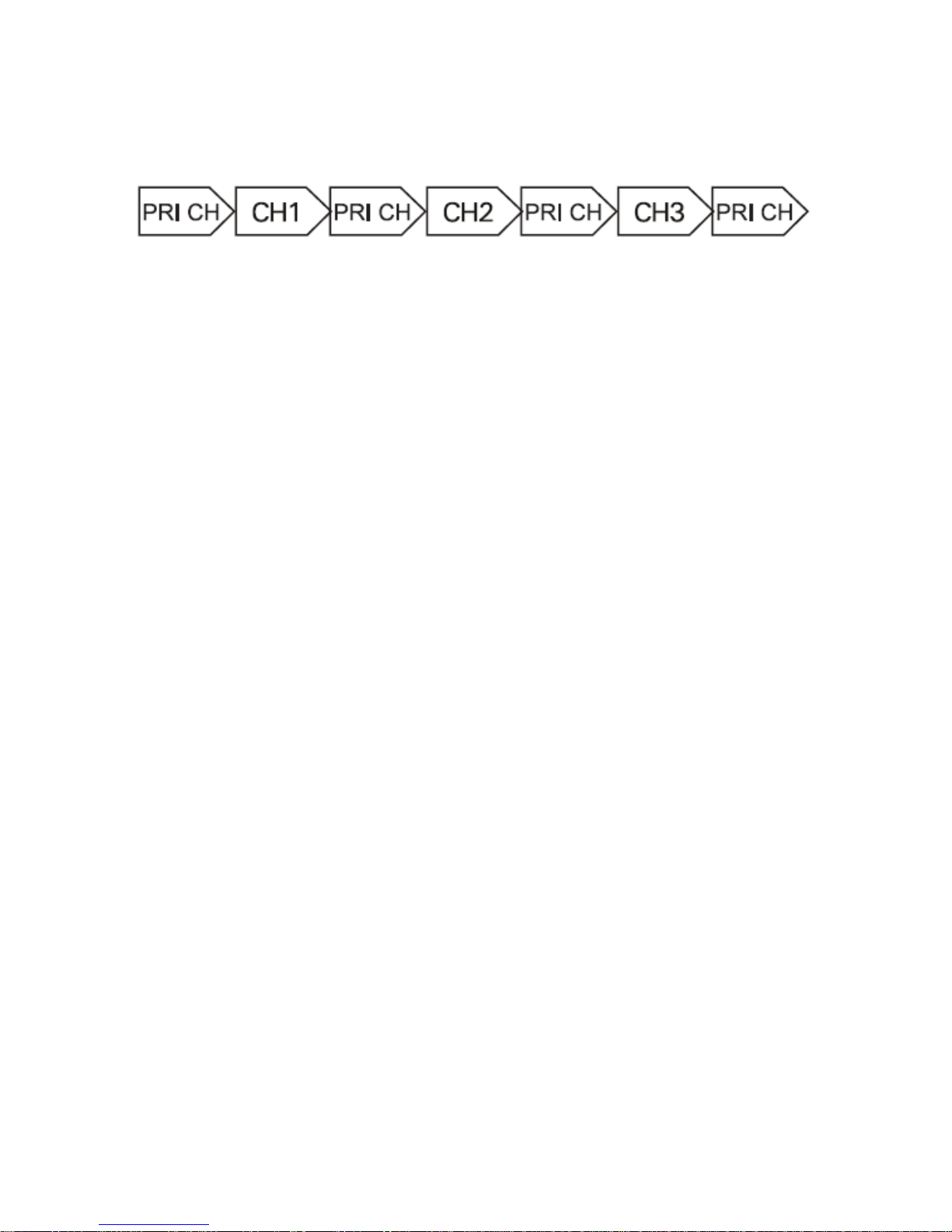
programming software, you can activate priority scanning. Right now
the icon ‘PRI’ will display on the screen. And the radio will start
scanning from the priority channel first and then scans the other
channels. The scanning sequence is:
09 – Automatic Power OFF (APO)
There are OFF/10MIN/20MIN/30MIN/1H/2H/3H for selection. While
one of them is selected, the radio will automatically turn the power off
when times out if none of the button is operated.
The LCD screen shows ‘APO’ icon when this feature is activated.
10 – LCD Backlighting Mode (LIGHT)
There are OFF/AUTO/ON 3 options.
OFF: the backlight is always turned off.
AUTO: after enabling the backlight, it lights for a while before quench
automatically.
ON: the backlight is always turned on.
11 – VOX Sensitivity (VOX)
VOX is a speech control giving the possibility to transmit without using
the radio PTT. The VOX sensitivity can be set in OFF and
LOW/MID/HIGH 3 levels.
LOW stands for the lowest sensitivity; HIGH stands for the highest.
12 – PTT Unit Identification (PTT ID)
A programmed tone sequence is used to control e.g. relays,
repeater…
13 – Keypad Tone (BEEP)
If you enable this function, every time a button is pressed, you will hear
a beep tone.
14 – Roger Beep Tone (ROGER)
When the PTT button is released, the radio will beep to confirm to
other users that you’ve finished your transmission and that they can
start talking.
15 - Battery Save (SAVE)
Page 22

When it is activated, the radio decreases the amount of power used
after no signal is present and no operations are being performed for 5
seconds. When a signal is received or an operation is performed, this
feature turns off temporarily.
16 - Busy Channel Lock-out (BCLO)
It prevents the radio’s transmitter from being activated if a signal
strong enough to break through the ‘noise’ squelch is present. It
prevents users from disrupting others’ talking who are transmitting on
the same channel frequency.
17 – Squelch Tail Elimination (STE)
A burst of noise (squelch tail) heard after a transmission ends. When
STE is activated, the radio will send a sub-audible tone to be
transmitted at the end of a transmission which cause the receiving
radio to mute its speaker before loss of a carrier is detected. Muting
the speaker eliminates unwanted noise during loss of carrier detection.
18/19 – Offset Frequency and Direction (SHIFTF,
SHIFT)
These two items are used to determine the difference between TX and
RX frequency.
The offset frequency range is 00.000-80.000MHz.
Note: this function can only be enabled in VFO mode.
20 – Channel Name Editing (CHNAME)
When you operate in Channel mode, you can edit the current channel
name here.
Procedure:
1) Press [SET] button to enter menu mode, then select No.20
‘CHNAME’ item.
2) Rotate Selector Knob to edit 1
st
position content.
3) Press [
] button to move forward to next position. Then repeat
last step.
4) Press [
] button to move backward to previous position and
modify content if necessary.
5) When finish 6 positions editing, press [SET] button to confirm
and exit.
Note: this function can only be enabled in Channel mode.
Page 23

21 – Channel Display Mode (DSPMOD)
There are 3 display modes as channel frequency + number, channel
number and channel name in total for option.
FREQ: Frequency + Channel number display. Press and hold in [SET]
button and turn on the radio to switch into VFO mode.
CH: Channel number display.
NAME: Channel name display. When a channel is not named, LCD
displays its channel number instead.
Note: this function can only be enabled in Channel mode.
22 – Frequency Step (STEP)
There are 2.5/5/6.25/10/12.5/25/50/100KHz 8 step options.
Note: This function can only be enabled in VFO mode.
23 – Bandwidth (BAND)
Select the transmitter deviation while operating on the current channel.
W: Max. Deviation = ± 5 KHz
N: Max. Deviation = ± 2.5 KHz
24 – Dual Watch (DW)
When dual watch feature is set as on, the radio will enable to monitor
current frequency or channel signal even the FM radio mode is
activated.
Programming Software
The easiest way to program or change features in your radio is via its
programming software and programming cable. The programming
software is available for free as downloadable software at our website.
To program, connect the radio with your PC via the programming cable,
as shown picture as below.
Page 24

The programming software allows you to program the frequencies,
CTCSS/DCS privacy codes as well as other features such as: TX
power, bandwidth, VOX, battery save, TOT, working mode, roger beep,
busy channel lock-out…etc.
More features programmed via the programming software, please
refer to our programming guide.
TROUBLESHOOTING
Problem
Possible Reasons and Potential Solutions
No Power
Recharge or replace the battery pack;
Extreme operating temperatures may affect battery life.
Hearing other noises or
conversation on a
channel
Confirm CTCSS/DCS is set;
Frequency or CTCSS/DCS may be in use;
Change settings: either change frequencies or
CTCSS/DCS on all radios;
Make sure the radio is at the right frequency and privacy
code when transmitting.
Audio quality not good
enough
Radio settings might not be matching up correctly.
Double check frequencies, CTCSS/DCS and bandwidths
to make sure they are identical in all radios.
Limited talk range
Steel and/or concrete structures, heavy foliage, buildings
or vehicles decrease range. Check for clear line of sight
to improve transmission;
Wearing radio close to body such as in a pocket or on a
belt decreases range;
Change location of radio. UHF radios provide great
coverage in industrial and commercial buildings.
Increasing power provides greater signal range and
increases penetration through obstructions.
Can not transmitted or
received
Make sure the PTT button is completely pressed when
transmitting;
Page 25
Confirm that the radios have the same Channel,
Frequency, Interference Eliminator Code and bandwidth
settings;
Recharge, replace and/or reposition batteries;
Obstructions and operating indoors, or in vehicles, may
interfere, change location;
Verify that the radio is not in Scan.
Heavy static or
interference
Radios are too close, they must be at least seven feet
apart;
Radios are too far apart or obstacles are interfering with
transmission.
Low battery
Recharge or replace the battery pack;
Extreme operating temperatures affect battery life.
Desktop Charger LED
light does not blink
Check that the radio/battery is properly inserted and
check the battery/charger contacts to ensure that they
are clean and charging pin is inserted correctly.
Cannot activate VOX
VOX feature might be set to OFF;
Use the programming software to ensure that the VOX
sensitivity level is not set to ‘0’;
Accessory not working or not compatible.
Battery does not charge
Check desktop charger is properly connected and
correspond to a compatible AC adapter;
Check the charger’s LED indicators to see if the battery
has a problem.
Note:
Whenever a feature in the radio seems to not correspond to the
default or preprogrammed values, check to see if the radio has been
programmed using the user program software with a customized
profile.
SPECIFICATIONS
General
Frequency Range
400-480MHz
WFM: 87.5-108MHz
Channel Capacity
200 Channels
Channel Bandwidth
12.5 / 25KHz
Operating Voltage
7.4V DC
Dimensions (H x W x D)
130 x 57 x 35mm
Weight with battery
260g
Page 26
Transmitter
RF Power
≤5W(High) / 1W(Low)
Frequency Stability
<1.5ppm
Spurious & Harmonics
-36dBm<1GHz,
-30dBm>1GHz
FM Hum & Noise
65dB(Wide) / 55dB(Narrow)
Modulation Deviation
≤5kHz(Wide) / ≤2.5kHz(Narrow)
Adjacent Channel Power
70dBC(Wide) / 60dBC(Narrow)
Audio Frequency Response
+1 ~ -3dB
Audio Distortion
<3%
Receiver
Sensitivity (12 dB SINAD)
0.25μV(Wide) / 0.35μV(Narrow)
Adjacent Channel Selectivity
70dBC(Wide) / 60dBC(Narrow)
Audio Distortion
< 5%
Radiated Spurious Emissions
< -54dBm
Intermodulation Rejection
60dB
Audio Output
1000mW @ 16 ohms
Hereby, we declare that our radio is in compliance with the essential
requirement and other relevant provisions of Directive.
Page 27

Page 28

 Loading...