

Page 1
!
AETOS Range
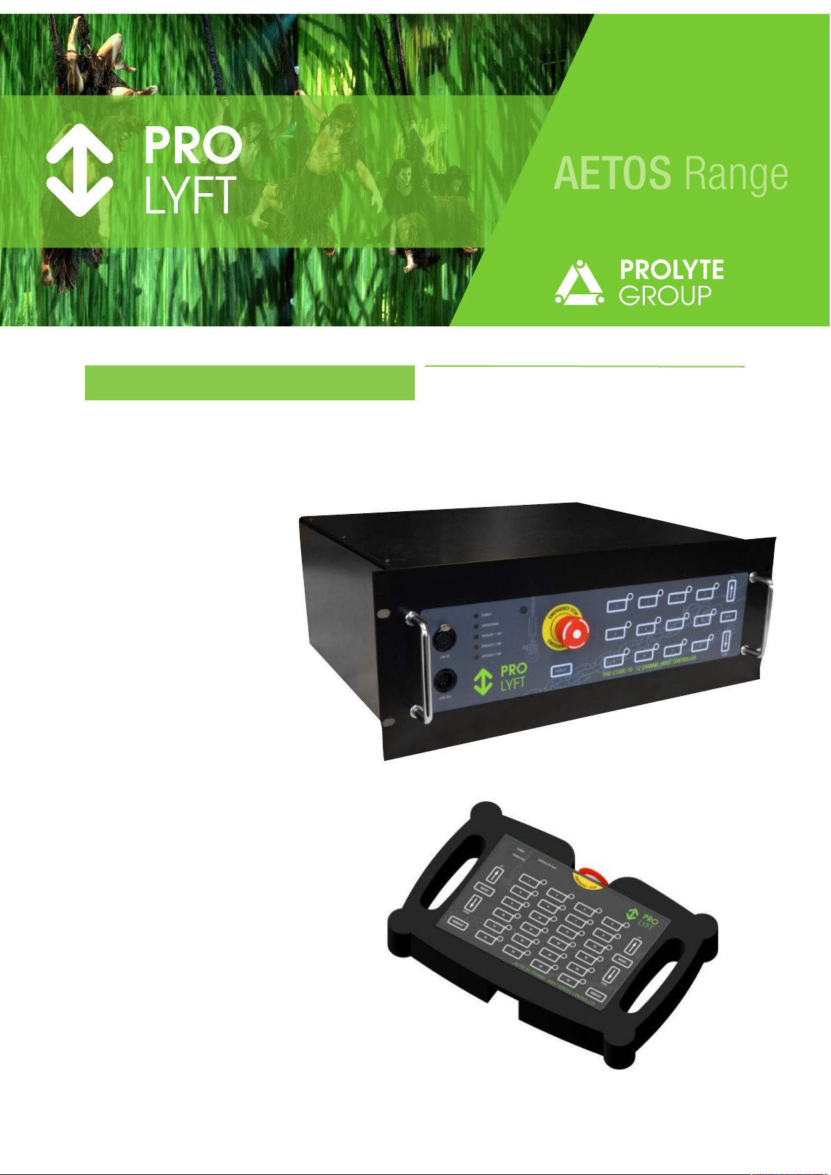
USER MANUAL AETOS HOIST CONTROLLERS
AETOS Hoist Controller Models:
3 phase 400 Volt:
PAE-C4DC-10
PAE-C8DC-10
PAE-C12DC-10
PAE-C4LV-10
PAE-C8LV-10
PAE-C12LV-10
3 phase 230 Volt:
PAE-C4DC-11
PAE-C8DC-11
PAE-C12DC-11
PAE-C4LV-11
PAE-C8LV-11
PAE-C12LV-11
Remote control:
PAE-C24R-10
Page 2

AETOS Range
CONGRATULATIONS
Congratulations with the purchase of your new PROLYFT AETOS hoist controller.
Content of the box or flight case
You have received the hoist controller in a box or a flight case. The following should be included:
•
The hoist controller.
•
Manual
Before you start using the hoist controller
Before starting to use the hoist controller take care of the following:
•
Check the carton box or the flight-case for any transport damage. Contact your supplier if there is any damage found.
•
Check the voltage settings of the hoist controller on the sticker on the back of the controller. All hoist controllers come
standard with a 400V/3ph/50Hz setting.
•
Take care of the proper safety features for lifting loads.
•
Enjoy using the hoist controller.
Lifting over people
The PROLYFT AETOS hoist controllers are designed for controlling either Direct Control or Low Voltage Control hoists (depending on
the type of controller) to lift loads in entertainment environments. In order to control hoists that are lifting or suspending loads above
people extra measures (not included in the functionality of the AETOS hoist controllers) must be taken in order to create the right
safety level.
These measures must be based on local regulations or on the outcome of a Risk Assessment.
!
page !2
Version 2018-02-02
Page 3

1. GENERAL INFORMATION 4
!"#$%&'()*+,)(-$(,$%#-.(-$)"/() 0)
1(2"'%$#+-/) 0)
3%#-$(-%-4(51(6%#,) 0)
2. INCORRECT OPERATION 4
3. ELECTRIC CONNECTIONS 4
7+8(,)#-6"$9) 0)
3%:#.".)6+8(,)4+-/".6$#+-)6(,);+#/$<) 0)
7+8(,)+"$6"$)$+)$;();+#/$ /) 0)
=#,#-2)+*)$;()+"$6"$)4+--(4$+,9) >)
?;()?@ABC)-($8+,D)4+--(4$#+-9) >)
=#,#-2)+*)$;()?@ABC)-($8+,D)4+--(4$+,9) >)
4. FRONT PANEL 6
5. REAR PANEL 6
6. FUNCTIONAL DESCRIPTION 7
7;%/()+,E(,)E($(4$#+-) F)
G#,4"#$)&,(%D(,/) F)
!('(4$#-2);+#/$/) F)
G'(%,#-2)$;()/('(4$#+-) F)
!$%,$#-2)%).+H(.(-$) F)
IA37)*"-4$#+-) F)
J+4D#-2)$;()*,+-$6%-(') F)
J#2;$)+"$6"$)+*)$;()JKLM/) F)
!$%$"/)+*)$;()JKLM/) F)
K.(,2(-4N)!$+6) F)
7. LINKING CONTROLLERS 8
8. REMOTE CONTROL 8
G+--(4$#-2)$;(),(.+$()4+-$,+') O)
P6(,%$#-2)*,+.)$;(),(.+$()4+-$,+') O)
JKL)#-E#4%$#+-)+-),(.+$()4+-$,+') O)
9. REPLACING AN OUTPUT / SWITCH MODULE 9
10. CHANGING FROM 400V to 208/230V 9
11. SPECIFICATIONS 9
12. DIMENSIONS 9
EC DECLARATION OF CONFORMITY 10
page !3
AETOS Range
Page 4

1. GENERAL INFORMATION
Attention: All users must read these operating
instructions carefully prior to the initial operation. These
instructions are intended to acquaint the user with the
hoist controller and enable him/her to use it to the full
extent of its intended capabilities.
The operating instructions contain important information
on how to handle the hoist controller in a safe, correct and
economic way. Acting in accordance with these
instructions helps to avoid dangers, reduce repair costs
and downtime and to increase the reliability and lifetime of
the hoist controller.
Anyone involved in doing any of the following work with
the hoist controller must read the operating instructions
and act accordingly:
• Operation, including preparation, trouble shooting and
cleaning
• Maintenance, inspection, repair
• Transport
Apart from the operating instructions and the accident
prevention act valid for the respective country and area
where the hoist controller is used, also the commonly
accepted regulations for safe and professional work must
be adhered to.
The user is responsible for the proper and professional
instruction of the operating personnel.
Suitable for entertainment use
The PROLYFT AETOS hoist controllers are specially
designed for use in the Entertainment industry. They must
only control electric chain hoists that are suitable for use
in the Entertainment industry.
Combining the hoist controller with different type of
electric chain hoists might lead to unwanted, unexpected
or dangerous situations.
The PROLYFT AETOS hoist controllers are not designed
to control hoists suspending or lifting loads above people.
Read the manual of the electric chain hoists before
starting to operate them with the hoist controller.
Regulations
The accident prevention act and/or safety regulations of
the respective country for using manual and electric chain
hoists must be strictly adhered:
• Europe:
• Machine Directive 2006/42/EG
• Safety of Machinery NEN 12100:2010
• Germany: BGV D6, BGV D8
Additional regulations are in effect for lifting or suspending
loads over people.
Germany: SQ P2
The Netherlands: NPR8020-10
United Kingdom: BS7950-1
Maintenance/Repair
In order to ensure correct operation, not only the
operating instructions, but also the conditions for
inspection and maintenance must be complied with. If
defects are found or abnormal noise is to be heard stop
using the hoist controller immediately.
Attention: Before starting to work on electrical
components the power-supply is to be cut off.
2. INCORRECT OPERATION
• Do not exceed the rated power capacity per controlled
channel.
• Do not lift stuck or jammed loads.
• Do not shortly and frequently actuate the up/down
switch.
• Do not control hoists if the movement of the load is not
visible from the operating position.
• Do not control hoists if you are skilled for lifting loads
• Do not use cables with damaged strain reliefs and/or
isolation.
• Do not use any input- or output cables that are not
suitable for the supplied voltage and / or current.
• Do not use the Thuja data connection (link in, link out)
with other network devices unless these devices are
specified to be suitable for use in the Thuja data
network.
• Do not connect the controller to a mains connection that
is not properly fused.
• Do not use the controller without proper grounding.
• Do not connect more then one hoist on a single
channel.
3. ELECTRIC CONNECTIONS
All electric connections must be used with respect for the
specified voltages and maximum power consumption.
Power input:
The power input connector is a 5pin CEEform connector
suitable for 3 phase 32Amp / 400Volt. 3 Phases, neutral
and ground.
Depending on the type of controller it can be plugged in to
either a 3 phase 400V or a 3 phase 230V mains
connections.
Make sure the mains connection is fused at maximum
32Amps per phase. It is advised to use circuit breakers
with a C or D characteristic.
Make sure the mains connection is properly grounded.
Improper grousing might lead to dangerous with the risk
of electric shock.
Maximum power consumption per hoist.
Each hoist channel is capable of switching an electric
chain hoist with maximum power consumption of 1,5kW.
Power output to the hoists
For each 4 hoist channels there is a Harting 16 output
connector.
Make sure the cables (and each individual wire of the
cable) connected to the output connector are suitable for
minimum 10Amps at 400V per wire.
To avoid voltage drops longer cables should have bigger
wire diameters.
page !4
AETOS Range
Page 5

Using local controllers (pickles) in combination with
Low Voltage controlled hoists.
The Low Voltage version of the Prolyft Aetos range of
controllers is NOT constantly powering the hoists. Power
is only switched to the hoists when the UP or DOWN
button is pressed.
This is done to avoid the use of local 1-way controllers
(the so called pickles) without an Emergency stop button.
Often these 1-way controllers are inserted in the control
line to create a local control at the hoist.
The use of any control system without an Emergency stop
function within reach of the operator is not allowed.
Wiring of the output connector:
Controllers for operating Direct Control hoists have the
following pin setting:
Pin 01: Hoist 1, L1
Pin 02: Hoist 1, L2
Pin 03: Hoist 1, L3
Pin 04: Hoist 1, Ground
Pin 05: Hoist 2, L1
Pin 06: Hoist 2, L2
Pin 07: Hoist 2, L3
Pin 08: Hoist 2, Ground
Pin 09: Hoist 3, L1
Pin 10: Hoist 3, L2
Pin 11: Hoist 3, L3
Pin 12: Hoist 3, Ground
Pin 13: Hoist 4, L1
Pin 14: Hoist 4, L2
Pin 15: Hoist 4, L3
Pin 16: Hoist 4, Ground
Controllers for operating Low Voltage Control hoists
have the following pin setting:
Pin 01: Power Hoist 1-4, L1
Pin 02: Power Hoist 1-4, L2
Pin 03: Power Hoist 1-4, L3
Pin 04: Power Hoist 1-4, Ground
Pin 05: Hoist 1, UP
Pin 06: Hoist 1, DOWN
Pin 07: Hoist 1, COMMON
Pin 08: Hoist 2, UP
Pin 09: Hoist 2, DOWN
Pin 10: Hoist 2, COMMON
Pin 11: Hoist 3, UP
Pin 12: Hoist 3, DOWN
Pin 13: Hoist 3, COMMON
Pin 14: Hoist 4, UP
Pin 15: Hoist 4, DOWN
Pin 16: Hoist 4, COMMON
The THUJA network connection:
The link-in and link-out connectors are THUJA data
network connectors, used to link controllers together or
connect them to remote control panels.
The THUJA network is based on a data-bus system
combining control data, power and emergency stop.
The THUJA network uses standard CAT5 cable in
combination with 7pin XLR connectors.
Wiring of the THUJA network connector:
The link-in or data-in connector is a Female connector.
The link-out or data-out is a Male connector.
Pin 1: Orange, 24V (link-in), nc (link-out)
Pin 2: White/Orange, Ground
Pin 3: Blue E-stop
Pin 4: Green RX2+ (link-in), TX1+ (link-out)
Pin 5: White/Green RX2- (link-in), TX1- (link-out)
Pin 6: Brown TX2+ (link-in), RX1+ (link-out)
Pin 7: White/Brown TX2- (link-in), RX1- (link-out)
Shield: White/Blue Ground
WARNI NG : wrong wiring of the THUJA network connector
might lead to defects.
WARNI NG : Since the ground of the network is connected
to the safety ground of the power supply a so called
“ground loop” can be created. Ground loops can affect the
data signal.
NEVER solve a ground loop problem by removing the
controller from the safety ground of the power supply.
page !5
AETOS Range
Page 6
4. FRONT PANEL
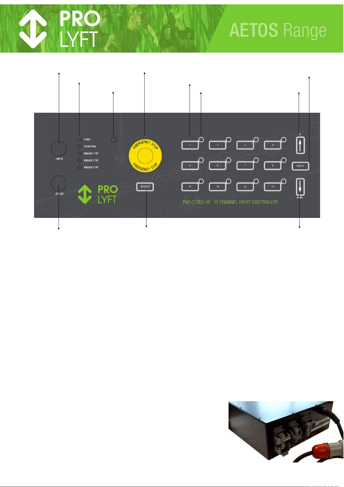
On the front panel you will find the following items:
LINK-IN CONNECTOR: THUJA network input connector
LINK-OUT CONNECTOR: THUJA network output connector
INDICATION LEDS: POWER
OPERATIONAL
BREAKER 1 TRIP
BREAKER 2 TRIP (8 and 12 channel only)
BREAKER 3 TRIP (12 channel only)
LIGHT SENSOR Sensor measuring the environment light, in order to adjust the light output of the LED's
EMERGENCY STOP Emergency Stop button
DESELECT SWITCH button to deselect all selected channels at once.
CHANNEL SELECTION individual hoist channel selection buttons
CHANNEL INDICATOR LED indicating the status of the channel
SELECT SWITCH button to press and hold in order to enable the select mode
UP SWITCH Starting button to move the selected hoist(s) in the UP direction
DOWN SWITCH Starting button to move the selected hoist(s) in the DOWN direction
5. REAR PANEL
On the rear panel you will find, from left to right:
OUTPUT CONNECTOR 1: Output connector for hoist 1 to 4
OUTPUT CONNECTOR 2: Output connector for hoist 5 to 8 (8 and 12 channel only)
OUTPUT CONNECTOR 1: Output connector for hoist 9 to 12 (12 channel only)
BREAKER 1 Circuit breaker for hoist 1 to 4
BREAKER 2 Circuit breaker for hoist 5 to 8 (8 and 12 channel only)
BREAKER 3 Circuit breaker for hoist 9 to 12 (12 channel only)
POWER CONNECTOR Mains power connector
NAME PLATE Sticker with serial number, voltage and CE mark !
page !6
AETOS Range
LINK-IN CONNECTOR
INDICATION LED’S
LIGHT SENSOR
EMERGENCY STOP BUTTON
HOIST CHANNEL SELECTION
CHANNEL INDICATOR
UP SWITCH
SELECT SWITCH
DOWN SWITCH
DESELECT SWITCH
LINK-OUT CONNECTOR
Page 7

6. FUNCTIONAL DESCRIPTION
Phase order detection
The controller detects automatically the order of the
incoming phases. Independent of the order of the
incoming phases the order of the phases on the output
are always clockwise for UP and anti-clockwise for
DOWN.
Circuit breakers
The circuit breakers on the rear panel are not to be used
as power switches. The status of the circuit breakers can
be read from the front panel LED indicators (see LED
indicators)
Each circuit breaker is connected to a 4-channel output/
switch module.
Selecting hoists
In order to select a hoist or a group of hoists press and
hold de SELECT button and press each HOIST
CHANNEL you want to add to the selection. Pressing the
HOIST CHANNEL for the second time will deselect the
hoist.
The LED next to each hoist channel button indicates the
selection of the hoist.
The selection can be done over all linked controllers.
Clearing the selection
Pressing the DESELECT button will deselect all selected
hoists.
Starting a movement
After creating a selection (or group) of hoists the group
can be moved up by pressing the UP button, or moved
down by moving the DOWN button.
If controllers are linked the UP and DOWN button on the
first controller will act like a MASTER UP or MASTER
DOWN.
BUMP function
When a group of hoists is selected, individual hoists out of
the group can be selected for adjustment (for example to
raise the middle hoist on a span lifted with 3 hoists).
Press and hold the HOIST CHANNEL button of the hoist
you want to adjust. The CHANNEL LED’s of the other
hoists out of the selection will switch off to indicate that
only the hoist from which the HOIST CHANNEL button is
pressed and hold is still active. Now, simultaneously,
press the UP or DOWN button to adjust the hoist. After
releasing the HOIST CHANNEL button to selection will
jump back in to the selected group.
The BUMP function does not work over linked controllers
in a Master/slave situation (will be changed in a future
software version)
If a remote control is used the BUMP function works on all
controllers connected to the remote.
Locking the frontpanel
The frontpanel can be locked by pressing and holding
both the SELECT and DESELECT button for 5 seconds.
Unlocking can be done in the same way.
Light output of the LED’s
The light output of the LED’s is automatically adjusted to
the ambient light by the LIGHT SENSOR.
Status of the LED’s
The LED INDICATORS on the front panel will show the
status of the controller:
POWER
Off: No power connected to the controller
On: Status OK. Power is connected to the
controller
BREAKER TRIP
Off: Status OK: All phases detected on output/
switch module. No errors.
On: No or missing phases detected on output/
switch module
Blink 1/5 Communication timeout detected by CPU
Blink 2/5 Communication timeout detected by
output/switch module (bit 14)
Blink 3/5 Communication CRC fault detected by
output/switch module (bit 15)
Blink 4/5 Estop validation fault
Blink 5/5 Estop equivalent fault
OPERATIONAL
On Status OK. E-stop OK,
(equivalent. output = 0x8000)
Blink 1/4 Estop fault
(equivalent. output = 0xC001)
Blink 2/4 Estop fault
(equivalent. output = 0xC002)
Blink 3/4 Estop fault
(equivalent. output = 0xC003)
Blink 4/4 Contact feedback wait on output/switch
module
Off Else
E-stop equivalent errors are caused by a delay in one of
the two E-stop circuits. Again pressing and after a few
second releasing the E-stop button is often solving the
problem.
Emergency Stop
The emergency stop (E-stop) button must be pressed in
any unwanted or unexpected situation. The E-stop affects
all linked controllers.
When the E-stop button is released the controller checks
all contactors for there expected status. If a contactor has
a different status then expected the E-stop circuit will
detect a fault and will not release the E-stop although the
button is back to its “safe” position. The operational LED
will blink accordingly.
page !7
AETOS Range
Page 8
7. LINKING CONTROLLERS
Controllers can be linked with a data link cable connected
from the link-out of controller 1 to the link-in of controller 2
etc. Maximum 10 controllers can be linked.
Controller 1 will act like a MASTER controller. The UP and
DOWN button on this controller will operate all selected
hoists on the linked controllers. Selecting and deselecting
must be done on every individual controller.
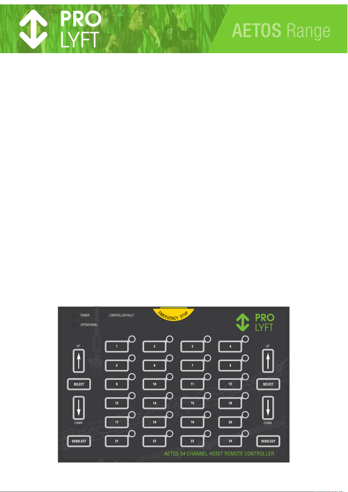
8. REMOTE CONTROL
Connecting the remote control
The remote control must be connected to the link-in
connector of the first controller. This controller will be
connected to the first channels on the remote control.
Any next controller linked to the first controller will be
connected to the next available channels on the remote.
Up to 24 channels.
Operating from the remote control
The remote control functions in exact the same way as
the frontpanels of the controllers.
The UP/DOWN/SELECT and DESELECT buttons on the
left and right side have exact the same functionality. It
makes it possible to make the remote left and right hand
operated.
When a remote is connected, the UP/DOWN buttons on
the controllers are disabled.
LED indication on remote control
Pressing any E-stop on a controller or a breaker trip on
one of the controllers will cause the LED’s of the affected
channels to blink.
!
page !8
AETOS Range
Page 9
9. REPLACING AN OUTPUT / SWITCH MODULE
Every controller is equipped with 1, 2 or 3 4-channel output
and switching modules. They can be either Low Voltage
Control or Direct Control modules.
Output/switch modules can be easily replaced for repair or
servicing. Turn off power before opening the controller.
When an output/switch module is replaced the new module
must be properly addressed with the dip-switches.
Addressing must be done before reconnecting the power
to the controller.
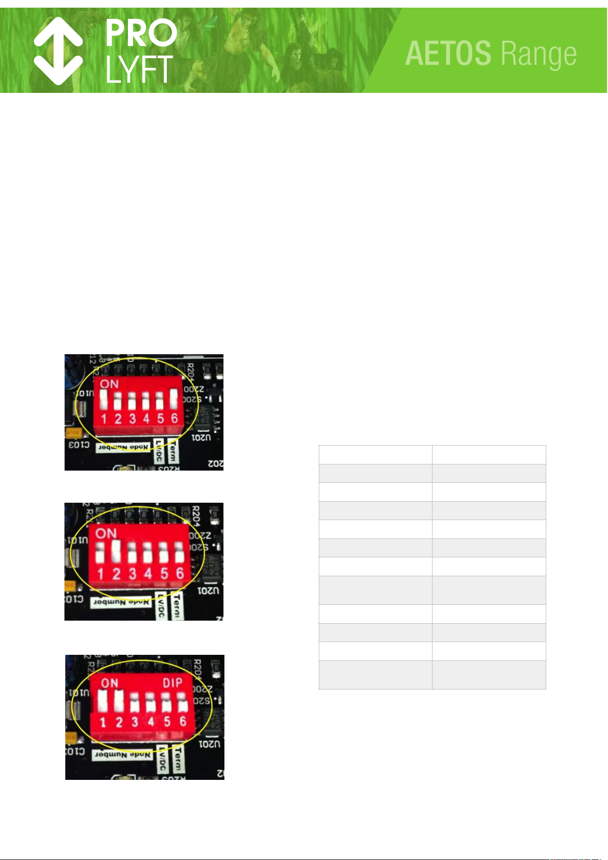
On each output / switch module there are 6 dip-switches.
-
Dip-switch 1 thru 4 represent the binary address setting of the
module.
-
Dip-switch 5 is to select DC or LV.
-
Dip-switch 6 is the terminator switch.
Setting the address dip-switches:
With the front panel of the controller towards you the output /
switch module on the right is no. 1, representing channel 1-4.
Module 1 (channel 1-4)
Module 2 (channel 5-8)
Module 3 (channel 9-12)
Setting the other dip-switches
Dip-switch no 5 is set to “off” for a DC module and set to “on”
for a LV module.
Dip-switch no 6 is only set to “on” on the module at the end of
the flat-cable. Normally this is the module on the right hand
side. On all other modules dip-switch 6 must be set to “off”.
Only 1 module can have dip-switch 6 set to “on”.
10. CHANGING FROM 400V to 208/230V
The Aetos controllers are standard configured for a 3phase
400V power supply. The controllers can be adapted to accept
a power supply in the range of 208/230V.
In order to this adaptation it is only required to re-connect the
internal 24V power supply (named as 250U1 in the electrical
drawing) from Neutral and L1 to L2 and L1.
The controllers are suitable for both 50 and 60Hz frequencies.
It is advised to mark the controller on the outside at the mains
connector or the serial number sticker to show the new voltage
setting.
WARNING: Hoist running on 3x 208V will use the double
amount of current compared to hoists running on 3x 400V.
11. SPECIFICATIONS
The Prolyft Aetos controllers have the following general
specifications:
12. DIMENSIONS
All units are 19-inch cabinets
Depth from front to back is 38,6cm.
Handgrips on the front need 3cm.
Connectors on the back need 5cm minimum.
Height for 4way unit is 3HE
Height for 8 and 12 way unit is 4HE.
page !9
AETOS Range
7+8(,)/"66'N)Q/$%-E%,ER
0SSTU)V)6;%/(U)>S)+,)WS@X
7+8(,)/"66'N)Q%Y(,)%E%6Z-2R
[SO5[VSTU)V)6;%/(U)>S)+,)WS@X
T+'$%2(),%-2(
\5])^S_
7+8(,)4+--(4$+,
V[C.6)GKK*+,.U)V6;\`\a`L
P6(,%Z+-)$(.6(,%$",(
\>)5)\VS)bG
!$+,%2()$(.6(,%$",(
][S)5)\WS)bG
J#-D)#-5+"$
?;"c%)-($8+,D)4+--(4Z+-
3%:)"-#$/)$+)&()'#-D(E)Q8#$;+"$)
%EE#Z+-%')/6'#d(,/R
W
J(-2$;)+*)'#-D)4%&'(
ee.$,)Q/#-2'()4%&'(R
3%:)6+8(,)6(,)4;%--('
^U>D=)Q0SSTR
P"$6"$)4+--(4$+,
@%,Z-2)^W6#-
G#,4"#$)&,(%D(,)Q6(,)0)4;%--('/R
^SC.6U)G]4;%,%4$(,#/Z4)
Page 10

EC DECLARATION OF CONFORMITY
!"#$%%&'($"%)#*!+,#-$%,!")'.#/!')%01)#2334562578##9:;;)"(!<#==#:>#
We,
Prolyte Sales BV,
Industriepark 9
9351 PA Leek
The Netherlands)
hereby declare, that the design, construction and commercialized execution of the below mentioned machine complies with the
essential health and safety requirements of the EC Machinery Directive. The validity of this declaration will cease in case of any
modification or supplement not being agreed with us previously.
Furthermore, validity of this declaration will cease in case that the machine will not be operated correctly and in accordance with
the operating instructions and/or not be inspected regularly.
Machine description: Electric chain hoist controllers
PAE-C4DC-10
PAE-C8DC-10
PAE-C12DC-10
PAE-C4LV-10
PAE-C8LV-10
PAE-C12LV-10
PAE-C4DC-11
PAE-C8DC-11
PAE-C12DC-11
PAE-C4LV-11
PAE-C8LV-11
PAE-C12LV-11
Remote control:
PAE-C24R-10
Serial number: Serial numbers for the individual units are recorded
Relevant EC directives: EC Machine directive 2006/42/EC
Directive for Electrical Equipment 2006/95/EC
Authorized representative for technical data: Prolyte Sales BV, Industriepark 9, 9351 PA Leek, The Netherlands
www. prolyte.com, www.prolyft.com
Date of signing: 01-07-2014
Signed by: Michiel van der Zijde
Product Manager Prolyft
page !10
AETOS Range
Page 11

page !11
Prolyft Service Points:
Look at “service.prolyft.com” for the
latest update
Argentina:
TSD Group
Fonrouge 756
Buenos Aires 1408
Australia:
Design Quintessence
Unit 72, Turner Street, Port Melbourne
63-85
Victoria 3207
Belarus:
BelCultProject Service
Kommunisticheskaya 10
Minsk 220029
China:
Trinity Technology
Xia Mao 1st21
Guang Zhou 51425
Colombia:
Audio Concept de Colombia
Auto Norte 122-61
Bogota 11001000
Croatia:
Perinic-Sistemi d.o.o.
Vrhovec 28
Zagreb 10000
Finland:
Electro Waves Oy
Pilspantilankuja 6
Espoo FIN-02240
France:
Axente
Le Parc De l’Evenement, All 1
Longjumeau F-91160
Greece:
Omikron Pro Lighting
Dervenion 31
Athens 14451
Honduras:
Communicaciones Mango
Col.minas de oro calle 625
Tegucigalpa 00001
Hungary:
D.P.Music Kft.
Ratz L. 72
Pest 1119
India:
Modern Stage Service
35, new municipal market lodging road
New Delhi 110003
Indonesia:
Prolyft - Rajawali
JI Mendawai I 52
DKI 12130
Italy:
AudioSales
Via Ugo Blanchi 23
Sorbolo 43058
Japan:
Prolyte Doughty Japan
Honcho 1-25-7
Kawaguchi 332-0012
Japan:
All Creation
Fukaebashi 3-15-17
Osaka 537-0001
Korea, South:
Tongsuh tech
#2001 bldg.B, Woolim Blue9 Biz. Center
240-21
Seoul 157-861
Latvia:
Pro 1
Melluzu str. 1
Riga LV 1067
Lebanon:
Litewaves S.a.r.l.
Lteif Street Haddad Building
Beirut 1234
Lithuania:
STS Stage Technical Services
Aukstaiciu g. 7
Vilnius LT-11341
Malaysia:
P.A.P.
The Highway Centre Lot 59-1 Jalan
51/205
Petaling Jaya 46050
Mexico:
Gonher Pro Audio
Norte 35 771
Mexico City 02300
Netherlands, The:
Prolyft
Industriepark 9, 5M
9351 PA Leek
Netherlands, The:
Relight Productions BV
Hoge Bergen 2
4704 RH Roosendaal
Netherlands, The:
Controllux
Tankval 5
Alphen aan den Rijn 2408 ZC
Netherlands, The:
Rolight
Josink Kolkweg 18
Enschede 7545 PR
New Zealand:
Metro Productions Ltd
Thorndon Quay 129-131
Wellington 6141
Norway:
MultiTechnic as
Fernanda Nissensgate 1
Oslo N-0401
Philippines:
Stage Riggers
Katarungan St, Plainview 515
Metro Manilla 1550
Poland:
Prolight Sp. z.o.o.
Ul. 3 Maja 183
Pruszkow 05-800
Portugal:
Stagecom
Rua Salgado Zenha, Lote 6
Lisabon 2685 332
Romania:
Arena Events
Bld Marasti 65-67
Bucharest 011465
Russia:
Modific
Luzhnetskaya naberezhnaya 2/4 bld. 16
Moscow 119270
Russia:
Stagepro
Moskovsky PR 22
St Petersburg 190013
Singapore:
Loud Technologies Asia
Serangoon North Ave 4 50
Singapore 06-21
South Africa:
DWR Distribution
Block C, Unit 1, Kimbult Industrial Park 9
Zeiss Road
Johannesburg 2040
Spain:
Fresnel SA
Potosi 40
Barcelona SP-08030
Sweden:
Bellalite Ljusdesign AB
Mörners väg 122
Kronoberg 35246
Taiwan:
Starship Engineering Co, Ltd
Sec 2, Wuchang St., Wanhua District,
124-2
Ta ip e i 1 08
Turkey:
Focus Reklam Ve Produksiyon
Cendere Yolu 27
Istanbul 34408
United Arab Emirates
Provision AVL
KML Bldg109 Al Meydan Road
Dubai 31366
United Kingdom:
Hawthorn Theatrical Ltd
Crown Business Park 1
Leicestershire LE 14 3NQ
Venezuela:
Audio Concept Venezuela C.A.
Calle Madrid Entre Calles Mucuchies y
Trinidad. Qta Montesorino
Caracas 1060
AETOS Range
 Loading...