

Prolon M2000 SERIES, PL-M2000-FLX, PL-M2000-BLR, PL-M2000-HPS, PL-M2000-HYD Quick Start Manuals
...Page 1

REV.2.0
PL-QCK-M2000-EN
www.proloncontrols.com | [email protected]
17 510 rue Charles, Suite 100, Mirabel, QC, J7J 1X9
QUICK START GUIDE
M2000 SERIES
Page 2

© Copyright 2018 Prolon. All rights reserved.
No part of this document may be photocopied or reproduced by any means, or translated to
another language without prior written consent of Prolon. All specications are nominal and
may change as design improvements are introduced. Prolon shall not be liable for damages
resulting from misapplication or misuse of its products. All trademarks are the property of their
respective owners.
Page 3

REV.2.0 / PL-QCK-M2000-EN 3
Table of Contents
Boiler Controller (PL-M2000-BLR) ................................................................................. 4
FlexIO Controller (PL-M2000-FLX) ................................................................................6
Heatpump Controller (PL-M2000-HP & PL-M2000-HPS) ...............................................8
Hydronic Controller (PL-M2000-HYD) ...................................................................... 10
Make Up Air Controller (PL-M2000-MUA) ............................................................... 12
Rooftop Controller (PL-M2000-RTU & PL-M2000-RTUS) .............................................. 14
Compliance............................................................................................................... 16
Technical Specications ....................................................................................... 16
Page 4
REV.2.0 / PL-QCK-M2000-EN4
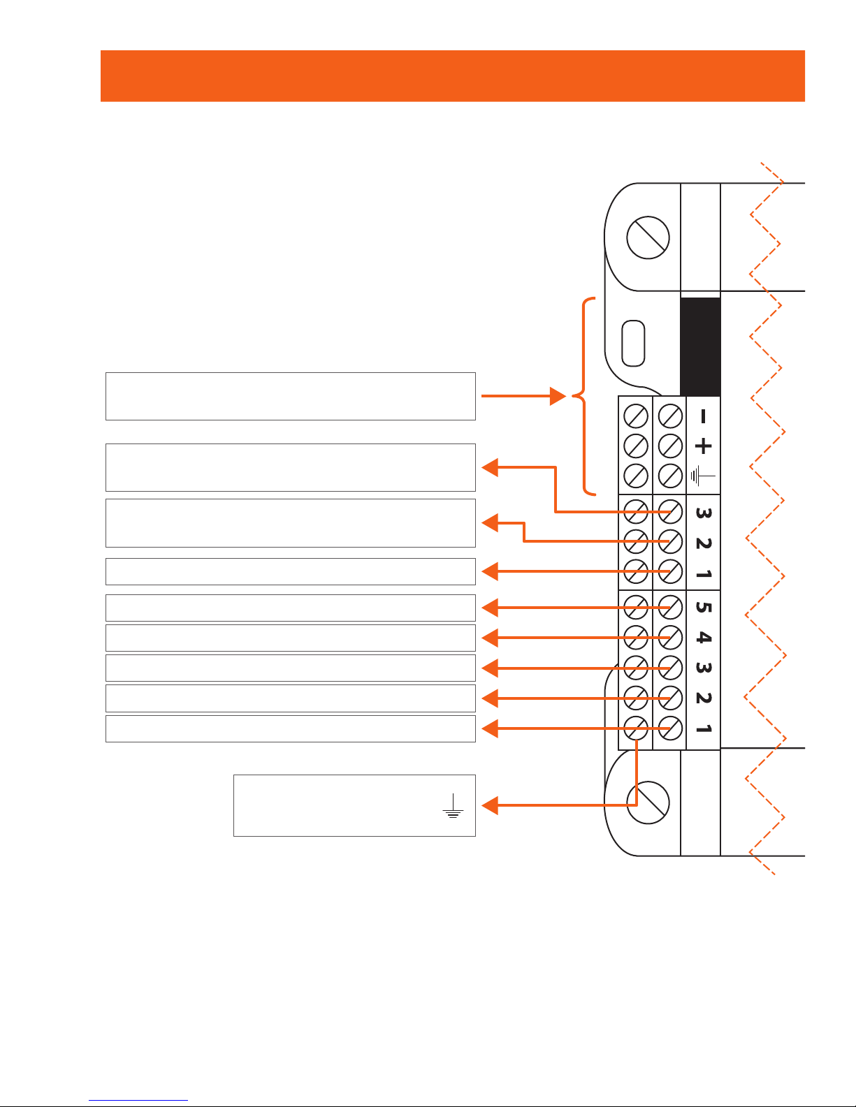
Boiler Controller (PL-M2000-BLR )
32-122 °F (0-50 °C) Non-condensing
INT Port: Incoming RS485 network
communication (Modbus)
AO 3 - Valve (0-10 / 2-10 / 0-5 VDC)
or backup modulating boiler
AO 2 - Modulating boiler
(0-10 / 2-10 / 0-5 VDC)
AO 1 - Pump 2 (ON/OFF) (0/10VDC)
DO 5 - Pump 1
DO 4 - Boiler stage 4
DO 3 - Boiler stage 3
DO 2 - Boiler stage 2
DO 1 - Boiler stage 1
Bottom row:
common for all outputs
Page 5
REV.2.0 / PL-QCK-M2000-EN 5
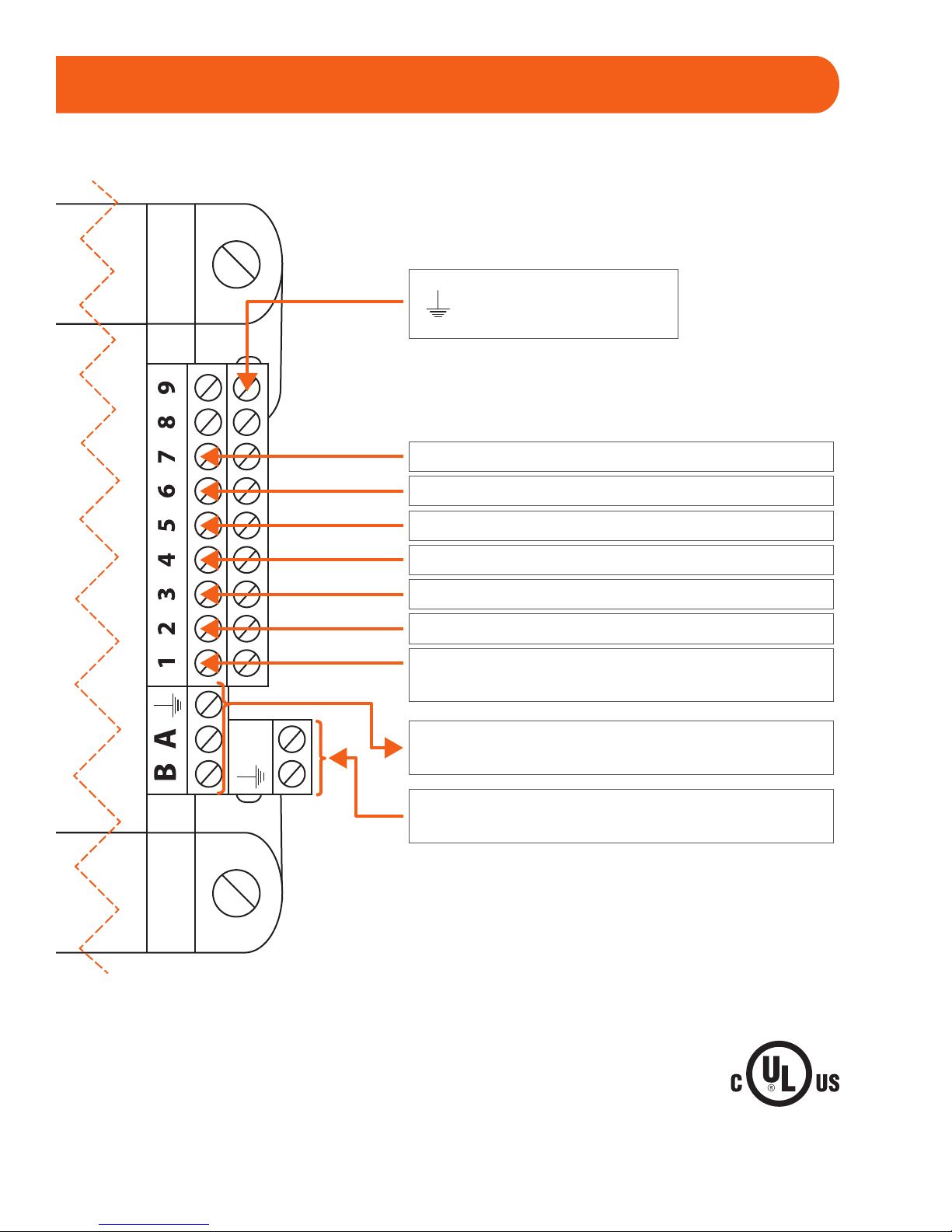
cULus Listed; UL 916 Energy Management Equipment, File E364757, Vol.1
24
VAC
NET Port: Incoming RS485 network
communication (modbus)
Controller’s power source
(24VAC - Class 2)
Bottom row:
common for all inputs
Proof of pump 2 (AO1) (dry contact)
Use max heat setpoint (dry contact)
Disable Boiler Call (dry contact)
Return water temp sensor (10K thermistor)
Proof of pump 1 (DO5) (dry contact)
Supply water temp sensor (10K thermistor)
Outside air temperature sensor
(10K thermistor)
Page 6
REV.2.0 / PL-QCK-M2000-EN6
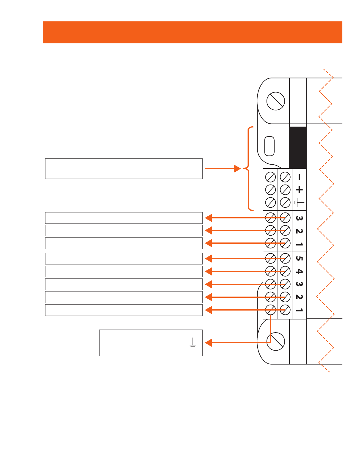
FlexIO Controller (PL-M2000-FLX)
32-122 °F (0-50 °C) Non-condensing
INT Port: RS485 network
communication (Modbus)
Analog output 1
Digital output 5
Digital output 4
Digital output 3
Digital output 2
Digital output 1
Bottom row:
common for all outputs
Analog output 2
Analog output 3
Page 7
REV.2.0 / PL-QCK-M2000-EN 7
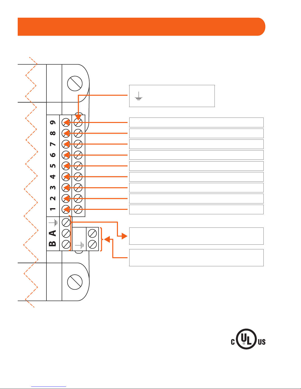
cULus Listed; UL 916 Energy Management Equipment, File E364757, Vol.1
24
VAC
NET Port: RS485 network
communication (Modbus)
Controller’s power source
(24VAC - Class 2)
Bottom row:
common for all inputs
Analog input 5
Analog input 6
Analog input 7
Analog input 8
Analog input 9
Analog input 3
Analog input 4
Analog input 2
Analog input 1
Page 8
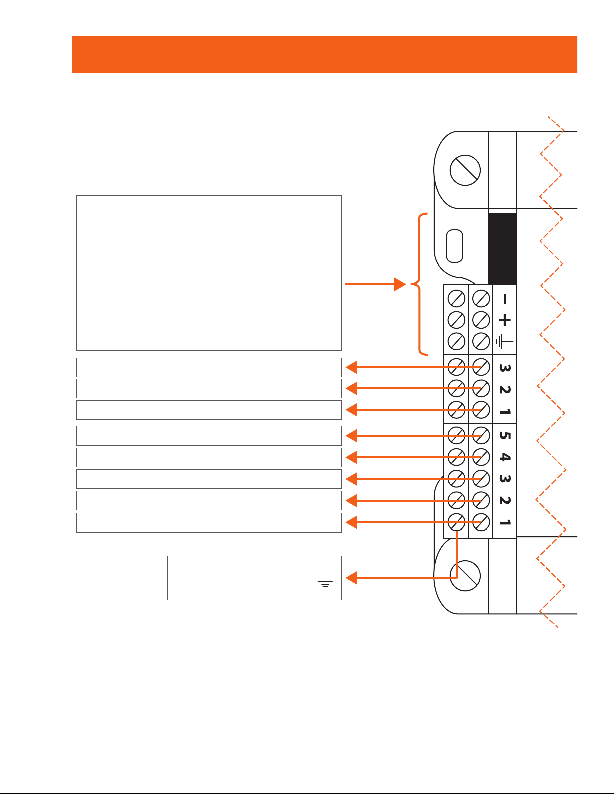
REV.2.0 / PL-QCK-M2000-EN8
Heatpump Controller (PL-M2000-HP & PL-M2000-HPS)
32-122 °F (0-50 °C) Non-condensing
Bottom row:
common for all outputs
AO3 - Bypass / VSD
AO2 - Economizer
AO1 - Preheating / Mod. Heat
DO5 - Aux Heat
DO4 - Rev Valve
DO3 - Compressor 2 (Y2)
DO2 - Compressor 1 (Y1)
DO1 - Fan (G)
HPS
INT Port: Prolon
digital temperature
sensor
- OR -
Incoming RS485
network
communication
(Modbus)
HP
Incoming
communication
from remote
computer
- OR -
Network Controller
(dual RJ45 and
terminal blocks)
Page 9
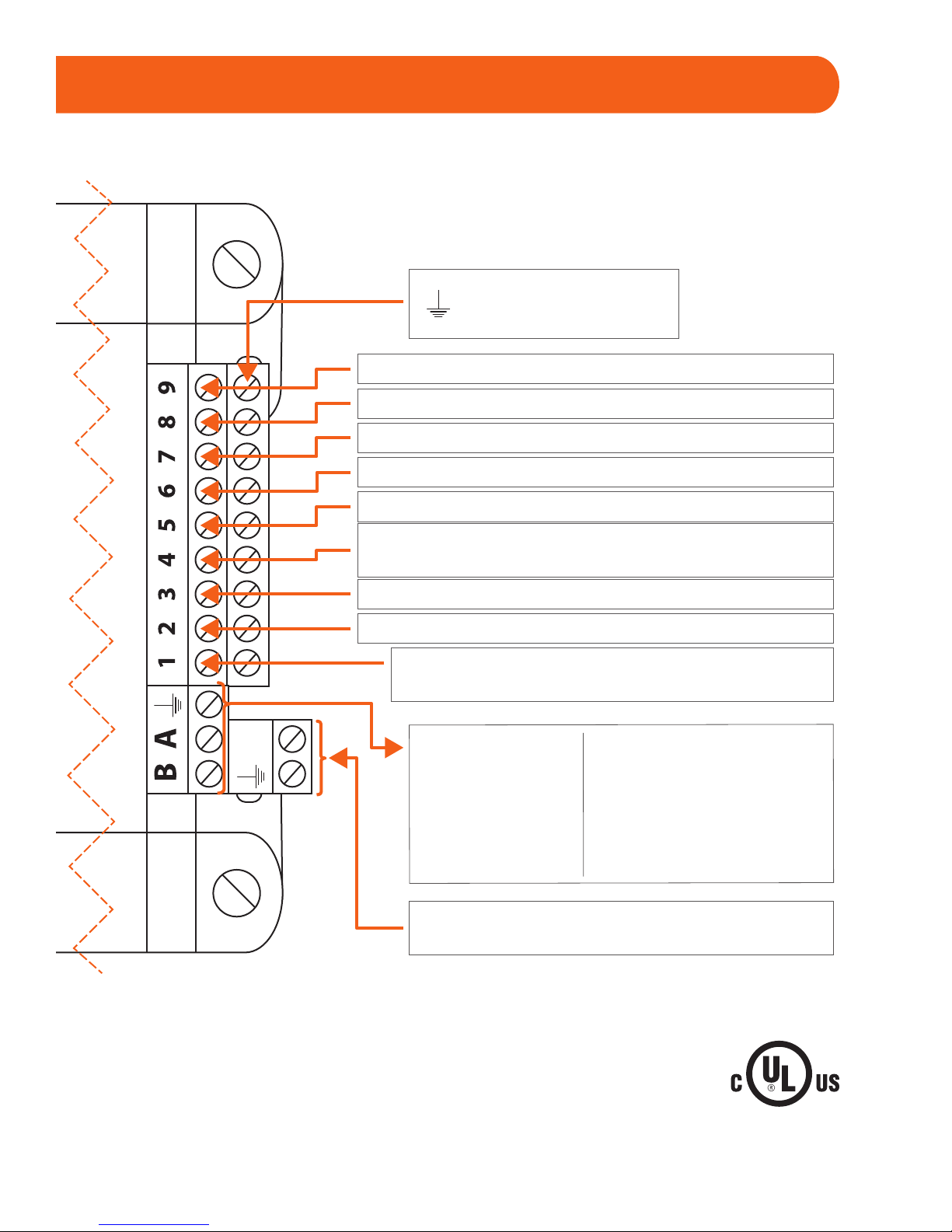
REV.2.0 / PL-QCK-M2000-EN 9
cULus Listed; UL 916 Energy Management Equipment, File E364757, Vol.1
24
VAC
Bottom Row:
common for all inputs
Static pressure (0-5 / 1-5V) (1 / 1.5 / 2 / 2.5 in)
Ext dry contact for alarm / CO2 sensor (4-20 mA)
External dry contact for proof of fan
Zone temperature setpoint (0-10K potentiometer)
Zone temperature sensor (10K thermistor)
Supply air temperature sensor (10K thermistor)
Return air temperature sensor (10K thermistor)
Outside air temperature sensor (10K thermistor)
Supply water temp sensor (10K thermistor)
Controller’s power source
Unit’s R&C terminals (24VAC)
Dry contact for clogged filter / Dry contact for
schedule override / Supply water temp (10k therm)
HPS
Net Port: Prolon digital
temperature sensor
- OR -
Incoming RS485 network
communication (Modbus)
HP
Outgoing network
communication
(to zones)
Page 10
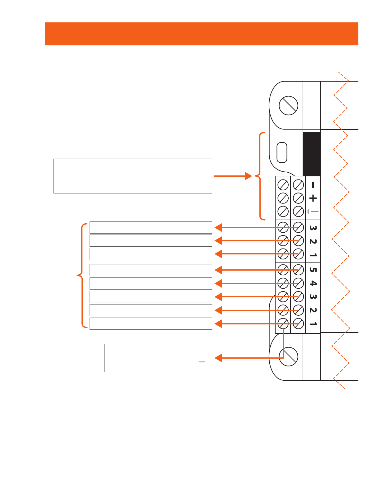
REV.2.0 / PL-QCK-M2000-EN10
Hydronic Controller (PL-M2000-HYD)
32-122 °F (0-50 °C) Non-condensing
Bottom row:
common for all outputs
Incoming communication from
remote computer -OR- Network Controller
(dual RJ45 and terminal Blocks)
Analog output 3 (0-10VDC)
Analog output 2 (0-10VDC)
Analog output 1 (0-10VDC)
Digital output 5 (24 VAC)
Output function varies
depending on chosen setup
Digital output 4 (24 VAC)
Digital output 3 (24 VAC)
Digital output 2 (24 VAC)
Digital output 1 (24 VAC)
Page 11
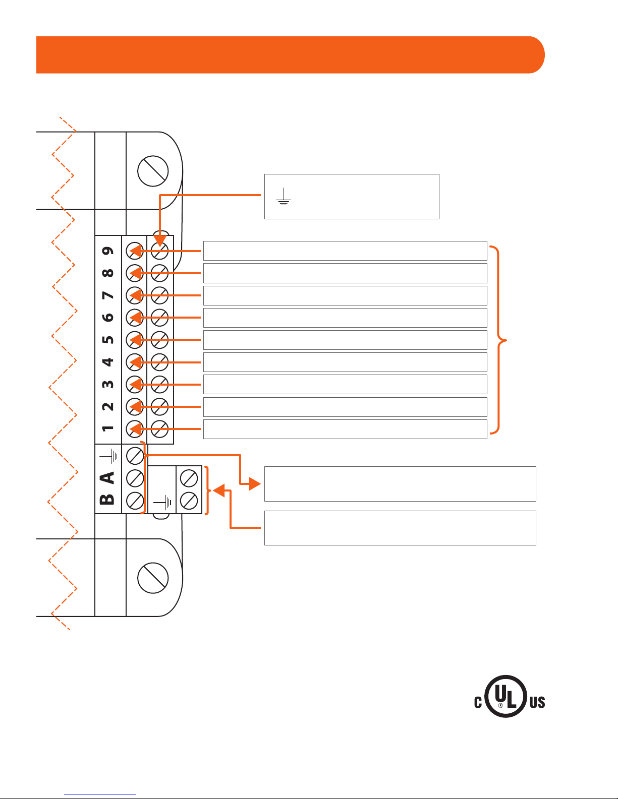
REV.2.0 / PL-QCK-M2000-EN 11
cULus Listed; UL 916 Energy Management Equipment, File E364757, Vol.1
24
VAC
Bottom row:
common for all inputs
Controller’s power source
Unit’s R&C terminals (24VAC)
Analog input 9 (thermistor / 4-20mA / 0-5VDC)
Analog input 8 (thermistor / 4-20mA / 0-5VDC)
Analog input 7 (thermistor / 4-20mA / 0-5VDC)
Analog input 6 (thermistor / 4-20mA / 0-5VDC)
Analog input 5 (thermistor / 4-20mA / 0-5VDC)
Analog input 4 (thermistor / 4-20mA / 0-5VDC)
Analog input 3 (thermistor / 4-20mA / 0-5VDC)
Outgoing network communication
(to zones)
Analog input 2 (thermistor / 4-20mA / 0-5VDC)
Analog input 1 (thermistor / 4-20mA / 0-5VDC)
Input function varies
dependint on chosen setup
Page 12
REV.2.0 / PL-QCK-M2000-EN12
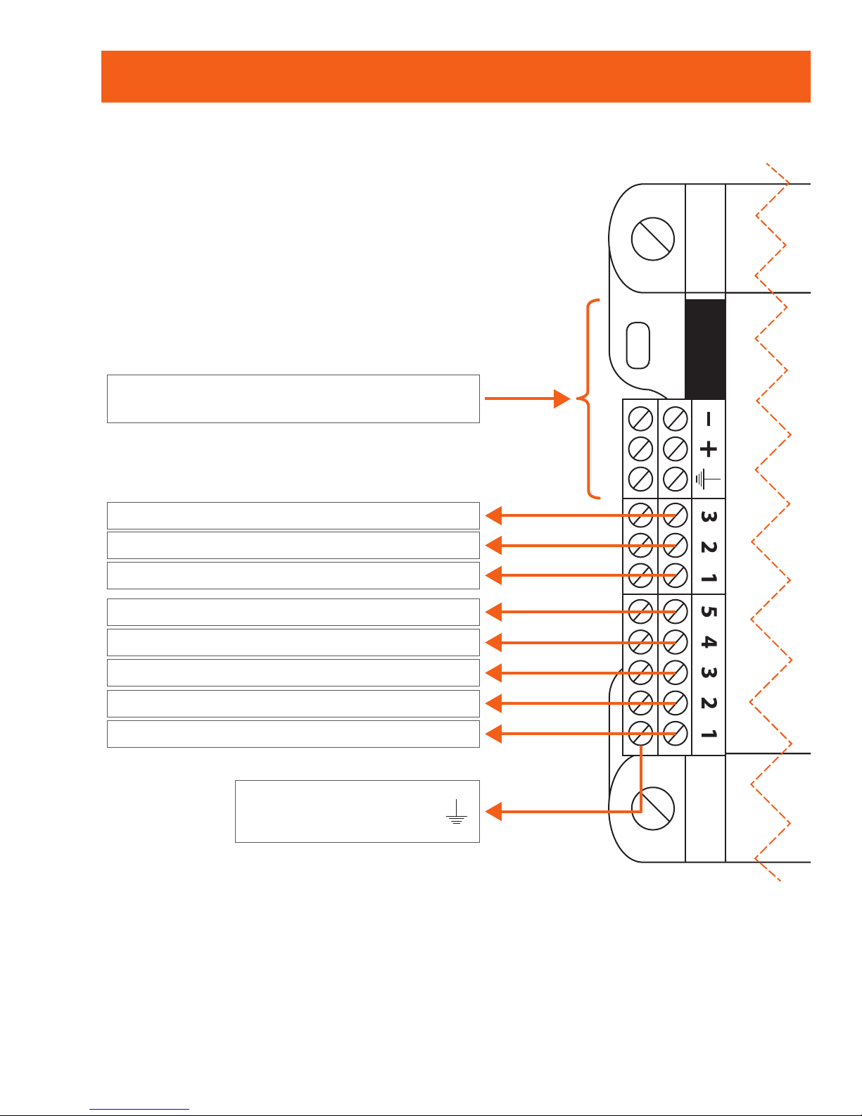
Make Up Air Controller (PL-M2000-MUA)
32-122 °F (0-50 °C) Non-condensing
Bottom row:
common for all outputs
INT Port: Incoming RS485 network
communication (Modbus)
AO3 - Variable frequency drive
AO2 - Cooling
AO1 - Modulating heat
DO5 - Alarm
DO4 - Preheat permission
DO3 - Fan
DO2 - Outside air damper
DO1 - Occupancy (exhaust)
Page 13
REV.2.0 / PL-QCK-M2000-EN 13
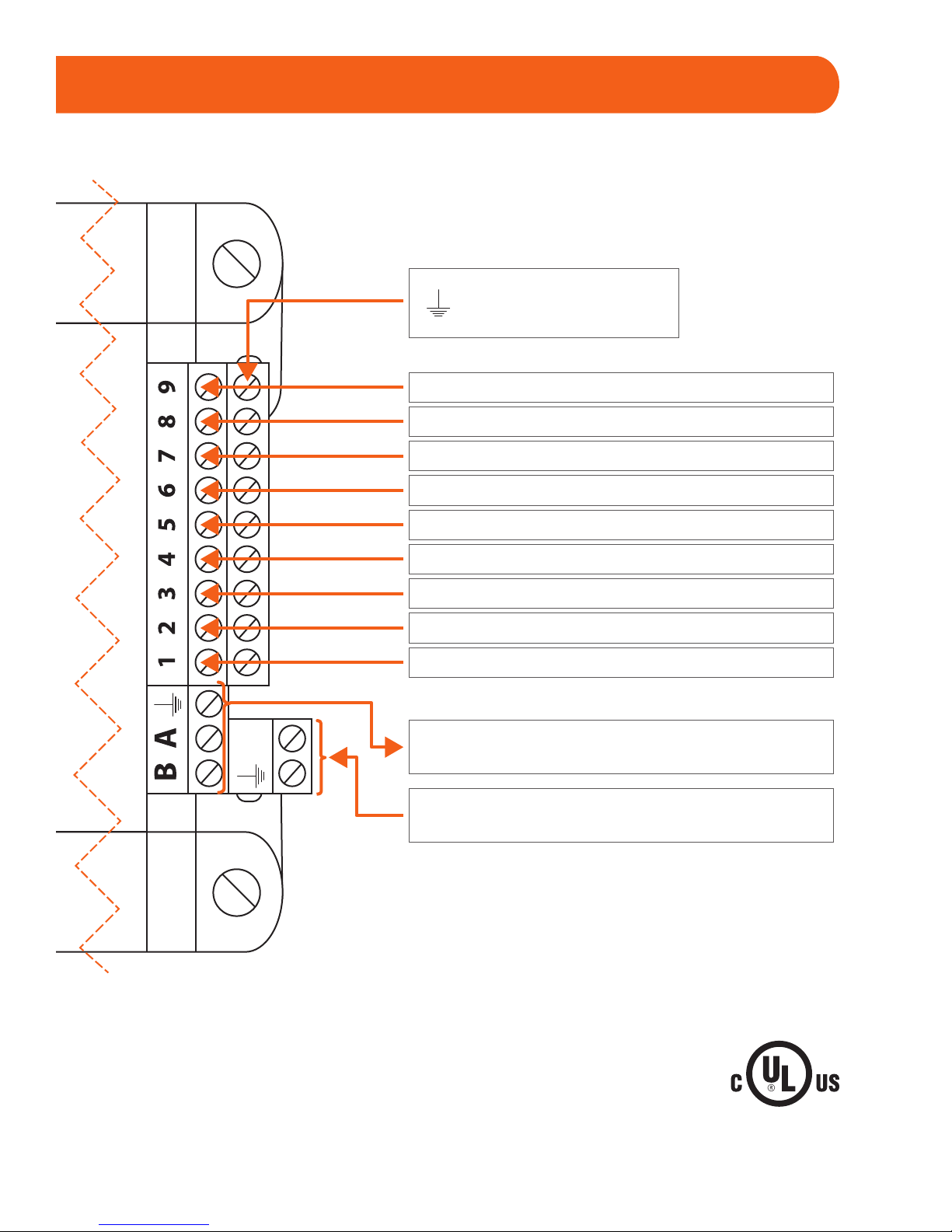
cULus Listed; UL 916 Energy Management Equipment, File E364757, Vol.1
24
VAC
Controller’s power source
(24VAC - Class 2)
Bottom row:
common for all inputs
NET Port: Incoming RS485 network
communication (Modbus)
CO2 (4-20mA) / Building pressure (0-5VDC)
Zone temperature (10K thermistor)
Outside temperature (10K thermistor)
Supply temperature (10K thermistor)
Manual reset
Proof of san
Proof outside air damper open
Proof exhaust 2 / Manual override
Proof exhaust 1
Page 14
REV.2.0 / PL-QCK-M2000-EN14
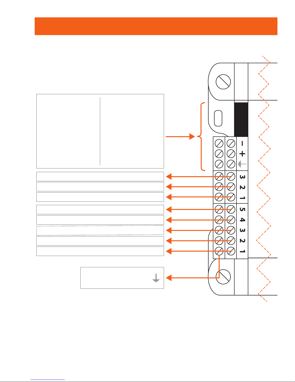
Rooftop Controller (PL-M2000-RTU & PL-M2000-RTUS)
32-122 °F (0-50 °C) Non-condensing
Bottom row:
common for all outputs
RTUS
INT Port: Prolon
digital temperature
sensor
- OR -
Incoming RS485
network
communication
(Modbus)
RTU
Incoming
communication
from remote
computer
- OR -
Network Controller
(dual RJ45 and
terminal blocks)
AO3 - Bypass / VSD
AO2 - Economizer
AO1 - Preheating / Mod. heat
DO5 - Heat (W2) / Exhaust fan / Baseboard
DO4 - Heat (W1) / Preheat perm.
DO3 - Cooling (Y2)
DO2 - Cooling (Y1)
DO1 - Fan (G)
Page 15
REV.2.0 / PL-QCK-M2000-EN 15
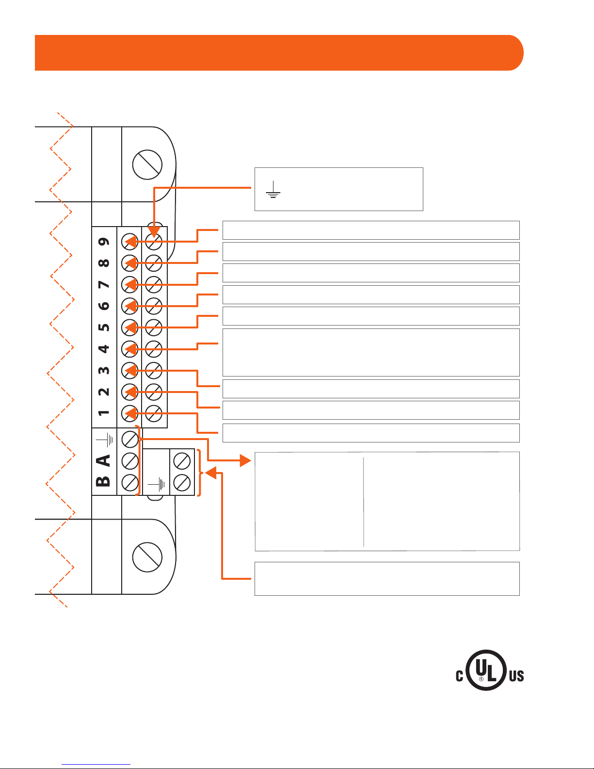
cULus Listed; UL 916 Energy Management Equipment, File E364757, Vol.1
24
VAC
Bottom row:
common for all inputs
Controller’s power source
unit’s R&C terminals (24VAC)
RTUS
Net Port: Prolon digital
temperature sensor
- OR -
Incoming RS485 network
communication (Modbus)
RTU
Outgoing network
communication
(to zones)
Static pressure (0-5 / 1-5V) (1 / 1.5 / 2 / 2.5 in)
CO2 sensor (4-20 mA)
External dry contact for proof of fan
Zone temperature setpoint (0-10K potentiometer)
Zone temperature sensor (10K thermistor)
Supply air temperature sensor (10K thermistor)
Return air temperature sensor (10K thermistor)
Outside air temperature sensor (10K thermistor)
Mixed air temp (10K therm) / Dry contact for
clogged filter / Dry contact for schedule override /
Auxiliary temp input (10K thermistor)
Page 16

REV.2.0 / PL-QCK-M2000-EN16
Compliance
Technical Specications
• cULus Listed; UL 916 Energy Management Equipment, File E364757, Vol.1
• CAN/CSA-C22.2 No. 2015-12, Signal Equipment
• FCC Compliant to CFR47, Part 15, Subpart B, Class B
• Industry Canada (IC) Compliant to ICES-003, Issue 5: CAN ICES-3 (B) / NMB-3(B)
• RoHS Directive (2002/95/EC)
FCC User Information
This device complies with Part 15 of the FCC Rules. Operation is subject to the
following two conditions: (1) this device may not cause harmful interference, and
(2) this device must accept any interference received, including interference that
may cause undesired operation.
Industry Canada
This Class (B) digital apparatus meets all the requirements of the Canadian
Interference-Causing Equipment regulations.
Cet appareil numérique de la Classe (B) respecte toutes les exigences du
Réglement sur le matériel brouilleur du Canada.
Supply: 24 VAC ±10%, 50/60 Hz, Class 2
Power: 5 VA (consumption), 40 VA (Input)
 Loading...