

-
Copyright © 1981, Pro-Log Corporation
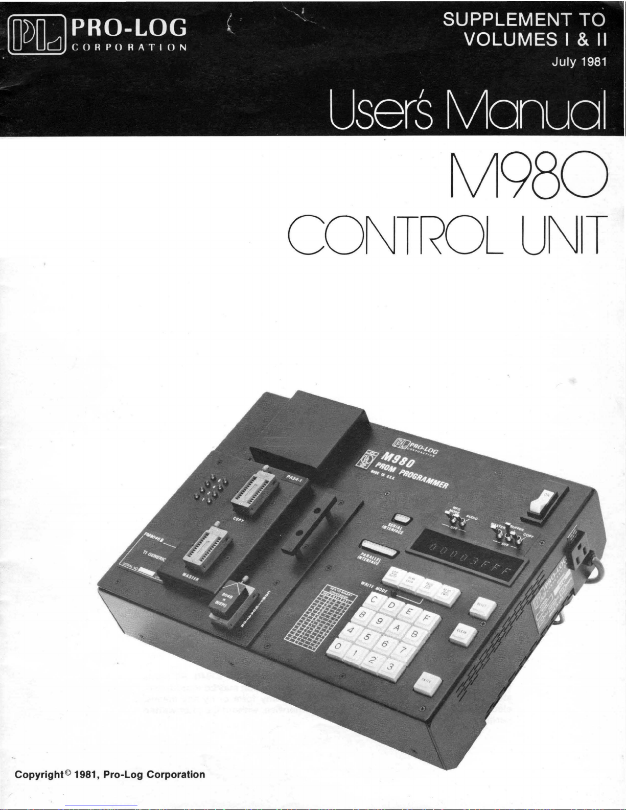
M980
CONTROL
UNT
The
information
be
entirely
reliable.
Furthermore,
equipment
or
others.
The
reserves
described
material
the
such
in
right
in
this
However,
information
any
this
manual
to
change
manual
license
is
specifications
has been
no
responsibility
does
under
the
subject
carefully
not
convey
patent
to
change,
without
reviewed
is
assumed
to
rightof
and
notice.
and
for
the
purchaser
Pro-Log
Pro-Log
is
believed
to
inaccuracies.
of
the
Corporation
Corporation
WARRANTY:
from
defects
published
years
expressed
quential
The
option,
been
repair
final
or
replaced,
warranty
the
repaired
for
expendable
respect
except
PRO-LOG
for
M980
or
damages
liability
any
defective
subject
or
installation
determination
period,
to
custom
as
specifically
Seller
in
material
warrants
Control
implied.
as a
of
Seller
hereunder
to
abuse, misuse,
are
as
the
warranty
or
for
or
r'eplaced
items
equipment
that
and
workmanship
specifications
Units).
In
result
no
This
event
of
any
shall be
units
not
to
the
ninety
part
such
stated
which
are
covered
existence
shall
continue
(90)
whichever
as
lamps
or
products
in
writing
the
articles
for
one
warranty
will
Seller
alleged
limited
returned.
accident,
by
warranty.
and
days
following
period
and
by
Seller
furnished
and
year
from
is
in
be
liable
breach
to
replacing
Equipment
alteration,
Seller
cause
of
in
effect
date
is
longer.
fuses.,
produced,
and
perform
date
lieu
of
for
of
this
neglect,
shall
defect.
for
the
of
shipment
No
No
warranty
to
Buyer's
contained
hereunder
to
applicable,
of
shipment
any
other
special
warranty
or
repairing,
or
parts
which
unauthorized
have
the
As
to
items
remainder
by
liability
is
is
specifications
in
the
are
free
(two
warranty
or
conse-
provision.
at
have
right
repaired
of
the
Seller
assumed
made
with
contract.
its
of
of
Copyright
reserved.
stored
electronic,
permission
({:)
1981
by
Printed
in
the
in a retrieval system,
mechanical,
of
the
publisher.
Pro-Log
U.S.A.
Corporation,
No
or
transmitted,
photocopying,
part
of
this
or
otherwise,
Monterey,
publication
in
any
form
without
CA
may
93940.
be
or
by
the
All
rights
reproduced,
any
means,
prior
written

M980
CONTROL
SUPPLEMENT
VOLUMES I AND
UNIT
USER'S
TO
II
MANUAL
Table
Miscellaneous
Miscellaneous
Addenda
Addenda
Replacement
of
Contents
to
Vol.
B u f
fer
Ed
fer
B u f
Application
Application
RS-Z3ZC
RS-Z3ZC
Error
Ed
to
Vol.
Indications
Corrections
Corrections
I
i t i t -
Format
16K
Pages
RAM S pI
RAM
II
Note
Note
Wraparound
for
it.
In
t e r I e a v e
A -
Tektronix
B -
AMC
Selection
Vol.
and
Operation
to
Vol. 1 ...................................
to
Vol.
. . . . . . . . . . . . . . . . . . . . . . . . . . . . . . . .
Systems
(with
Features
I
II
.............................
................................
8550 and M980/9818-14
8
and
Z9
Interface
Address
of
Codes
Offset)
M980
RAM
...................
..............
Buffer
Interface
with
..........
Pages
1
1 & Z
......
M980
7 -3 5
..
7 -
..
A-l
..
B-l
ZO-3A
ZO-3B
ZO-3C
ZO-3D
ZO-3E
38
{~~=~~~
ZO-ZOC
ZO-ZOD
13-1
& 13-Z
i
July
1981
PAGE
i
V
MISCELLANEOUS
VOLUME I OF
CORRECTIONS
Some
FROM
5-17
of
the
TO
5-21
referenced
5-2 5-3
5-6
5-5
5-8 5-9
5-11 5-13
5-13
Section
BUFFER
5-15
12
title
APPLICATIONS
Example 1
Example 2
Example 3
M980
should
CORRECTIONS
USER'S
pages
MANUAL
should
read:
TO
be
changed:
Page
Page
Page
12-1
12-2
12-3
5-23
6-15
7-21
9-1
Add
note
"NOTE:
If
an
gang
Add
module,
note
"NOTE:
an
attempt
gang
module,
following
Illegal
attempt
following
Illegal
is
Under number
"affected".
Under number
Add
to
first
"Some gang
individual
modules
operating
first
Bi t Check
is
made
an
'EO'
will
first
Bit
Check
made
an
6,
7,
'EO'
the
to
will
change
display
paragraph:
may
instructions."
paragraph:
to
perform
be
paragraph:
does
perform
be
vary
does
not
an
displayed."
not
an
displayed."
the
word
should
from
these
apply
Illegal
apply
illegal
read
to
gang
Bit
Check
to
gang
Bit
modules.
Check
"deleted"
"1000".
operations.
modules.
with
If
with
to
See
read
the
a
a
1
July
1981
PAGE
17-5
18-3
18-4
18-5
19-1
19-10
MISCELLANEOUS
TO
VOLUME
CORRECTIONS
Under
format
Under
delete
Under
delete
Under
delete
COMPARE
(01,
"TTY
"Asterisk(*),".
PROGRAM
the
word
TTY
ERRORS,
"address
transmission".
Photograph
use
the
9814
Figure
as
ACTIVE?,
AND
square
19-9
follows;
A.
KEY
4,
"Set
I I
OF
M980
operations,
03,
or
05)
if
OPERATING
SEQUENCES
OPERATING
"listed"
second
field
is
incorrect.
computer
interface.
"Initialization":
START,
Change
OBSERVE
Mode
SET
the
9814-00
Active."
CORRECTIONS
USER'S
MANUAL
#5
should
desired."
(DATA
SEQUENCE,
and
replace
line
defini
An
tion"
M304
#1:
from
Each
INTERLOCK
note
IN
AND
to
read;
DISPLAY,.
read:
ONLY)
with
the
bottom:
and
replace
adapter
flow
MODE
NOTE:
"Key
9812-02"
"programmed".
wi
th
is
not
needed
diagram
should
ACTIVE,
DEPRESS
Delete
in
new
#5.
"data
to
read
ADDRESS
RESET
entire
20-3
20-6
20-7
Under 9818-
last
Under
20-3".
data
Under
read
after
Under
sent
Under
data
character
9818-06
Under
character
9818-10,
"page
title:
9818-11
after
9818-11,
interface".
a CR,LF".
00
"Remotely:"
LOCALLY:
Locally:
the
first
20-7"
delete
"(4800
REMOTELY:
receiving
first
Under
Add
note
Add
the
M980
will
change
add
M980
note
responds
paragraph:
"or
via
baud
maximum)."
add
end-of-record."
paragraph:
Remotely:
after
add
title:
note:
respond
ref.
"page
"After
with a CR
change
remote
note:
after
"(4800
"After
20-7"
receiving
ref.
interface."
"No
delete
"NAK"
recei
with a CR
to
ving
and LF".
read
"page
the
last
and LF.
"page
'ACK'
"or
the
or
via
words
20-3"
Add
'NAK'
remote
note
"and
baud maximum)."
the
to
is
1
July
1981
20-7
20-9
20-11
20-12
20-14
20-15
Under
9818-12,
interface".
Under
9818-16,
interface".
Under
9818-18,
interface".
The
after
active
In
last
the
9818
the
Adapter.
al
ternately
adapter.
The
IC
number
the
"Baud
section
For
the
2732.
(09B),
The
and
Add
sentence
QXY
or
format.
sec
0 n d
"
Add
be
and
Rate"
of
the
MDS#235,
addresses
E8A3
first
note
first
first
on
QXN
par
a g
note
added
type
section
table
the
(OA3).
paragraph:
after
paragraph:
paragraph:
this
page
command
rap
h ,
to
figure
between
referenced
plus
are
for
IC
number
for
the
title:
returns
aft
e r
pins
the
the
is
MDS#235
delete
"(4800
delete
delete
should
the
"MD
S lOB"
20-3
4 and 5
in
the
addresses
MDS#230.
A82
are
read:"
M980
that
third
in
and
the
E89A
"or
baud
"or
"or
add
a
the
via
remote
maximum)."
via
via
Keying
to
the
" 0 r
remote
remote
ENTER
last
M3
jumper
of
the
M304
paragraph
"Location"
IC
type
(09A),
is
E89B
04
can
of
a
20-17
20-19
20-20
Under
"
...
Under
MOTOROLA
terminal.",
MOTOROLA
paragraph;
terminal
MOTOROLA
EXORcisor
female
a
Pro-Log
Under
read:
address
Under
replace
will
TEKTRONIX
"2.
field
DTE
"below"
EXORcisor
add:
EXORcisor
add
and
thi s note:
the
EXORcisor
II
is
a
connector
provide
S002A
Using
to
be
AND
DeE
with
"(See
M304
cable
II.
at
is
The
with
the
this
MDL,
the
instructions
uploaded
OPERATION,
"in
II,
fourth
diagram
II,
diagram
The
the
cable
original
cable
a
male
other
end.
connection."
UPLOAD
from
first
Figure
20-7".
paragraph,
below)".
shown
between
cable
between
connector
The RC-1S
TO
S002A: Change
on
page
the
M9S0
paragraph,
beneath
the
sent
the
M304
at
20-3,
RAM
Buffer."
following
the
keyboard
with
and
one
end
cable
select
last
fifth
the
the
and
from
#2
the
line:
to
2
Volume I
Sect
ion
July
1981
7
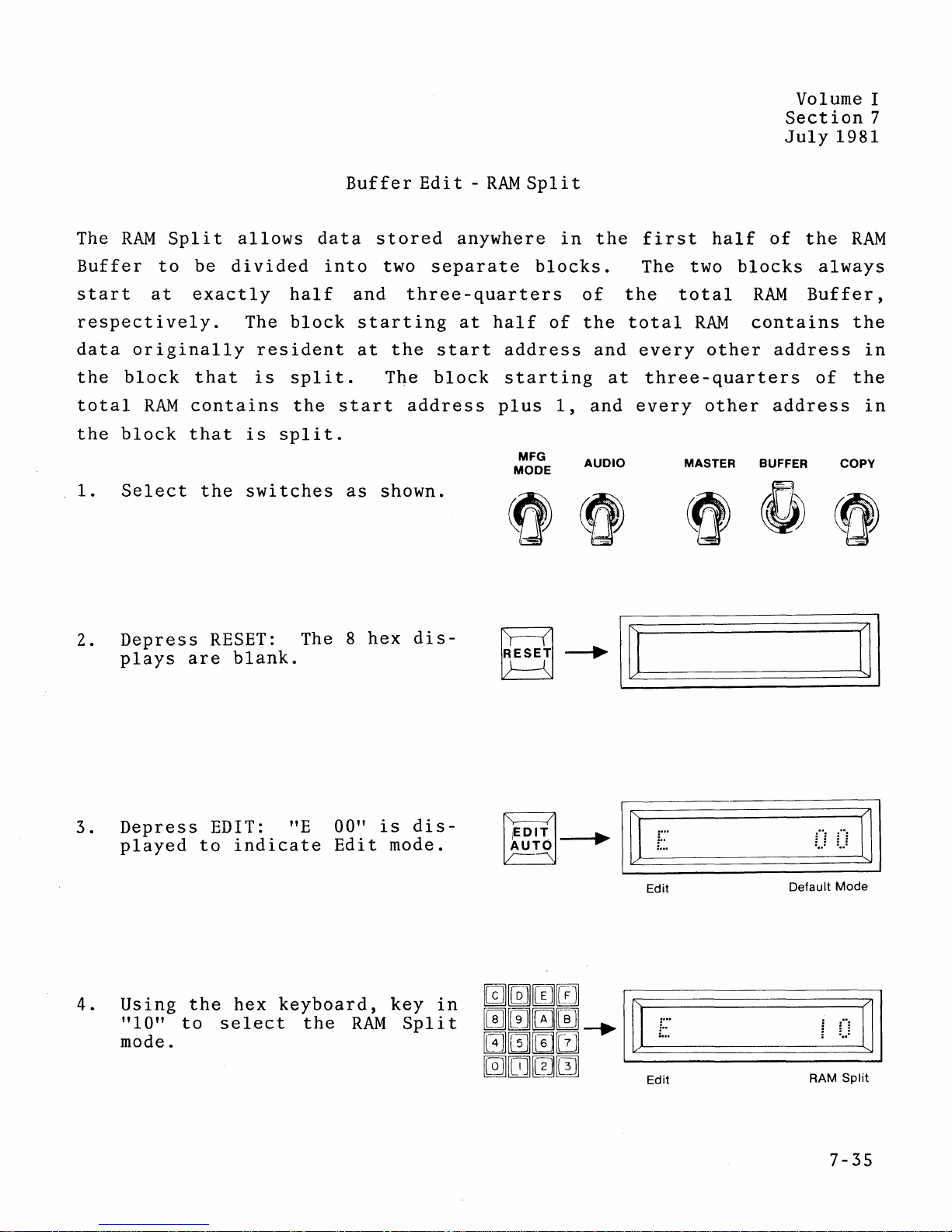
RAM
The
Buffer
start
respectively.
data
the
total
the
1.
Split
to
at
originally
block
RAM
block
Select
allows
be
di
vided
exactly
The
resident
that
contains
that
the
is
is
switches
data
half
block
spli
the
split.
Buffer
into
and
t.
start
as
Edi
stored
two
three-quarters
starting
at
the
The
address
shown.
t -
RAM
anywhere
separate
at
half
start
block
plus
Spl
i t
in
blocks.
of
address
starting
1,
MFG
MODE
the
of
the
and
at
and
AUDIO
first
The two
the
total
every
three-quarters
every
half
total
RAM
other
other
MASTER BUFFER
of
blocks
RAM
contains
address
address
the
RAM
always
Buffer,
the
of
the
COpy
in
in
2.
3.
4.
Depress
plays
Depress
played
Using
" 1
0"
to
mode.
RESET:
are
blank.
EDIT: "E 00"
to
indicate
the
hex
s e
Ie
The 8
keyboard,
c t
the
hex
is
Edit
RAM S pI
dis-
dis-
mode.
key
in
0000
i t
0.
GJ0
~~[]~
[9]00
m0
:
•
...
I~
Edit
00
Default
~I
Mode
I I
-.
nl
F !
.
~U
==
..
==..
====================~=--
~E-d-it------------RA-M-S-P-lit~
..
i
IJ
.
7-35
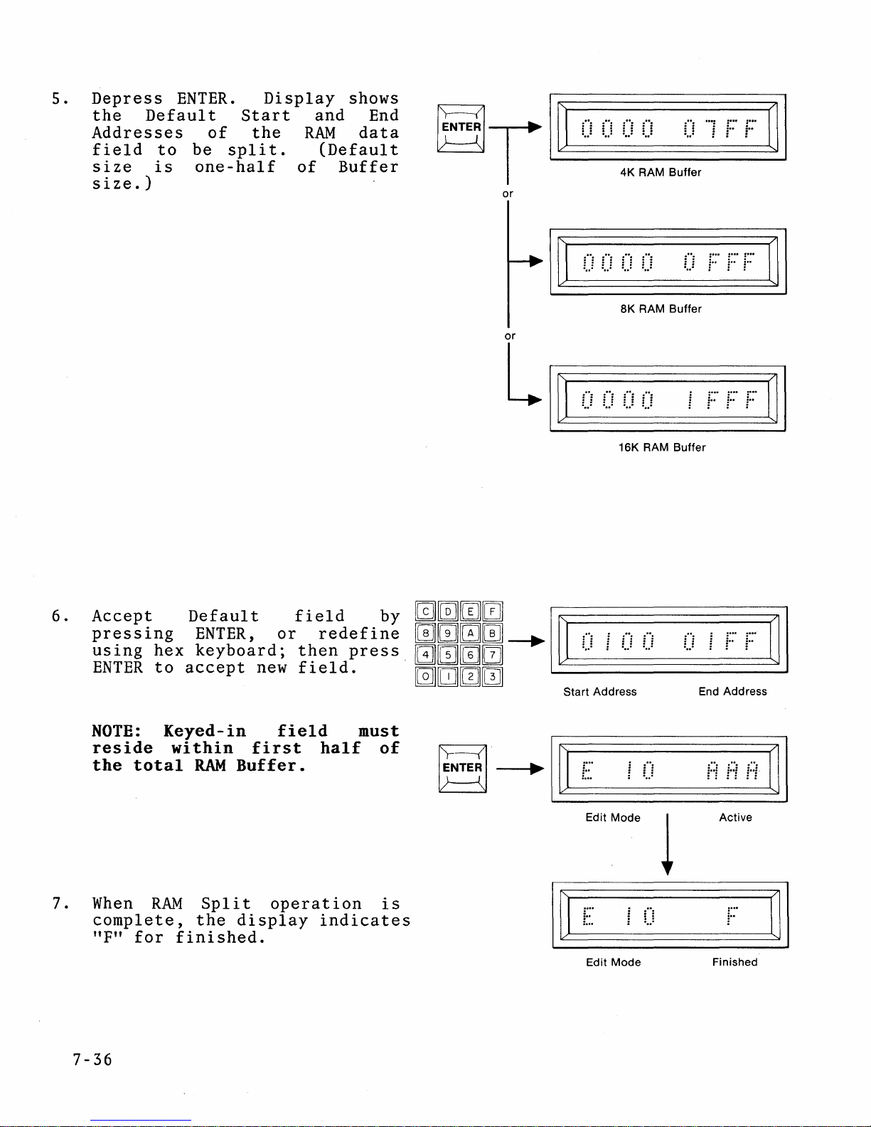
5.
Depress
the
Addresses
field
size
size.)
Default
to
is
ENTER.
of
be
spli
one-half
Display
Start
the
t.
and
RAM
(Defaul
of
shows
End
data
Buffer
t
~
T
or
or
L
0
I~
IC=::==
I~
IC=::==
0======0
0
4K
RAM
8K RAM Buffer
1)
0======0
0
16K RAM Buffer
=====u
Buffer
=====F
~F
:
... : ... : ...
U
in
i""
~F
F
i""
F
~
I
IJ
I
~
I
6.
7.
Accept
pressing
uSIng
ENTER
NOTE:
reside
the
When
complete,
"F"
hex
to
Keyed-in
total
RAM
for
Default
ENTER,
keyboard;
accept
within
RAM
Split
the
finished.
or
new
field
first
Buffer.
operation
display
field
redefine
then
field.
half
indicates
by
press.
must
of
is
mmmm
~~~~-+"~
I
0 i 0
1)
i··
""
i··
IJ
I
[@][I][0][1]
Start Address
rTE~
~I~
t:.
Edit
Mode
""
End Address
HHH
~I
Active
1
Mode
0
~I
Finished
:
...
I~
Edit
7-36
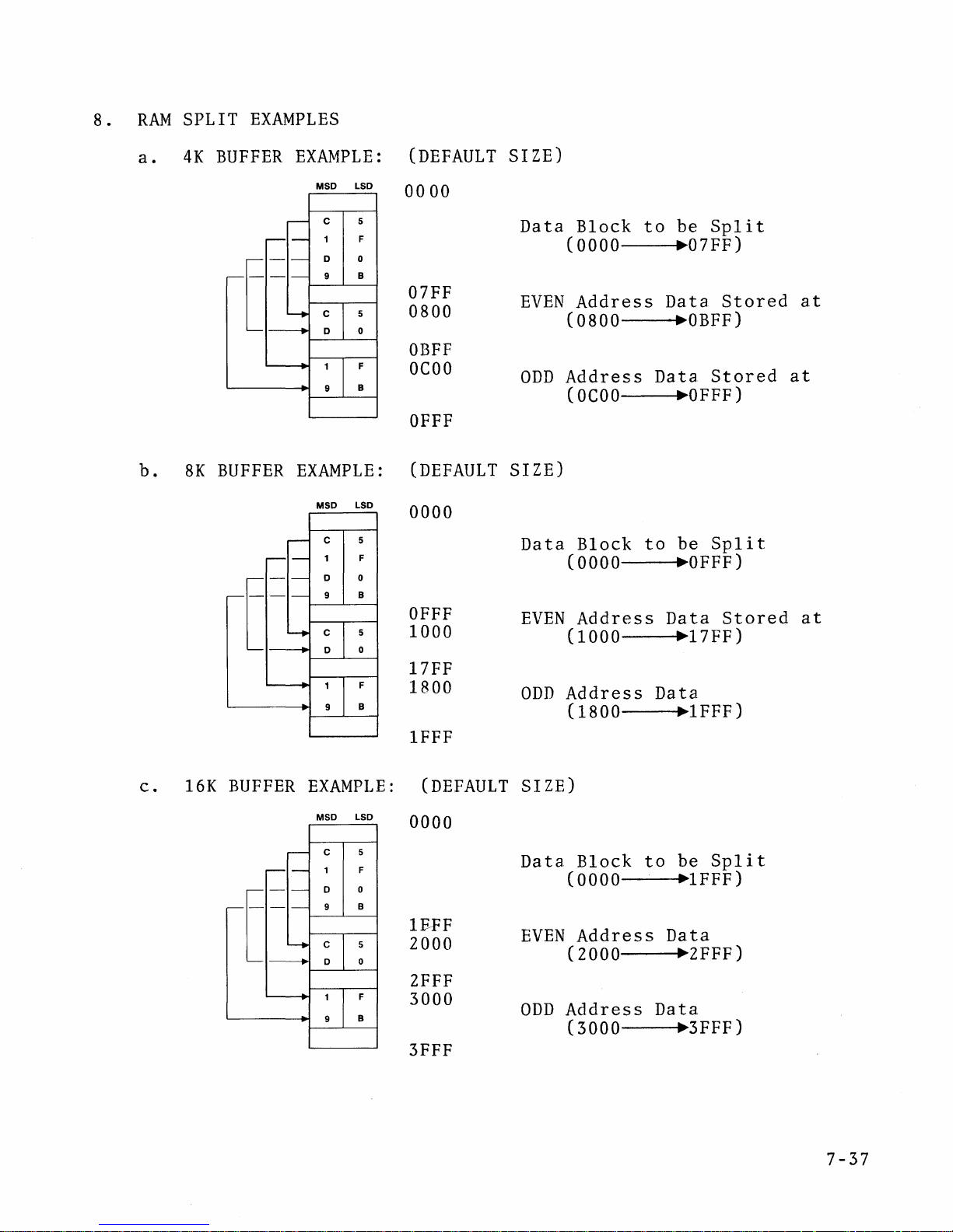
8 .
RAM
SPLIT
EXAMPLES
a.
b.
4K
8K
BUFFER
-
[
BUFFER
EXAMPLE:
LSD
MSD
5
C
F
D 0
B
9
5
0
F
B
EXAMPLE:
LSD
MSD
c
F
0
B
5
0
F
B
(DEFAULT
00
00
07FF
0800
OBFF
OCOO
OFFF
(DEFAULT
0000
OFFF
1000
17FF
1800
1FFF
SIZE)
Data
EVEN
ODD
SIZE)
Data
EVEN
ODD
Block
(0000
Address
(0800
Address
(OCOO
Block
(0000
Address
(1000
Address
(1800
to
be
.07FF)
Data
.OBFF)
Data
~OFFF)
be
to
.OFFF)
Data
~17FF)
Data
.1FFF)
Split
Stored
Stored
Split
Stored
at
at
at
c.
16K
BUFFER
EXAMPLE:
MSD LSD
-
[
(DEFAULT
SIZE)
0000
c
F
D
B
1FFF
ZOOO
Data
EVEN
Block
(0000
Address
(ZOOO
to
Data
be
Split
.1FFF)
.ZFFF)
ZFFF
F
B
3000
ODD
Address
(3000
Data
.3FFF)
3FFF
7-37
Volume I
Section
July
1981
7
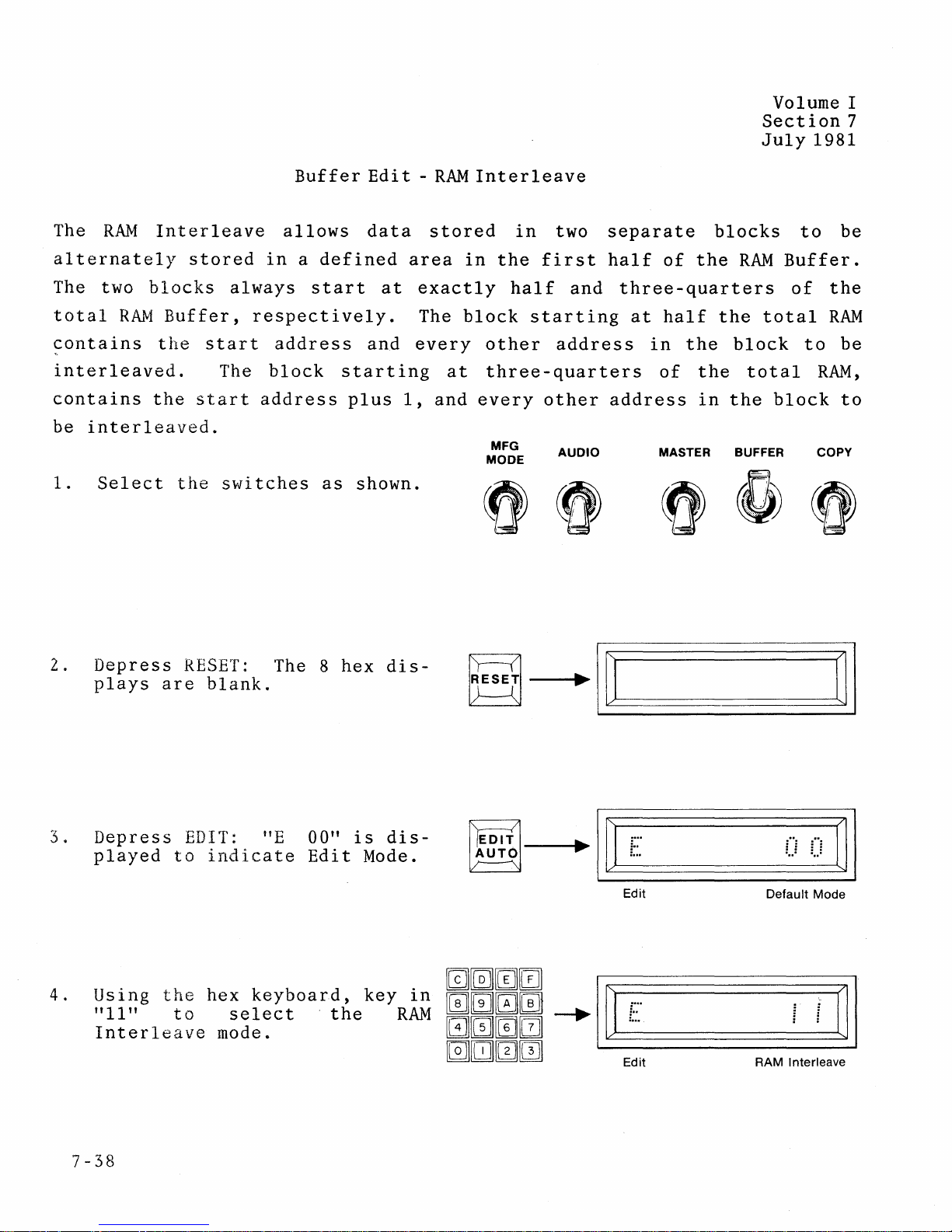
The
RAM
alternately
The two
total
blocks
RAM
contains
interleaved.
contains
be
interleaved.
1.
Select
the
Interleave
stored
always
Buffer,
the
start
The
start
the
switches
Buffer
allows
in a defined
start
respectively.
address
block
address
start
as
plus
shown.
Edi t -
data
area
at
and
ing
1,
RAM
stored
in
exactly
The
block
every
a t
and
Interleave
in
two
the
first
half
and
starting
other
address
three -quarters
every
MFG
MODE
other
AUDIO
separate
half
of
blocks
the
three-quarters
at
half
in
the
of
the
address
in
MASTER BUFFER
RAM
the
block
total
the
Buffer.
of
total
block
to
to
RAM,
COpy
be
the
RAM
be
to
2.
3.
4 .
Depress
plays
are
Depress
played
Using
"
11
to
the
" t 0 s e
Interleave
RESET:
blank.
EDIT:
indicate
hex
mode.
The 8
HE
00"
Edit
keyboard,
Ie
ct·
t
hex
is
Mode.
key
he
dis-
dis-
in
RAM
Edit
Edit
..
u
Default Mode
Interleave
RAM
~I
7-38

s.
Depress
the
addresses
where
(Default
Buffer
Default
the
size.)
ENTER.
of
data
size
Display
start
the
will
is
and
RAM
be
one
shows
end
Buffer
stored.
half
~TI~~
or
or
....
C_Of)
4K RAM
8K
RAM
16K RAM Buffer
_u
Buffer
..
Buffer
----"FF~I
F F F
~I
6.
7.
Accept
pressing
uSIng
ENTER
NOTE:
reside
of
When
operation
display
finished.
hex
to
the
Default
ENTER,
keyboard;
accept
Keyed-in
within
total
the
RAM
RAM
is
indicates
field
or
then
new
field.
field
the
first'
Buffer.
Interleave
complete,
"F"
by
redefine
press
must
half
the
for
mmm~
[§][IJ]m[mJ
aNTE~
~
I
~~
1_.·)
j_.
Start Address
~
....
I~
Edit
Mode
I
~
....
Edit
Mode
0_0
_U
End Address
_----"~
............
j
..
j
j··i
i··i
I
~I
Acti,ve
Finished
7-39

8.
RAM
INTERLEAVE
a.
4K
BUFFER
EXAMPLES:
EXAMPLE:
MSD
LSD
(DEFAULT
0000
SIZE)
b.
8K
BUFFER
C 5
F
D 0
9 B
5
c
D
0
F
9
B
EXAMPLE:
MSD
LSD
F
B
07FF
0800
OBFF
OCOO
OFFF
(DEFAULT
0000
OFFF
1000
Data
EVEN
ODD
SIZE)
Data
EVEN
Block
(0000
Address
(0800
Address
(OCOO
Block
(0000
Address
(1000
to
Store
..
07FF)
Data
..
OBFF)
Data
~OFFF)
to
Store
.OFFF)
Data
~17FF)
Interleave
Interleave
Data
Data
7-40
c.
16K
BUFFER
F
B
EXAMPLE:
MSD
LSD
5
F
0
B
5
0
F
B
17FF
1800
IFFF
(DEFAULT
0000
IFFF
2000
2FFF
3000
3FFF
ODD
SIZE)
Data
EVEN
ODD
Address
(1800
Block
(0000
Address
(2000
Address
(3000
Data
~lFFF
to
Store
~lFFF)
Data
~2FFF)
Data
~
3FFF)
)
Interleave
Data

Volume
July
1981
II
There
8550.
pin
METHOD
8
are
One
to
1 (No
Operating
NOTE:
1.
Do
Install
Connect
via
2.
Switch
3.
Select
of
the
two
requires
pin
20
Modifications)
Sequence
not
M304
the
an
RC-18
power
9818-14
M980
methods
on
the
install
adapter
terminal
cable
on,
via
User's
for
interfacing
no
modifications.
M304
M304
adapter.
adapter
in
the
connector
or
equivalent.
and
turn
the
hex
Manual
TEKTRONIX
the
with
parallel
to
on
the
on-line
keyboard,
(Vol.
II).
APPLICATION
8550 and M980/9818-14
M980/9818-14
The
other
M980
power
interface
JI0l
of
the
modem
using
the
requires
with
ON.
connector.
Tektronix
switch.
procedure
the
a
jumper
8550
on
NOTE
A
INTERFACE
Tektronix
from
DOS/SO
page
20-3
To
Download
The
8550
to
the
M980
The 8550
formats.
a.
b.
c.
to
the
executes
RAM
Buffer.
is
capable
To
dump
TEK
HEX
format,
WHEX:
INTEL
format,
WHEX:
MOTOROLA
WHEX:
M980
the
WHEX
of
in:
REMO
enter
I
REMO
format,
M
REMO
from
the
Tektronix
command,
downloading
enter
(Start
enter
to
to
(Start
(Start
the
Address)(End
the
Address)(End
to
Address)(End
to
data
8550:
8550:
the
dump
to
8550:
8550
the
file
the
M980
Address)
Address)
Address)
to
JI0l
RAM
00
00
00
and
Buffer
thereby
in
three
A-I

July
1981
Data
in
inclusive,
line
at
checksum
be
reset
8550
To
prints
Upload
Execution
initiates
1.
The 8550
three
a.
b.
the
transfers
a
time
error
and
to
of
the
formats.
TEK
INTEL
program
(see
occurs,
the
the
DOS/SO
the
Tektronix
the
RHEX
upload
is
capab
HEX
format,
RHEX:
format,
RHEX:
memory
in
"Address
an
operation
Prompt
command
operation.
Ie
To
upload
enter
REM1
enter
I
REM1
the
"E6"
of
from
selected
is
rerun.
(
8550
by
rece
in:
to
to
the
the
format
Offset"
displayed.
When
).
from
the
i v
ing
the
the
8550,
8550:
8550:
Start
description,
the
M980.
before
da
ta
Address
to
the
The
M980
operation
a
from
the
to
M980
p.
and
local
M980
the
End
RAM
20-3A).
8550
is
completed,
list
RAM
Address,
Buffer,
must
operation,
Buffer
one
If
then
the
a
in
c.
MOTOROLA
2.
Key
3.
Depress
The
M980
Addresses
format
(see
completed,
RHEX:
in
Start
ENTER.
outputs
to
the
format,
M
and
the
the,
8550' s system
"Address
8550
REM1
End
RAM
Offset"
prints
enter
to
Address,
Buffer
description,
the
DOS/50
8550:
the
using
data
the
located
memory, 1
Prompt
hex
ine
p.
(
keyboard
between
by 1 ine
20-3A).
).
on
the
in
When
the
M980.
Start
the
selected
uploading
and
End
is
A-
2

July
1981
--;;~3;;1
J101 I
RS-232
I
I
I
I
I
•
•
•
•
2
3
4
5
6
•
I
I
I
I
~~_-1
•
•
•
7
8
20
DB25S
DATA
DATA
CTS
FROM 8002A
FROM
RTS
HELD
CONTROLLED
DSR
HELD
DCD
HELD
DTR
TO
PROGRAMMER
HIGH
SIGNAL
HELD
HIGH
HIGH
BY
BY
BY
GROUND
BY
HIGH
PROGRAMMER
TO
8002A
PROGRAMMER
PROGRAMMER
PROGRAMMER
PROGRAMMER
BY 8002A
•
~
•
~
•
•
•
•
DB25P
2
3
4
5
6
7
8
20
r,;;--
Adapter
I
I
~
I
•
I
•
I
•
I
•
I
•
I
•
I
•
I
L~~5S_
Figure
A-I
M980/8550
Interconnect
A-3

July
1981
METHOD
Operating
NOTE:
1.
2 -
Do
Install
the
via
2.
Switch
3.
Select
of
the
To
Download
The 8550
to
the
M980
(Modifications)
Sequence
not
install
M304
modem
an
connector
RC-18
power
cable
on,
9818-14
M980
to
User's
the
executes
RAM
Buffer.
M304
adapter
and
via
the
Manual
M980
the
WHEX
adapter
in
to
J103
or
equivalent.
turn
hex
from
command,
the
parallel
(paper
on
the
keyboard,
(Vol.
the
Tektronix
with
on-line
II).
to
M980
tape
using
dump
power
interface
port)
modem
the
8550
the
file
on.
connector.
of
the
switch.
procedure
to
J103
Connect
Tektronix
on
page
and
thereby
8550
20-3
Enter
Data
to
in
inclusive,
at
a
time.
and
8550
is
completed,
the
the
transfers
If
must
8550:
program
a checksum
then
the
be
8550
WHEX
PPTP
memory from
in
TEK-HEX
error
reset
and
prints:
(Start
the
format
occurs,
the
*WHEX*
Address)(End
Start
to
the
an
Address
"E6"
operation
EOJ.
Address)
M980
is
rerun.
to
the
RAM
Buffer,
displayed.
When
the
End
operation
Address,
one
line
The
M9S0
A-4

To
Upload
to
the
Tektronix
8550 from
the
M980
Execution
initiates
1.
Enter
2.
After
and
3.
Depress
The
M980
Addresses
When
uploading
of
the
to
selecting
key
in
ENTER
outputs
to
the
upload
the
the
the
is
RHEX
command by
operation.
8550:
RHEX
the
Start
on
the
the
RAM
8550's
completed,
PPTR.
9818-14
and
End
M980.
Buffer
system
the
the
8550,
active
Addresses,
data
located
memory,
8550
prints:
before
state
line
on
using
between
by
*RHEX*
a
the
the
line
local
M980,
hex
the
in
EOJ.
list
operation,
depress
keyboard.
Start
TEK-HEX
ENTER
and
End
format.
A-5

A-6

Volume
July
1981
II
When
1.
Use
2.
Make
port
3.
Connect
via
4.
Plug
S.
Turn
adapter
6.
Place
To
Download
interfacing
the
M304
sure
for
4800
the
the
RS-232C
the
M304
power on
while
the
to
the
adapter
that
assigned
M304
the
M980
the
AMC
baud
cable.
adapter
the
M980
the
M980
switches
M980
AMC
with
and
AMC
an
system
RC-18
has
maximum, and
AMC
RAM
into
and
power
in
Buffer
RS-232C
the
the
AMC
is
the
SYSTEMS
systems:
or
equivalent
an
RS-232C
even
parity.
port
parallel
system.
on.
ON-LINE
from
AMC
8 &
to
the
I/O
connector
Note:
and
MODEM
Systems
29
port
M304
APPLICATION
INTERFACE
cable.
available.
modem
on
Do
not
install
ON
positions.
8
or
29
NOTE
WITH
M980
Set
connector,
the
M980.
M304
B
the
1.
Determine
Example: UPI:
2.
On
the
The
M980
3.
Type on
The
the
the
"18
data
MaS
transfer
stored
TECH
AAA".
the
M980,
display
the
format.
is
assigned
depress
AMC
in
the
taking
RESET,
shows
console:
file
The
left-most
place.
RS-232C
key
"18
AAA".
STAT
PIP
named
When
port
8,
key
PUN:
PUN:
is
downloaded
display
completed,
name on
1,
key
= UPI:
=
(file
on
the
name
to
the
8,
the
M980
the
AMC
and
to
M980
M980
system.
ENTER.
be
downloaded)
RAM
flashes
di
splay
Buffer
"1"
while
shows
in
B-1

To
Upload
1.
Determine
Example: URI:
to
AMC
System 8 or
the
assigned
9 from
RS-232C
the
port
M980
RAM
name on
Buffer
the
AMC
system.
July
1981
2.
Type on
3.
On
The M980
Buffer.
Buffer
Addresses
ENTER.
The
of
data
the
format.
the
AMC
M980
M980
flashes
display
the
stored
M980
(This
system
the
M980,
display
Depress
or,
of
RAM
format
"0"
will
AMC
console:
depress
using
the
between
Buffer
to
terminate
while
show
shows
ENTER
the
data
is
sends
the
"12
STAT
PIP
RESET,
the
to
M980
you
wish
the
previously
transferred
a
"Control
a
transfer.)
transfer
MA".
RDR:
(file
key
8,
Start
upload
keyboard,
to
is
= URI:
name) =
key
and
upload
to
End
the
selected
the
Z"
character,
taking
1,
addresses
entire
key
to
AMC
The
place.
RDR:
key
2,
contents
in
the
the
AMC
Start
system
which
left-most
When
ENTER,
of
the
Start
system.
and
End
in
the
is
display
completed,
and
ENTER.
M980
of
the
and
Depress
addresses
INTEL
required
on
RAM
RAM
End
HEX
by
the
the
B-2

Volume I I
Section
July
1981
20
RS-Z3ZC
This
Address
determined
in
the
Address
Operation
1.
FORMAT
sequence
Receive
is
Install
the
M980
using
Connect
terminal
whichever
the
M304
modem
the
switches
SELECTION
allows
received
by
the
selected.
the
(power
RC-18
to
or
is
on-line
on
if
the
or
listed.
M980
and
List
M304
must
cable
system
modem
appropriate.
attached.
as
or
switch
shown.
(With
substitution
and
is
modes
adapter
be
off),
equivalent.
via
connector,
on
Select
Address
The
subtracted
until
on
M304
Turn
and
the
Offset)
of a Default
Address
from,
M980
MFG
MODE
Offset
or
is
AUDIO
Address
added
reset
is
to,
and
MASTER
for
the
First
automatically
all
addresses
a new
BUFFER
Default
COPY
2.
Turn
RESET.
blank.
3.
Depress
9818 RS-232C
shows
format.
4.
Select
key
is
shown.
displayed,
and/or
active
M980
"9818
pad.
power
The 8
key
new
a
9818-10
Note:
check
DTR
(high)
hex
8
to
option.
01"
format
lines
state.
on.
displays
select
as
a
using
Intel
If
an
that
are
Depress
are
the
Display
Default
hex
format
"ES"
the
in
is
CTS
the
mrnmmJ
00]00
mrnmm
00l0rnJ
I~
....
...
:
..
9818
....
:
..
=
Interface
..
Default
Intel
Format
: :
....
~I
Format
20-3A

5.
Depress
the
di
indicate
Address
6.
If
Address
hex
digit
shown
the
later).
7 .
Depress
Start
Display
format
downloading
remotely
the
selected
splay
a
different
key
Default
M9BO
the
EDIT
shows
the
(explained
is
desired,
pad
to
address.
uses
Address
address
Address
ENTER.
shows
is
uploading
Buffer
key
forma
Default
Defaul t Start
enter
The
is
the
now
(receiving)
data.
to
t.
"0000"
later).
the
The
"0100"
(explained
Default
accepted.
active
(listing)
accept
The
Start
use
selected
the
four-
example
as
for
or
to
..
..
..
..
Default Start Address
m~m0
~~~rn
[§J][J][0[]]
~NTE~
I I
-.
~~
i==)
L.--
______
New Start Address
--.I~
..
Intel Format
. .
..
. .
..
==U ==U
========:::::J~
July
. .
.. ..
Active
19B1
-----'
~I
B.
Any
by a
play.
indicated
left-most
pletion,
removed from
format
downloading
9.
To
upload
depress
Last
viously
Addresses
M9BO
The
reset
Buffer
output
"0"
in
Any
is
ENTER.
Addresses
selected
RAM
Buffer
example
and
installed.
of
data
the
input
by
a
display.
the
now
(list)
"0"
the
active
or
uploading.
(step
shown
with
is
indicated
left-most
of
data
"1"
Upon com-
or
display.
again
data
The
or
Start
are
"locally,"
First
the
10)
displayed.
is
a
16K
in
"1"
and
of
dis-
is
the
is
The
for
and
pre-
End
the
from
RAM
: : : :
....
.
...
. .
I~
Output
Intel Format
i i
.
...
Active
. .
I~
Input
Intel Format
..
..
.. ..
..
First Address
..
..
. .
Active
...
:
...
:
...
Last Add ress
. .
fi
H
~I
....
j
..
j
~I
~I
20-3B

10.
11.
To
upload
field,
End
keys.
Depress
between
addresses
remote
format.
the
described
Addresses,
left-most
a
key
ENTER.
the
previously
are
source,
A
"0"
in
limited
in
new
using
The
uploaded
in
is
step
address
Start
the
data
displayed
to
the
selected
displayed
display
8.
and
hex
located
the
in
as
..
mmmm
~~[J[]
GNTi
~
~I~
..
I
~~
============0
~--St-ar-t-A-dd-re-s-s-----En-d-A-d-dr-es-s~
Output
..
..
..
..
Intel
. .
. .
:
..
=
Format
July
·==7
. .
1981
i==::·
F~~
~
I
....
j"i
..
~I
Active
Downloading
The
(step
Start
(Address
Default
difference
result
Address
EXAMPLE:
-
Defaul t Start
6),
Address
Offset)
Start
of
of
EOOO
0100
DFOO
=
First
=
Default
=
Address
(Receiving)
is
compared
is
smaller
is
Address
(Address
this
the
addition
RAM
Using
(step
"EOOO"
Address
Start
Offset
Address
to
subt
is
Offset)
Buffer.
the
Intel
6)
is
and
"FFFF".
received.
Address.
"0000",
the
than
racted
greater
"0100".
the
is
or
subtraction
format
or
the
First
from
added
(See
Incomming
First
all
than
the
to
9818-10,
The incomming
figure
entered
Address.
Incomming
incomming
First
all
is
the
20-3E.)
then
incomming
Defaul t Start
Address,'
addres
Incomming
addresses.
used
Default
addresses
as
If
the
the
difference
se
s.
Addresses,
the
Start
are
Absolute
Address
between
Address
Default
I f
the
the
The
EOOO
DFOO
-
0100 =
FFFO
DFOO
20FO
Note:
same
incoming
=
First
Address
=
Absolute
Last
=
Address
=
=
Absolute
If
an
address
addresses
Address
Offset.
Address
Address
Offset.
Address
upload
offset
received.
is
is
without
received
of
RAM
of
RAM
performed
used.
reinitializing
Buffer
Buffer.
after
This
a
allows
download
outgoing.
a
Default
and
before
addresses
Address.
reset,
to
the
match
20-3C

July
1981
Uploading
When
is
is
uploading
compared
smaller
Offset)
Address
(Address
subtraction
EXAMPLE:
EDOO
0100
-
DFOO
=
=
=
(Listing)
to
than
is
subtracted
is
greater
Offset)
or
Using
(step
(step
(See
Default
First
Address
data
the
RAM
the
is
added
addition
the
6)
9)
figure
Address
(Start)
Offset.
from
Buffer
RAM
from
than
Intel
is
are
Address
the
Start
Buffer
all
the
to
is
then
"EOOO".
"0100"
20-3E.)
M980
Start
outgoing
RAM
all
outgoing
used
format
and
of
RAM
Buffer,
Address.
Address,
Buffer
as
9819-10,
The
RAM
"20FF",
RAM
Buffer.
the
If
the
addresses.
Start
addresses.
the
Absolute
the
Buffer
respectively.
Default
Default
the
difference
If
Address,
The
Address
Default
Start
the
and
Start
Start
Default
the
result
to
Start
End
Address
Address
(Address
Start
difference
of
this
be
sent.
Address
Addresses
0100
+
DFOO
EOaO
20FO
+
DFOO
FFFO
First
=
Address
=
First
=
Last
=
Address
=
Last
=
Address
Offset.
Absolute
Address
Offset
Absolute
of
RAM
Address
of
RAM
Address
Buffer
sent.
Buffer
sent.
to
to
be
be
sent
sent.
20-3D

0000
2000
SYSTEM
MEMORY
...
....
RAM
BUFFER
0000
0100
4000
6000
8000
AOOO
COOO
EOOO
FFFF
0000
2000
SYSTEM
MEMORY
--...
-
...
-
...
-
M980 RECEIVES
INCOMING
AND
ADDRESS OFFSET.
Figure
20-3E.
ADDRESS
SUBTRACTS
Downloading.
...
-
......-L
......
...
.....
RAM
BUFFER
2000
20FF
3FFF
0000
0100
4000
6000
8000
AOOO
COOO
EOOO
FFFF
......
.......
......
......
......
.......
M980 SENDS
ADDRESS,
ADDRESS OFFSET.
Figure
20-3E.
OUTGOING
ADDING
Uploading.
......-L
......
......
......
2000
20FF
3FFF
20-3E

20-3F

Volume I I
Section
July
1981
20
RS-232C
In
all
wi
th
the
Absolute
each
FFFF) .
The
Absolute
are
location
0000
0000).
16K
M980
ignored.
0000)
16K
WRAPAROUND
RS-232C
incoming
Addresses
boundary
RAM
Address
0000
Buffer
When
hex.
addresses
INSERT
FEATURES
formats
data
are
is
reached
is
(16
bit)
16K
boundaries
For
the
These
ON
PAGE
where
stream
accepted
addressed
is
received,
example:
buffer
bits
20-
OF
M980
the
(Intel,
and
(i.
e.,
wi
are
at
are
20
AFTER
RAM
address
Motorola,
wraparound
addresses
th
a
14-
the
crossed,
Absolute
address
ignored
STEP
7
BUFFER
information
occurs
3FFF, 7FFF, BFFF,
bi t address
two
Address
by
high-order
the
Buffer
0000
the
hex
M980
Tek-Hex,
after
bus.
is
4000
hex
(0000
J
is
presented
etc.),
the
When
address
addressed
(0100
0000 0000
end
bits
0000
the
of
and
the
at
As
a
result,
less
M980
16K
accepted
(see
8K
SFFF, 8000
absolute
than
BUFFER
RAM
Fig.
RAM
Buffer:
Buffer:
and
addresses
data
16K,
data
SIZE
wraparound
20-SA).
Only
through
wraparound
written
occurs
to
nonbuffered
CONSIDERATIONS
All
absolute
absolute
9FFF,
and
occurs
and
their
addresses
after
addresses
COOO
data
at
addresses
through
are
lost
16K
boundaries.
locations
and
0000
DFFF
(see
If
the
are
lost.
their
3FFF, 7FFF, BFFF,
through
are
Fig.
associated
1FFF, 4000
accepted.
20-SB).
buffer
data
and
through
All
is
are
FFFF
other
20-20A

4K
RAM
BUFFER:
Only
absolute
addresses
0000
through
July
OFFF, 4000
1981
through
SFFF, 8000
absolute
DOWNLOADING
When
downloading
program
in
the
M9S0
1.
Move
memory
located
use
2.
Download
through
addresses
DATA
being
RAM
the
location
at
the
address
the
downloaded
SFFF,
and
and
their
COOO
data
FROM A DEVELOPMENT
data
downloaded
Buffer,
program
addresses
program
than
to
the
the
from
located
offset
the
M9S0
M9S0
is
located
following
its
on a
0000,
procedure
to
the
RAM
through
are
from a
present
16K
4000,
M9S0,
Buffer
lost
SYSTEM
development
in
absolute
procedure
memory
boundary.
8000,
on
page
making
size
CFFF
(see
and
20-3A.
can
are
accepted.
Fig.
20-SC).
system,
addresses
applies:
locations
The
COOO.
sure
16K
As
that
accommodate.
All
in
which
not
available
to
start
boundaries
an
alternative,
no more
other
data
at
the
a
are
is
20-20B

July
1981
BUFFER
ADDRESSES
3FFF
0000
Figure
16K
RAM
20-SA Example
3FFF
0000
of
Valid
BUFFER
ADDRESSES
3FFF 3FFF
8K
RAM
not
in-
200'0
IFFF
0000
stalled
8K
RAM
2000 6000
1FFF
0000.
ABSOLUTE
ADDRESSES
7FFF
VALID
4000 8000
16K
RAM
Addresses
ABSOLUTE
ADDRESSES
7FFF
INVALID
SFFF
VALID
4000 8000
BFFF
ADDRESSES
Buffer
for
and
Loading
BFFF
ADDRESSES
AOOO
9FFF
ADDRESSES
FFFF
cooo
the
FFFF
EOOO
DFFF
COOO
All
addresses
their
data
Addresses
Data
These
addresses
associated
lost.
These
addresses
associated
accepted.
absolute
and
associated
are
accepted.
Accepted
absolute
and
absolute
and
data
data
as
their
are
their
are
Figure
20-SB Example
as
Valid
of
8K
Addresses
RAM
Buffer
for
and
the
Loading
Addresses
Data
Accepted
20-20C

July
1981
BUFFER
ADDRESSES
3FFF
12K
RAM
not
in-
stalled
3FFF
INVALID
1000 1000
OFFF
OFFF
ABSOLUTE
ADDRESSES
7FFF
ADDRESSES
5000
4FFF
Standard
4K
RAM
VALID
ADDRESSES
0000 0000 4000
Figure
20-5C Example
as
Valid
of
4KRAM
Addresses
BFFF
9000
8FFF
8000
Buffer
for
FFFF
DODO
CFFF
COOO
and
the
Loading
These
addresses
associated
lost.
These
addresses
associated
accepted.
Addresses
Data
absolute
and
data
absolute
and
data
Accepted
their
are
their
are
20-20D

SECTION
13
CODE
EO
E1
E2
E3
E4
E5
E6
E7
E8
ERR-OR
Set-up error.
non-valid operation such as program MASTER.
e.g. a
Data error. A
No
option.
Address error. Performing an operation and
Duplicate
indication
Personality Module. A Personality
No
Option
hooked up. Example: 9818 RS232C adapter installed
OFF-LINE position.
Communication
each line is sent over the interface, and the checksum does
example: Intel Format RS232C.
An
Remote
Personality
Master
will
Interface
control
INDICATIONS
ERROR
The
Source, Destination,
failure
Option
Module
to
Blank Check, Program, Compare.
selected does
to
Buffer. If
appear
prior
not
ready.
CHECKSUM
error
indication: Response
Preliminary Test Failure (see individual operating
you
to
attempting
Option
error. When using one
AND
INDICATIONS
EXPLANATION
or
MFG
not
exist.
the
try
to
move a 2K program
the
Module
selected,
to
OPERATION
toggle
address given
operation.
is
but
the QXN command.
switches are
not
installed.
when checked, the interface is
but
of
the interfaces, in
not
in
the
cannot
into
ON-LiNE/OFF-LiNE
not
match,
be
complied
the last 1 K
Buffer
operation may continue.
this
instruction).
of
which
error
MODES
proper
Buffer, this
switch is in
the checksum
will be displayed.
position,
with. Example:
error
not
properly
the
of
CODE (DISPLAY)
A
A
B A
B
A
A
A
A
A
A
C
-.
C E
D A A
D
B
B
B
B
C
C A A
C E
C
D
D
D
D
Note: A period (.) denotes a
A A
A A
A A
blank
A
A
E 1
A
1
A
E
1
F
A
E
1
F
A
1
F
A
1
E
F
display.
OPERATION CODES
EXPLANATION
Auto
Mode Selected.
Auto
Blank
Check
Auto
Blank
Check
Auto
Compare Active.
Auto
Compare
Auto
Duplicate Active.
Auto
Duplicate
Auto
Mode
Finished.
Blank Check Selected.
Blank Check Active.
Blank Check
Blank Check Finished.
Compare Selected.
Compare Active.
Compare
Compare Finished.
Duplicate Selected.
Duplicate Active.
Duplicate
Duplicate Finished.
Error
Error
Active.
Error .(MFG Mode only).
Error (MFG Mode only).
Error
Error
(MFG Mode only).
(MFG Mode only).
(MFG Mode only).
(MFG Mode only).
13-1

OPERATION CODES
CODE (DISPLAY)
E
E
0 0
0
E
0
0
E
0
0
E
0
0
E
0
0
E
0
E
E
1 A
0
E 0 1
E
E
0 2 A
E
0 2
E
E
0 3 A
E 0 3
E
E 0 4 A
E
0 4
E
E 0 5 A
E 0 5
E
E
0 6
A A A
E 0 6
E
E
E
0 7
0 7
A A A
E
E
0 8 A
E
0 8
E
E 1
E 1
0
0
A A A
E
E 1 1
A
E 1 1
9
1 1
8
9 8 1 2
9 8 1 4
9 8 1 8
0
d
d
A A A
d d A A
D
Note: A period (.) denotes a blank display.
d d A A A
1
d d A A A
0
0
4
0
0 8
1 2
1 6
F
1
0
A A
F
2
0
A A
F
0 3
A A
F
4
0
A A
F
0 5
A A
F
0 6
F
7
0
F
0 8
A A
F
1 0
F
1 1
A A
F
F Finished.
d d
d d
d d Parallel
d d RS232C
A
EXPLANATION
Edit
Reset
Edit
Word
Edit
Word
Edit
Word
Edit
Word
Edit
Word
Edit
Word
Edit
Edit
Edit
Edit
Edit
Fill
Edit
Ed
it I nsert
Edit
Edit
Edit
Edit
Edit
Edit
Edit
Edit
Edit
Nibble
Edit
Edit
Nibble
Edit
Edit
Hex
Edit
Edit
Edit
Edit
Edit
Edit
Edit
Edit
Edit
Edit
Paper
TTY
Interface
No
Zero
Remote
Interface
Default
Size Selected.
Size 4 bit.
Size 8 bit.
Size 12 bit.
Size 16 bit.
Size Finished.
Invert
Mode
Invert
Mode
Invert
Mode
Fill
Buffer
Buffer
Fill
Buffer
Selected.
Insert Active.
Insert Finished.
Delete Selected.
Delete Active.
Delete Finished.
Block
Mode
Block
Mode
Block
Mode
Swap
Nibble
Hex
Hex
Hex
Hex
Hex
RAM
RAM
RAM
RAM Interleave Selected.
RAM Interleave Active.
RAM Interleave Finished.
Interface
Swap Active.
Swap
Pack Selected.
Pack Active.
Pack Finished.
Unpack
Unpack
Unpack
Split
Split
Split
Tape
Reader Interface Selected.
I/O
Interface
Interface
Option
or
One
Control
Option
Mode.
Selected.
Active.
Finished.
Mode
Mode
Mode
Selected.
Active.
Finished.
Selected.
Finished.
Selected.
Active.
Finished.
Selected.
Active.
Finished.
Selected.
Selected.
"dd"
indicates
Active.
"dd"
Word
Selected.
Active.
Finished.
Selected.
Output
Active
Input
Active
Size.
Active
Idle.
(see
(see
SECTION
SECTION
15).
15).
13-2

2411
Monterey,
Telephone
TWX:
Garden Road
California
93940
(408) 372-4593
910-360-7082
108415A
3K
10/81
 Loading...