

Page 1
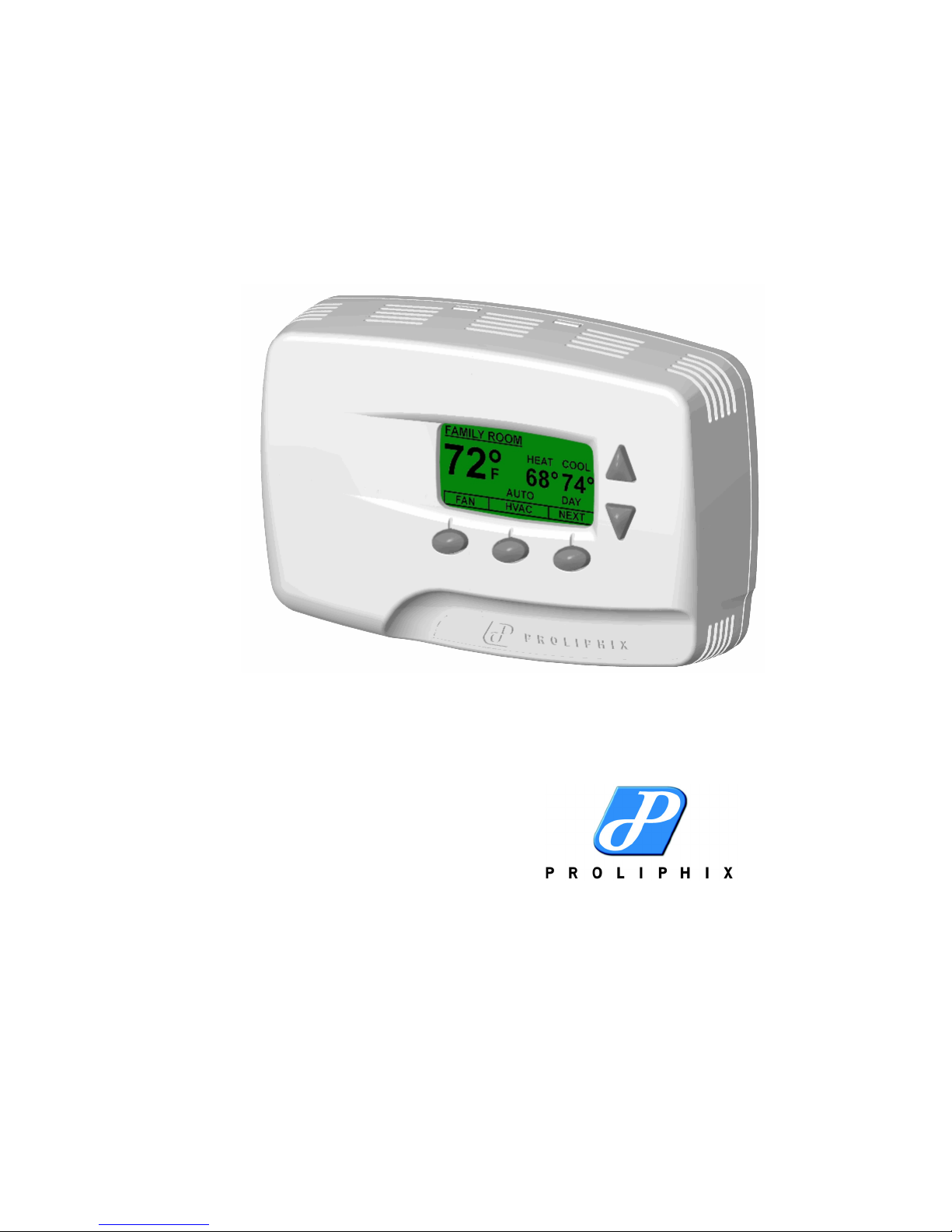
Proliphix Thermostat Installation Guide
Release 1.0
Part No. 600-01000-100
April 2006
Page 2

Beta Draft Confidential
Technical
Support
Warranty
Information
When contacting Proliphix for technical assistance, please have the following information available:
Product model and serial number.
Type of heating/cooling system (example: gas, oil, or electric; warm air, hot water, heat pump,
steam or gravity).
Location and number of wires attached to your Proliphix thermostat.
For additional assistance, please contact Proliphix Technical Support,
9:00 AM to 5:00 PM Eastern Standard Time Monday to Friday:
Web: www.proliphix.com
Email: [email protected]
Telephone: 1-866-IPLIVING
Fax: 978-692-3378
Proliphix, Inc. warrants its products to be free from manufacturing defects in materials and workmanship
under normal use for a period of 1 Year from the date of purchase for Professional Series thermostats and 90
Days from the date of purchase for Basic Series thermostats.
Proliphix shall not be liable to honor the terms of this warranty if the product has been used in any other
application other than that for which it was intended, or if it has been subjected to misuse, accidental damage,
modification, or improper installation procedures. Furthermore, this warranty covers only products which have
all original and unaltered markings and labels (serial numbers, model numbers, etc.) of manufacture.
This warranty shall be the sole and exclusive remedy to the original purchaser. In no event will Proliphix be
liable for incidental or consequential damages (including property and economic) of any kind arising from the
sale and use of this equipment. Proliphix is not liable for any claim made by a third party or made by a
purchaser for a third party.
Material
Return
Procedure
Proliphix, shall, at its option, repair or replace any product found defective, without charge for parts and labor.
Repaired or replaced equipment or parts supplied under this warranty shall be covered only by the unexpired
period of the warranty.
In no event shall Proliphix's liability exceed the price paid for the product from direct, indirect, special,
incidental, or consequential damages resulting from the use of the product, it's accompanying software, or its
documentation. Proliphix offers no refunds for its products.
Except as expressly set forth in this warranty, Proliphix makes no other warranties, expressed or implied, nor
authorizes any other party to offer any warranty, including any implied warranties of merchantability or fitness
for a particular purpose. Any implied warranties that may be imposed by law are limited by the terms of this
limited warranty. This warranty statement supersedes all previous warranties.
This warranty extends to products purchased directly from Proliphix or an authorized Proliphix dealer,
distributor or reseller.
No merchandise may be returned for credit, exchange, or service without prior authorization from Proliphix.
To obtain warranty service for Proliphix products, contact Proliphix Customer Service (1-866-IP-LIVING)
and request a Return Material Authorization (RMA) number.
Products may be returned for credit, exchange, or service with a Proliphix RMA number. Enclose a note
explaining the symptoms of the problem, stating the RMA number, and the name, address and phone number
of the company or individual contact.
Authorized returns must be shipped prepaid to Proliphix:
Proliphix, Inc.
Suite #1
66 Tadmuck Road
Westford, MA 01886
ii Proliphix Thermostat Installation Guide, Release 1.0
Part No. 600-01000-100
Page 3

Mark the RMA number on the outside of the package. Products received without an RMA number or without
shipping prepaid will be subject to refusal by Proliphix.
Return shipping charges following repair of items under warranty shall be paid by Proliphix via standard
ground carrier. In the event that repairs are found to be non-warranty, return shipping charges will be paid by
the purchaser.
FCC Model: NT10e/NT20e, NT100e/h, NT120e/h, NT125e/h, NT150e/h
Made in the USA
This device complies with Part 15 of the FCC Rules. Operation is subject to the following two conditions: (1)
this device may not cause harmful interference, and (2) this device must accept any interference received,
including interference that may cause undesired operation.
CSA Power: 24VAC 45mA 60Hz
48VDC 22mA 60Hz
Switched power each contact: 24VAC 2A 60Hz
Proliphix Thermostat Installation Guide, Release 1.0 iii
Part No. 600-01000-100
Page 4

Beta Draft Confidential
iv Proliphix Thermostat Installation Guide, Release 1.0
Part No. 600-01000-100
Page 5

Beta Draft Confidential
Overview
The Proliphix family of Network Thermostats (NT) provide a rich set of innovative
features including the ability to configure settings through a graphical interface either
locally or from any remote location. The thermostats can be connected via secure
wired Ethernet to a home, small business, or light commercial data network.
This guide describes how to physically install the basic series (NT10e/NT20e) as well
as the professional series of thermostats (NT100e/h, NT120e/h, NT125e/h, and
NT150e/h). Any instructions or guidelines that apply to a specific thermostat model
are noted within this guide. The following model-specific features are important to
note during the installation:
NT10e/NT20e (Basic Series)
Powered by Proliphix Ethernet Power Adapters (EPA20/60).
(NT20e only) Two remote thermal sensors; either Analog or Thermistor.
Single-stage HVAC (1h/1c).
Heat pump HVAC with auxiliary heat (2h/1c).
NT100e/h, NT120e/h, NT125e/h, and NT150e/h (Professional Series)
Powered by Proliphix Ethernet Power Adapters (EPA20/60) or Power over Ethernet (PoE, 802.3af)
power injector equipment. The “h” version models support HVAC system power with 24VAC.
Two remote thermal sensors; either Analog or Thermistor on the NT120e/h, NT125e/h, and
NT150e/h.
Dual-stage HVAC (2h/2c).
Heat pump HVAC with auxiliary heat (2h/1c).
Installing the Thermostat
This section describes the required tools, guidelines, and installation instructions for
all models of Proliphix thermostats.
Preventing electrostatic discharge (ESD) — Static electricity may cause damage
Caution
Required Tools
to the components on the thermostat’s circuit module. Do not remove the
thermostat from the protective bag until you are ready to install the thermostat.
The following tools are required to install the Proliphix thermostat:
#1 or #2 Phillips head screwdriver.
Drill with a 3/16” or 7/32” bit.
Proliphix Thermostat Installation Guide, Release 1.0 1
Part No. 600-01000-100
Page 6

Installing the Thermostat
Installation Guidelines
Use the following guidelines to install the Proliphix thermostat:
If you are replacing an existing thermostat, mount the Proliphix thermostat in the
Tip
same location as the thermostat in which you are replacing.
Install the thermostat on an inside wall, about 5 feet (1.5m) above the floor, and in
a room that is used often.
Install the CAT5/CAT5E/CAT6 cabling from the wiring center to the thermostat
installation site.
Install the thermostat in an area or room with adequate air circulation and where
there are no unusual heating/cooling conditions, such as: sunlight, near a lamp,
radio, television, radiator register, or fireplace; near hot water pipes in a wall; near
a stove on the other side of the wall, on a wall separating an unheated room; or in
a draft from a stairwell, door, or window; in a corner or alcove; or behind an open
door.
Beta Draft Confidential
Caution
Install the unit after all construction work and painting is complete.
Install the unit in an unobstructed location where there are no objects on the wall
above or below the thermostat or other obstructions (such as furniture) restricting
vertical airflow.
It is not necessary for the thermostat to be level.
Prior to installing or servicing the thermostat, turn off electricity to the HVAC
system; do not turn electricity back on until all work is complete.
Do not jumper wires together to test the system. This may cause harm to your
HVAC system and damage the thermostat, and therefore void the warranty.
All wiring must conform to local codes and ordinances. The distance between
CAT5/CAT5E/6 cables and HVAC cables should be a minimum of one inch.
2 Proliphix Thermostat Installation Guide, Release 1.0
Part No. 600-01000-100
Page 7

Beta Draft Confidential
Before You Begin
If you are removing an existing thermostat, Proliphix recommends that you label each
connection as you remove the wiring. You will use these same wires (and labels) when
you connect the Proliphix thermostat (page 4).
Use the following steps to remove an existing thermostat:
1 Turn off power to the HVAC system or the fuse/circuit breaker panel.
2 Remove the cover from the existing thermostat. If the cover does not snap off when
pulled firmly from the top or bottom, check for a screw(s) that may be used to secure
the cover.
3 Disconnect each wire. Label the wires with the terminal designation from the existing
thermostat. Place the label about 1/2” away from the end of the wire to allow for
stripping of the ends. Note: If this is a new installation, obtain the wire designations
from the HVAC installer.
4 Remove the existing thermostat from the wall.
Before You Begin
Installing and Wiring the Thermostat
This section describes a two-step installation process in which you install (or mount)
the thermostat base plate and wire the thermostat.
Installing the Base Plate
Perform the following steps to mount the thermostat base plate on the wall:
1 Review the Installation Guidelines on page 2 and position the base plate in an
appropriate location on the wall. Ensure the location allows you to access and pull the
wires through the opening in the base plate.
2 Using a pencil, mark the center of the screw holes on the left and right side, and
bottom center of the base plate.
3 Remove the base plate from the wall and drill three holes at the marked locations: for
drywall, drill 3/16” holes; for plaster, drill 7/32” holes.
4 Gently tap the wall anchors (included in the packaging) into the drilled holes until
they are flush with the wall.
5 Pull the wires through the base plate and position the base plate over the screw holes.
6 Attach the base plate to the wall using three 1" screws (included in the packaging).
Proliphix Thermostat Installation Guide, Release 1.0 3
Part No. 600-01000-100
Page 8

Installing and Wiring the Thermostat
Wiring the Base Plate Terminals
Use the instructions in this section to wire the base plate terminals as follows:
Wire the NT10e/NT20e base plate for fuel burner HVAC (page 4) and heat pump
HVAC (page 6).
Wire the NT100e/h, NT120e/h, NT125e/h, and NT150e/h for fuel burner HVAC
(page 4) and heat pump HVAC (page 6).
Fuel Burner HVAC
Use the instructions in this section and refer to Table 1 and Figure 1 to wire the base
plate for fuel burner HVAC. Refer to the labels you placed on the wires when you
removed the existing thermostat (page 2).
Table 1 lists the standard HVAC terminal label and the corresponding Proliphix label
required to support the single-stage and dual-stage application.
Table 1 Fuel Burner Terminal Conversion Chart
Beta Draft Confidential
Standard
Terminal
R, RH RH 24VAC source 24VAC source
RC RC 24VAC source 24VAC source
CCNot used
W, W1 W1 Heat relay Stage 1 heat relay
Y, Y1 Y1 Cool relay Stage 1 cool relay
W2 W2 Not used Stage 2 heat relay
Y2 Y2 Not used Stage 2 cool relay
G G Fan relay Fan relay
- S1+ or
- H Not used Contact closure, Active open or Active closed
a
For “h” thermostat models only, the 24VAC common must be in the same AC phase as the 24VAC
source (RH or RC). If the thermostat is connected to RH only, or RH and RC then C must be the RH
common. If the thermostat is connected to RC only then C must be the RC common.
Proliphix
Terminal
CM
NT10e/NT20e NT100e/h, NT120e/h, NT125e/h,
and NT150e/h
Not used or 24VAC common
Not used Contact closure common (NT150 only)
(NT150 only)
a
4 Proliphix Thermostat Installation Guide, Release 1.0
Part No. 600-01000-100
Page 9
Beta Draft Confidential
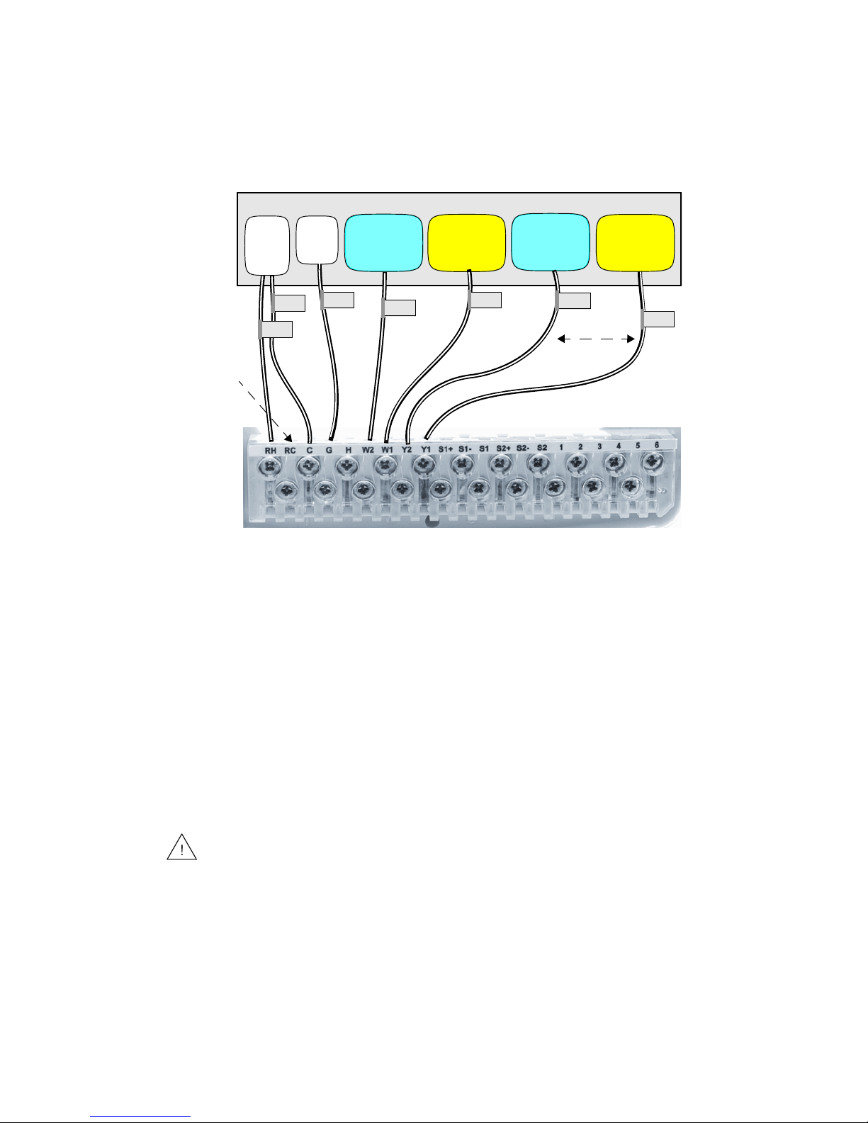
Figure 1 shows an example of a single-stage (shown in yellow) and dual-stage (shown
in blue) HVAC system connecting to a Proliphix base plate.
Figure 1 Single/Dual Stage HVAC Connections
HVAC System
Installing and Wiring the Thermostat
RH
C
Fan
Control
1
2nd Stage
Heat Control
G
1st Stage
Heat Control
W2
Proliphix Base Plate
Cool &
Heat
Power
Square Hole
1.
Applies to “h” models only
1 Use Ta ble 1 to match the letter of your existing thermostat wire to the corresponding
W1
2nd Stage
Cool Control
Y2
1st Stage
Cool Control
Y1
Wire
terminal letter on the Proliphix base plate.
2 Strip the wire insulation 3/8” (9.5 mm) from the wire ends. Verify that the wire ends
are straight. To avoid damaging the labels, use caution when handling the wires and
push any excess wire back into the wall.
3 Using Figure 1 as a guide, connect the labeled wires to the terminal post with the
corresponding letter on the Proliphix base plate. For example, connect the wire
labeled “W1” to the W1 terminal post.
If necessary, unscrew the terminal post screw used to secure the wires. Insert the wire
straight down into the square hole and secure the corresponding screw to the wire.
To avoid damage to the Proliphix base plate, stop unscrewing the terminal post
Caution
screws when you feel a slight stop or resistance.
4 Verify that the wire is securely attached to the terminal post in the base plate by gently
tugging on the wire.
Proliphix Thermostat Installation Guide, Release 1.0 5
Part No. 600-01000-100
Page 10

Installing and Wiring the Thermostat
Heat Pump HVAC
Use the instructions in this section to wire the base plate terminals for heat pump
HVAC on all models of Proliphix thermostats.
You must know the type of Reverse Valve (RVS) in your heat pump. See the user
Note
manual for your heat pump for more information.
To wire the base plate terminals for heat pump HVAC on the Proliphix thermostat,
refer to the labels you placed on the wires when you removed the existing thermostat
(page 2). Refer to the procedure in Fuel Burner HVAC and use Table 2 and Figure 2
to complete the wiring.
Table 2 lists the standard HVAC terminal label and the corresponding Proliphix label
required to support the heat pump application.
Table 2 Heat Pump Terminal Conversion Chart
Beta Draft Confidential
Standard
Terminal
R, RH RH 24VAC source 24VAC source
RC RC 24VAC source 24VAC source
CCNot used
W, W1 W1 Auxiliary heat relay Auxiliary heat relay
Y, Y1 Y1 Compressor relay Compressor relay
B W2 RVS activate for heat relay RVS activate for heat relay
O Y2 RVS activate for cool relay RVS activate for cool relay
G G Fan relay Fan relay
- S1+ or
- H Not used Contact closure, Active open or Active
a
For “h” thermostat models only, the 24VAC common must be in the same AC phase as the
24VAC source (RH or RC). If the thermostat is connected to RH only, or RH and RC then C must
be the RH common. If the thermostat is connected to RC only then C must be the RC common.
Proliphix
Terminal
CM
NT10e/NT20e NT100e/h, NT120e/h, NT125e/h and
NT150e/h
Not used or 24VAC common
Not used Contact closure common (NT150 only)
closed (NT150 only)
a
6 Proliphix Thermostat Installation Guide, Release 1.0
Part No. 600-01000-100
Page 11
Beta Draft Confidential
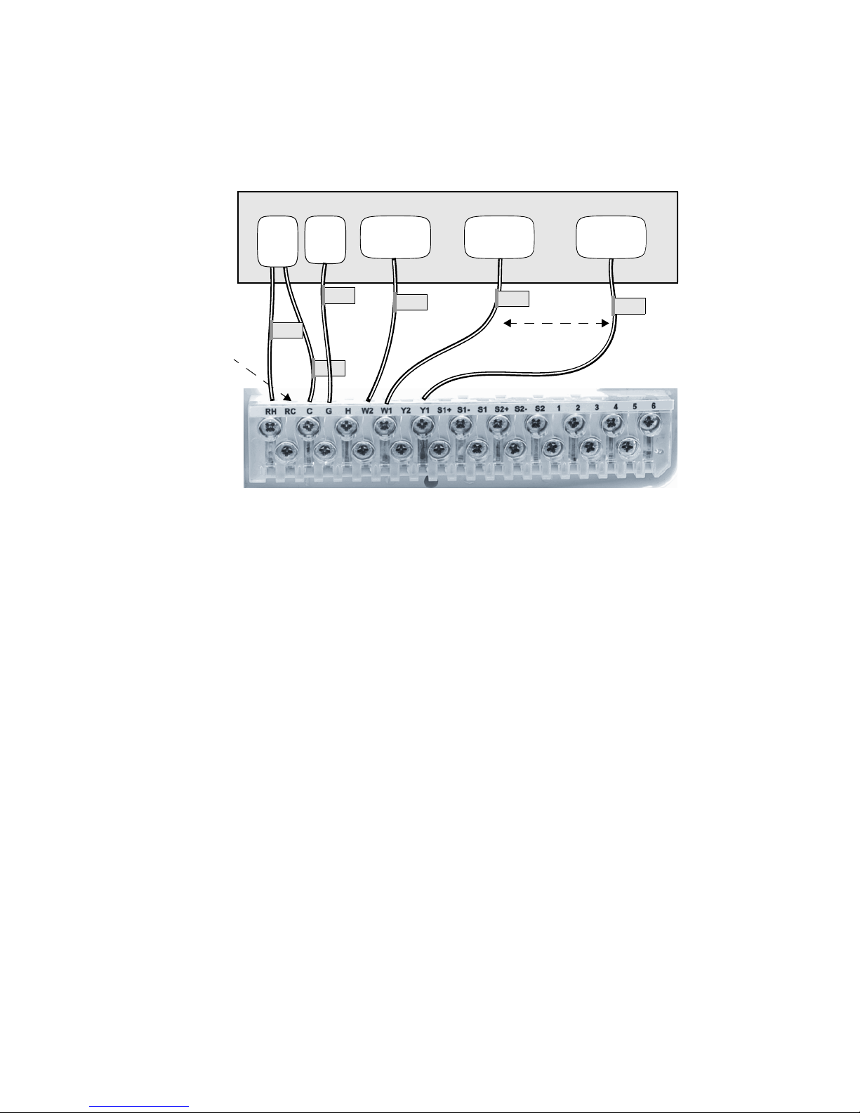
Figure 2 shows an example of a heat pump HVAC system, with reverse activate for
heat, connecting to a Proliphix base plate.
Figure 2 Heat Pump HVAC Connections
HVAC System
Installing and Wiring the Thermostat
Cool &
Heat
Power
Square Hole
1.
Applies to “h” models only
Note: A heat pump is either a reverse for heat or reverse for cool model. Y2 (not shown in Figure 2)
is used for reverse cool.
Fan
Control
RH
C
1
G
Reverse for
Heat
W2
Proliphix Base Plate
Auxiliary
Heat
W1
Compressor
Y1
Wire
Configuring Remote Sensors for the NT20, NT120, NT125, and
NT150
The Proliphix thermostat provides two remote (external) sensor ports. This release
supports Analog and Thermistor sensors (go to Proliphix.com for a complete list of
supported sensors).
Analog sensors convert temperature measurements as Fahrenheit degrees to a voltage
which can be sensed by the thermostat. Analog sensors are active devices which
require power from the thermostat. The Analog sensor is polarized and must be
connected as shown in Table 3.
Thermistor sensors are passive devices which represent thermal measurements as
electrical resistance. Thermistors do not require power from the thermostat. The
Thermistor sensor is not polarized; either lead can be connected as shown in Table 3.
Proliphix Thermostat Installation Guide, Release 1.0 7
Part No. 600-01000-100
Page 12

Installing and Wiring the Thermostat
Table 3 lists the external sensor port Analog and Thermistor connections. Only one
sensor can be connected to each port.
Table 3 Remote Sensor Port Connections
Beta Draft Confidential
Proliphix
Terminal
S1+ Do Not Use or Do Not Use
S1- COM or Sensor 1, Either lead
S1 T20 or Sensor 1, Either lead
S2+ or S+ +V for S1 and S2 Do not use
S2- COM or Sensor 2, Either lead
S2 T20 or Sensor 2, Either lead
a
Do not connect either lead to the S1+, S2+ or S+ terminal when using a
Thermistor sensor.
Analog Sensor
Thermistor Sensor
Connecting CAT5/CAT5E/6 Wiring for Ethernet Networks
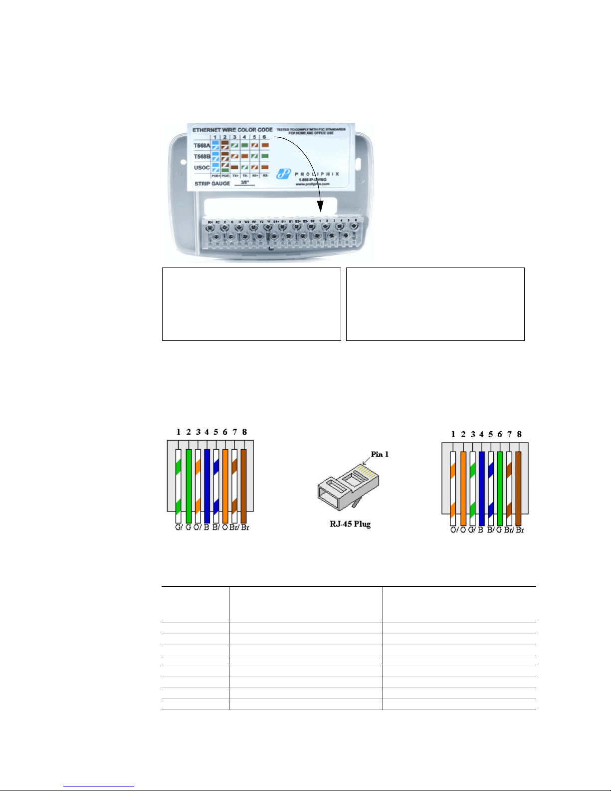
The label located on the inside of the base plate (see Figure 3) shows several
color-coded wiring schemes for Ethernet CAT5/CAT5E/6 connections.
To wire the Ethernet network, refer to Figure 3 and match the label number to the
Proliphix base plate number for CAT5/CAT5E/6 color coding.
a
If the other end of the CAT5/CAT5E/6 cable is connected to a Proliphix EPA-20/60
Note
Ethernet Power Adapter, follow the wiring scheme for T568A.
All wiring must conform to local codes and ordinances. The distance between
Caution
8 Proliphix Thermostat Installation Guide, Release 1.0
CAT5/CAT5E/6 cables and HVAC cables should be a minimum of one inch.
Part No. 600-01000-100
Page 13
Beta Draft Confidential
Figure 3 shows an Ethernet CAT 5 wiring example.
Figure 3 Ethernet CAT5/CAT5E/6 Wiring
Installing and Wiring the Thermostat
T568A
1 White-blue and blue ends stripped and twisted
2 White-brown and brown ends stripped and twisted
3 White-green
4 Green
5 White-orange
6 Orange
T568B
1 White-blue and blue ends stripped and twisted
2 White-brown and brown ends stripped and twisted
3White-orange
4 Orange
5White-green
6 Green
Figure 4 shows the RJ-45 Ethernet plug pinout assignments for the T568A and T568B
wiring standards.
Figure 4 RJ-45 Ethernet Plug Pinout Assignments for T568A and T568B
T568A T568B
Table 4 describes the pinout assignments for the T568A and T568B wiring standards.
Table 4 T568A and T568B Pinout Assignments
Pin Number T568A Wire Color T568B Wire Color
1 Green/White Orange/White
2 Green Orange
3 Orange/White Green/White
4 Blue Blue
5 Blue/White Blue/White
6 Orange Green
7 Brown/White Brown/White
8 Brown Brown
Proliphix Thermostat Installation Guide, Release 1.0 9
Part No. 600-01000-100
Page 14

Beta Draft Confidential
Installing and Wiring the Thermostat
Mounting the Thermostat into the Base Plate
The Proliphix thermostat contains jumpers to configure the HVAC power settings.
The power settings determine which HVAC power source (RH or RC) is configured to
turn on each HVAC system (cool, heat and fan). Most applications use only RH
power. The Proliphix thermostat is shipped from the factory with the “RH Only”
configuration.
Table 5 lists the possible HVAC power configurations. RC and RH are connected with
J1 inserted.
Table 5 HVAC Power Configuration
HVAC Power Configuration J2 J1
RH only (default) – Supplies W1, W2, Y1, Y2, G POS1 IN
RC only – Supplies W1, W2, Y1, Y2, G POS1 IN
RH and RC – RH supplies W1, W2, G and RC supplies Y1
and Y2
RH and RC – RH supplies W1 and W2 and RC supplies Y1,
Y2, G
POS1 OUT
POS2 OUT
The NT100e/NT120e/NT125e can be powered from different sources presented on the
following Ethernet CAT5/5E/6 interface:
A Power over Ethernet (PoE) source is an Ethernet router, switch, or mid-span
device that complies with the 802.3af Power over Ethernet standard.
Proliphix Ethernet Power Adapters (EPA) are multi-port power injectors capable
of supplying power to either two (EPA-20) or six (EPA-60) Proliphix Network
Thermostats.
Table 6 shows how to configure the NT100e/NT120e/NT125e for two different power
sources.
Table 6 NT100e/NT120e/NT125e Power Source Configuration
HVAC Power Configuration J3
PoE Power Source Out
EPA-20/60 Power Source In
Figure 5 shows the location of the jumpers on the thermostat circuit module. The
jumper in J2 supports an Up (POS1) or Down (POS2) position. The example in
Figure 5 shows the J2 jumper in the Up position. If necessary, move the jumper
downward to the POS2 position.
10 Proliphix Thermostat Installation Guide, Release 1.0
Part No. 600-01000-100
Page 15

Beta Draft Confidential
Figure 5 Thermostat Jumper Locations
Installing and Wiring the Thermostat
J3
Prior to mounting the thermostat into the base plate, verify that the jumpers on the
thermostat are configured for your application (see Table 5).
To mount the thermostat into the base plate:
1 Mount the thermostat into the base plate (see page 3) by inserting the top two hinges
into the corresponding receptacle holes in the top of the base plate.
2 Snap the bottom of the thermostat securely into the base plate.
Verifying the Thermostat’s Operating Status
This section describes the procedures you can use to verify that the heat, cool, and fan
controls are operating properly on your thermostat. Before you begin, verify that the
HVAC system’s power is set to “On” and press HVAC on the thermostat panel.
Testing the Heat Controls
1 Press HVAC.
2 Press Mode. A menu list appears.
3 Use the Up and Down arrows on the right side of the panel to select Heat.
4 Press Select.
5 Press Back.
6 Continuously press the Up arrow until the heat set point is higher than the temperature
reading. The heat relay should click and the HVAC system should activate the heat.
Proliphix Thermostat Installation Guide, Release 1.0 11
Part No. 600-01000-100
Page 16

Installing and Wiring the Thermostat
Testing the Cool Controls
1 Press HVAC.
2 Press Mode. A menu list appears.
3 Use the Up and Down arrows on the right side of the panel to select Cool.
4 Press Select.
5 Press Back.
6 Continuously press the Down arrow until the cool set point is lower than the
temperature reading. The cool and fan relays should click and the HVAC system
should activate the cool and fan.
Testing the Fan Operation
1 Press HVAC.
2 Press Fan. A menu list appears.
3 Use the Up and Down arrows on the right side of the panel to select On.
Beta Draft Confidential
4 Press Select. The fan relay should click and the fan should turn on.
12 Proliphix Thermostat Installation Guide, Release 1.0
Part No. 600-01000-100
Page 17

Beta Draft Confidential
Troubleshooting
Use Table 7 to troubleshoot potential issues with your thermostat.
Table 7 Troubleshooting Tips
Condition Possible Cause
LCD display is blank If using a Proliphix EPA to power your thermostat:
Check power to the EPA.
Check the wiring on the EPA punchdown terminal (use the T568A wiring scheme).
Use a 110 block punchdown tool to ensure proper connection.
Check the blue and brown pairs on the Ethernet cable connected on screw terminals 1 and
2.
Verify that jumper J3 is on both pins (In position)
If using PoE to power your thermostat:
Verify that jumper J3 is not connected to both pins (Out position).
Verify the PoE equipment is sending power to the thermostat. See your PoE equipment
documentation.
Verify that Ethernet wiring is securely attached to terminal screws.
If using an “h” model thermostat:
Verify that the Common from the primary transformer source (either RH or RC) is
connected to the C terminal.
Either RH or RC (24v source) must be connected.
Verify the HVAC system is powered on.
Installing and Wiring the Thermostat
LCD display is active but no
network link indication exists
HVAC heat does not activate
when tested
HVAC cool does not activate
when tested
HVAC fan does not activate
when tested
After you install the thermostat, continue with the Remote Management Guide and the
Configuration Guide to manage the thermostat locally or remotely and configure
thermostat settings.
If using a Proliphix EPA to power your thermostat:
Check the wiring on the EPA punchdown terminal (use the T568A wiring scheme).
Use a 110 block punchdown tool to ensure proper connection.
Verify that the Ethernet patch cable is in the correct RJ45 port of the EPA (port 1 connects
to punchdown 1, etc.)
Verify that the Ethernet patch cable is connected to a working hub, switch, or router.
Verify you increased the heat set point higher than the temperature reading and the
thermostat is in heat mode (see page 11).
Verify the HVAC system is powered on (page 11).
Verify you decreased the cool set point lower than the temperature reading and the
thermostat is in cool mode (see page 12).
Verify the HVAC system is powered on (page 11).
Check the base plate wiring (see page 4 or page 6).
Verify the HVAC system is powered on (page 11).
Proliphix Thermostat Installation Guide, Release 1.0 13
Part No. 600-01000-100
Page 18

Installing and Wiring the Thermostat
Beta Draft Confidential
14 Proliphix Thermostat Installation Guide, Release 1.0
Part No. 600-01000-100
 Loading...