

Page 1

USER'S Manual
Version 2.0
Hurricane 8800
ADSL Bridge/Router
Page 2

1
Contents
Section One - Introduction ......................................................................... 3
1.1 System Requirements .............................................................................................................3
1.2 Features Summary ..................................................................................................................3
1.3 Equipment Performance ........................................................................................................4
1.3.1 ATM layer ..................................................................................................................4
1.3.2 Protocols ...................................................................................................................4
Section Two - Connect the Bridge/Router .................................................. 6
2.1 T his Package contents ............................................................................................................6
2.2 Product View ...........................................................................................................................7
2.3 Hardware Installation ............................................................................................................8
2.4 Network Connections ...........................................................................................................9
2.4 .1 for four PCs ..........................................................................................................................9
2.4 .2 for more than four PCs .....................................................................................................9
Section Three - Configure the PCs .......................................................... 10
3.1 specify an static IP for your computer. ............................................................................10
3.2 Verify the link between your PC and Router ................................................................12
Section Four - Configure t he Bridge/Router ............................................ 13
4.1 . Description of Web configuration. ...................................................................................13
4.2 . How to Configure your router .........................................................................................14
4.2.1 PPPoA Routed Configuration. ..........................................................................16
4.2.2 PPPoE Routed Configuration. ...........................................................................20
4.2.3 RFC 1 483 Routed Configuration. .....................................................................23
4.2.4 IPoA Routed Configuration. ...............................................................................26
4.3 How to Configure DHCP Server. ....................................................................................27
4.4 How to set Port Forwarding. .............................................................................................28
4.5 How to let Netmeeting pass through. ...........................................................................29
4.6 How to Configure Bridge Mode.......................................................................................30
4.7 How to Restore to the Factory Default. ........................................................................31
Appendix A - Troubleshooting .................................................................. 32
Appendix B - High Protocols..................................................................... 34
Appendix C - Acronyms ............................................................................ 37
Appendix D - EMC and Safety .................................................................. 38
Appendix E- Telecom Notices ................................................................... 39
Page 3

2
The information contained in this manual has be en verified at the time of this manual's
prin ting. The manufacturer reserves the right to make any changes and improvements
in the product described in this manual at any time and without notice.
All registered trademarks are the property of the ir respective owners.
Copyright © 2002 All rights reserved. No reproduction of this document in any form
is permitted without prior written authorization from the manufacturer.
Page 4

3
Section One - Introduction
The Hurricane 8800 provides Full rate (ANSI and G.DMT) as well as G.lite
ADSL standards line support, and can be connected to PC through Ethernet.
This product supports bridge feature set for the integration of ADSL service
into corpor ate or home LAN and WAN.
1.1 System Requirements
Before connecting the Hurricane 8800 to your PC, make sure your sysytem
is equipped with the Ethernet NIC card and TCP/IP protocol.
1.2 Features Summary
ADSL S upport • ANSI ( T1.413 Iss ue 2 )
• G.dm t ( ITU G.992.1 )
• G.lite ( ITU G.992.2 )
• G.hs ( ITU G.994.1 )
• Power cutback (G.lite only )
LAN Support • IEEE 802.3 10/100 Base-T band CS MA/CD
ATM Support • ATM signaling UNI 3.1& 4.0
• Multi ple Protocol over AAL5 (RFC 1483 )
• AAL0, AAL2, AAL5
• VC and LLC based Multipl exing
• ATM S ervice Class: UBR/VBR/CBR
• VCs
Bridging Support • Trans parent bridging(RFC 1483) support
Section One: Introduction
Page 5

4
Section One: Introduction
1.3 Equipm ent Performance
1.3.1 ATM layer
The equipment will be fully compatible with the showed on the figure 1of
the ANSI T1.413-1998
1. Adaptation layer
The modem will implement the adaptation layer AAL5, as requested by the
recommendation ITU I.363.5
2. VCs
Support for non-zero VPIs is limit to PVCs only.The full VPI range(0~4095)
is supported.The full VCI range(1~65536) is supported. Low-numbered
VCIs on VPI0 are looked up.
3. Servi ce class
The modem will support : CBR,UBR,rt-VBR,nrt-VBR
4. OAM streams
The modem supports OAM F5 s tream.
5. ATM signaling & ILMI
The modem suppor ts ATM Formun UNI 3.0,3.1,UNI4.0& IISP signaling
bas ed on UNI3.0 or UNI3.1 using SSCOP as a data transport.The
implementation of ILMI is based on the ATM Forum's ILMI v4.0 specification.
1.3.2 Protocols
1. Br idge
It provides a tr ansparent and a spanning-tree bridge.
2. RFC 1483 br idged
The RFC in use i s the 2684, , the 1483 and 2684 are admitted for LLC
encaps ulation and VC multiplexing for bridged traffic.
Page 6

5
3. PPPoE relay
It is used to transport P PP traffic over Ethernet.
4. PPPoEthernet client (RFC 2516)
Authentifi cation is supported by PAP & CHAP protocols. The RFC 2516
supports for multiple PVCs,with each VC suppo rting a single PPPoE session
(different ISPs over differ ent PVCs)
5. BO OTP/TFTP client
Systems can be booted over Ethernet using BOOTP/TFTP. Once there is
a running image on the ASSP, the images and/or configuration stored in flash
can be updated using TFTP.
6. TELNE T server
The modem provides a sim ple telnet server that allows administrative
acces s to the platform over TCP/IP. The implementation supports only a
single session at a time.
Section One: Introduction
Page 7

6
Section Two: Connect th e Bridge/Router
Section Two - Connec t the Bridge/Router
2.1 This Package contents
1. ADS L Bridge/Router
2. RJ-45 straight cable
3. RJ-11 telephone cable
4. RS-232 cable
5. 5V DC Power Adaptor
6. CD with Configuration Tools
7. User's Manual
For any missing items, Please contact your dealer immediately.
1.
2
3
4
5.
6. & 7.
Page 8

7
Power LED (In red color)
Light ON once detected.
ADSL LED (In green color)
Light ON when the connection is ON.
LAN LED (In green color)
Keeps on, Light blinks during data
transfer
2.2 Product View
Line Jack
For RJ-11, to connect to ADSL Line
Power Connector
LAN Connectors
For RJ-45, to connect to PCs /HUB
Console Port
For RS-232, to connect to Serial Port
Reset Button
Section Two: Connect th e Bridge/Router
Page 9

8
2.3 Hardware Installation
The following steps instruct you to install the Hurricane 8800P for one
com puter. for more than four computers, please refer to 2.4 Network
Connecti on.
1. Turn off the com puter.
2. Plug the end of the Ether net cable into any one connector marked
at the back of the router.
3. Plug the other end of the Ethernet cable into your computer's RJ45 jack
of Ethernet card.
4. Connect the AC Power adaptor to the Jack.
5. Plug the telephone cable into the connector marked at the back of
the router.
6. Plug the other end of the telephone cable into a Phone Socket .
Section Two: Connect th e Bridge/Router
Power Adaptor
Micro filter
RJ-11 Cable
Strai ght RJ-45 Cable
Main Phone Socket
Page 10

9
2.4 Network Connections
2.4 .1 for four PCs
2.4.2 for m ore than four PCs
Section Two: C onnect the Bridge/Router
ADSL
RJ-11
RJ-45
ADSL
RJ-11
RJ-45
HUB/S WITCH
RJ-45
Straight Cable to Uplink port
or Cross Cable to normal port
Page 11

10
Section Three - Configure the PCs
The ins tructions in this section will help you configure each of your
computers to be able to communicate with the Router.
To do this, you need to configure your PC’s network settings to obtain an
IP address or get it automatically from the DHCP of the router. Computers
use IP addresses to communicate with each other across a network, such
as the Internet.
3.1 specify an static IP for your com puter.
•Set IP Address to 192.168.101.X (X:2~254)
•Set S ubnet Mask to 255.255.255.0
•Add Gateway to 192.168.101.1
•DNS Ser ver to Local DNS (e.g. 165.21.83.88)
For Windows 95/98/ME
Control Panel >Network>TCP/IP of your LAN card
Section Three: Configure the PCs
Page 12

11
For Windows XP
1. Click the Start button and then Control Panel. From there, click the
Network and Internet Connections icon. Then click the Network
Connections i con.
2.Select the Local Area Connection icon for the appli cable Ethernet
adapter Doubl e-click the Local Area Connection. Click the Properties
button.
Sect ion Three: Configure the PCs
Page 13

12
3.2 Verify the link between your PC and Router
a) From start > Run
b) Enter ping 192.168.101.1 –t and click OK
c) If the connection has been established, You will r eceive reply from
the router.
d) If you receive “Request timed out”, that means the link has not been
establis hed, pls. check the network cable and IP address.
NOTES:
1. You may have to disable the proxy settings on your Internet
browser . Tools>Internet Options>Connection>LAN settings>
Disable Proxy Server
2. Make sure that your browser is set to connect directly .
For Inter net Explorer, click Tools, Internet Options, and then the
Connection tab. Make sure that Internet Explorer is set to Never dial a
connection.
For Netscape Navigator, cl ick Edit, Preferences, Advanced, and Proxy
Make s ure that Netscape Navigator is set to Direct connection to the
Internet.
Section Three: Configure the PCs
Page 14

13
Section Four: Configure th e Bridge/Router
Section Four - Configure the Bridge/Router
4.1. Description of Web configuration.
1)Open Internet E xplorer , type http://192.168.101.1
2)The s ystem will remind you to enter administrator’s username and
password when restarting or configuring. It is illustrated in the following
figure.
Default userna me: admin
password: admin
Page 15

14
3)Ther e are four main menus in the left column:
“Status” to the curr ent status of every setting, including IP of
port, connecti on status of port, and status of WAN port, LAN
port, hardware and definition port.
“System” to show informati on of the ADSL Router, including
Error Log, Up grade and Restart (to factory default)
“Configuration” to s et the parameters according to your
operating system.
• Save Config to click Save button and wait until it fi nishes.
• Authentication to check current user information and create
new user.
• LAN Connection to change default LAN port addr ess.
• WAN Connection to check, edi t and delete current WAN
port configuration or create new routing mode and bridging
mode .
• SNTP Client to set SNTP (Simple Network Time Protocol)
• Secur ity to set NAT, Port forwarding, DMZ and firewall .
“ADSL” to check the attribution of ADSL l evel.
4.2. How to Configure your router
You can configur e your router as either one of the following modes:
Routing mode
ü RFC 1483 Routed
ü PPPoE Routed
ü IPoA Routed
ü PPPoA Routed
Section Four: Configure t he Bridge/Router
Page 16

15
Bridging mode
ü RFC 1483 Bri dged
ü PPPoE Relay Bridged
Please kindly check with your local ISP, select one of the above modes to
configure it.
The Information i n the screen shots in this manual is as examples
only, you are required to replace these values wi th those provided
by your ADSL Internet Service Provider or your System
Administrator!
NOTE : You have to delete the existent wan connection before
configuring a new one.
1) SingNet and Pacific Internet : PPPoA or PPPoE
2) M agix ATM plan(Static IP) : RFC 1483 Routed
Section Four: Configure th e Bridge/Router
Page 17

16
4.2.1 PPPoA Routed Configuration.
A. Click Router mode under Configuration and choose PPPOA routed.
Click Configure and the interface shows as below.
Section Four: Configure t he Bridge/Router
Page 18

17
• Description: Name of the WAN connection. (e.g. Si ngNet
• VPI/VCI: ATM VC of local ISP (rem ote)
(e.g. for Singapore, VP I=0 , VCI=100)
• WAN IP Address/WAN Subnet Mask: IP and Subnet Mask
dynami cally allocated by your ISP.
0.0.0.0 (Default)
255.255.255.0 (Default)
• LLC Header Mode: off (Default)
• HDLC Header M ode: off (Default)
• Choose CHAP
• User name and Password: The user name and password will
be provided by your ISP when applying for ADSL service. (e.g.
prolink@singnet )
Click Configure to compl ete
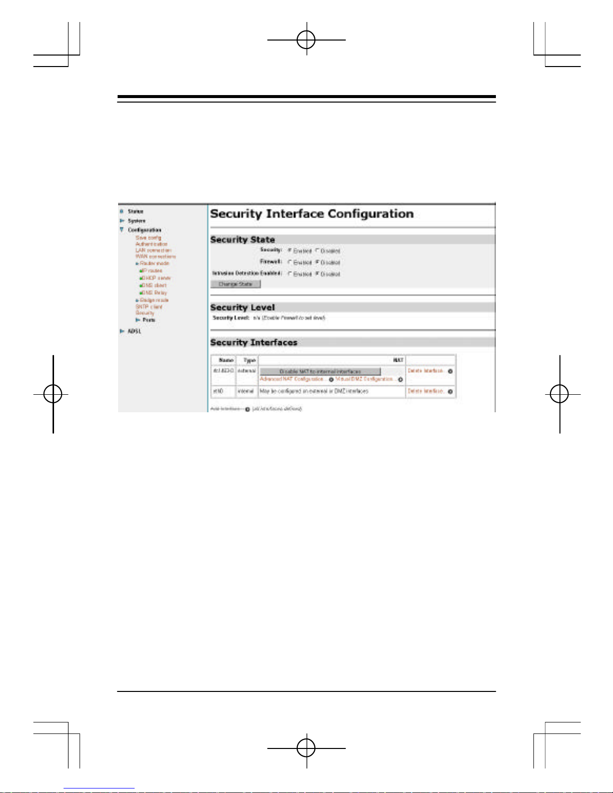
B. NAT Configuration.
Cl ick Security and the interface shows as below. Choose Enable under
Security State and click Change State
Section Four: Configure th e Bridge/Router
Page 19

18
Click add Interface und er Security Interface
Add WAN Interface
•Name : select the name of WAN Port (e.g. ppp-0)
•Interface Type : Choos e external
Click Apply and WAN Interface is added.
Add LAN Interface
•Name: Sel ect the name of LAN port (e.g. eth0 or ip1)
•Interface Type: Choose internal
Click Apply and LAN Interface is added. The screen will show the following
interface.
Section Four: Configure t he Bridge/Router
Page 20

19
Click Enable NAT to internal interfaces a nd the configuration of PPPoA
Router mode has been done.
NOTE: Please remember to save the configuration after finishing
the settings.
Section Four: Configure th e Bridge/Router
Page 21

20
Click Save Config , then Click Save button and wait until it finishes.
4.2.2 PPPoE Routed Configuration.
A. Click Router mode under Configuration and choose PPPOE routed.
Section Four: Configure t he Bridge/Router
Page 22

21
Click Configure and the interface shows as below.
• Description: Nam e of the WAN connection (e.g. SingNet)
• VPI/VCI: ATM VC of local ISP (remote). e.g. for Singapore
VPI=0 , VCI=100
• PPPoE Auto Connect: Default as Disabled (‘Enable’ means
starti ng using. Its function is: ADSL automatically disconnects
when the time without data transmission in LAN port equals to
the time set in “User Idle Time Out”.ADSL automatically
connects when there is data transmi ssion again)
• WAN IP Address/WAN Subnet Mask : IP and Subnet Mask
dynam ically allocated by ISP.
0.0.0.0 (Default)
255.255.255.0 (Default)
• Access Concentrator: Blank (Default)
• Service Name: Blank (Default)
• Host Unique Tag (in hex): Blank (Default)
Section Four: Configure th e Bridge/Router
Page 23

22
• LLC Header Mode: Off (Default)
• HDLC Header M ode: Off (Default)
• Choose CHAP
• User name and Password: The user name and password will
be pr ovided by ISP when applying for ADSL service
• User Idle Timeout (in minutes) Refer to description of PPPoE
Auto Connect
Click Configuration to compl ete
B. NAT Configuration.
Confi guration of NAT is the same as that of PPPoA Router mode, Please
refer to 4.2.1.B.(Page 17-20)
NOTE: Please remember to save the configuration after finishing
the settings.
Section Four: Configure t he Bridge/Router
Page 24
23
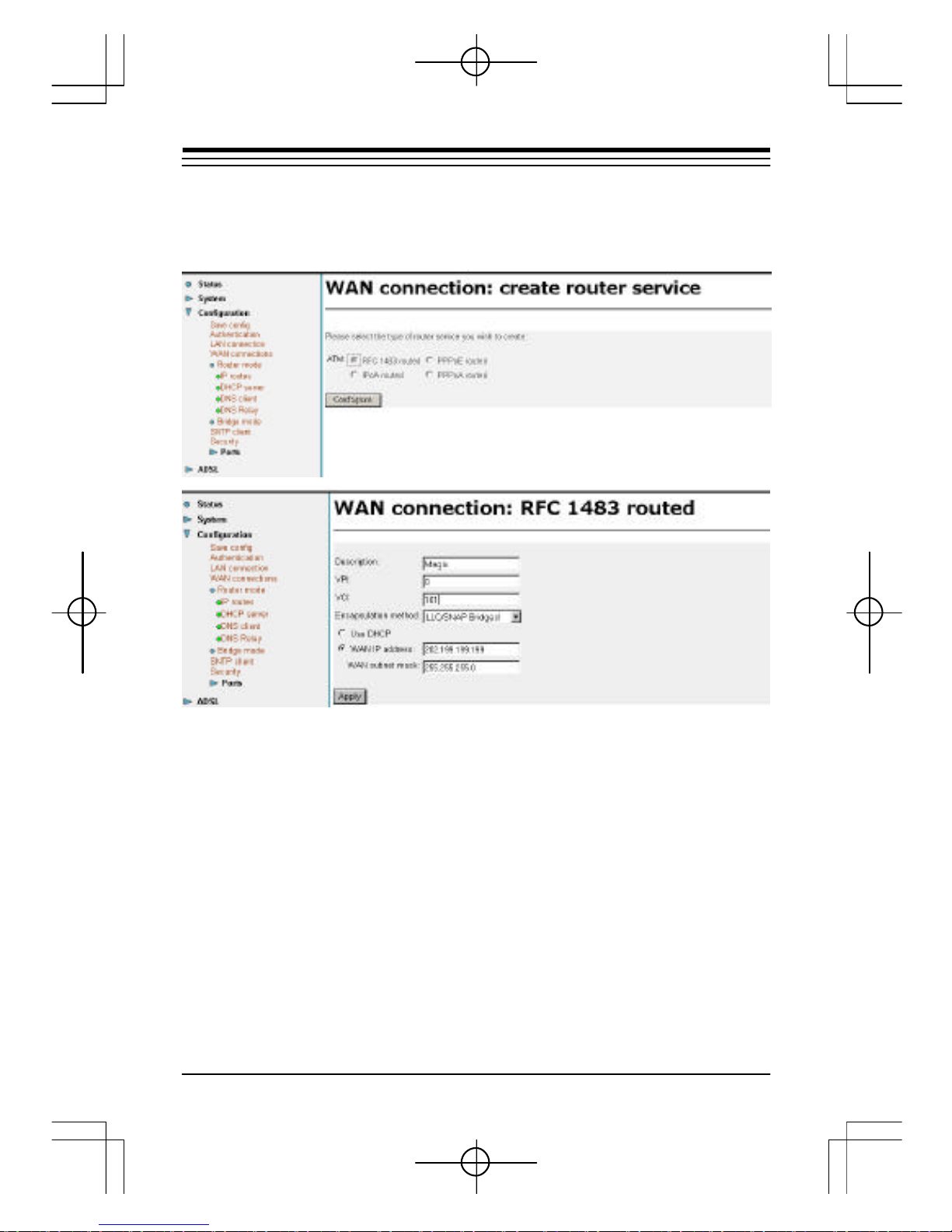
4.2.3 RFC 1483 Routed Configuration.
A. Click Router mode under Configura tion and choose RFC 1483 routed.
Click Configure and the interfa ce shows as below
• Description: Nam e of the WAN connection. (e.g. Magix)
• VPI/VCI: ATM VC of l ocal ISP (remote). (e.g. Magix ATM plan
VPI=0 , VCI=101)
• Encapsulation Method: Four methods: LLC/SNAP Routered,
LLC/SNAP Bridged, VcMux(null) Routered VcMux(null) Bridged.
Please s elect it according to ISP designation.
• Use DHCP: Use DHCP to allocate P C IP Address of WAN
from ISP. (default)
• WAN IP: Enter specified WAN IP address and WAN subnet
mask. (Provided by your ISP)
Section Four: Configure th e Bridge/Router
Page 25
24
Click Apply to continue
B. NAT Configuration.
Confi guration of NAT is the same as that of PPPoA Router mode, Please
refer to 4.2.1.B.(Page 17-20)
Section Four: Configure t he Bridge/Router
Page 26

25
C. Add default Gateway to IP routes.
If you uses static IP, have to add the default gateway (Pr ovided by your ISP)
to IP routes.
Click IP routes, key i n the gateway IP (provided by your ISP) to Gateway.
Interface: lea ve blank. Click OK button.
NOTE: Please remember to save the configuration after finishing
the settings.
Section Four: Configure th e Bridge/Router
Page 27

26
4.2.4 IPoA Routed Configuration.
A. Click Router mode under Configuration and choose IPoA routed.
B. NAT Configuration.
Configuration of NAT is the same as that of PPPoA Router m ode, Please
refer to 4.2.1.B.(Page 17 -20)
C. Add default Gateway to IP routes.
Confi guration of IP Routes is the same as the RFC 1483 Routed. Please
refer to 4 .2.3.C (Page 25)
Section Four: Configure t he Bridge/Router
Page 28

27
4.3 How to Configure DHCP Server.
Select DHCP Server, then click Configure to configure the DHCP Server
settings.
Section Four: Configure th e Bridge/Router
Page 29

28
4.4 How to set Port Forwarding.
Click Advanced NAT Configuration under Security .
Section Four: Configure t he Bridge/Router
Page 30

29
4.5 How to let Netm eeting pass through.
You may enable Firewall to let your netmee ting pass through. Select
Enable under Firewall, click Change State and select low under Security
Level, click Change Level.
Section Four: Configure th e Bridge/Router
Page 31

30
4.6 How to Configure Bridge M ode.
If you connect the Hurricane 8800P to the WAN port of another router as
bridge (Ethernet Modem), you need to set it to Bridge mode.
Click Bridge Mode, then Sl ect RFC 1483 Bridge or PPPoE Relay Bridge.
NOTE : If you connect it to your computer or HUB/Switch as Bridge
Mode, you need one REmote PPPoE client software to login to your
ISP for surfing the internet. e.g. WinPoET.
Section Four: Configure t he Bridge/Router
Page 32
31
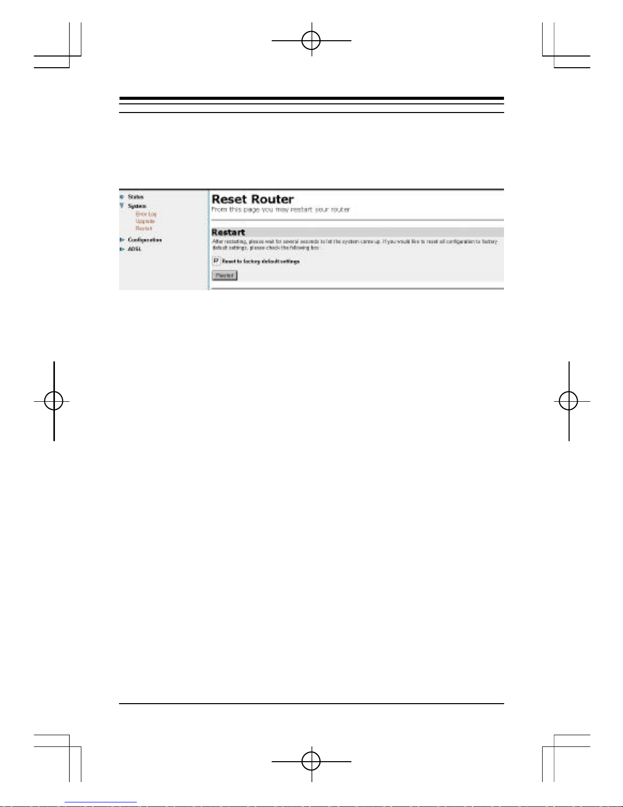
4.7 How to Restore to the Factory Default.
Click Restart under System, select reset to factory default Settings, then
click restart button.
Section Four: Configure th e Bridge/Router
Page 33

32
Appendix A - Troubleshooting
1. I can not get any connection. Power LED and LAN LED light up,
but the ADSL Link LED has no light .
1) Ensure that the ADSL line is activated.
2) Check that the Telephone cable (RJ-11) is connected to LINE Jack
on your router.
3) Unplug the RJ45 Cable (Network Cable), LAN LED will turn off,if
not, please pr ess reset button on your router.
If the problem still persists, please check with your ADSL Service Provider
to confirm the line condi tion.
2. I get ‘Request timed out’ response when I ping to the router.
1) Check that you have enter ed the correct IP Address for your
Ether net Card . (MS-DOS mode, type ipconfig to check your
computer’s IP, it should be in the same subnet as the router.)
2) Check the LAN LED whether it lights up. If not, check the cable
connecti on.
3) Press reset button to restart the Router again.
4) Restart your PC for the IP Addres s to take effect and try to ping
again.
3. I am not able to get the web configuration screen for the Router.
What can I do?
1) You may have to dis able the proxy settings on your Internet
browser.
2) Make sure that your browser is set to connect dir ectly .
Appendix A - Troubleshoot ing
Page 34

33
A. For Internet Explorer, click Tools, Internet Options, and
then the Connection tab. Make sure that Internet Explorer is
set to Never dial a connection.
B. For Netscape Navigator, click Edit, Preferences, Advanced,
and Proxy. Make sure that Netscape Navigator is set to Direct
connection to the Internet.
Appendix A - Troubleshooting
Page 35

34
Appendix B - High Protocols
1. IP
The modem will support next type IP packets:
RFC 1483 Routed (now in use)
The RFC in use is the 2684, but its PDU for IPV4 (802 networks) is similar
to the 1483. So both, the 1483 and 2684 are admitted fo r LLC encapsulation
for Routed protocols.
PPPoA as the RFC 2 364 (for near future use)
The modem wi ll support an PPP automatic session at the power on. Also,
sessio n will start if there is traffic detected on the user interface. A timer will
cancel the session after a cer tain inactivity time. Authentification will be
suppor ted by PAP & CHAP protocols.
PPPoEthernet (for near future use)
As RFC 2516 and RFC 1483 bridging. Authentification will be supported by
PAP & CHAP protocols.
2. Safety (access control)
The access for the different configur ation parameters will be protected by
password. A general res et will recover the standard password.
A firewall SW (in the interface and/or in the user equi pment) is very well
considered to avoi d external attack.
The modems who will be managed by Telefonica wi ll include the possibility of
establi sh a limited address range belonging to its management center.
3. Virtual Private Network support
It will be well considered the tunneling and encryption methods to create
Appendix B - High Protocols
Page 36

35
VPN's. The m echanisms should be based on standards, to warranty the
manufacturer independence of the other end s ervers for tunneling and
encryption.
Router
At least, the modem should support routing for IP protocol between user
LAN and WAN (through ADS L interface). This makes compulsory the
possi bility of configuring static routes. It is recommend the availability of
ARP proxy.
DHCP server
This service will assign the IP address, subnet mask, IP gateway plus the
primary & secondary DNS addr ess to all user's equipment.
NAT
NAT (Network Addres s Translation) is the translation of an Internet
Protocol address (IP address) used within one network to a different IP
address known within another network. One network is designated the
inside network and the other is the outside.
Bridge
It provides a tr ansparent and a spanning-tree bridge.
RFC 1483 bridged
The RFC in use i s the 2684, , the 1483 and 2684 are admitted for LLC
encaps ulation and VC multiplexing for bridged traffic.
PPPoE relay
It is used to transport P PP traffic over Ethernet.
PPPoEthernet client (RFC 2516)
Authentifi cation is supported by PAP & CHAP protocols. The RFC 2516
supports for multiple PVCs,with each VC suppo rting a single PPPoE session
(different ISPs over differ ent PVCs)
Appendix B - High Protocols
Page 37

36
BOOTP/TFTP client
Systems can be booted over Ethernet using BOOTP/TFTP. Once there is
a running image on the ASSP, the images and/or configuration stored in flash
can be updated using TFTP.
TELNET server
The modem provides a sim ple telnet server that allows administrative
acces s to the platform over TCP/IP. The implementation supports only a
single session at a time.
DMZ
(DeMilitar ized Zone) allows one IP address (or computer) to be exposed
to the Internet. Some applications requi re multiple TCP/IP ports to be
open. It is recommended that you set your computer with a static IP address
if you want to use DMZ Hos ting.
Appendix B - High Protocols
Page 38

37
Appendix C - Acronyms
ADSL Asymmetric Digital Subscriber Line
ANSI American National S tandards Institute
ATM Asynchr onous Transfer Mode
CHAP CHall enge Handshake Protocol
DHCP Dynami c Host Configuration Protocol
DNS Domai n Name Service
FTP File Transfer Pr otocol
HTML Hyper Text Mark Language
HTTP HyperText Transfer P rotocol
ICMP Internet Control Message Pr otocol
IP Inter net Protocol
IPoA IP over ATM
ITU International Telecommunication Union
LAN Local Area Network
MPoA Multipr otocol Encapsulation over ATM Adaptation Layer 5
(AAL5)
NAPT Network Address & Port Tr anslation
NAT Network Address Translation
PAP Password Authentication Pr otocol
PPP Point to Point Pr otocol
PPPoA PPP over ATM
PPPoE PPP over Ethernet
PVC Permanent VC
VC Virtual Connection
VP Virtual Path
WAN Wide Area Network
Appendix C - Acronyms
Page 39

38
Appendix D - EMC and Safety
EMC - CE Mark
Directive 89/336/EEC
EN 55022:1998 Class B/CISPR22:1997
EN 61000-3-2: 1995
EN 61000-3-3: 1995
EN 55024: 1998
Safety - CE Mark
Directive 72/23/EEC
IEC950/EN 60950
Appendix D - EMC and Safety
Page 40

39
Appendix E- Telecom Notices
CTR-2 1 Compliance Information
The equipment has been approved in accordance with Council ecis ion 98/
482/EC for pan- European single terminal connection to the public switched
tel ephone network (PSTN). However, due to differences between the
individual PS TNs provided in different countries, the approval dose not, of
its elf, give an unconditional assurance of successful operation on every
PSTN network termination point.
In the event of problems, you should contact your equipment supplier in the
first i nstace.
Note: the manufacturer should ensure that the vendor and user
of the equipment is clearly informed of the above information by
means of packaging and /or user manuals or other forms of user
instructions.
FCC Com pliance Information
The information in this document is subject to change without noti ce and
does not represent a commitment on the part of the vendor.
No warranty of representation, either expressed or implied, is made with
respect to the quality, accuracy or fitness for any particular purpose of this
document. The manufacturer reserves the r ight to make changes to the
content of this document and/or the products associated with it at any time
without obligation to notify any person or organi sation of such changes.
In no event wi ll the manufacturer be liable for direct, indirect, special,
incidental or consequential damages arising out of the use or inability to use
this product or documentation, even if advised of the possibility of such
damages.
Appendix E - Telecom Notices
Page 41

40
Micros oft Windows is a trademark of Microsoft Corporation.
Al l product names are trademarks or registered trademarks of their
respective owners.
FCC Compliance Statement
This device compli es with Part 15 and 68 of the FCC Rules. Operation is
subject to the following two conditions:
1.this device may not cause harmful interference, and
2.this device must accept any interference received, including interference
that m ay cause undesired operation.
FCC Warning Statement
This equi pment has been tested and found to comply with the limits for a
Class B digital device, pursuant to P art 15 and 68 of the FCC Rules. These
li mits are designed to provide reasonable protection against harmful
interference in a residential installation. This equipment generates, uses and
can emit radi o frequency energy and, if not installed or used in accordance
with the ins tructions, may cause interference to radio communications.
However, tel evision reception interference can be determined by turning
the equipment off and o n, the user is encouraged to correct the interference
by one or more of the foll owing measures:
• Reorient or relocate the receiving antenna
• Increase the separation between the equipment and the receiver
• Connect the equipment into an outlet different from that to which the
receiver is connected
• Consul t the dealer or an experienced radio/TV technician for help
Note: Changes or modifications not expressly approved by the
party responsible for compliance could void the user’s authority
to operate the equipm ent.
Appendix E - Telecom Notices
Page 42

PROLiNK TECHNICAL SUPPORT
At PROLiNK, we are committed to give you the best products as well as the best
technical support for installation of ADSL Bridge/Router.If there is virus in your
system, we may provide suggestions like where you can find the solution to clean
the virus, but we are unable to assist you until the virus is cleaned.
Service Centre
Tel : (65)62965455
Fax : (65)63925455
URL : www.fida.com
Email: support@fida.com
Address: Blk 105 Boon Keng Rd #06-13, Singapore 339776
Operating Hours: Mon-Fri :0900-1745 hrs Sat : 0900-1300 hrs
© Copyright 2000 Fida International (S) Pte Ltd. All Rights Reserved
 Loading...