

Pro-Line Boats 35 Express 2006 Owner's Manual
2006
Owner’s Manual
35 Express
Specifications subject to change without notice. Actual boats may vary from drawings and/or photos.
Copyright 2005 Pro-Line Boats Inc., PO Box 1348, Crystal River, FL 34423
All rights reserved. November 21, 2005

ii

Table of Contents
Introduction
Specifications . . . . . . . . . . . . . . . . . . . . . . . . . . . . . . . . . . . . . . . . . . . . . . . . . . . . . . . . 1
Dealer Responsibilities . . . . . . . . . . . . . . . . . . . . . . . . . . . . . . . . . . . . . . . . . . . . . . . . . 1
Customer Responsibilities . . . . . . . . . . . . . . . . . . . . . . . . . . . . . . . . . . . . . . . . . . . . . . 2
Owner’s Package . . . . . . . . . . . . . . . . . . . . . . . . . . . . . . . . . . . . . . . . . . . . . . . . . . . . . 2
Insurance and Registration . . . . . . . . . . . . . . . . . . . . . . . . . . . . . . . . . . . . . . . . . . . . . 2
Yacht Certification . . . . . . . . . . . . . . . . . . . . . . . . . . . . . . . . . . . . . . . . . . . . . . . . . . . . 3
Warranty . . . . . . . . . . . . . . . . . . . . . . . . . . . . . . . . . . . . . . . . . . . . . . . . . . . . . . . . . . . .3
Safety
Carbon Monoxide . . . . . . . . . . . . . . . . . . . . . . . . . . . . . . . . . . . . . . . . . . . . . . . . . . . . . 6
Emergency Treatment for CO Poisoning . . . . . . . . . . . . . . . . . . . . . . . . . . . . . 6
Where CO May Accumulate . . . . . . . . . . . . . . . . . . . . . . . . . . . . . . . . . . . . . . . 7
How To Protect Others and Yourself . . . . . . . . . . . . . . . . . . . . . . . . . . . . . . . . 7
Fire . . . . . . . . . . . . . . . . . . . . . . . . . . . . . . . . . . . . . . . . . . . . . . . . . . . . . . . . . . . . . . . . 8
Equipment . . . . . . . . . . . . . . . . . . . . . . . . . . . . . . . . . . . . . . . . . . . . . . . . . . . . . . . . . . 8
Flooding . . . . . . . . . . . . . . . . . . . . . . . . . . . . . . . . . . . . . . . . . . . . . . . . . . . . . . . . . . . . 9
Hazardous Conditions . . . . . . . . . . . . . . . . . . . . . . . . . . . . . . . . . . . . . . . . . . . . . . . . . 9
Passenger Safety . . . . . . . . . . . . . . . . . . . . . . . . . . . . . . . . . . . . . . . . . . . . . . . . . . . . . 9
Regulations . . . . . . . . . . . . . . . . . . . . . . . . . . . . . . . . . . . . . . . . . . . . . . . . . . . . . . . . . 10
Rules of the Road . . . . . . . . . . . . . . . . . . . . . . . . . . . . . . . . . . . . . . . . . . . . . . . . . . . . 10
Alcohol . . . . . . . . . . . . . . . . . . . . . . . . . . . . . . . . . . . . . . . . . . . . . . . . . . . . . . . . . . . . . 10
Controls
Throttle & Shift Controls for Twin or Triple . . . . . . . . . . . . . . . . . . . . . . . . . . . . . . . . . . 11
Ignition – Binnacle, Fwd, Neutral & Reverse Gear Operation . . . . . . . . . . . . . 11
Key Switch Alarm . . . . . . . . . . . . . . . . . . . . . . . . . . . . . . . . . . . . . . . . . . . . . . . 11
Lanyard Stop Switch . . . . . . . . . . . . . . . . . . . . . . . . . . . . . . . . . . . . . . . . . . . . 11
Electronic Throttle & Shift Controls (Optional) . . . . . . . . . . . . . . . . . . . . . . . . . . . . . . . 12
Shift / Throttle / Trim . . . . . . . . . . . . . . . . . . . . . . . . . . . . . . . . . . . . . . . . . . . . . . . . . . . 12
Steering - Hydraulic w/Tilt Steering . . . . . . . . . . . . . . . . . . . . . . . . . . . . . . . . . . . . . . . 12
Steering . . . . . . . . . . . . . . . . . . . . . . . . . . . . . . . . . . . . . . . . . . . . . . . . . . . . . . 13
Steering Wheel . . . . . . . . . . . . . . . . . . . . . . . . . . . . . . . . . . . . . . . . . . . . . . . . . 13
Power Trim . . . . . . . . . . . . . . . . . . . . . . . . . . . . . . . . . . . . . . . . . . . . . . . . . . . . 13
Trim Tabs . . . . . . . . . . . . . . . . . . . . . . . . . . . . . . . . . . . . . . . . . . . . . . . . . . . . . . . . . . .13
Windlass . . . . . . . . . . . . . . . . . . . . . . . . . . . . . . . . . . . . . . . . . . . . . . . . . . . . . . . . . . . .14
Systems and Accessories
Electrical System . . . . . . . . . . . . . . . . . . . . . . . . . . . . . . . . . . . . . . . . . . . . . . . . . . . . . 16
110 Volt Outlets - GFI Protected . . . . . . . . . . . . . . . . . . . . . . . . . . . . . . . . . . . 16
12 Volt Receptacle . . . . . . . . . . . . . . . . . . . . . . . . . . . . . . . . . . . . . . . . . . . . . . 16
Alternating Current and Direct Current Panels (AC/DC Panel) . . . . . . . . . . . . 16
Page
iii

Alternating Current (AC) . . . . . . . . . . . . . . . . . . . . . . . . . . . . . . . . . . . . . . . . . . 16
Direct Current (DC) . . . . . . . . . . . . . . . . . . . . . . . . . . . . . . . . . . . . . . . . . . . . . 17
Battery Charger . . . . . . . . . . . . . . . . . . . . . . . . . . . . . . . . . . . . . . . . . . . . . . . . 17
Battery Management System . . . . . . . . . . . . . . . . . . . . . . . . . . . . . . . . . . . . . . 17
Circuit Breakers . . . . . . . . . . . . . . . . . . . . . . . . . . . . . . . . . . . . . . . . . . . . . . . . 18
Blower . . . . . . . . . . . . . . . . . . . . . . . . . . . . . . . . . . . . . . . . . . . . . . . . . . . . . . . 19
Gas Generator w/Carbon Monoxide Detector (Optional) . . . . . . . . . . . . . . . . . 19
Shore Power with Cord . . . . . . . . . . . . . . . . . . . . . . . . . . . . . . . . . . . . . . . . . . 21
Switch and Breaker Panel . . . . . . . . . . . . . . . . . . . . . . . . . . . . . . . . . . . . . . . . 22
Lighting Systems . . . . . . . . . . . . . . . . . . . . . . . . . . . . . . . . . . . . . . . . . . . . . . . . . . . . . 25
Baitwell Light . . . . . . . . . . . . . . . . . . . . . . . . . . . . . . . . . . . . . . . . . . . . . . . . . . 25
Bilge Lights . . . .. . . . . . . . . . . . . . . . . . . . . . . . . . . . . . . . . . . . . . . . . . . . . . . . 25
Cabin Lights . . . . . . . . . . . . . . . . . . . . . . . . . . . . . . . . . . . . . . . . . . . . . . . . . . . 25
Cockpit Lights . . . . . . . . . . . . . . . . . . . . . . . . . . . . . . . . . . . . . . . . . . . . . . . . . . 26
Navigation and Anchor Lights . . . . . . . . . . . . . . . . . . . . . . . . . . . . . . . . . . . . . 26
Docking Lights (Optional) . . . . . . . . . . . . . . . . . . . . . . . . . . . . . . . . . . . . . . . . . 27
Remote Spot Light (Optional) . . . . . . . . . . . . . . . . . . . . . . . . . . . . . . . . . . . . . . 27
Spreader Lights (Optional) . . . . . . . . . . . . . . . . . . . . . . . . . . . . . . . . . . . . . . . . 27
Instrumentation . . . . . . . . . . . . . . . . . . . . . . . . . . . . . . . . . . . . . . . . . . . . . . . . . . . . . . 27
Compass . . . . . . . . . . . . . . . . . . . . . . . . . . . . . . . . . . . . . . . . . . . . . . . . . . . . . 27
Horn . . . . . . . . . . . . . . . . . . . . . . . . . . . . . . . . . . . . . . . . . . . . . . . . . . . . . . . . . 28
Full Instrumentation / Gauges . . . . . . . . . . . . . . . . . . . . . . . . . . . . . . . . . . . . . 28
Air Conditioning System (Optional) . . . . . . . . . . . . . . . . . . . . . . . . . . . . . . . . . . . . . . . 29
Fresh Water / Cabin Water System . . . . . . . . . . . . . . . . . . . . . . . . . . . . . . . . . . . . . . . 32
Fresh Water Tank . . . . . . . . . . . . . . . . . . . . . . . . . . . . . . . . . . . . . . . . . . . . . . . 32
Fresh Water Tank Fill . . . . . . . . . . . . . . . . . . . . . . . . . . . . . . . . . . . . . . . . . . . . 33
City Water Hook-Up/Inlet . . . . . . . . . . . . . . . . . . . . . . . . . . . . . . . . . . . . . . . . . 33
Fresh Water Stations . . . . . . . . . . . . . . . . . . . . . . . . . . . . . . . . . . . . . . . . . . . . 33
Fresh Water Faucet in Main Cabin . . . . . . . . . . . . . . . . . . . . . . . . . . . . . . . . . . 33
Fresh Water w/Pull Out Shower in Head . . . . . . . . . . . . . . . . . . . . . . . . . . . . . 33
Fresh Water w/Pull Out Shower at Transom . . . . . . . . . . . . . . . . . . . . . . . . . . 33
Fresh Water w/Pull Out Faucet at Bait Station . . . . . . . . . . . . . . . . . . . . . . . . . 33
Fresh Water Pump . . . . . . . . . . . . . . . . . . . . . . . . . . . . . . . . . . . . . . . . . . . . . . 33
Shower System & Shower Sump Pump . . . . . . . . . . . . . . . . . . . . . . . . . . . . . . 34
Water Heater . . . . . . . . . . . . . . . . . . . . . . . . . . . . . . . . . . . . . . . . . . . . . . . . . . 34
Head Waste System . . . . . . . . . . . . . . . . . . . . . . . . . . . . . . . . . . . . . . . . . . . . . . . . . . 34
What is the Law? . . . . . . . . . . . . . . . . . . . . . . . . . . . . . . . . . . . . . . . . . . . . . . . 34
Dockside Discharge Waste Outlet . . . . . . . . . . . . . . . . . . . . . . . . . . . . . . . . . . 35
Vacuum Flush with Overboard/Dockside Discharge . . . . . . . . . . . . . . . . . . . . 35
Head Macerator Pump . . . . . . . . . . . . . . . . . . . . . . . . . . . . . . . . . . . . . . . . . . . 36
Sea Water System . . . . . . . . . . . . . . . . . . . . . . . . . . . . . . . . . . . . . . . . . . . . . . . . . . . . 36
Baitwell Pump . . . . . . . . . . . . . . . . . . . . . . . . . . . . . . . . . . . . . . . . . . . . . . . . . . 36
Bilge Pumps . . . . . . . . . . . . . . . . . . . . . . . . . . . . . . . . . . . . . . . . . . . . . . . . . . . 37
High Water Alarm . . . . . . . . . . . . . . . . . . . . . . . . . . . . . . . . . . . . . . . . . . . . . . . 38
Fish Boxes with Macerator Pump . . . . . . . . . . . . . . . . . . . . . . . . . . . . . . . . . . . 38
Washdown Pump and Raw Water Washdown Hose . . . . . . . . . . . . . . . . . . . . 39
Fuel/Oil Systems . . . . . . . . . . . . . . . . . . . . . . . . . . . . . . . . . . . . . . . . . . . . . . . . . . . . . 39
Fuel Tank . . . . . . . . . . . . . . . . . . . . . . . . . . . . . . . . . . . . . . . . . . . . . . . . . . . . . 39
Fuel Fill and Vent . . . . . . . . . . . . . . . . . . . . . . . . . . . . . . . . . . . . . . . . . . . . . . . 41
Page
iv

Fuel Sender & Fuel Pick Ups . . . . . . . . . . . . . . . . . . . . . . . . . . . . . . . . . . . . . . 41
Fuel Water Separators . . . . . . . . . . . . . . . . . . . . . . . . . . . . . . . . . . . . . . . . . . . 41
Primer Bulbs . . . . . . . . . . . . . . . . . . . . . . . . . . . . . . . . . . . . . . . . . . . . . . . . . . . 42
Oil Tank and Oil Fill . . . . . . . . . . . . . . . . . . . . . . . . . . . . . . . . . . . . . . . . . . . . . 42
Fuel / Oil Leaks . . . . . . . . . . . . . . . . . . . . . . . . . . . . . . . . . . . . . . . . . . . . . . . . 42
Cabin Appliances & Accessories . . . . . . . . . . . . . . . . . . . . . . . . . . . . . . . . . . . . . . . . . 42
Refrigerator . . . . . . . . . . . . . . . . . . . . . . . . . . . . . . . . . . . . . . . . . . . . . . . . . . . 43
Electric Stove . . . . . . . . . . . . . . . . . . . . . . . . . . . . . . . . . . . . . . . . . . . . . . . . . . 44
Microwave . . . . . . . . . . . . . . . . . . . . . . . . . . . . . . . . . . . . . . . . . . . . . . . . . . . . 44
AM/FM Stereo with CD Player, Speakers and Remote . . . . . . . . . . . . . . . . . . 44
Stereo – XM Upgrade (Optional) . . . . . . . . . . . . . . . . . . . . . . . . . . . . . . . . . . . 45
Upgraded Stereo Package . . . . . . . . . . . . . . . . . . . . . . . . . . . . . . . . . . . . . . . . 45
Flat Screen Television w/DVD Player and Cable Outlet . . . . . . . . . . . . . . . . . 45
Windows, Doors & Hatches . . . . . . . . . . . . . . . . . . . . . . . . . . . . . . . . . . . . . . . . . . . . . 45
Windows . . . . . . . . . . . . . . . . . . . . . . . . . . . . . . . . . . . . . . . . . . . . . . . . . . . . . . 45
Windshield with Vent . . . . . . . . . . . . . . . . . . . . . . . . . . . . . . . . . . . . . . . . . . . . 46
Windshield Wipers . . . . . . . . . . . . . . . . . . . . . . . . . . . . . . . . . . . . . . . . . . . . . . 47
Cabin / Companionway Door . . . . . . . . . . . . . . . . . . . . . . . . . . . . . . . . . . . . . . 47
Hatches and Latches . . . . . . . . . . . . . . . . . . . . . . . . . . . . . . . . . . . . . . . . . . . . 47
Transom Door . . . . . . . . . . . . . . . . . . . . . . . . . . . . . . . . . . . . . . . . . . . . . . . . . 50
Tackle Box . . . . . . . . . . . . . . . . . . . . . . . . . . . . . . . . . . . . . . . . . . . . . . . . . . . . 50
Hardware . . . . . . . . . . . . . . . . . . . . . . . . . . . . . . . . . . . . . . . . . . . . . . . . . . . . . . . . . . .50
Cleats . . . . . . . . . . . . . . . . . . . . . . . . . . . . . . . . . . . . . . . . . . . . . . . . . . . . . . . . 50
Bow Rail . . . . . . . . . . . . . . . . . . . . . . . . . . . . . . . . . . . . . . . . . . . . . . . . . . . . . . 50
Grab Rails . . . . . . . . . . . . . . . . . . . . . . . . . . . . . . . . . . . . . . . . . . . . . . . . . . . . 50
Bow Pulpit w/Anchor Roller and Rope Locker Storage . . . . . . . . . . . . . . . . . . 50
Dive Platform - Integrated w/Ladder . . . . . . . . . . . . . . . . . . . . . . . . . . . . . . . . . 51
Cockpit / Deck Drains . . . . . . . . . . . . . . . . . . . . . . . . . . . . . . . . . . . . . . . . . . . . 51
Drain Plug . . . . . . . . . . . . . . . . . . . . . . . . . . . . . . . . . . . . . . . . . . . . . . . . . . . . . 51
Thru Hull Fittings . . . . . . . . . . . . . . . . . . . . . . . . . . . . . . . . . . . . . . . . . . . . . . . 51
Gunwale Trim / Rubrail . . . . . . . . . . . . . . . . . . . . . . . . . . . . . . . . . . . . . . . . . . . 53
Outriggers (Optional) . . . . . . . . . . . . . . . . . . . . . . . . . . . . . . . . . . . . . . . . . . . . 53
Hard Top (Standard Installation) . . . . . . . . . . . . . . . . . . . . . . . . . . . . . . . . . . . . . . . . . 53
Tower (Optional) . . . . . . . . . . . . . . . . . . . . . . . . . . . . . . . . . . . . . . . . . . . . . . . . . . . . . 54
Upholstery . . . . . . . . . . . . . . . . . . . . . . . . . . . . . . . . . . . . . . . . . . . . . . . . . . . . . . . . . .54
Cabinetry . . . . . . . . . . . . . . . . . . . . . . . . . . . . . . . . . . . . . . . . . . . . . . . . . . . . . . . . . . .54
Wood Grain Cabinetry . . . . . . . . . . . . . . . . . . . . . . . . . . . . . . . . . . . . . . . . . . . 54
Cabin Table . . . . . . . . . . . . . . . . . . . . . . . . . . . . . . . . . . . . . . . . . . . . . . . . . . . 54
Cabin Interior – Wood Upgrade (Optional) . . . . . . . . . . . . . . . . . . . . . . . . . . . . 54
Countertops . . . . . . . . . . . . . . . . . . . . . . . . . . . . . . . . . . . . . . . . . . . . . . . . . . . 54
Cabin Floors (Standard & Optional) . . . . . . . . . . . . . . . . . . . . . . . . . . . . . . . . . 55
Electronics (Optional) . . . . . . . . . . . . . . . . . . . . . . . . . . . . . . . . . . . . . . . . . . . . . . . . . . 55
Galvanic Isolator . . . . . . . . . . . . . . . . . . . . . . . . . . . . . . . . . . . . . . . . . . . . . . . . . . . . . 55
Bonding System . . . . . . . . . . . . . . . . . . . . . . . . . . . . . . . . . . . . . . . . . . . . . . . . . . . . . . 56
Operation & Performance
Trim / Tilt . . . . . . . . . . . . . . . . . . . . . . . . . . . . . . . . . . . . . . . . . . . . . . . . . . . . . . . . . . . 57
Propellers . . . . . . . . . . . . . . . . . . . . . . . . . . . . . . . . . . . . . . . . . . . . . . . . . . . . . . . . . . .58
Page
v

Starting . . . . . . . . . . . . . . . . . . . . . . . . . . . . . . . . . . . . . . . . . . . . . . . . . . . . . . . . . . . . . 58
Before Starting the Engines . . . . . . . . . . . . . . . . . . . . . . . . . . . . . . . . . . . . . . . 58
Starting the Engines . . . . . . . . . . . . . . . . . . . . . . . . . . . . . . . . . . . . . . . . . . . . . 58
After Starting the Engines . . . . . . . . . . . . . . . . . . . . . . . . . . . . . . . . . . . . . . . . 58
Fueling . . . . . . . . . . . . . . . . . . . . . . . . . . . . . . . . . . . . . . . . . . . . . . . . . . . . . . . . . . . . . 59
Before Fueling . . . . . . . . . . . . . . . . . . . . . . . . . . . . . . . . . . . . . . . . . . . . . . . . . 59
While Fueling . . . . . . . . . . . . . . . . . . . . . . . . . . . . . . . . . . . . . . . . . . . . . . . . . . 59
After Fueling . . . . . . . . . . . . . . . . . . . . . . . . . . . . . . . . . . . . . . . . . . . . . . . . . . . 59
Loading . . . . . . . . . . . . . . . . . . . . . . . . . . . . . . . . . . . . . . . . . . . . . . . . . . . . . . . . . . . . 59
Service and Care
Fiberglass and Gelcoat . . . . . . . . . . . . . . . . . . . . . . . . . . . . . . . . . . . . . . . . . . . . . . . . 60
Epoxy Barrier Coat and Bottom Paint . . . . . . . . . . . . . . . . . . . . . . . . . . . . . . . 60
Graphics . . . . . . . . . . . . . . . . . . . . . . . . . . . . . . . . . . . . . . . . . . . . . . . . . . . . . . . . . . . .61
Gunwale Trim/Rubrail . . . . . . . . . . . . . . . . . . . . . . . . . . . . . . . . . . . . . . . . . . . . . . . . . 61
Washdown Pump . . . . . . . . . . . . . . . . . . . . . . . . . . . . . . . . . . . . . . . . . . . . . . . . . . . . . 61
Fuel Water Separators . . . . . . . . . . . . . . . . . . . . . . . . . . . . . . . . . . . . . . . . . . . . . . . . . 62
Compass . . . . . . . . . . . . . . . . . . . . . . . . . . . . . . . . . . . . . . . . . . . . . . . . . . . . . . . . . . . 62
Aluminum . . . . . . . . . . . . . . . . . . . . . . . . . . . . . . . . . . . . . . . . . . . . . . . . . . . . . . . . . . . 62
Stainless Steel . . . . . . . . . . . . . . . . . . . . . . . . . . . . . . . . . . . . . . . . . . . . . . . . . . . . . . . 63
Corrosion Protection . . . . . . . . . . . . . . . . . . . . . . . . . . . . . . . . . . . . . . . . . . . . . . . . . . 63
Cabin/Companionway and Transom Doors . . . . . . . . . . . . . . . . . . . . . . . . . . . . . . . . . 63
Tackle Box . . . . . . . . . . . . . . . . . . . . . . . . . . . . . . . . . . . . . . . . . . . . . . . . . . . . . . . . . . 64
Windows . . . . . . . . . . . . . . . . . . . . . . . . . . . . . . . . . . . . . . . . . . . . . . . . . . . . . . . . . . . .64
Windshield . . . . . . . . . . . . . . . . . . . . . . . . . . . . . . . . . . . . . . . . . . . . . . . . . . . . . . . . . .64
Curtain Package and Windscreen . . . . . . . . . . . . . . . . . . . . . . . . . . . . . . . . . . . . . . . . 65
Canvas . . . . . . . . . . . . . . . . . . . . . . . . . . . . . . . . . . . . . . . . . . . . . . . . . . . . . . . 65
Insinglass . . . . . . . . . . . . . . . . . . . . . . . . . . . . . . . . . . . . . . . . . . . . . . . . . . . . . 66
Vinyl . . . . . . . . . . . . . . . . . . . . . . . . . . . . . . . . . . . . . . . . . . . . . . . . . . . . . . . . . . . . . . 66
Interior . . . . . . . . . . . . . . . . . . . . . . . . . . . . . . . . . . . . . . . . . . . . . . . . . . . . . . . 66
Exterior . . . . . . . . . . . . . . . . . . . . . . . . . . . . . . . . . . . . . . . . . . . . . . . . . . . . . . . 67
Cloth . . . . . . . . . . . . . . . . . . . . . . . . . . . . . . . . . . . . . . . . . . . . . . . . . . . . . . . . . . . . . . . 67
Cabin Cushions, Pillows and Curtains . . . . . . . . . . . . . . . . . . . . . . . . . . . . . . . 67
Shower Curtain . . . . . . . . . . . . . . . . . . . . . . . . . . . . . . . . . . . . . . . . . . . . . . . . . 67
Countertops . . . . . . . . . . . . . . . . . . . . . . . . . . . . . . . . . . . . . . . . . . . . . . . . . . . . . . . . . 67
Formica . . . . . . . . . . . . . . . . . . . . . . . . . . . . . . . . . . . . . . . . . . . . . . . . . . . . . . . . . . . . 68
Cabin Interior – Wood Upgrade . . . . . . . . . . . . . . . . . . . . . . . . . . . . . . . . . . . . . . . . . . 68
Appliances . . . . . . . . . . . . . . . . . . . . . . . . . . . . . . . . . . . . . . . . . . . . . . . . . . . . . . . . . .68
Refrigerator . . . . . . . . . . . . . . . . . . . . . . . . . . . . . . . . . . . . . . . . . . . . . . . . . . . 68
Microwave . . . . . . . . . . . . . . . . . . . . . . . . . . . . . . . . . . . . . . . . . . . . . . . . . . . . 68
Stove . . . . . . . . . . . . . . . . . . . . . . . . . . . . . . . . . . . . . . . . . . . . . . . . . . . . . . . . 69
Flooring . . . . . . . . . . . . . . . . . . . . . . . . . . . . . . . . . . . . . . . . . . . . . . . . . . . . . . . . . . . . 69
Laminated Wood Grain Flooring . . . . . . . . . . . . . . . . . . . . . . . . . . . . . . . . . . . 69
Teak and Holly . . . . . . . . . . . . . . . . . . . . . . . . . . . . . . . . . . . . . . . . . . . . . . . . . 69
Carpet . . . . . . . . . . . . . . . . . . . . . . . . . . . . . . . . . . . . . . . . . . . . . . . . . . . . . . . . 69
Winterization and Storage . . . . . . . . . . . . . . . . . . . . . . . . . . . . . . . . . . . . . . . . . . . . . . 69
Resealing . . . . . . . . . . . . . . . . . . . . . . . . . . . . . . . . . . . . . . . . . . . . . . . . . . . . . . . . . . . 70
Additional Cleaning and Maintenance Products . . . . . . . . . . . . . . . . . . . . . . . . . . . . . 70
Page
vi

Page
Appendix
Helpful Check Lists . . . . . . . . . . . . . . . . . . . . . . . . . . . . . . . . . . . . . . . . . . . . . . . . . . . 72
Each Time You Go On A Boat Trip . . . . . . . . . . . . . . . . . . . . . . . . . . . . . . . . . 72
Once A Month . . . . . . . . . . . . . . . . . . . . . . . . . . . . . . . . . . . . . . . . . . . . . . . . . 72
Once A Year . . . . . . . . . . . . . . . . . . . . . . . . . . . . . . . . . . . . . . . . . . . . . . . . . . . 72
Boat Identification Information . . . . . . . . . . . . . . . . . . . . . . . . . . . . . . . . . . . . . . . . . . . 73
Trouble Shooting Chart . . . . . . . . . . . . . . . . . . . . . . . . . . . . . . . . . . . . . . . . . . . . . . . . 74
Wiring Diagrams . . . . . . . . . . . . . . . . . . . . . . . . . . . . . . . . . . . . . . . . . . . . . . . . . . . . . . 75
While we endeavor to be as accurate as possible, certain changes in standard equipment, options and
the like may have occurred which would not be included in the Owner’s Manual. All weights and fuel
capacities are estimates and could/will vary with each vessel and with each application. In all cases,
consult your local Pro-Line dealer for the most current information.
vii

Introduction
Congratulations on the purchase of your new Pro-Line Boats 35 Express sport fishing boat. Welcome
into the proud family of satisfied Pro-Line owners. Every expedition lets you enjoy the outstanding
features designed into every boat we construct. Your new Pro-Line is more than just a boat, it's a whole
new lifestyle.
Pro-Line's commitment to the needs and wishes of the sport fishing family has resulted in a superior
fishing craft providing you with comfort, performance, security, and outstanding fishability. All of our boats
comply with U.S. Coast Guard (USCG) safety regulations and are designed and crafted in accordance
with the National Marine Manufacturers Association (NMMA), the American Boat and Yacht Council
(ABYC) standards, and the Common European directive (CE).
This manual (to be kept onboard your Pro-Line) is designed to provide you with information necessary for
the safe, efficient operation and care of your new Pro-Line. Take the time now to carefully review the
owner’s manual and the additional information in your owner’s package to maximize your enjoyment and
safety as well as familiarize yourself with your new boat.
We have prepared this manual to help you fully enjoy each voyage while operating your boat safely.
While the information in the manual cannot and does not cover every boating situation, we urge you to
read this manual carefully and familiarize yourself with the boat before using it. If a specific method or
procedure is not recommended, you must make sure that whatever action you take is safe for you, your
passengers and others on the water. Always use common sense when boating.
Specifications
Length Overall (LOA) 35’ 6” Bridge Clearance
Beam 12’ 6” w/ Hard Top 10’ 2”
Draft (Hull) 25” w/ Tower 15’ 3”
Deadrise
Weight (Estimate) Fuel Capacity 320 gallons
Hull – w/o Engines 11,200 lbs. Baitwell Capacity 45 gallons
Trailerable 15,000 lbs. Fishbox Capacity (2) 125 gallons
Cockpit Area 115 sq. ft. Freshwater Capacity 60 gallons
Cockpit Depth 25” Water Heater Capacity 6 gallons
Headroom in Cabin 6’ 10” VacuFlush Holding Tank Capacity 10 gallons
Headroom in Head 6’ 0”
Dealer Responsibilities
Your dealer's responsibilities include but are not limited to:
• Pre-delivery verification of proper rigging and operation. Deliver the boat in water ready
condition unless you and your dealer have agreed upon other arrangements.
• Complete the pre-delivery checklist with the customer at the time of delivery.
• Provide adequate orientation in the general operation of your Pro-Line including an
explanation of the specific safety considerations regarding the use of the systems and
components.
• Provide an explanation of the owner’s package and literature, including the warranty
registration cards for the vessel, engines and all of the separately warranted equipment
Maximum Horsepower 900 hp
19

and accessories.
• Discuss the terms of all warranties and emphasize the importance of registering each
warranty with the specific manufacturers.
• Repair any damages that may have occurred to the boat while the boat has been in the
dealer’s possession.
• Provide service to Pro-Line boat owners within the locality of the dealership.
• Explain local and out of area service procedures during and after the warranty periods.
Customer Responsibilities
• Review and sign the Pre-Delivery Inspection (PDI) report for the boat and motors with
your dealer to ensure that your boat is in top condition when you take delivery.
• Examine the boat at time of delivery to insure that all systems and components are
functioning safely and properly. Report any outstanding issues (i.e., scratches, missing
items, etc.) to your dealer before or during the delivery of the boat.
• Read all literature and instructions to ensure proper usage and operation of the
equipment as well as how to use and maintain all equipment as directed.
• Read and understand the limited warranty. Sign the warranty registration card and mail
it to Pro-Line Boats.
• Contact your local Pro-Line dealer for assistance with any warrantable repairs.
• Transportation of your boat to and from your dealer or repair facility for warrantable
repairs.
• Schedule your 20-hour boat and engine check up with your dealer.
• Know your boat and the rules of the road before you use your boat.
• Be proficient in boat handling and safety. This manual is not intended to provide
complete training on all aspects of general boat operations. We at Pro-Line urge
all boat owners and operators to attend a boating safety course before operating a
boat.
Owner’s Package
Each Pro-Line boat comes with an Owner’s Package that contains this Owner’s Manual along with
materials supplied by various manufacturers whose products have been installed on your boat.
Manufacturers of certain products (i.e., Stereo, TV, Stove, Refrigerator, Microwave, Engines, Electronics,
etc.) provide their own limited warranty and owner’s manuals. While we have endeavored to be as
accurate as possible in this manual, if you should notice a discrepancy between the information in this
manual and that of the individual supplier’s manual, always follow the instructions in the supplier’s
manual.
Make sure that you complete the individual warranty cards for these products and forward them on to the
respective manufacturers to register for your warranty with them. Retain all materials in your Pro-Line
Owner’s Package for easy reference.
Insurance and Registration
As the owner of the boat, you are legally responsible for all liabilities of operation. Secure insurance
protection with a reputable insurance company through your local insurance agent.
Learn about and operate your boat in accordance with local, state, and federal laws, regulations, and
registration requirements.
2

Yacht Certification
In accordance with the National Marine Manufacturers
Association (NMMA) and the American Boat and Yacht
Council (ABYC), all boats larger than 26 feet in length are
required to be Yacht Certified. Therefore, a per person
and/or pound capacity is not assigned to vessels over 26
feet in length. It is up to the operator’s discretion to
determine a safe load. These yacht standards are based
on Standards and Recommended Practices for Small
Craft published by the ABYC, 3069 Solomons Island
Road, Edgewater, MD 21037 (410-956-1050).
Warranty
The Pro-Line Boats Limited Warranty is attached to the warranty card. After signing the warranty card,
your dealer will provide you with your copy of the warranty and mail the warranty card to Pro-Line Boats,
Inc. A copy of the Pro-Line Boats Limited Warranty is also included in this chapter.
The Pro-Line Boats Limited Warranty extends only to parts that were factory installed. Dealer installed
items are the responsibility of the dealer. All warrantable repairs are to be completed by an authorized
Pro-Line dealer. Your dealer should be able to assist you with any service or warranty related issues.
If for any reason you are dissatisfied with the services performed by your dealer, we suggest that you
discuss the matter with the service manager. The service manager is responsible for the quality of
service being performed and has a direct interest in resolving your issues to your satisfaction. If the
matter is complicated and cannot be resolved to your satisfaction by the service manager, we suggest
that you talk to the general manager or owner. In most cases a compromise can be reached.
If the matter cannot be resolved by the dealership to your satisfaction, contact the Pro-Line Boats
Customer Service Department by calling 352-795-4111 or by writing to:
Pro-Line Boats, Customer Service Dept.
PO Box 1348
Crystal River, FL 34423-1348
FAX: 352-795-9373
So that your dealer and we can provide you with the best possible service, please have the following
information available when calling or writing:
HIN (Hull Identification Number)
Selling dealer’s name and location
Servicing dealer (if different from selling dealer)
Nature of problem
3

Names of dealership personnel involved with the situation
Record of service performed and approximate dates
When contacting Pro-Line Boats, please keep in mind that your issue will most likely be resolved
at the dealership, using their facilities, equipment, personnel and/or sublet repair facilities.
Note: There are items that are not covered
limited to the following:
• Incidental and consequential damages (i.e., storage charges, telephone or rental charges
of any type, inconvenience or loss of time or income).
• Damage caused by neglect, lack of maintenance, accident, abnormal operation, improper
installation or service.
• Haul-out, launch and towing charges.
• Transportation charges, service call charges and/or travel time to and from a repair
facility, customer’s home or marina.
• Service requested by customer other than that which is necessary to satisfy the warranty
obligation.
• Oils, lubricants or fluids used in normal maintenance.
• Air freight, next-day or second-day air, or any special delivery fees unless pre-approved.
• Gelcoat cracking, chalking, crazing, discoloration, yellowing or blistering.
• Hull blisters that form below the water line: Osmosis blistering is not covered by our
limited warranty. The phenomenon of osmotic blistering is known to occur in salt water,
brackish water and/or fresh water. Any boat left in the water for any period of time is
susceptible. Most marine bottom paint manufacturers offer coatings that help protect the
hull against osmosis blistering. We highly recommend that you add a protective coating
to your hull. Find out which type of bottom paint is recommended for your area and have
an epoxy barrier coat and bottom paint applied by a professional.
• Parts not installed by the factory
The Ten Year Limited Hull Structural Warranty is transferable to subsequent owners for a nominal fee.
Please contact your dealer or Pro-Line Boats to obtain the applicable transfer form so that the new owner
will have piece of mind knowing that their pre-owned boat comes with the same structural hull warranty
protection that was afforded to the original owner.
by the Pro-Line Boats Limited Warranty, including but not
4
5

Safety
Your Pro-Line boat has been constructed with safety in mind. But, remember, boating safety and the
safety of your passengers is YOUR ultimate responsibility. You should fully understand the operations of
your vessel as well as the basics in boating safety.
Your local U.S. Coast Guard Auxiliary (USCGA) and the U.S. Power Squadrons (USPS) offer excellent
safe boating classes several times a year. If you have not already passed a boating safety course, we
recommend that you do so at your earliest convenience.
Plan your trips carefully. Insure ample fuel supply and a reserve. Tell someone where you are going and
when you expect to return. Keep current charts onboard. Read USCG boating safety circulars and follow
the safety guidelines.
Carbon Monoxide
Be aware of and avoid conditions that can cause Carbon Monoxide poisoning (see USCG boating safety
circular 77). Sources of Carbon Monoxide (CO) include any gas or diesel engine and any flame from
items such as a charcoal grill, stove or heater. Carbon Monoxide can accumulate to deadly levels in
enclosed spaces. Always ventilate occupied areas of the vessel with fresh clean air.
In high concentrations, CO can be fatal within minutes. The effects of CO in lower concentrations are
cumulative and can be just as lethal over long periods of time. CO poison is often confused with
seasickness. So be aware of the following CO symptoms: Itchy and watery eyes, flushed appearance,
throbbing temples, inability to think coherently, ringing in the ears, tightness across the chest, headaches,
drowsiness, nausea, dizziness, fatigue, vomiting, collapse and convulsions.
Do not stand or swim near the motor when the engine is idling.
Carbon monoxide can harm and even kill you inside or outside your boat!
Did you also know:
• CO symptoms are similar to seasickness or alcohol intoxication?
• CO can affect you whether you're underway, moored or anchored?
• You cannot see, smell or taste CO?
• CO can make you sick in seconds? In high enough concentrations, even a few breaths
can be fatal.
Most important of all, did you know CO poisonings are preventable? Every boater should be aware of
the risks associated with CO - what it is; where it may accumulate; and the symptoms of CO poisoning.
To protect yourself, your passengers and those around you, learn all you can about CO.
Emergency Treatment for CO Poisoning
CO poisoning or toxicity is a life-threatening emergency that requires immediate action. The following
is a list of things that should be done if CO poisoning is suspected. Proceed with caution. The victim
may be in an area of high CO concentration, which means you or others could also be in danger from
exposure to CO.
• Evaluate the situation and ventilate the area, if possible.
• Evacuate the area and move affected person(s) to a fresh air environment.
• Observe the victim(s).
• Administer oxygen, if available.
6

• Contact medical help. If the victim is not breathing, perform rescue breathing or
approved cardiopulmonary resuscitation (CPR), as appropriate, until medical help arrives.
Prompt action can mean the difference between life and death.
• Shut off potential sources of CO, if possible. Correct ventilation problems and/or repair
exhaust problems as appropriate. Investigate the source of CO and take corrective
action, such as evacuating and ventilating the area or shutting off the source of the CO,
while at the same time evacuating and ventilating the area.
Where CO May Accumulate - Carbon Monoxide can accumulate anywhere in or around your boat
as shown in the following pictures:
Inadequately ventilated canvas enclosures.
Exhaust gas trapped in enclosed places.
Blocked exhaust outlets.
Another vessel's exhaust. CO from the boat docked next to you can
be just as deadly.
"Station wagon effect" or back drafting.
At slow speeds, while idling, or stopped. Be aware that CO can
remain in or around your boat at dangerous levels, even if your
engine or the other boat's engine is no longer running!
How to Protect Others & Yourself
You are in command of your boating safety. Follow these simple steps to help keep Carbon Monoxide
from poisoning you, your passengers or others around you.
7

• Know where and how CO may accumulate in and around your boat.
• Maintain fresh air circulation throughout the boat at all times. Run exhaust blowers
whenever the generator is operating.
• Know where your engine and generator exhaust outlets are located and keep everyone
away from these areas.
• Never sit, teak surf or hang on the back deck or swim platform while the engines are
running. (Teak Surfing is a new and dangerous boating fad that involves an individual
holding on to the “teak” swim platform of a vessel while a wake builds up then lets go to
body surf on the wave created by the boat; hence the term - Teak Surfing.) Teak surfing
is never a safe activity.
• Never enter areas under swim platforms where exhaust outlets are located unless the
area has been properly ventilated.
• Although CO can be present without the smell of exhaust fumes, if you smell exhaust
fumes, CO is also present. Take immediate action to dissipate these fumes.
• Treat symptoms of seasickness as possible CO poisoning. Get the person into fresh air
immediately. Seek medical attention unless you are sure it is not CO.
• Install and maintain CO alarms inside your boat. Do not ignore any alarm. Replace
alarms as recommended by the alarm manufacturer.
• Get a Vessel Safety Check. A VSC is a free bow-to-stern safety examination.
Fire
• Be aware of and avoid conditions that can lead to accidental fire.
• Guard against and watch for fuel spills and leaks.
• Inspect wiring for damage or exposure that could lead to short circuits or arcing.
• Make sure those who smoke are careful to avoid accidental fire ignition.
• Do not allow smoking while fueling.
• Keep a USCG approved fire extinguisher on board at all times.
• Inspect the fire extinguisher regularly, learn how to use it properly and instruct others as
well.
• Use water to fight a fire as a last resort after making arrangements to abandon the boat if
a fire should get out of control.
• Keep the following in mind if a fire is burning out of control and you must abandon the
boat:
o Abandon the boat into the wind to minimize burn risk from floating fuel.
o Wear a PFD unless you must swim under burning fuel.
o If swimming under burning fuel, throw a PFD outside of the burning area
and swim under the burning fuel to it.
Equipment
USCG regulations require that you have the following Coast Guard approved equipment onboard while
operating your boat:
• Fire extinguisher(s)
• Personal Flotation Device (PFD) for each occupant
• One throwable PFD
• Sound signal device
• Navigational lights if operated at night
• Sight signal device approved for day and night use when in coastal waters or the great
lakes
8

In addition, here is a list of suggested equipment you should have aboard your Pro-Line:
• First aid kit and blankets • Anchor and sea anchor with sufficient line
• Mooring lines and fenders • Bailing device
• Combination oar/boat hook • Tool kit and lubricant
• Spare prop and hardware • Spare fasteners, hose clamps and plugs
• Spare fuses and bulbs • Binoculars
• Local charts and compass • Waterproof flashlight and spare batteries
• 2 way radio • EPIRB (emergency beacon)
• Floating key chain and spare keys • Navigation device
• Emergency food and water • Waterproof matches or lighter
Flooding
Be aware of and avoid conditions that can cause your boat to flood with water. Possible causes of
flooding include:
• Damage to the hull or thru-hull fitting
• Waves washing into the boat
• Water entering cockpit due to improper loading
• Failure to properly install the drain plug.
The boat will become flooded and may swamp, capsize or sink if water enters the boat faster than the
bilge pump can expel it.
Hazardous Conditions
Keep track of weather developments and avoid hazardous conditions whenever possible. When forced to
operate your Pro-Line in storm conditions:
• Wear PFD's.
• Stow loose gear and equipment.
• Place heavy items as low as possible.
• Head for the easiest port to reach a safe location.
• Reduce speed. You are moving too fast if the boat leaves the water.
• If power fails, anchor or rig a sea anchor off the bow (an empty ice chest in a pinch).
• Stay with the boat if it capsizes, unless it is burning out of control.
Passenger Safety
You are responsible for the safety and conduct of your passengers. Make sure that:
• You instruct your passengers on the proper use and location of PFD's. Children and
non-swimmers should wear one at all times.
• Each passenger is in a safe location when underway and knows to keep the boat
balanced.
• At least one other person knows how to operate the boat in case of an emergency.
• Your passengers are aware of propeller dangers and the possibility of sudden maneuvers
and jolts.
9

• The engine is turned off and the key is removed when swimmers are near the prop or
using the dive platform.
• All passengers keep away from lines under stress in case they break and recoil.
Regulations
The USCG is the authority of all waterways. Local authorities enforce State Boating Regulations. You
are subject to marine traffic laws and "Rules of the Road" for both federal and state waterways.
Therefore, you must submit to boarding if requested by the proper authority. There are many publications
available from the Coast Guard concerning regulations. Call the United States Coast Guard Info Line at
(800)-368-5647 for additional information.
Rules of the Road
Know and use the “Rules of the Road”. Your boat is subject to U.S. Coast Guard enforced marine traffic
laws know as “Rules of the Road.” There are two sets of rules: the US Inland Navigation Rules and the
International Rules. The latter rules are applicable to all vessels inside the demarcation lines separating
inland and international waters. You may obtain a copy of the rules from any of the following and by
requesting the publication titled “Navigational Rules, International - Inland.”
• Your local USGC
• The United States Coast Guard Info Line (800)-368-5647
• The USCG Headquarters by logging on to uscg.mil
The information here is only a “brief” overview. Please
• Audible warning signals:
o One short horn blast: starboard course change.
o Two short horn blasts: port course change.
o Three short horn blasts: astern operation.
o Five horn blasts: doubt about previous signal or danger.
o A Five-second horn blast every minute: for fog operation.
• When overtaking, give-way vessel announces intention with horn blast(s) and waits for a
response, then completes maneuver.
• When approaching head-on, both boats give way after giving appropriate horn blast(s)
(preferably to starboard).
• When crossing, a vessel converging from starboard has the right-of-way. Port vessel
gives way (both acknowledge with one short horn blast).
• Know and observe navigational buoys and markers.
• Give way to craft under sail.
contact the USCG for detailed information.
Alcohol
Don't drink and drive. If you have been drinking, appoint someone who is an experienced boater and has
not been drinking to be the designated driver. Never operate a boat under the influence of drugs or
alcohol. Operation of motorized vessels while under the influence is a Federal offense carrying a
significant penalty.
10
Controls
Controls and engine systems vary greatly from one engine manufacturer to another. Please read your
engine owner’s manual carefully.
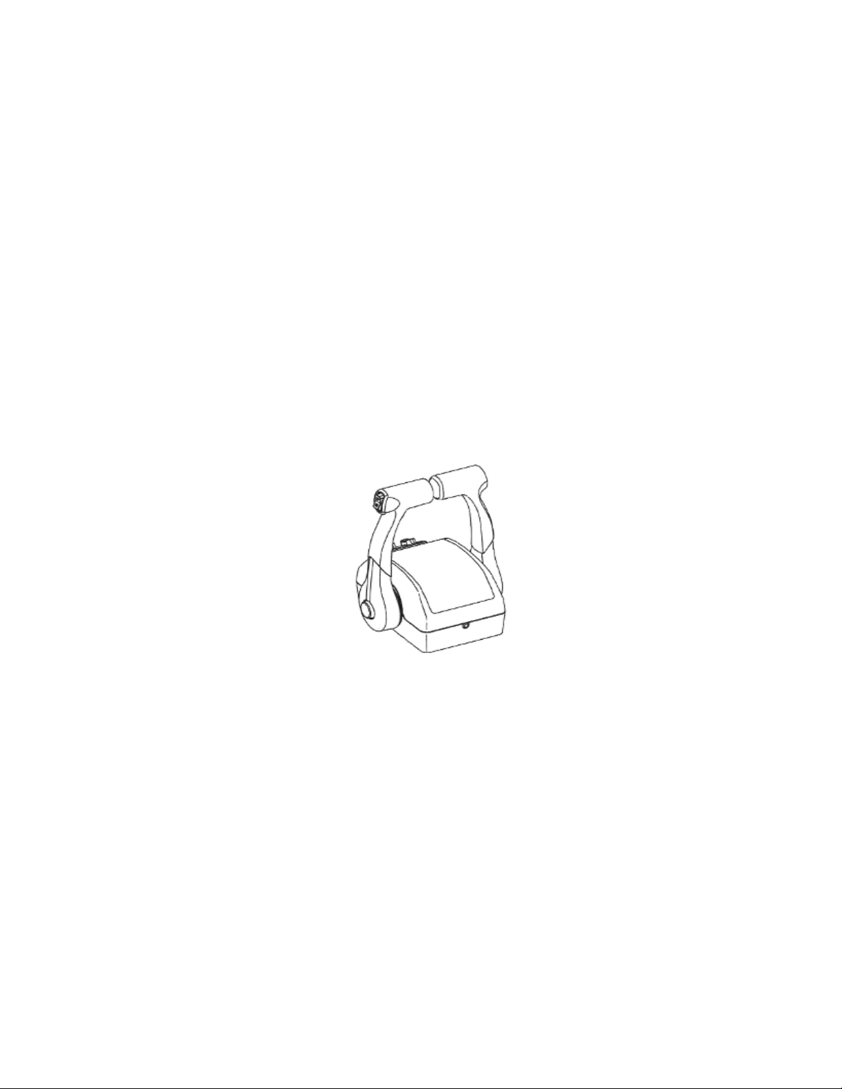
Throttle & Shift Controls for Twin or Triple
Ignition – Binnacle, Forward, Neutral and Reverse Gear Operation
The Binnacle on the 35 Express is located on the starboard side of the console forward of the helm seat.
To ensure that the Binnacle is working properly, shift the Binnacle forward to put the engine in forward
gear. Make sure the engine shifts smoothly into idle with no grinding of the gears. Bring the Binnacle
back into neutral and repeat the same process while going into reverse. Again, ensure that there are no
gears grinding. It is important to check the Binnacle at wide-open throttle (WOT) to ensure the Binnacle
is not stiff and operates smoothly while going into the WOT position.
Actual Binnacle will vary depending upon the engine package that was selected.
Key Switch Alarm
The Key Switch Alarm is located in the binnacle and sounds when the ignition key is turned on. The Key
Switch Alarm is actually is a warning alarm that goes off when any overheating problems may occur with
the engine. To check the Key Switch Alarm, turn the ignition key to the right but do not start the engine.
The alarm will sound ensuring that the engine warning alarm is working properly. When finished, turn the
key off.
Lanyard Stop Switch
To ensure the lanyard stop switch (also called the emergency stop feature) on the engine works properly,
first turn on the ignition key and start up the engine. While the engine is running, locate the lanyard stop
switch. The lanyard stop switch will be either on the base of the binnacle or underneath the ignition key.
While the engine is running in the neutral position, pull the lanyard stop switch downward until the plastic
element at the end of the lanyard pulls the stop switch pin into the off position. This process will
automatically stop the engine and will ensure that the emergency lanyard stop switch is working properly.
11

Electronic Throttle & Shift Controls (Optional)
Some engine packages (i.e., Mercury Verado, Mercury Opti Max DTS, etc.) include Electronic Throttle &
Shift Controls. This option is also available as an option for all other engine packages. The Electronic
Throttle & Shift Controls provide easier shift and throttle functions and little or no resistance. You may
occasionally feel some friction at the binnacle but this can be adjusted at the binnacle per the instructions
provided by the engine manufacturer.
If your engine package includes the optional Electronic Throttle & Shift Controls and you have purchased
the optional Tower for the Hard Top, the Tower controls will also be electronic.
Shift / Throttle / Trim
Your Pro-Line can be ordered with different shift/throttle systems based upon motor type. Refer to the
owner's packet to find the manual pertaining to your particular installation. Each motor has an individual
tilt/trim switch located on the port throttle lever. Separate shift and throttle controls are available for each
outboard motor.
The throttle lever has three range positions: “Forward”, “Neutral”, and “Reverse”. The shift function
occurs in the first portion of the lever travel. After the transmission is shifted into gear, further movement
of the lever advances the throttle.
Push the throttle lever ahead to move forward and pull it back for reverse. Centralize the lever to the
detent for neutral. The throttle lever is equipped with a neutral safety switch to prevent the motor from
starting in gear. The initial short movement of the lever to engage the transmission should be made firmly
to avoid causing gear clash.
CAUTION: Use care in shifting to avoid advancing the throttle more than intended.
Steering - Hydraulic with Tilt Steering
Steering systems will differ depending upon your selection of engine package. Please carefully read the
owner’s manual provided by the specific manufacturer.
12

Steering
Your Pro-Line is equipped with a self-contained hydraulic steering system. When the steering wheel is
turned, the helm pump pumps fluid to the steering cylinder causing it to extend or retract. Periodically,
check the fluid level and fill as necessary. Beware of adding too much fluid, especially if the ambient
temperature is cold because subsequent expansion could cause leaking or damage to your system.
Refer to the owner’s manual that was provided by your engine manufacturer.
After every 24 hours of operation check all nuts, caps, and hose fittings for tightness. Make sure the
hoses are not chafing or kinking on sharp corners. Also, check that hose ends are not damaged or
distorted. The fluid should be changed annually under normal conditions and every six months during
times of heavy usage. If your steering does not operate properly, check the following:
• Drive entanglements
• Level of the hydraulic steering fluid
• Hoses and/or fittings for leaks
• Air in the steering system.
To properly check the Steering system on the 35 Express, start by turning the steering wheel port to
starboard. If the engine does not respond the same time as the steering wheel is being turned, this
means that there is air in the Steering system and the Steering system needs re-bleeding. When there is
air in the steering, the steering wheel will feel “loose”. Contact your dealer to have them bleed the
steering system.
Steering Wheel
The stainless steel Steering Wheel is mounted at the helm
along with the binnacle, switch panel and other controls.
Please refer to the Care and Maintenance section of this
manual for cleaning recommendations.
Power Trim
The Power Trim unit is located on the engine and can be operated by using the trim button on the engine
or by using the trim toggle switch on the binnacle. To ensure the Power Trim is working, start by pressing
the toggle trim switch in the up position and trim the engine to the full up position. Repeat the same
process by pressing the trim toggle switch down and the engine will go into the full down position. See
the Trim and Tilt information in the Operations section of this manual.
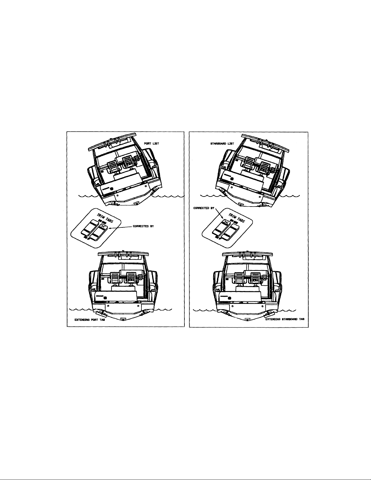
Trim Tabs
The Trim Tabs on the 35 Express come equipped with auto retract. The planing tabs are located on each
side of the transom on the bottom of the hull. The Trim Tabs operate independently, up or down, to
correct for differing conditions of wind or load. Refer to the owner’s packet for specific information.
Check the operations of your Trim Tabs before getting underway. To operate the Trim Tabs locate the
Trim Tab rocker switches on the console. Press both switches forward and hold them down. This will
engage both Trim Tabs and will ensure they are working properly while in the full down position.
The switch on the port side operates the starboard Trim Tab. The switch on the starboard side operates
the port Trim Tab. To check each Trim Tab individually, press one of the Trim Tab rocker switches to the
forward position and check to see if the opposite Trim Tab goes down. For example if the starboard Trim
13
Tab switch is being pressed down, the port Trim Tab should be going down. Repeat the same process
for the opposite side.
While underway and in open water, clear of other boaters, depress the top half of the switches in halfsecond increments to achieve the desired degree of trim. To correct a starboard list, depress the top half
of the port switch in small increments until the list is corrected. To avoid over trim, allow a few seconds
between tab adjustments to allow the boat to respond. If you over trim, simply give the over trimmed tab
an adjustment in the opposite direction. Push the top half of both rocker switches in half-second
increments to trim the bow down.
Warning: Trim tabs can cause a dramatic change in the attitude and heading of your
boat. Adjust them in small increments when in open water and clear of any obstructions.
Windlass w/Rope & Chain
The Windlass anchor system is located on the bow of the 35 Express. It is an electric hands free anchor
system that allows the driver to raise or lower the anchor while staying at the helm. The windlass comes
with 200 feet of ½ inch line and 6 feet of ¼ inch rode.
The windlass is operated by a separate switch and is protected by a 50-amp breaker. The switch is
located at the helm. The breaker is located on the console in close proximity to the switch.
14
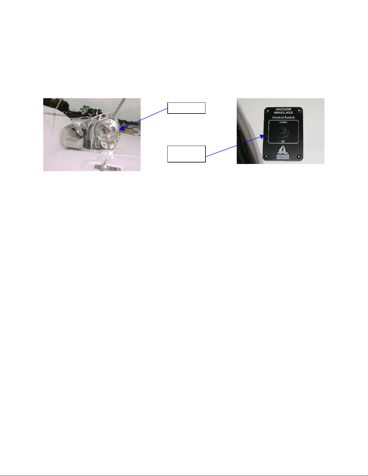
To operate the Windlass, press the Windlass toggle switch to the down position to release the anchor and
line. After dropping the anchor, be sure to tie the line off at one of the cleats. If you do not tie off at a
cleat, the constant pull against the line could cause the windlass motor to fail. To retrieve the anchor,
press the Windlass switch to the up position and carefully raise the anchor up but not allowing it to hit the
boat.
Windlass
Windlass
Switch
Refer to the owner’s manual that was provided by the manufacturer of the Windlass for operational
procedures and information related to the care and maintenance of their product. When in doubt, always
defer to the Windlass manufacturer’s instructions and/or recommendations.
15

Systems and Accessories
Electrical System
110 Volt Outlets - GFI Protected
There are 3 (three) 110 volt/ground fault interrupter (GFI) outlets installed in the cabin and power to these
outlets is provided via the Cabin Outlet 1 and the Cabin Outlet 2 switches on the AC/DC panel. The
Cabin Outlet 1 switch controls the outlets in the dinette area and the head area. A plastic cover that flips
up for easy access protects the outlet in the head area. The Cabin Outlet 2 switch controls the outlet in
the galley.
12 Volt Receptacle
The boat is equipped with 2 (two) 12 volt receptacles that are installed on the console. They are easily
accessible and can be used to charge your cell phone, operate a hand held remote spotlight, etc.
Alternating Current and Direct Current Panel (AC/DC Panel)
The AC/DC panel (electrical distribution panel) is
located inside the cabin, on the starboard aft wall of
the main salon. The bottom half of the panel
controls your AC accessories and runs off of shore
power (standard equipment) or the generator
(optional equipment). The top half of the panel
controls your DC accessories and runs off of the
dealer installed batteries.
Alternating Current (AC)
Power to your AC accessories is provided either by
shore power (standard equipment) or the
Generator (optional equipment). There is a slide
mechanism on the AC panel that will need to be
positioned either up or down depending upon which
power source you select.
When using your shore power to provide power to
the alternating current system, the slide mechanism
needs to be in the “Down” position in order to
switch the AC Main breaker to the “On” position
AC Panel
When using your optional generator to provide power to the alternating current system, the slide
mechanism needs to be in the “Up” position in order to switch the generator breaker to the “On” position.
If the polarity light (red) comes on, you may have a problem with the shore power cable or your power
source. Unplug the shore power immediately and do not use it until a qualified technician corrects this
potentially dangerous situation.
The AC volts and the AC amperes gauges allow you to monitor the AC power usage. The system is
designed to pull up to 50 amps. If you are pulling more than 50 amps, you should turn off one or more of
the breakers for the accessories that you are not using. Pulling more than 50 amps will cause the AC
system to trip one or more of the breakers. To avoid tripping breakers, if an accessory is not in use, the
breaker should be in the “Off” position.
DC Panel
16
The AC panel provides power to the following:
Cabin Outlet 1 Air Conditioner
Cabin Outlet 2 Microwave
Refrigerator Water Heater
Battery Charger Stove
Coffee Maker Spare
If you wish to utilize the spare switch, you will need to install a switch and wiring. Before doing so, please
refer to the information provided by the manufacturer of the new component to be sure that the new
switch and wiring are compatible with the new component.
Direct Current (DC)
The 12-volt power system is run off your dealer installed batteries. When selecting DC power, switch the
DC main breaker to the “On” position. The DC panel provides power to the following:
DC Main
Cabin Lights 1 Head Fresh Water
Cabin Lights2 Macerator Refrigerator
Stereo Sump Pump TV/DVD
Additional DC switches and breakers are located on the console. There is also a DC terminal buss panel
located behind the helm. To access this panel, remove the two (2) stainless steel bolts forward of the
helm and tilt the helm aft towards the helm seat. The 12-volt direct current provides electrical power for
all lighting, pumps, electronics and DC devices.
The DC volt gauge indicates the maximum number of volts that are available at the DC panel. We
recommend that you keep an eye on the volt gauge to make sure that you have enough DC volts
available to continue operating the DC equipment that you are currently using. Pulling more than the
maximum available volts (12 – 14.5 volts) will cause breakers to trip and will turn off your DC accessories.
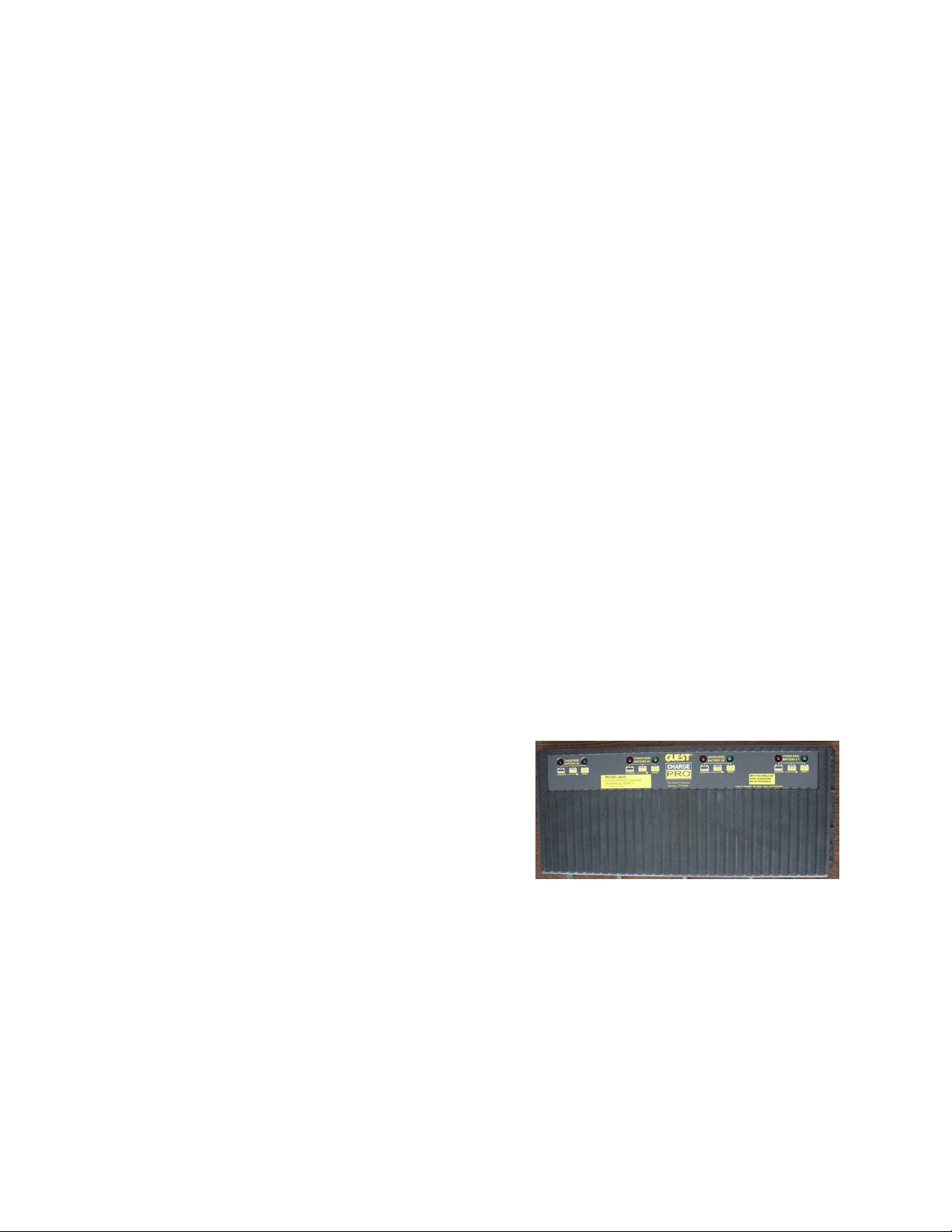
Battery Charger (35 AMP)
The battery charger is installed in the bilge on the aft side
of the forward bulkhead. It is designed to recharge your
batteries and extend the life of your batteries in
applications where the batteries may be stored for long
periods of time.
This battery charger incorporates three 10-amp chargers
and one 5-amp charger into one rugged, waterproof
housing. It provides fast recharging power, as well as
maintenance charging for a cranking or house battery.
Batteries can be fully recharged in just 5 hours.
For operational procedures and information related to the care and maintenance of the battery charger,
please refer to the owner’s manual provided by the manufacturer of the battery charger. When in doubt,
always defer to the battery charger manufacturer’s instructions and/or recommendations.
Battery Management System with Remote
The Target Charge Battery Management Systems replaces the need for a battery switch panel. This
system, also known as the Total Automatic Battery System (TABS) comes equipped with a TABS unit and
a remote control panel.
17
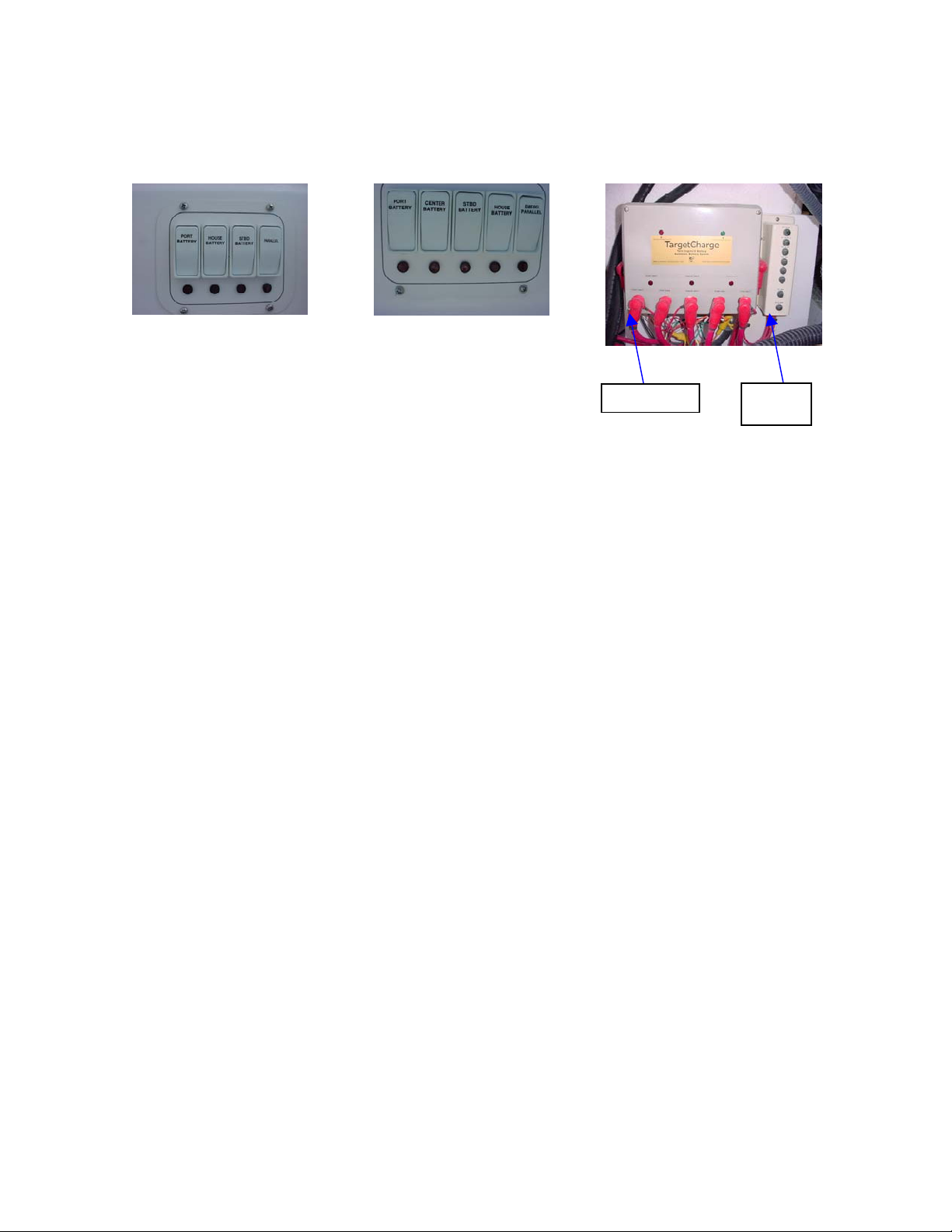
The TABS Unit is installed behind the storage box at the port aft corner of the transom. The remote
control panel is located on the console. The switches on the control panel will vary depending upon the
engine package that was selected.
Twin-engine installation
Triple engine installation
Switches are labeled:
• Port Battery
• House Battery
• Starboard Battery
• Parallel
Switches are labeled:
• Port Battery
• Center Battery
• Starboard Battery
• House Battery
T.A.B.S. Unit
Terminals
Circuit
Breaker
• Emergency Parallel
Pressing a switch on the remote control panel will provide power to the respective component (i.e., Press
the switch labeled port battery to provide power to the port battery, etc.).
There are a series of light indicators on the TABS Unit. When illuminated, these various lights indicate
the following:
• Red light labeled port engine charging house B indicates that the port battery is charging
the house battery
• Green light labeled starboard engine charging house B indicates that the starboard
battery is charging the house battery.
• Red lights labeled port battery, house battery and starboard battery indicate that the
switch on the console control panel is turned on.
When any of the red lights on the remote control panel are illuminated, this indicates that the switch on
the panel is turned on.
If an engine fails to start because of a low or dead start battery, engage and hold the momentary switch
located at the helm for approximately 20 – 30 seconds to start the engine. Then, release the switch. The
prudent operator should frequently check all wire connections to make sure that they are tight, clean and
secure.
Circuit Breakers
Circuit breakers and/or fuses protect the wiring on your 35 Express. In the event a device stops working,
check to see if the circuit breaker is tripped or if the fuse is blown. Breakers are installed in the following
locations:
• The main breakers (DC main and helm main) are located next to the Target
Charger/Battery Management System and are accessible via the storage compartment
hatch located at the port side of the transom (see photo of the Target Charger/Battery
Management System).
• Breakers and/or fuses for the bilge pumps, trim tabs, stereo and accessories are located
above the main breakers.
• Additional breaker switches are also located on the switch panel above the individual
switches.
18
A tripped breaker will protrude or move from its set position indicating that the circuit has been
overloaded. Turn off the device(s) on the circuit, then reset the breaker by pushing in once or by
returning a breaker switch to the “ON” position. If the breaker does not reset or if it resets and then trips
again after the device is turned back on, then a short circuit exists or your device may be damaged,
overloaded, or faulty. Correct the problem and then reset the breaker.
Circuit Breakers – On the switch panel above the individual switches
If the breaker continues to trip and you are certain the device, switch and wiring are in good repair; either
the breaker is faulty or it is too small for the load. Reduce the load or replace the breaker.
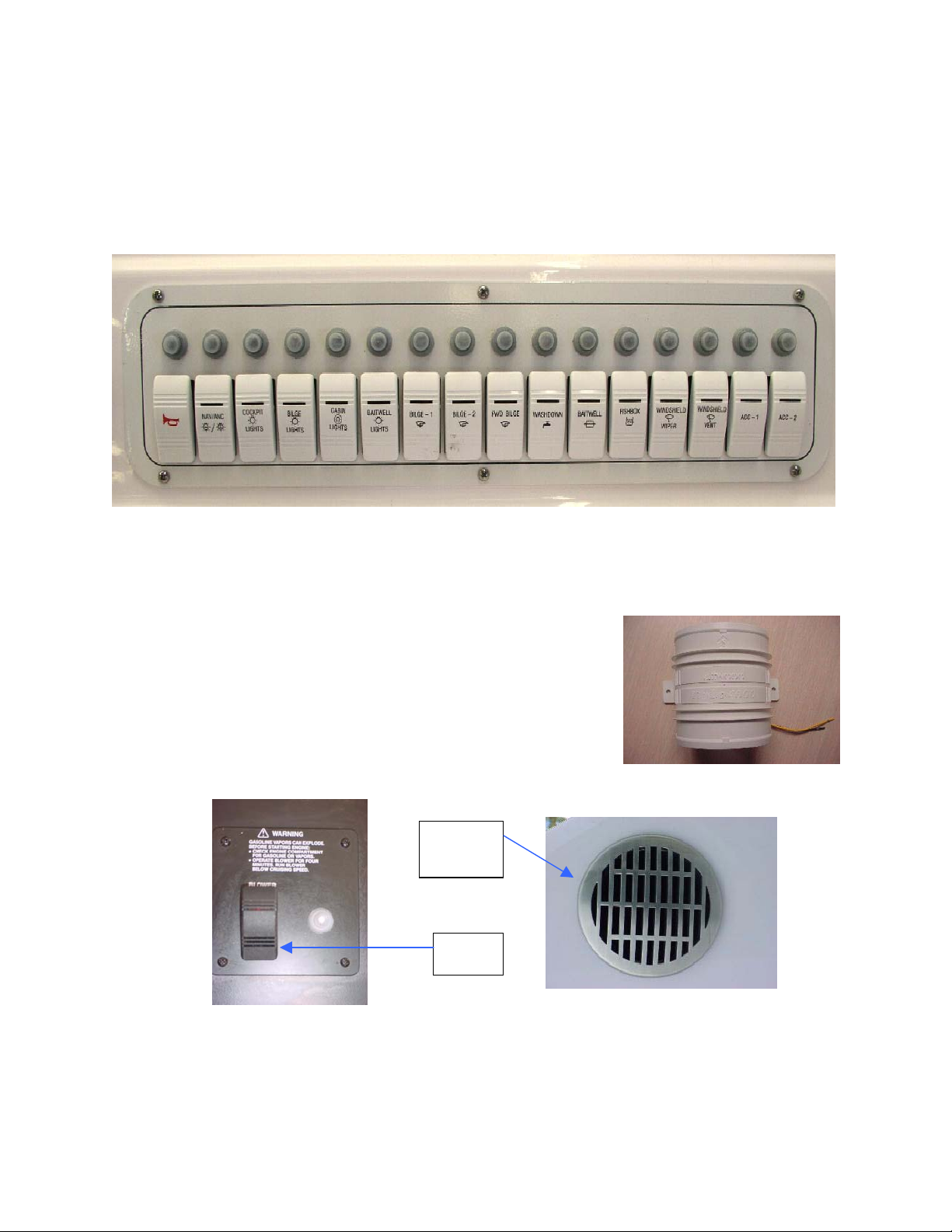
Blower
The blower (standard with the optional generator) is located inside the
bilge and helps keep fresh air circulating in the bilge area. You should
periodically check to make sure that the blower is working properly.
First, confirm that the blower hoses are connected and the blower itself
is secured. Second, locate the blower switch inside the cabin on the
starboard cabin wall and press the switch to the on position. Then, go
back to the bilge area and listen to hear if the blower is running. The
exhaust vents are located on the outside of the transom on the port and
starboard sides. Check to ensure that air is blowing out of the vents.
When finished, go back into the cabin and turn the blower switch off.
Blower
Exhaust
Vent
Blower
Switch
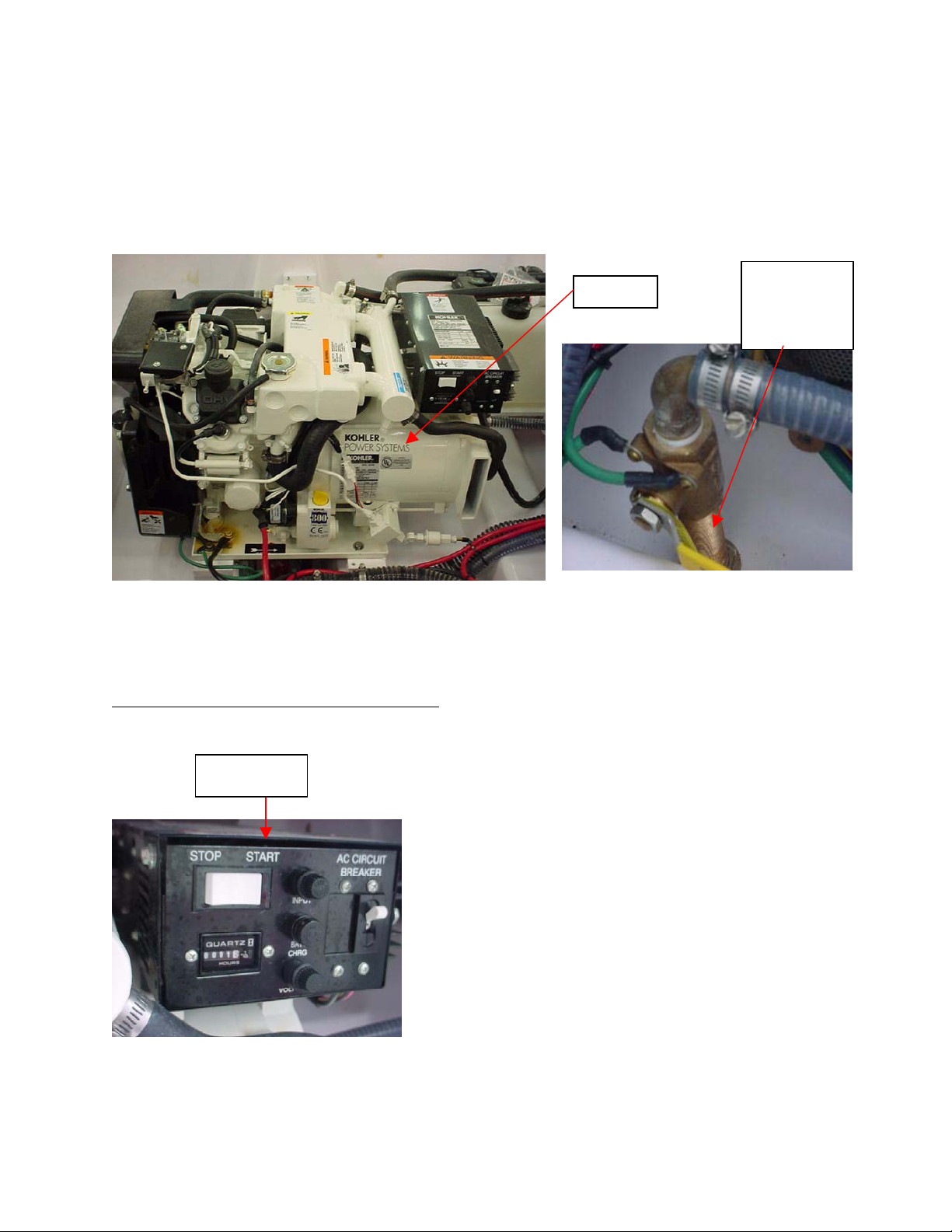
Gas Generator w/Carbon Monoxide Detector (Optional)
If you have selected the optional generator, your vessel will come equipped with a remote start/stop for
the generator, an hour meter and a blower switch.
19
WARNING: The switch for the blower is installed next to the AC/DC panel and should be
turned on for four (4) minutes prior to starting your engines or the generator to ensure
that the bilge is free from any gas fumes. The blower vents are located on the inside
wings of the Euro transom/dive platform.
The generator is installed in the aft area of the bilge and it can be started either direct from the generator
or remotely from the AC panel in the cabin.
Generator
Generator
Seacock
Shown in the
Closed Position
Before attempting to operate the generator, the boat must be in the water or have some type of water
flushing system going into the generator water pick up. The generator seacock is mounted below the port
side hatch on the berth of the mid cabin. Inspect the seacock and ensure that it is open and that the
hoses are all connected. The seacock is open when the lever is in the vertical position.
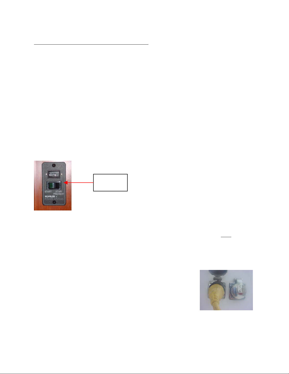
Starting the Generator from the Main Unit - You can start the unit directly from the generator
using the mechanism in the black box located on the upper port side of the generator.
Generator
Black Box
• At the remote control panel for the battery
management system (installed on the
console), press the house battery switch
forward to the on position
• Go into the cabin, locate the AC/DC panel
and move the generator toggle switch to
the on position.
• Locate the blower switch (installed next to
the AC/DC panel) and turn it on. After
allowing the blower to run for a few minutes
and circulate fresh air throughout the bilge,
the generator can be started up.
• Flip the start/stop switch, which is located
on the black box on the front of the
generator, to the “start” position. This
black box also houses an hour meter,
fuses and an AC Circuit breaker.
• To turn the generator off, flip the start/stop
switch to the “stop” position
20
Starting the Generator Remotely from the AC Panel
- The remote start/stop, hour meter and blower
switch are all located on the starboard aft cabin wall next to the AC/DC panel.
When using your optional generator to provide power to the alternating current system, the slide
mechanism on the AC panel needs to be in the “Up” position in order to switch on the generator breaker.
• At the remote control panel for the battery management system (installed on the
console), press the house battery switch forward to the on position
• Go into the cabin, locate the AC/DC panel and move the generator toggle switch to the
on position.
• Locate the blower switch installed next to the AC/DC panel and turn it on. After allowing
the blower to run for a few minutes and circulate fresh air throughout the bilge, the
generator can be started up.
• Locate the generator start switch, which is next to the blower switch. Press the green
side in and hold it until the generator starts up. This may take a couple of attempts
depending on how much fuel is in the fuel tank and if the generator fuel hoses have been
previously run dry.
• When the generator is running, the green light on the start switch will stay illuminated and
water will be coming out of the generator exhaust thru-hull on the outside of the hull.
• To turn the generator off, press and hold the start switch to the right until the generator
stops running. Then turn off the blower.
Remote
Start/Stop for
Generator
The remote start/stop for the generator is equipped
with an hour meter at the top of the switch
Note: The manufacturer of the generator provides the limited warranty for the generator
and most associated parts. Please refer to their owner’s manual and follow their
recommendations for scheduled maintenance and service. To be in accordance with the
terms and conditions of their limited warranty, all service and/or warranty repairs must
be
performed by a repair facility that is authorized to work on their equipment.
Please refer to the owner’s manual provided by the manufacturer of the generator for operational
procedures and for information related to the care and maintenance of their product. When in doubt,
always defer to the generator manufacturer’s instructions and/or recommendations.
Shore Power with Cord
Shore power (50 amp) is used for the operation of AC devices such as your
air conditioner, battery charger, and 110-volt outlets for other appliances.
The shore power package includes a 25 foot long yellow shore power cord.
Note: Before attempting to connect to shore power, take precautions to minimize contact
arcing by making sure that the AC main breaker switch is in the “Off” position prior to
plugging into shore power. The AC main breaker is located on the AC panel on the
starboard aft cabin wall.
21
The shore power outlet is located on the outside of the starboard wing and aft of the starboard portlight.
To connect your shore power system:
• Turn the shore power outlet fitting and lift it up.
• Plug the shore power cord into the outlet on the boat.
• Connect the shore power cord to the receptacle at your marina or dock.
• Only then should you switch the AC main breaker to “On”.
• If the polarity light (red) is on, unplug shore power (first at the shore outlet, then at the
shore power outlet on the boat) and do not use it, until a qualified technician corrects this
potentially dangerous situation.
Please refer to the owner’s manual provided by the manufacturer of the shore power unit for operational
procedures and for information related to the care and maintenance of their product. When in doubt,
always defer to the shore power manufacturer’s instructions and/or recommendations.
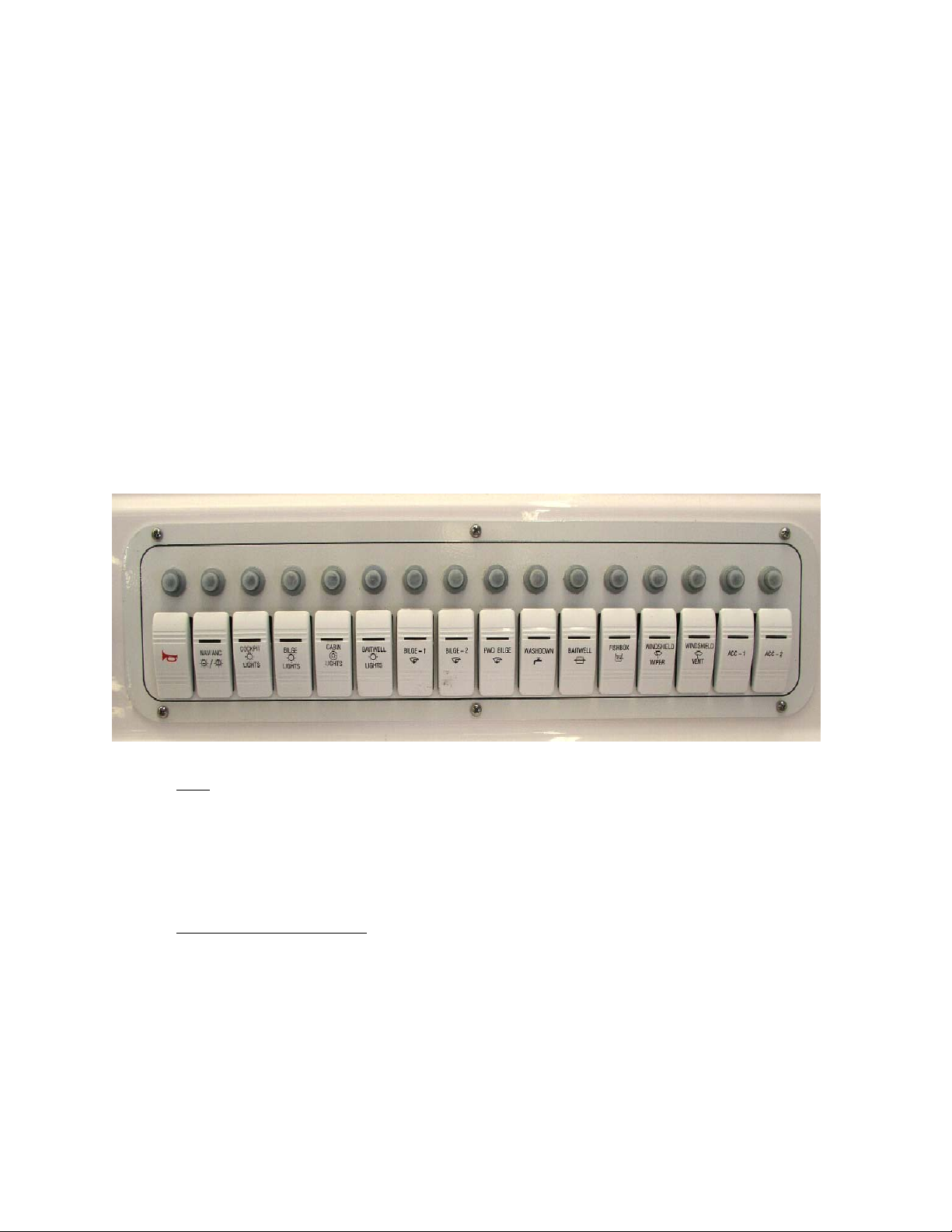
Switch and Breaker Panel
The switch and breaker panel is located on the console and is equipped with 16 switches. The numbers
beneath the photo of the switch and breaker panel shown below correspond with the description provided
for each switch.
1 2 3 4 5 6 7 8 9 10 11 12 13 14 15 16
1 Horn
2 Navigation & Anchor Lights
- The horn is used to signal, warn, or alert other boats, swimmers or people on shore.
Depress the horn switch to the up or forward position to activate the horn. Release the horn
switch to deactivate the horn. Using different sequences of horn blasts indicates different and
sometimes dangerous situations to you or someone around you.
Avoid any horn use without an appropriate purpose. See the Safety Section in this manual
and/or take a safe boating course for more information on the proper use of the horn.
- Locate the Nav. light switch on the instrument panel. This is a 3-
way switch (forward, middle, back/aft) that functions as follows when you press the switch:
• Forward position - Turns on the bow lights and the anchor light. This position
will also activate the red light in your compass.
o If you have Faria gauges on the dash panel, this function will
illuminate the gauge lights.
o If the gauges were provided by the engine manufacturer (i.e.,
Mercury, Honda, etc.), this switch will not illuminate the gauge
lights. Instead, your gauge lights will be illuminated when the
ignition switch is turned on.
22
 Loading...