

Page 1
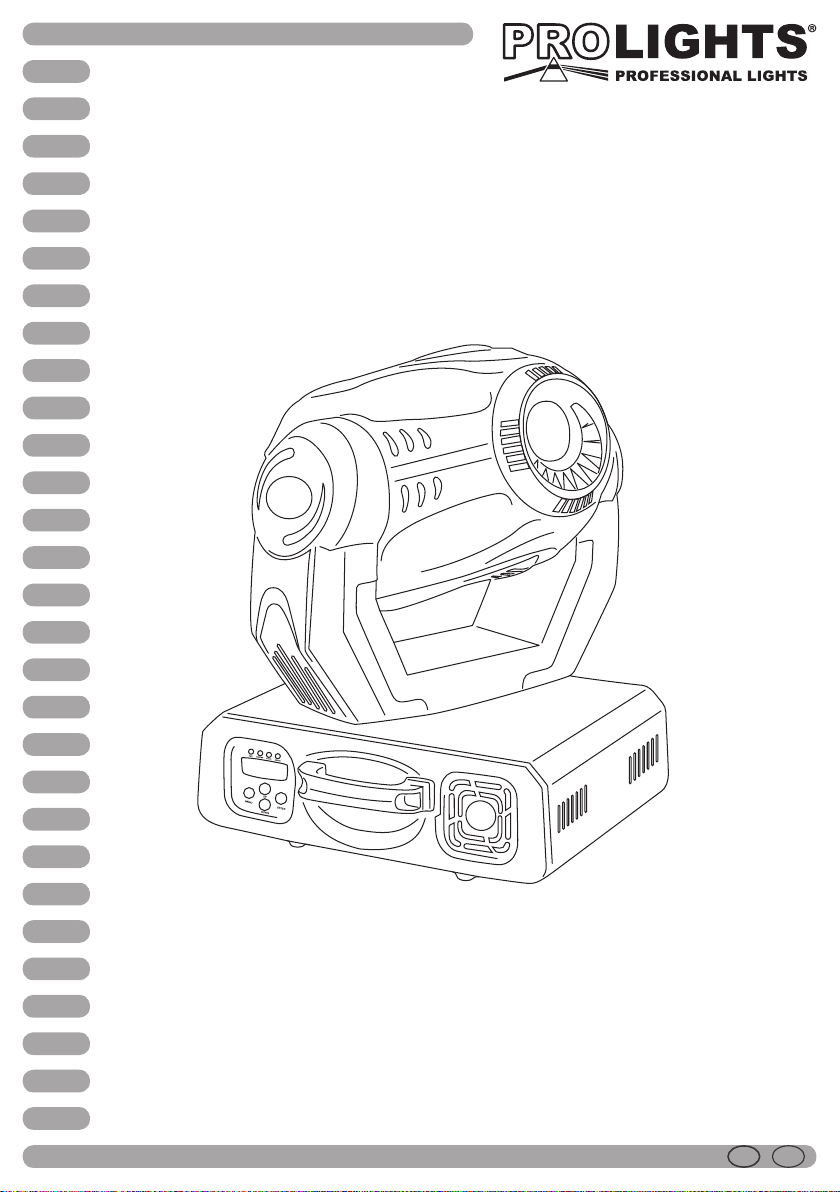
V575SPOT
Moving head
Manuale Utente
User Manual
I GB
Page 2

Music & Lights Srl si riserva ogni diritto di elaborazione in qualsiasi forma delle presenti
istruzioni per l’uso. La riproduzione - anche parziale - per propri scopi commerciali è vietata.
All rights reserved by Music & Lights Srl. No part of this instruction manual may be
reproduced in any form or by any means for any commercial use.
REV.007-10/09
Page 3

INTRODUZIONE
Vi ringraziamo per aver scelto un prodotto PROLIGHTS. Il VISION 575 SPOT è un proiettore motorizzato intelligente
a testa mobile per lampada a scarica da 575W.
INDICE
Sicurezza
Avvertenze generali
Attenzione e precauzioni per l’installazione
Informazioni generali
4
4
4
1 Descrizione e speciche tecniche
1.1 Elementi di comando e collegamenti
1.2 Descrizione
1.3 Specifiche tecniche
5
6
6
2 Installazione
2.1 Lampada
2.2 Installazione o sostituzione lampada
2.3 Montaggio
7
7
7
3 Funzioni e impostazioni
3.1 Funzionamento
3.2 Comando tramite la musica
3.3 Collegamento
3.4 Collegamenti della linea DMX
3.5 Costruzione del terminatore DMX
3.6 Tabella canali DMX (funzionamento a 16 canali)
3.7 Tabella canali DMX (funzionamento a 8 canali)
3.8 Modifica dei parametri di funzionamento
3.9 Preimpostazione dei valori correttivi (Modalità Offset)
3.10 Telecomando EC800 (opzionale)
8
8
8
9
9
10
11
12
13
14
3V575SPOT
4 Manutenzione
4.1 Pulizia sistema ottico e manutenzione
4.2 Sostituzione dei gobos
15
15
Certicato di garanzia
CONTENUTO DELL’IMBALLO:
• V575SPOT
• Staffe di fissaggio con sistema di aggancio rapido a clam-
ps (2 pz.)
• Manuale utente
Tutte le specifiche possono essere variate senza alcuna notifica.
Page 4

V575SPOT4
ATTENZIONE! Prima di eettuare qualsiasi operazione con l’unità, leggere con atten-
zione questo manuale e conservarlo accuratamente per riferimenti futuri. Contiene
informazioni importanti riguardo l’installazione, l’uso e la manutenzione dell’unità.
SICUREZZA
Avvertenze generali
• I prodotti a cui questo manuale si riferisce sono conformi alle Direttive della Comunità Europea e pertanto recano la sigla .
• Il dispositivo funziona con pericolosa tensione di rete 230V~. Non intervenire mai al suo interno al di fuori delle ope-
razioni descritte nel presente manuale; esiste il pericolo di una scarica elettrica.
• È obbligatorio effettuare il collegamento ad un impianto di alimentazione dotato di un’ efficiente messa a terra (apparecchio di Classe I secondo norma EN 60598-1). Si raccomanda, inoltre, di proteggere le linee di alimentazione delle unità
dai contatti indiretti e/o cortocircuiti verso massa tramite l’uso di interruttori differenziali opportunamente dimensionati.
• Le operazioni di collegamento alla rete di distribuzione dell’energia elettrica devono essere effettuate da un installatore elettrico qualificato. Verificare che frequenza e tensione della rete corrispondono alla frequenza ed alla tensione
per cui l’unità è predisposta, indicate sulla targhetta dei dati elettrici.
• L’unità non per uso domestico solo per uso professionale.
• Evitare di utilizzare l’unità:
- in luoghi soggetti ad eccessiva umidità;
- in luoghi soggetti a vibrazioni, o a possibili urti;
- in luoghi a temperatura superiore ai 45°C o inferiori a 2°C.
• Evitare che nell’unità penetrino liquidi infiammabili, acqua o oggetti metallici.
• Non smontare e non apportare modifiche all’unità.
• Tutti gli interventi devono essere sempre e solo effettuati da personale tecnico qualificato. Rivolgersi al più vicino
centro di assistenza tecnica autorizzato.
• Se si desidera eliminare il dispositivo definitivamente,
consegnarlo per lo smaltimento ad un’istituzione locale per il riciclaggio.
Attenzione e preacauzione per l’installazione
• Non guardare direttamente il fascio luminoso.
• Prima di iniziare qualsiasi operazione di manutenzione o pulizia disconnettere l’unità dalla rete di alimentazione.
• Assicurarsi che l’unità sia spenta e che la temperatura delle parti non possa provocare ustioni (attendere almeno 30
minuti dallo spegnimento).
• È assolutamente necessario proteggere l’unità per mezzo di una fune di sicurezza. Nell’eseguire qualsiasi intervento
attenersi scrupolosamente a tutte le normative (in materia di sicurezza) vigenti nel paese di utilizzo.
• Evitare di ostruire l’ingresso e l’uscita dell’aria.
• L’unità deve essere posizionata in modo tale che gli oggetti colpiti dal fascio luminoso siano distanti almeno 1,5 m da essa.
• Mantenere materiali infiammabili ad una distanza di sicurezza dall’unità.
• Non sollevare il proiettore afferrandolo per la parte mobile (testa).
INFORMAZIONI GENERALI
Spedizioni e reclami
Le merci sono vendute “franco nostra sede” e viaggiano sempre a rischio e pericolo del distributore/cliente. Eventuali
avarie e danni dovranno essere contestati al vettore. Ogni reclamo per imballi manomessi dovrà essere inoltrato entro 8
giorni dal ricevimento della merce.
Garanzie e resi
Il prodotto è coperto da garanzia in base alle vigenti normative. Sul sito www.musiclights.it è possibile consultare il testo
integrale delle “Condizioni Generali di Garanzia”. Si prega, dopo l’acquisto, di procedere alla registrazione del prodotto
sul sito www.musiclights.it. In alternativa il prodotto può essere registrato compilando e inviando il modulo riportato
alla fine del manuale. A tutti gli effetti la validità della garanzia è avallata unicamente dalla presentazione del certificato
di garanzia. Music & Lights constata tramite verifica sui resi la difettosità dichiarata, correlata all’appropriato utilizzo, e
l’effettiva validità della garanzia; provvede quindi alla riparazione dei prodotti, declinando tuttavia ogni obbligo di risarcimento per danni diretti o indiretti eventualmente derivanti dalla difettosità.
Le informazioni riportate in questo manuale sono state attentamente controllate.
Music & Lights non si assume, tuttavia, responsabilità derivanti da eventuali inesattezze.
Page 5
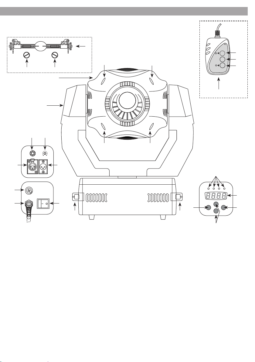
- 1 - DESCRIZIONE E SPECIFICHE TECNICHE
1.1 Elementi di comando e collegamenti
5V575SPOT
22 22
1
2
4 7
5 6
8
9 10
21
Fig. 3
16
16
16 16
3 3
CONTROLLER
STAND
BY
20
FUNCTION
19
MODE
18
Fig. 2
17
15
SOUNDSLAVEMASTERDMX
14
11 13
UP
MENU ENTER
DOWN
1. Testa mobile;
2. Braccio girevole;
3. Maniglie;
4. Presa di collegamento per il telecomando EC800;
5. DMX OUT(XLR a 3 poli):1=massa, 2=DMX-, 3=DMX+;
6. DMX IN(XLR a 3 poli):1=massa, 2=DMX-, 3=DMX+;
7. Regolatore della sensibilità del microfono interno.
Girando in senso orario, la sensibilità aumenta;
8. Portafusibile: sostituire un fusibile difettoso solo
con uno dello stesso tipo;
9. (230V~/50Hz), cavo di alimentazione senza spina;
10. Interruttore on/off;
11. Tasto MENU per chiamare il menu d’impostazione;
12. Tasti UP e DOWN per selezionare un’impostazione del menù;
13. Tasto ENTER per confermare un’impostazione del
menù;
14. Display;
15. LED di controllo per la modalità di funziona-
Fig.1
12
mento: DMX=è acceso se all’ingresso DMX
IN è presente un segnale DMX di comando;
MASTER=modalità MASTER: comando mediante
il telecomando(opzionale) o il microfono integrato; SLAVE=modalità SLAVE: comando mediante
un secondo V575SPOT; SOUND=si accende brevemente se l’unità cambia colore, disegno o movimento in seguito ad un segnale musicale;
16. Viti per aprire la testa mobile;
17. Telecomando EC800 (opzionale) (fig.2);
18. TastoMODE per cambiare fra modalità Show1 a
Show4;
19. Tasto FUNCTION;
20. Tasto STAND BY per la funzione Blackout (testa mobile in posizione di partenza e diaframma chiuso);
N. B.: Per poter usare il telecomando, all’ingresso DMX
IN non deve essere presente alcun segnale DMX.
21. Lampada (non inclusa);
22. Viti lampada;
Page 6

V575SPOT6
1.2 Descrizione
Il V575SPOT si distingue per le eccezionali prestazioni. La lampada a scarica da 575W, il sofisticato sistema
ottico ad elevata resa cromatica e luminosa, i movimenti precisi e lineari ed il design moderno ed elegante
fanno del V575SPOT un proiettore particolarmente adatto a tutte le applicazioni nel settore dell’illuminazione professionale.
1.3 Speciche tecniche
Proiettore a testa mobile per lampada a scarica 575W con attacco Sfc10-4 a innesto rapido (cod. 8001134PL
inclusa).
• Lamp On/Off: tramite pannello di controllo o via DMX.
• Reset dell’unità: riavvio da pannello di controllo o via DMX.
• Sistema ottico: lenti antiriflesso ad alta definizione con trattamento acromatico, parabola riflettente in
vetro con profilo sferico, angolo di proiezione max 14°.
• Focus: messa a fuoco motorizzata da 2m all’infinito.
• Controllo: protocollo DMX 512 tramite XLR 3 poli, 16 canali a 16 bit o 8 canali a 8 bit.
• Dimmer meccanico: lineare 0 -100%.
• Strobo/Shutter: effetto strobo (1-10 flash per secondo) ed effetti di dissolvenza con velocità regolabile.
Apertura e blackout istantanei.
• Iris: diaframma ad iride motorizzato apertura da 0 a 100%.
• Ruota colore: 9 colori dicroici + open. Effetto rainbow. Cambio colore con opzione di sincronismo
blackout.
• Ruota gobos statici: 9 gobos intercambiabili + open.
• Ruota gobos rotanti: 7 gobos (di cui 2 dicroici) indicizzati e intercambiabili + open.
• Controllo gobos: rotazione continua ed effetto shake. Cambio gobo con opzione di sincronismo blackout.
• Prisma: a 3 facce con rotazione bidirezionale a velocità variabile.
• Movimento Pan/Tilt: escursione 540°/270°. Risoluzione 8 o 16bit (movimento fine). Controllo posizione
Pan/Tilt tramite encoder digitale e riposizionamento automatico in caso di urti o spostamenti accidentali.
• Interfaccia utente: pannello di controllo con display LED a 4 caratteri per impostazione unità, diagnostica, vita lampada e modalità funzionamento.
• Easy show: programmi preimpostati con modalità automatico/musicale attivabile da pannello di controllo o mediante telecomando EC800 (opzionale).
• Raffreddamento: ad aria filtrata forzata, protezione da surriscaldamento. Per operazioni silenziose settaggio ventole.
• Corpo: in polimeri ad alta resistenza, colore nero, maniglie ergonomiche laterali per trasporto.
• Sospensione e fissaggio: qualsiasi posizione per mezzo di supporti omega con sistema di aggancio
“quick lock”.
• Alimentazione: 230V~ 50Hz con ballast elettromagnetico, cavo di alimentazione senza terminale.
• Dimensioni (LxAxP):427x478x369 mm.
• Peso: 27 kg.
Page 7
7V575SPOT
- 2 - INSTALLAZIONE
2.1 Lampada
Si raccomanda l’uso di lampade 575W attacco SFc10-4. Assicurarsi che la lampada sia compatibile con il
voltaggio dell’impianto elettrico usato. Se lampada viene fatta operare con un voltaggio superiore al suo
voltaggio nominale potrebbe essere danneggiata o la sua durata notevolmente ridotta.
2.2 Installazione o sostituzione lampada
Per installare la lampada, osservare le seguenti istruzioni (la lampada può raggiungere temperature molto
alte, attendere il raffreddamento dell’unità prima di eseguire qualsiasi tipo di operazione. Una lampada
danneggiata deve essere sostituita immediatamente).
1. Disconnettere la spina di alimentazione dell’unità, svitare le 4 viti e togliere la scocca superiore della testa
mobile. Svitare le 2 viti zigrinate sulla copertura della lampada fra la ventola di raffreddamento superiore e il
retro della testa mobile. A questo punto si può togliere la copertura della lampada e si vede il portalampada.
2. Nel caso di sostituzione della lampada svitare le due viti zigrinate della vecchia lampada e togliere la
lampada dalla sua sede.
3. Non toccare la lampadina a mani nude, se ciò accade, pulire la lampada con alcool denaturato ed asciugare con un panno che non lasci pelucchi. Afferrare la nuova lampada alle due estremità (non al vetro) e
inserirla nel portalampada (vedi fig. 3). Avvitare bene le due viti zigrinate.
4. Rimettere la copertura della lampada nonché la scocca del contenitore e avvitarli bene.
• La lampadina contiene piccole quantità di sostanze nocive all’ambiente (per es. mercurio), e quindi in
Europa deve essere trattata come rifiuto tossico. In altri paesi si devono rispettare le norme nazionali.
• Al massimo dopo 1,25 volte la durata media della lampadina occorre sostituirla perché con l’uso aumenta il rischio di scoppio in seguito alle modifiche strutturali del vetro di quarzo.
L’unità è equipaggiata con un contaore che può essere usato per determinare le ore di funzionamento della
lampadina. Segnalare l’indicazione del contatore quando si sostituisce la lampadina.
• Se la lampadina scoppia durante l’utilizzo si consiglia di allontanarsi dall’unità per escludere completamente i
rischi alla salute per i vapori di mercurio che si libereranno; provvedere ad una buona aerazione dell’ambiente.
2.3 Montaggio
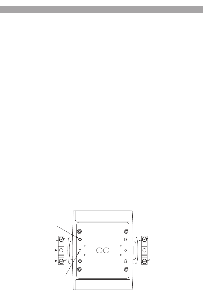
Il V575SPOT può essere collocato su un piano solido. Inoltre, grazie alle possibilità di fissaggio della piastra alla
base (vedi fig. 4), l’unità può essere montata anche a testa in giù, su una traversa. Per il fissaggio occorrono dei
supporti robusti per il montaggio. Avvitare i supporti direttamente nelle filettature M10 (27) oppure fissarli
alle staffe di montaggio (25) in dotazione, i cui perni (26), come si vede nell’illustrazione, vengono inseriti nelle
apposite sedi (24) della piastra dove vengono bloccati con una rotazione in senso orario (fino all’arresto). L’area
di collocazione deve avere una stabilità sufficiente a supportare almeno 10 volte il peso dell’unità.
24
25
26
27
Fig. 4
Page 8
V575SPOT8
- 3 - FUNZIONI E IMPOSTAZIONI
3.1 Funzionamento
Inserire la spina del cavo rete (9) in una presa di rete (230 V~/50 Hz). Accendere l’unità con l’interruttore (10).
La testa mobile e tutti i motori di comando si mettono in una precisa posizione di partenza. Poco dopo, il
V575SPOT è pronto. Dopo l’uso spegnere l’unità con l’interruttore.
N.B. : Come fonte di luce viene usata una lampada a scarica elettrica. Se l’unità viene spenta o se la corrente
viene interrotta solo brevemente, la lampada non si riaccende subito. É necessario che si raffreddi affinchè
possa essere accesa nuovamente.
3.2 Comando tramite la musica
1. Per comandare il V575SPOT tramite il microfono integrato, non si deve collegare l’ingresso DMX INPUT
(6). Se a quell’ingresso non è presente alcun segnale di comando DMX, il LED giallo MASTER (15) è acceso
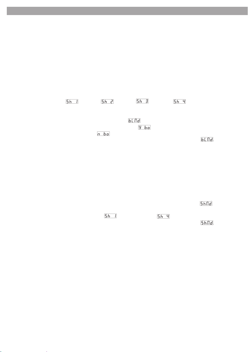
e il display (14) segnala (Show 1), (Show 2), (Show 3) o (Show 4).
IMPORTANTE! Se il proiettore a testa mobile rimane nella sua posizione di partenza e il raggio di luce viene
mascherato occorre disattivare la funzione blackout tramite il menù:
a) Premere il tasto MENU (11) finché sul display appare (blackout mode).
b) Premere il tasto ENTER (13). Il display lampeggia e indica (yes blackout).
c) Con il tasto DOWN o UP (12) passare a (no blackout).
d) Per memorizzare la scelta premere il tasto ENTER. Il display indica per alcuni secondi . Successivamente appare di nuovo il modo di funzionamento selezionato. Se il tasto ENTER non viene premuto entro 8
secondi, l’unità ritorna all’impostazione precedente.
2. Il modo di funzionamento Show 1 è previsto per l’unità collocata sul pavimento. L’angolo di rotazione intorno all’asse orizzontale è di 210° max. Nel modo di funzionamento Show 2, previsto per il montaggio al
soffitto, l’angolo è di 90° max. Il modo di funzionamento Show 3 è previsto per la collocazione dell’unità
su un palcoscenico e diretto verso il pubblico. L’angolo di rotazione orizzontale è di 160° max. e quello
verticale di 90° max. (60° sopra l’orizzonte e 30° sotto l’orizzonte). Nel modo di funzionamento Show 4,
previsto nuovamente per il montaggio al soffitto, l’angolo di rotazione orizzontale è di 160° max. e quello
verticale di 90° max. (75° in avanti e 15° all’indietro).
a) Per cambiare fra Show1 a Show4 premere il tasto MENU tante volte finchè sul display appare (show mode).
b) Premere il tasto ENTER (13). Il display lampeggia.
c) Con il tasto DOWN o UP (12) cambiare fra per Show 1 fino a per Show 4.
d) Per memorizzare la scelta premere il tasto ENTER. Il display indica per alcuni secondi . Successivamente appare di nuovo il modo di funzionamento selezionato e il programma comincia a svolgersi. Se il
tasto ENTER non viene premuto entro 8 secondi, l’unità ritorna all’impostazione precedente.
3. Impostare il regolatore SENSITIVITY per la sensibilità del microfono in modo tale che il ritmo della musica
venga riprodotto in modo ottimale dai movimenti del raggio di luce nonché dal cambio dei disegni e dei
colori. La maggiore sensibilità si ha con il regolatore girato completamente a destra. Quando cambia il colore, il disegno o il movimento in seguito ad un segnale musicale, il led verde Sound si accende brevemente.
N.B. : Se si modifica il volume dell’impianto di musica occorre adattare anche la sensibilità del microfono con
l’aiuto del relativo regolatore.
3.3 Collegamento
Si possono collegare più unità per comandare, per mezzo del microfono dell’unità principale (Master), tutte
le unità secondarie (Slave) nello stesso ritmo.
1. Collegare l’uscita DMX OUT dell’unità principale con l’ingresso DMX IN della prima unità secondaria.
2. Collegare l’uscita DMX OUT della prima unità secondaria con l’ingresso DMX IN della seconda unità secondaria ecc.
3. Non appena le unità secondarie sono connesse e il segnale di comando dell’unità principale è presente,
il LED rosso SLAVE, delle unità secondarie, rimane acceso. I movimenti delle unità secondarie possono
essere sincronizzati oppure opposti all’unità principale.
Page 9
9V575SPOT
a) Per scegliere la modalità di movimento, premere tante volte il tasto MENU (11) sull’unità secondaria finché il display indica (slave mode).
b) Premere il tasto ENTER (13). Il display lampeggia.
c) Con il tasto DOWN o UP (12) permette di selezionare fra (normal) modalità di movimento sincronizzato e (2 light show) modalità di movimento opposto.
d) Per memorizzare la scelta premere il tasto ENTER. Il display indica per alcuni secondi . Successivamente appare di nuovo il modo di funzionamento selezionato e il programma comincia a svolgersi. Se il
tasto ENTER non viene premuto entro 8 secondi, l’unità ritorna all’impostazione precedente.
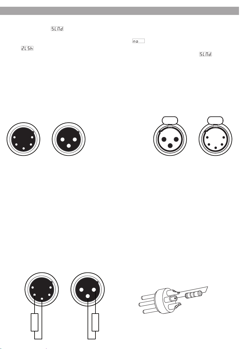
3.4 Collegamenti della linea DMX
La connessione DMX è realizzata con connettori standard XLR. Utilizzare cavi schermati, 2 poli ritorti, con impedenza 120Ω e bassa capacità. Per il collegamento fare riferimento allo schema di connessione riportato di seguito:
1 5
2 4
3
DMX - INPUT
Spina XLR
Pin1 : Massa - Schermo
Pin2 : - Negativo
3
Pin3 : + Positivo
Pin4 : N/C
Pin5 : N/C
DMX - OUTPUT
1
21 2
3
Presa XLR
5
432
1
ATTENZIONE
La parte schermata del cavo (calza) non deve mai essere collegata alla terra dell’impianto; ciò comporterebbe malfunzionamenti delle unità e dei controller. Per passaggi lunghi può essere necessario l’inserimento
di un amplificatore DMX. In tal caso, è sconsigliato utilizzare nei collegamenti cavo bilanciato microfonico
poichè non è in grado di trasmettere in modo affidabile i dati di controllo DMX.
• Collegare l’uscita DMX del controller con l’ingresso DMX della prima unità;
• Collegare, quindi, l’uscita DMX con l’ingresso DMX della successiva unità; l’uscita di quest’ultima con
l’ingresso di quella successiva e via dicendo finchè tutte le unità sono collegate formando una catena.
• Per installazioni in cui il cavo di segnale deve percorrere lunghe distanze è consigliato inserire sull’ultima
unità una terminazione DMX.
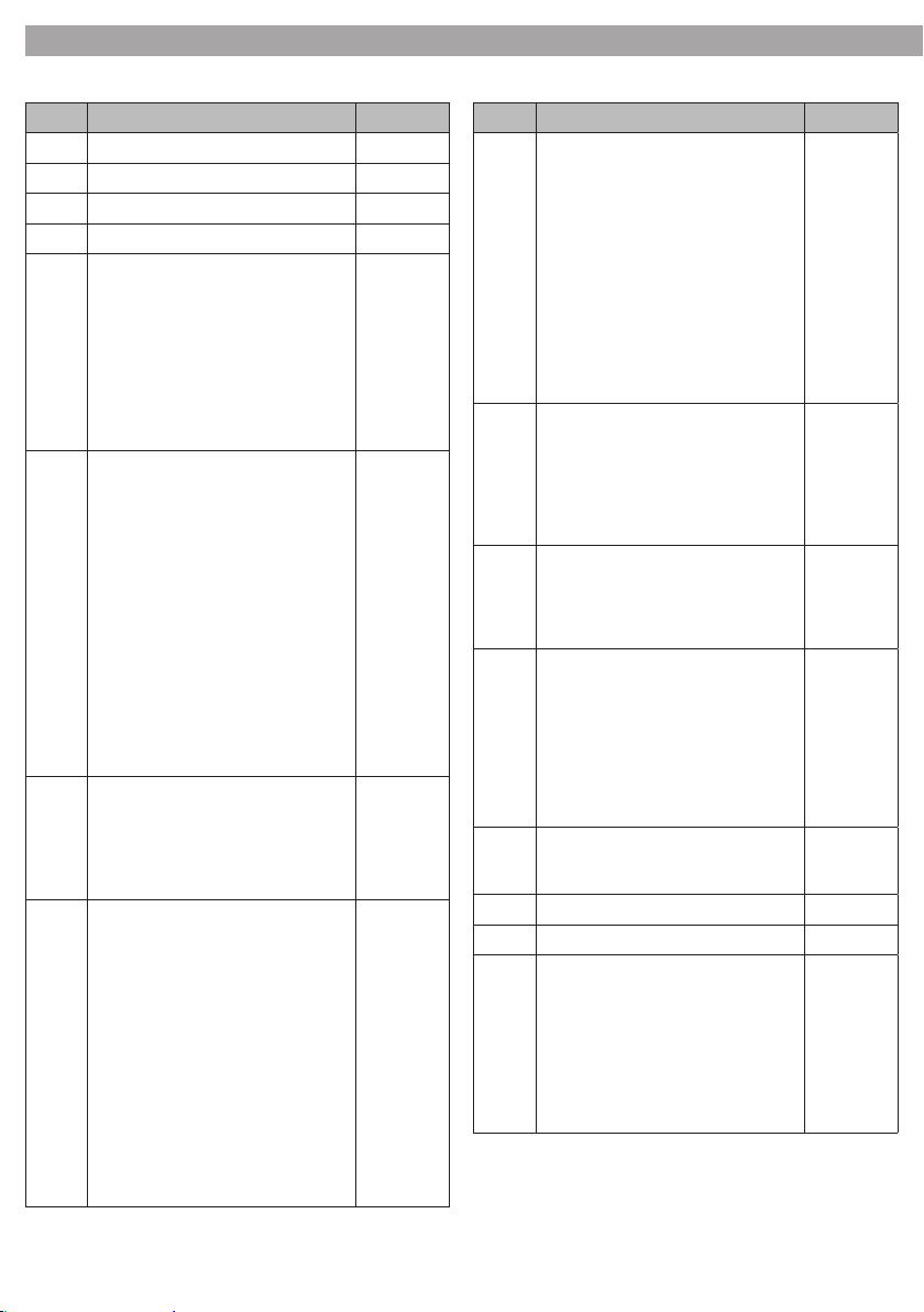
3.5 Costruzione del terminatore DMX
La terminazione evita la probabilità che il segnale DMX512, una volta raggiunta la fine della linea stessa venga
riflesso indietro lungo il cavo, provocando, in certe condizioni e lunghezze, la sua sovrapposizione al segnale originale e la sua cancellazione. La terminazione dev’essere effettuata, sull’ultima unità della catena, con connettori XLR
a 5 pin o 3 pin, saldando una resistenza di 120Ω (minimo 1/4W) tra i terminali 2 e 3, così come indicato in figura.
1 5
2 4
3
1 2
3
2
3
1
120 Ω 120 Ω
Esempio:
connettore XLR a 3 pin
Page 10
V575SPOT10
3.6 Tabella canali DMX (funzionamento a 16 canali)
Canale Modalità di funzionamento a 16 canali Valore DMX
1 Pan 000-255
2 Tilt 000-255
3 Pan / Tilt speed 000-255
4 Dimmer 000-255
5 Shutter / Shaking
Shutter chiuso (blackout)
Shutter aperto
Stroboscopio Lento - Veloce
Effetto oscillazione ruota Gobo 1
Lento - Veloce
Effetto oscillazione ruota Gobo 2
Lento - Veloce
Shutter aperto
6 Colore 1
Bianco
Verde
Magenta
Azzurro
Giallo
Rosso
Blue
UV viola
Verde chiaro
Rosa
Cambiamento costante di colore
Veloce - Lento
Lento - Veloce
(direzione opposta)
7 Iris
Diametro: largo - stretto
Lento chiuso - Veloce aperto
Lento aperto - Veloce chiuso
Aperto / Chiuso: da lento a veloce
8 Ruota Gobo 1
No Gobo
Gobo1
Gobo2
Gobo3
Gobo4
Gobo5
Gobo6
Gobo7
Gobo8
Gobo9
Cambiamento costante del gobo:
Veloce - Lento
Lento - Veloce
000-007
008-015
016-131
132-185
186-239
240-255
000-012
013-025
026-038
039-050
051-063
064-076
077-088
089-101
102-114
115-127
128-191
192-255
0-127
128-169
170-212
213-255
000-012
013-025
026-038
039-050
051-063
064-076
077-088
089-101
102-114
115-127
128-191
192-255
Canale Modalità di funzionamento a 16 canali Valore DMX
9 Ruota Gobo 1
No Gobo
Gobo10
Gobo11
Gobo12
Gobo13
Gobo14
Gobo15
Gobo16
Cambiamento costante del gobo:
Veloce - Lento
Lento - Veloce
10 Rotazione ruota Gobo 1
Angolo di rotazione del Gobo Rotazi-
one in senso orario
Veloce - Lento
Rotazione in senso anti-orario
Lento - Veloce
11 Prisma
No effetto
Prisma effetto 1
Prisma effetto 2
12 Rotazione Prisma
No rotazione Prisma
Rotazione in senso orario
Veloce - Lento
No rotazione Prisma
Rotazione in senso anti-orario
Lento - Veloce
No rotazione Prisma
13 Focus
Vicino - Lontano 0-255
14 Pan - 16 Bit (regolazione) 000-255
15 Tilt - 16 Bit (regolazione) 000-255
16 Reset / Lampada On-Off
No effetto
Lampada on
No effetto
DMX reset
No effetto
Lampada off
No effetto
000-015
016-031
032-047
048-063
064-079
080-095
096-111
112-127
128-191
192-255
000-127
128-191
192-255
000-085
086-170
171-255
000-009
010-120
121-134
135-245
246-255
0-129
130-139
139-199
200-209
210-229
230-239
240-255
Page 11
3.7 Tabella canali DMX (funzionamento a 8 canali)
Canale Modalità di funzionamento a 8 canali valore DMX
1 Pan 000-255
2 Tilt 000-255
3 Shutter
4 Ruota Gobo
Shutter chiuso (blackout)
Shutter aperto
Stroboscopio Lento - Veloce
Oscillazione
Effetto Oscillazione Ruota Gobo 1
Lento - Veloce
Effetto Oscillazione Ruota Gobo 1
Lento - Veloce
Shutter aperto
No Gobo
Gobo1
Gobo2
Gobo3
Gobo4
Gobo5
Gobo6
Gobo7
Gobo8
Gobo9
Gobo10
Gobo11
Gobo12
Gobo13
Gobo14
Gobo15
Gobo16
Gobo10 + Gobo1
Gobo10 + Gobo3
Gobo10 + Gobo5
Gobo10 + Gobo7
Gobo10 + Gobo9
Gobo13 + Gobo1
Gobo13 + Gobo3
Gobo13 + Gobo5
Gobo13 + Gobo7
Gobo13 + Gobo9
Gobo15 + Gobo1
Gobo15 + Gobo3
Gobo15 + Gobo5
Gobo15 + Gobo7
Gobo15 + Gobo9
Cambiamento costante del Gobo
(1-9)
Veloce - Lento
Lento - Veloce (direzione opposta)
Cambiamento costante del Gobo2
(10-16)
Veloce - Lento
Lento - Veloce (direzione opposta)
000-007
008-015
016-131
132-185
186-239
240-255
000-003
004-007
008-011
012-015
016-019
020-023
024-027
028-031
032-035
036-039
040-043
044-047
048-051
052-055
056-059
060-063
064-067
068-071
072-075
076-079
080-083
084-087
088-091
092-095
096-099
100-103
104-107
108-111
112-115
116-119
120-123
124-127
128-159
160-187
188-219
220-255
11V575SPOT
Canale Modalità di funzionamento a 8 canali valore DMX
5 Colori
Bianco
Verde
Magenta
Azzurro
Giallo
Rosso
Blue
UV viola
Verde chiaro
Rosa
Cambiamento
Veloce - Slow
Lento - Veloce
(direzione opposta)
6 Rotazione ruota Gobo
Angolo di rotazione del Gobo
Rotazione in senso orario
Veloce - Lento
Rotazione in senso anti-orario Lento
- Veloce
Iris
Diametro: Largo - Stretto
Lento chiuso - Veloce aperto
Lento aperto - Veloce chiuso
Aperto / Chiuso:
da Lento a Veloce
7 Prisma
no effetto
Prisma
Prisma effetto 1
Rotazione in senso orario
Veloce - Lento
Rotazione in senso anti-orario Lento
- Veloce
Prisma effetto 2
Rotazione in senso orario
Veloce - Lento
Rotazione in senso anti-orario Lento
- Veloce
Dimmer
8 Focus
Vicino - Lontano 0-255
000-012
013-025
026-038
039-050
051-063
064-076
077-088
089-101
102-114
115-127
128-191
192-255
000-063
064-095
096-127
128-191
192-212
213-234
235-255
000-015
016-031
032-055
056-079
080-103
104-127
128-255
Page 12
V575SPOT12
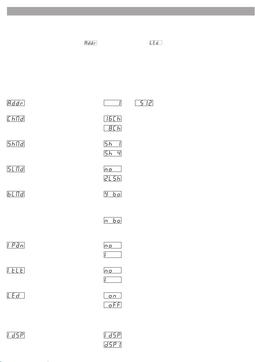
3.8 Modica dei parametri di funzionamento
Attraverso il menù, si possono modificare i seguenti parametri.
1. Premere il tasto MENU (11) tante volte finché sul display si vede il punto desiderato del menù.
2. Nei primi otto punti del menù ( indirizzo di start fino a spegnimento del display) confermare
la selezione con il tasto ENTER (13). Quindi con i tasti DOWN o UP (12) effettuare l’impostazione e memorizzarla entro 8 secondi con il tasto ENTER. Per i restanti punti del menù dove il display lampeggia se
vengono chiamati, il funzionamento verrà descritto in modo particolareggiato.
3. Per passare al punto successivo del menù, premere il tasto MENU oppure selezionare il punto desiderato
del menù con i tasti UP e DOWN (12).
4. Se con un punto del menù selezionato non si preme alcun tasto nel giro di 8 secondi, il menù si spegne.
L’ ordine dei punti del menù è il seguente:
Impostazione dell'indirizzo di start:
Modalità a 16/8 canali DMX:
Modalità Show:
. . .
Modalità Slave:
. . .
Modalità Blackout:
Rotazione della testa mobile (Pan): normale
Inclinazione della testa mobile (Tilt):
. . .
16 canali
8 canali
show 1
show 4
normale
2 light show
Blackout on. Se alla presa DMX INPUT non è presente alcun
segnale DMX di comando, la testa mobile si porta nella
posizione di partenza e il diaframma viene chiuso. È possibile
il comando tramite il telecomando.
Blackout off. Se non è presente alcun segnale di comando
DMX, l’unità viene comandata tramite il microfono integrato
oppure, eventualmente, tramite il telecomando.
rotazione in senso opposto
normale
movimento in senso opposto
LED Display on/off: display on
display off
(Display off). Dopo l’uscita dal menù è indicato per 30 secondi ca. l’indirizzo oppure il modo di funzionamento; quindi il
display si spegne. Non appena vine premuto uno dei tasti (11-13), si accende nuovamente.
Rappresentazione sul display: normale
reverse di 180° (per il montaggio al soffitto)
Con il tasto ENTER si cambia l’impostazione. Il display lampeggia per 8 secondi.Quindi il menù si spegne.
Page 13
13V575SPOT
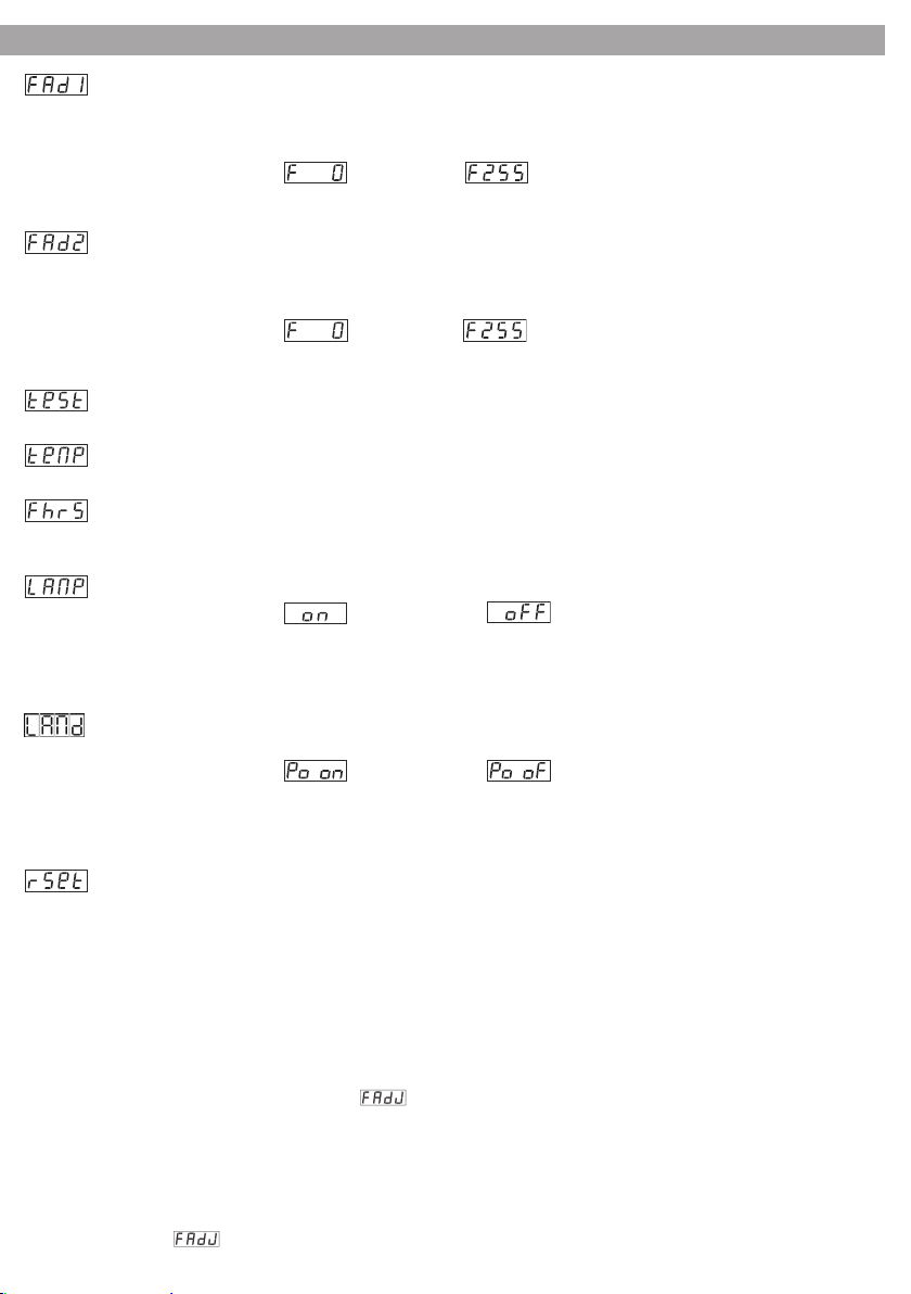
Impostazione del fuoco per la ruota gobo 1. Dopo aver premuto il tasto ENTER, la testa si porta dapprima nella
posizione verticale; con ogni ulteriore pressione del tasto ENTER si scelgono le quattro direzioni principali
dell’orizzontale. Nella posizione che si avvicina di più alla direzione prevista per la proiezione, il fuoco per i
gobo della ruota 1 può essere regolato con i tasti DOWN e UP:
normal
. . .
Confermare l’impostazione con il tasto ENTER. Il valore viene memorizzato e preso in considerazione nei programmi Show 1– 4.
Impostazione del fuoco per la ruota gobo 2. Dopo aver premuto il tasto ENTER, la testa si porta dapprima nella
posizione verticale; con ogni ulteriore pressione del tasto ENTER si scelgono le quattro direzioni principali
dell’orizzontale. Nella posizione che si avvicina di più alla direzione prevista per la proiezione, il fuoco per i
gobo della ruota 2 può essere regolato con i tasti DOWN e UP:
normal
. . .
Confermare l’impostazione con il tasto ENTER. Il valore viene memorizzato e preso in considerazione nei programmi Show 1– 4.
Autotest. Dopo aver premuto il tasto ENTER si svolge l’autotest. Per terminare il test premere il tasto MENU. Il
punto successivo del menù lampeggia per 8 secondi. Quindi il menù si spegne.
Temperatura ambiente della lampada Dopo aver premuto il tasto ENTER viene indicata la temperatura ambiente della lampada (in °C).
Contaore (Fixture Hours). Dopo aver premuto il tasto ENTER, il display indica le ore di funzionamento. Per
ritornare al modo precedente di funzionamento premere il tasto MENU. Il punto successivo del menù lampeggia per 8 secondi. Quindi il menù si spegne.
Lamp on/off. Dopo aver premuto il tasto ENTER, con i tasti UP o DOWN si può accendere o spegnere la lampada:
lampada on
Confermare la scelta con il tasto ENTER.
N. B.: Dopo lo spegnimento, la lampada a scarica elettrica, ancora calda, non può essere riaccesa subito. La nuova accensione può quindi tardare alcuni minuti.
Lamp on/off all’accensione dell’unità. Dopo aver premuto il tasto ENTER, con i tasti UP o DOWN si può accendere o spegnere la lampada:
lampada on lampada off
Confermare la scelta con il tasto ENTER.
N. B.: Dopo lo spegnimento, la lampada a scarica elettrica, ancora calda, non può essere riaccesa subito. La nuova accensione può quindi tardare alcuni minuti.
Premendo il tasto ENTER viene effettuato il reset: la testa mobile ritorna brevemente nella sua posizione di
partenza e il raggio di luce viene mascherato. Dopodiché l’unità ritorna nel modo precedente di funzionamento
3.9 Preimpostazione dei valori correttivi (Modalità Oset)
Per la regolazione fine della posizione della testa mobile, delle due ruote gobo e della ruota di colori, si
possono qui effettuare delle impostazioni correttive.
1. Tenere premuto il tasto MENU (11) per non meno di 5 secondi. Viene indicato il primo punto del menù.
2. Premere il tasto MENU tante volte finché il punto desiderato del menù appare sul display.
3. Confermare la scelta con il tasto ENTER (13).
Quindi con il tasto DOWN o UP (12) effettuare l’impostazione e memorizzarla entro 8 secondi con il tasto
ENTER. La procedura diversa per il punto (Focus adjustment = Regolazione del fuoco).
4. Per saltare al punto successivo del menù premere il tasto MENU e selezionare il punto desiderato con il
tasto UP e DOWN (12).
5. Se dopo la selezione di un punto del menù, per 8 secondi non si preme alcun altro tasto, il menù si spegne.
N. B. : Se viene chiamato questo menù, la testa mobile si porta sempre nella posizione verticale. Se tale direzione della proiezione oppure il fuoco attuale non sono adatte per le impostazioni correttive volute, chiamare
dapprima il punto (Focus adjustment = Regolazione del fuoco) e scegliere un’altra direzione per la proiezione oppure cambiare la distanza focale. L’ordine qui rappresentato è quello del punti del menù:
lampada off
Page 14
V575SPOT14
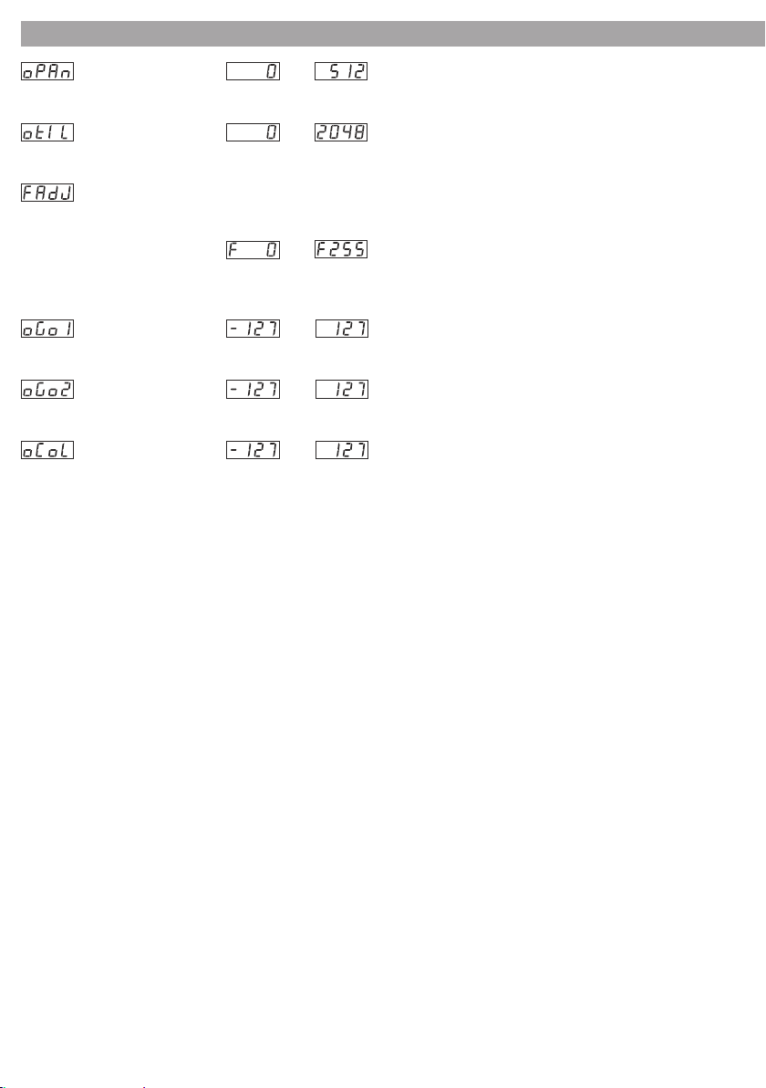
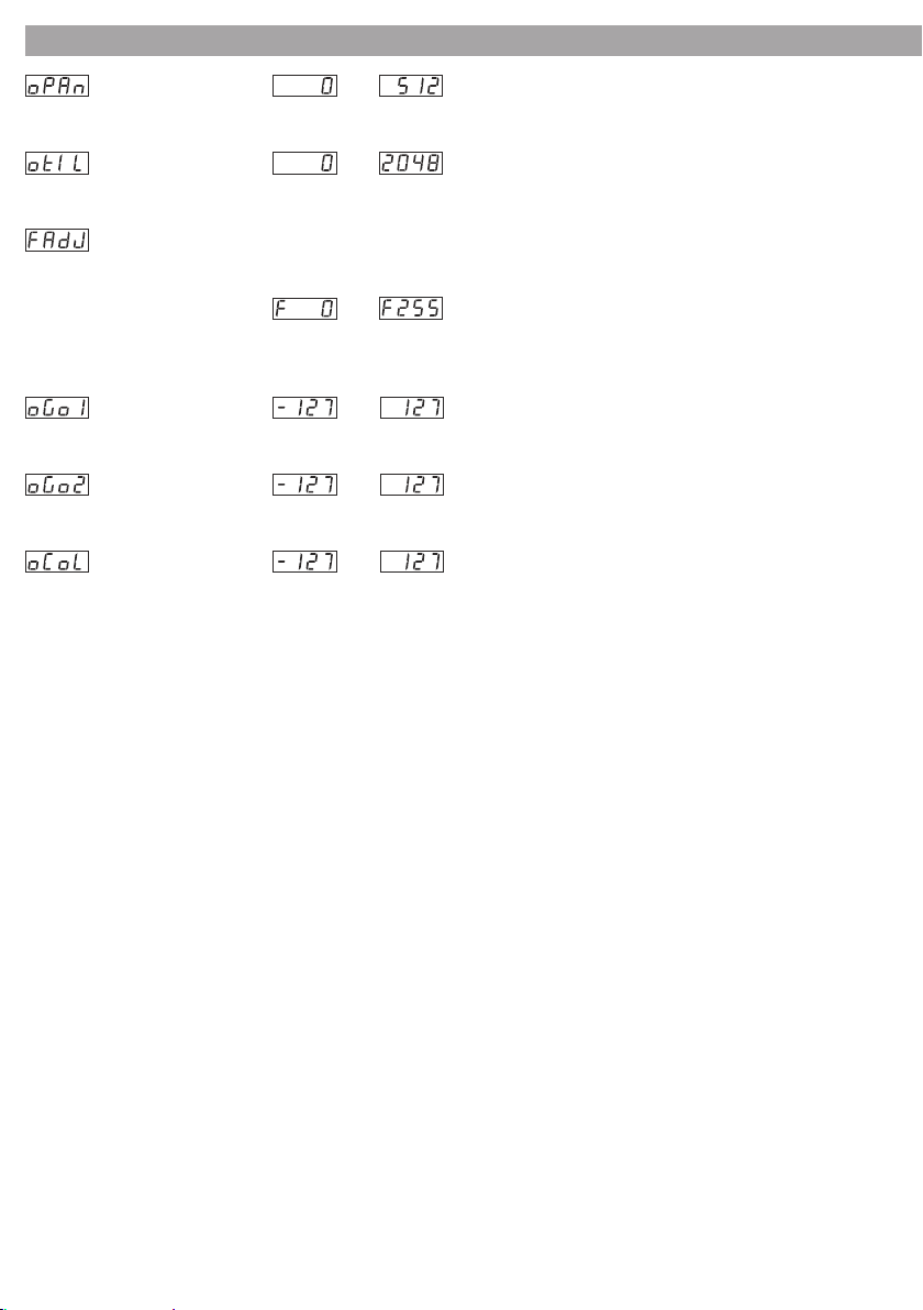
Offset PAN:
Correzione fine per la posizione orizzontale della testa mobile
Offset TILT:
Correzione fine per la posizione verticale della testa mobile
Impostazione del fuoco. Dopo aver premuto il tasto ENTER, la testa si porta dapprima nella posizione verticale; con
ogni ulteriore pressione del tasto ENTER si scelgono le quattro direzioni principali dell’orizzontale. Nella posizione
che si avvicina di più alla direzione prevista per la proiezione, il fuoco può essere regolato con i tasti DOWN e UP:
Premendo il tasto MENU, l’impostazione viene accettata. La regolazione qui effettuata serve solo per poter meglio impostare gli altri parametri di questo menù. Per il funzionamento è senza importanza.
Offset ruota gobo 1
Correzione fine per la posizione gobo nella ruota 1.
Offset ruota gobo 2
Correzione fine per la posizione gobo nella ruota 2.
Offset ruota colori
Correzione fine per la posizione del filtro nella ruota colori
. . .
. . .
. . .
. . .
. . .
. . .
3.10 Telecomando EC800 (opzionale)
Con il telecomando opzionale (vedi fig.2) si possono controllare diverse funzioni.
1. Collegare il telecomando con la presa REMOTE CONTROL (4).
2. L’ingresso DMX non deve essere collegato; il LED giallo MASTER (15) deve essere acceso.
3. All’uscita DMX si possono collegare altri V575SPOT per movimenti telecomandati sincronizzati con l’unità principale.
4. Con il tasto STAND BY si può attivare e disattivare la funzione Blackout. Se la funzione è attivata, il LED
vicino al tasto è acceso. La testa mobile ritorna nella posizione di partenza e il diaframma viene chiuso.
5. Con il tasto MODE (18) selezionare la modalità:
a) Modalità SOUND 1 (il LED vicino al tasto non è acceso).
Tenendo premuto il tasto FUNCTION (19) si può attivare uno dei tre effetti stroboscopici:
- Effetto stroboscopico con colori e disegni che cambiano;
- Effetto stroboscopico con luce bianca; nell’unità secondarie, l’effetto è in sincronia;
- Effetto stroboscopico con luce bianca; nell’ unità secondari, l’effetto è opposto.
b) Modalità SOUND 2 (il LED lampeggia lentamente).
Premendo il tasto FUNCTION si può attivare uno dei 4 modi di funzionamento Show (vedi “Comando tramite la musica”). Premendo di nuovo il tasto FUNCTION è attivato il modo di funzionamento Show successivo.
c) Modalità SLOW/SOUND 3 (il LED rimane acceso).
Con questo modo di funzionamento solo il movimento del raggio di luce viene comandato dalla musica.
Per cambiare il colore e il disegno, azionare il tasto FUNCTION. Con una pressione breve del tasto si passa al
colore successivo, con una pressione più lunga al disegno successivo.
d) Modalità POSITION (il LED lampeggia velocemente).
Tenendo premuto il tasto FUNCTION, si determina dapprima la posizione orizzontale della testa. Quindi, tenendo premuto ancora il tasto FUNCTION si determina la posizione verticale della testa. Infine, tenendo ancora premuto il tasto FUNCTION si imposta il valore per il dimmer o per un effetto di prisma. Le posizioni e i
valori di dimming saranno fissati dapprima per il master. Quindi seguono le impostazioni per gli apparecchi
slave. Durante le modalità SOUND 1 e SOUND 3, il raggio d’azione della testa mobile dipende dal modo di
funzionamento Show 1, Show 2, Show 3 o Show 4 selezionato nel menù oppure attraverso il telecomando
nella modalità SOUND 2 e indicato sul display (14).
Page 15
15V575SPOT
- 4 - MANUTENZIONE
4.1 Pulizia sistema ottico e manutenzione
• Durante gli interventi, assicurarsi che l’area sotto il luogo di installazione sia libera da personale non qualificato.
• Spegnere l’unità, scollegare il cavo di alimentazione ed aspettare finché l’unità non sia raffreddata.
• Tutte le viti utilizzate per l’installazione dell’unità e le sue parti dovrebbero essere assicurate saldamente
e non dovrebbero essere corrose.
• Alloggiamenti, elementi di fissaggio e di installazione (soffitto, truss, sospensioni) dovrebbero essere
totalmente esenti da qualsiasi deformazione.
• Quando una lente ottica è visibilmente danneggiata a causa di rotture o graffi profondi, deve essere sostituita.
• I cavi di alimentazione devono essere in condizione impeccabile e dovrebbero essere sostituiti immedia-
tamente nel momento in cui anche un piccolo problema viene rilevato.
• Al fine di proteggere l’unità da surriscaldamento, le ventole di raffreddamento (e nel caso) le aperture di
ventilazione, devono essere pulite mensilmente.
• L’interno del dispositivo deve essere pulito ogni anno utilizzando un aspirapolvere o un getto d’aria.
• Si dovrebbe procedere, ad intervalli regolari, alla pulizia della lente per asportare polvere, fumo e altre par-
ticelle. Solo così, la luce può essere irradiata con la luminosità massima. Per la pulizia usare un panno morbido, pulito e un detergente per vetri come si trovano in commercio. Quindi asciugare le parti delicatamente.
Attenzione: consigliamo che la pulizia interna sia eseguita da personale qualificato!
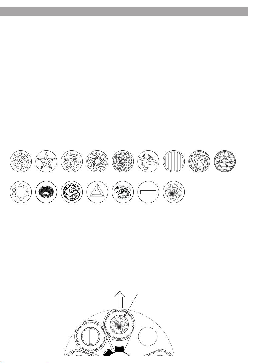
Gobos
1 2 3 4 5 6 7 8 9
Fig. 5
10 11 12 13 14 15 16
4.2 Sostituzione dei gobos
I gobos rotanti nella seconda ruota possono essere cambiati e sostituiti, per esempio, con propri gobos:
1. Staccare la spina dalla presa di rete e fare raffreddare l’unità per 15 minuti circa.
2. Togliere la parte superiore della testa mobile (1) dopo aver svitato le viti (16).
3. Girare la ruota, come indicato nella figura 6, in modo che il gobo da sostituire si trovi in alto.
4. Togliere l’anello di sicurezza (28) sul gobo con un utensile adatto e prelevare il gobo.
Non svitare le viti sul portagobos perché tengono insieme il cuscinetto a sfere!
5. Inserire il nuovo gobo nel portagobos fissarlo con l’anello di sicurezza. Se il gobo ha un lato più scuro o
più opaco, tale lato deve essere orientato verso la lampada.
6. Sistemare il portagobos nella ruota in modo che venga fissato sotto l’anello di sicurezza (28) .
7. Chiudere il contenitore della testa mobile nuovamente con le viti.
28
Fig. 6
Page 16

Page 17

V575SPOT
INTRODUCTION
Thank you for purchasing a PROLIGHTS product. The V575SPOT is a moving head projector for the creative lighting of
shows and places of entertainment with 575W discharge lamp.
INDEX
Safety
General instructions
Warnings and installation precautions
General information
1 Description and technical specications
1.1 Operating elements and connections
1.2 Description
1.3 Technical specifications
2 Installation
2.1 Lamp
2.2 Inserting o replacing the lamp
2.3 Mounting
3 Functions and settings
3.1 Operation
3.2 Music control
3.3 Linking
3.4 Connection of the DMX line
3.5 Construction of the DMX termination
3.6 DMX control (16 channels operation)
3.7 DMX control (8 channels operation)
3.8 Changing the operating parameters
3.9 Presetting of corrective values (offset mode)
3.10 Remote control EC800 (optional)
2
2
2
3
4
4
5
5
5
6
6
6
7
7
8
9
10
11
12
1
4 Maintenance
4.1 Cleaning the unit and maintenance
4.2 Replacement of the Gobos
Warranty
PACKING CONTENT:
• V575SPOT
• Fixing bars with having a fast-locking clamp system (2 pz.)
• User manual
Design and specifications are subject to change without notice
13
13
Page 18
2
WARNING! Before carrying out any operations with the unit, carefully read this instruction
manual and keep it with cure for future reference. It contains important information about the
installation, usage and maintenance of the unit.
V575SPOT
SAFETY
General instructions
• The products referred to in this manual conform to the European Community Directives and are therefore marked with .
• The unit is supplied with hazardous network voltage (230V~). Leave servicing to skilled personnel only. Never make
any modifications on the unit not described in this instruction manual, otherwise you will risk an electric shock.
• Connection must be made to a power supply system fitted with efficient earthing (Class I appliance according to
standard EN 60598-1). It is, moreover, recommended to protect the supply lines of the units from indirect contact and/
or shorting to earth by using appropriately sized residual current devices.
• The connection to the main network of electric distribution must be carried out by a qualified electrical installer. Check that
the main frequency and voltage correspond to those for which the unit is designed as given on the electrical data label.
• This unit is not for home use, only professional applications.
• Never use the fixture under the following conditions:
- in places subject to excessive humidity;
- in places subject to vibrations or bumps;
- in places with a temperature of over 45°C or less than 2°C.
• Make certain that no inflammable liquids, water or metal objects enter the fixture.
• Do not dismantle or modify the fixture.
• All work must always be carried out by qualified technical personnel. Contact the nearest sales point for an inspection
or contact the manufacturer directly.
• If the unit is to be put out of operation definitively,
take it to a local recycling plant for a disposal which is not harmful to the environment.
Warnings and installation precautions
• Never look directly at the light beam.
• Before starting any maintenance work or cleaning of the unit, cut off power from the main supply.
• Make certain that the fixture is off and the temperature of the components cannot cause burns (wait at least 30 min-
utes after switching off).
• Always additionally secure the projector with the safety rope. When carrying out any work, always comply scrupulously
with all the regulations (particularly regarding safety) currently in force in the country in which the fixture’s being used.
• Avoid blocking air intakes and outputs.
• The unit needs to be positioned so that the objects hit by the beam of light are at least 1,5 m from the unit.
• Keep any inflammable material at a safe distance from the fixture.
• Do not lift the fixture holding it by the moving part (the head).
GENERAL INFORMATION
Shipments and claims
The goods are sold “ex works” and always travel at the risk and danger of the distributor. Eventual damage will have to be
claimed to the freight forwarder. Any claim for broken packs will have to be forwarded within 8 days from the reception
of the goods.
Warranty and returns
The guarantee covers the fixture in compliance with existing regulations. You can find the full version of the “General
Guarantee Conditions” on our web site www.musiclights.it. Please remember to register the piece of equipment soon
after you purchase it, logging on www.musiclights.it. The product can be also registered filling in and sending the form
available on your guarantee certificate. For all purposes, the validity of the guarantee is endorsed solely on presentation
of the guarantee certificate. Music & Lights will verify the validity of the claim through examination of the defect in relation to proper use and the actual validity of the guarantee. Music & Lights will eventually provide replacement or repair of
the products declining, however, any obligation of compensation for direct or indirect damage resulting from faultiness.
The information provided in this manual has been carefully checked.
However Music & Lights is not responsible for any possible inaccuracy.
Page 19
V575SPOT
- 1 - DESCRIPTION AND TECHNICAL SPECIFICATIONS
1.1 Operating elements and connections
3
22 22
1
2
4 7
5 6
8
9 10
21
Fig. 3
16
16
16 16
3 3
CONTROLLER
STAND
BY
20
FUNCTION
19
MODE
18
Fig. 2
17
15
SOUNDSLAVEMASTERDMX
14
11 13
UP
MENU ENTER
DOWN
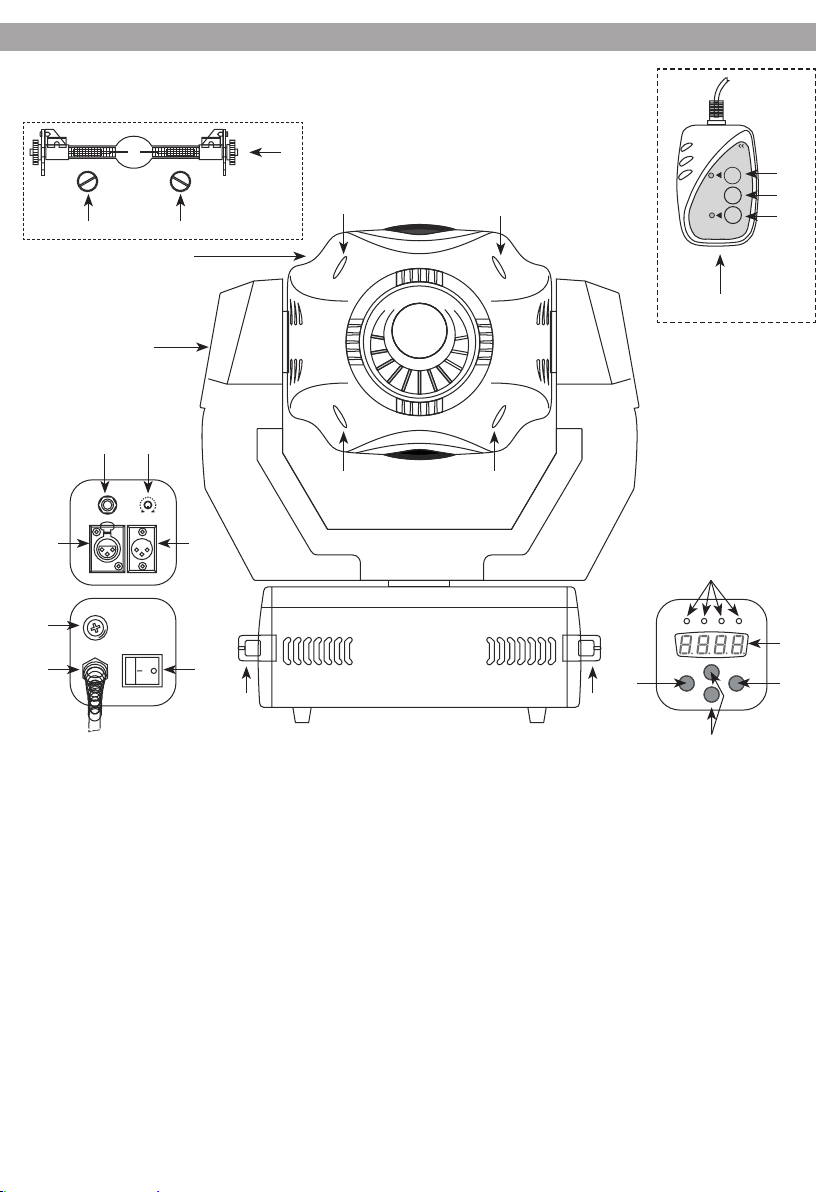
1. Pan head;
2. Rotary arm;
3. Carrying handles;
4. Connection jack for the remote control EC800;
5. DMX OUT (3-pole XLR): 1=ground, 2=DMX-, 3=DMX+;
6. DMX IN (3-pole XLR): 1=ground, 2=DMX-, 3=DMX+;
7. Control for the sensitivity of the integrated microphone. By turning the control clockwise, the
sensitivity will be increased.;
8. Main fuse holder. Replace a burnt-out fuse by
one of the same type only;
9. (230 V~/50 Hz), connection cable without plug;
10. Power switch;
11. Button MENU to call the adjusting menu;
12. Buttons UP and DOWN to select a setting in the
menu;
13. Button ENTER to confirm a menu setting;
14. Display;
15. Indicating LEDs for the operating mode:
Fig.1
12
DMX = lights up in case of a DMX control signal
present at the DMX INPUT;
MASTER = master mode: control via the remote
control (opzional) or the integrated microphone;
SLAVE = slave mode; control via a second V575SPOT;
SOUND = shortly lights up when the colour, the
pattern, or the movement of the unit is changed
by a music signal;
16. Screws for opening the pan head;
17. Remote control EC800 (opzional) (fig.2);
18. Button MODE to switch between the modes
Show 1 to Show 4;
Note: For operation via the remote control, no DMX
signal must be present at the input DMX IN.
19. Button FUNCTION;
20. Button STAND BY for the function Blackout (pan
head in its starting position and shutter closed);
21. Lamp ( not included);
22. Screws for lamps;
Page 20

4
1.2 Description
V575SPOT distinguish itself for the exceptional performances. The 575W discharge lamp, the powerful light
output with vivid colours of the innovative optical system, the fast and high precision movements and the
modern and elegant design make the V575SPOT especially suitable for any professional lighting application.
1.3 Technical specications
Moving head projector for 575W discharge lamp (item. no. 8001134PL included) with double-ended Sfc104 socket.
• Lamp On/Off: through control panel or via DMX.
• Unit reset: through control panel or via DMX.
• Optical System: high definition anti-reflection lenses with achromatic coating, parabolic glass reflector
with spherical profile, 14° max beam angle.
• Focus: 2m to infinity motorised focusing lens.
• Control: DMX 512 protocol through 3 poles XLR connection, 16 channels at 16 bits or 8 channels at 8 bits.
• Mechanical dimmer: 0 – 100% linear dimming.
• Strobe/Shutter: strobe effect (1-10 flashes per second) and fading effects with adjustable speed. Instant
open and blackout.
• Iris: motorised 0 -100% iris diaphragm.
• Color wheel: 9 dichroic colors + open. Rainbow effect plus color change with synchronized blackout
option.
• Static gobo wheel: 9 fixed interchangeable gobos + open.
• Rotating gobo wheel: 7 rotating gobos (2 of which dichroic) indexed and interchangeable + open.
• Gobo control: continuous rotation and shake effect. Gobo change with synchronized blackout option.
• Prism: 3-facet prisms rotating in both directions at different speeds.
• Pan and tilt range: 540°/270° range. 8 or 16bit resolution (fine movement). Pan/Tilt positioning by digital
encoder for automatic repositioning in case of collisions or accidental movements.
• User Interface: 4-digit multi-function LED display to control unit addressing, diagnostics, lamp life and
general settings.
• Easy show: built-in programs with automatic/sound activated mode enabled by LED control panel or by
EC800 remote control (not included).
• Cooling: Filtered forced air, protection against overheating. Fan control for quieter operation.
• Body: high resistance polymer case in black color with ergonomic handles on each side for easy trans-
portation.
• Suspension and fixing: any position by means of omega clamps with “quick lock” system.
• Power Supply: 230V~ 50Hz, electromagnetic ballast, connection cable without plug.
• Dimensions (WxHxD):427x478x369 mm.
• Weight: 27 kg.
V575SPOT
Page 21
V575SPOT
5
- 2 - INSTALLATION
2.1 Lamp
We recommend that you use 575W with a base SFc10 (575W). Make sure that the lamp you use is compatible with local voltage. If the lamp is operated with a voltage surpassing its nominal operating voltage, it can
be damaged or its service life reduced considerably.
2.2 Inserting o replacing the lamp
Please proceed as follows to replace the lamp (the lamp gets very hot during operation, so let it cool down sufficiently before you attempt to dismount it! Lamps that have been damaged must be replaced immediately.)
1. Disconnect the power supply; unscrew the four screws and remove the upper shell of the housing of the
pan head. Release the two knurled screws on the lamp cover between the upper fan and the rear side of
the pan head. Then remove the lamp cover. The lampholder will be visible.
2. For replacing a lamp, release the two knurled nuts of the old lamp and remove the lamp from its lampholder.
3. Seize the new lamp on both ends (do not touch the glass tube) and place it into the lampholder (see
fig.3). Fasten the two knurled nuts of the lamp.
4. Replace the lamp cover and the shell of the housing and tighten the screws.
• The lamp listed here contains slight quantities of harmful substances which may affect the environment
(e. g. mercury) and therefore requires a disposal as special waste in Europe. In other countries, the corrisponding national regulations must be observed.
• Replace the lamp at the latest after its 1.25 fold average lifetime because with increasing service life the
risk of a lamp explosion will considerably increase due to structural transformation of the quartz glass.
The unit is provided with a working hour meter. This may be used to determine the lighting time of the
lamp. Note down the count of the meter when replacing the lamp menu item working hour meter.
• After a lamp explosion during operation, everyone should leave the immediate surroundings of the
lamp as a precaution to completely exclude a health risk caused by the mercury vapours being released;
ensure a good ventilation of the room.
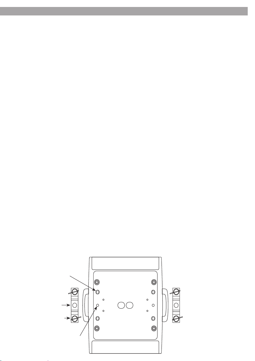
2.3 Mounting
The V575SPOT may be set up on a solid and even surface. By means of the fixing facilities of the base plate,
the unit can also be mounted upside down to a cross arm. The base plate is shown in figure 4. For fixing,
stable mounting clips are required. Directly screw the clips into the M10 threads (27) or fasten them to the
supplied mounting brackets (25). According to the figure, the bolts (26) of the brackets are placed into the
openings (24) provided in the base plate and turned clockwise until they lock (to the stop). The mounting
place must be of sufficient stability and be able to support a weight of 10 times of the unit’s weight.
24
25
26
27
Fig. 4
Page 22
6
V575SPOT
- 3 - FUNCTIONS AND SETTINGS
3.1 Operation
Connect the plug of the main cable (9) to a socket (230 V~/50 Hz). Switch on the unit with the power switch.
The pan head and all control motors will go to a defined starting position. Shortly after that the V575SPOT
is ready for operation. After operation, switch off the unit with the power switch.
Note: A discharge lamp serves as a light source. If, for a short time only, the unit is switched off or disconnected from the power supply, the lamp will not immediately light up again. To be able to ignite again, it
must cool down for some time.
3.2 Music control
1. To control the V575SPOT exclusively via the integrated microphone, do not connect the DMX INPUT (6).
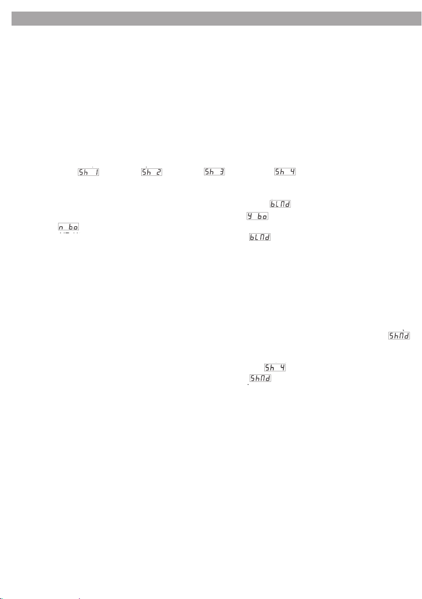
If no DMX control signal is present at this input, the yellow LED MASTER (15) will light up and the display
(14) will Show (Show 1), (Show 2), (Show 3), or (Show 4).
IMPORTANT! If the pan head remains in its starting position and the shutter is closed, the function blackout
must be switched off via the menu:
a) Press the button MENU (11) so many times until the display shows (blackout mode).
b) Press the button ENTER (13). The display will flash and show (yes blackout).
c) Switch to (no blackout) with the button DOWN or UP (12).
d) To memorize, press the button ENTER. The display will show for a few seconds. Then the selected
operating mode will reappear. If the button ENTER is not actuated for 8 seconds, the unit will return to its
previous adjustment.
2. The operating mode Show 1 is provided for placing the unit on the floor. The maximum rotation angle
around the horizontal axis is 210°. For the operating mode Show 2 provided for ceiling mounting, the maximum is 90°. The operating mode Show 3 is provided for setting up the unit on stage towards the audience.
The horizontal rotation angle is 160° and the vertical rotation angle 90° (60° above the horizon and 30°
below the horizon). For the operating mode Show 4 also provided for ceiling mounting, the maximum
horizontal angle is 160° and the maximum vertical rotation angle 90° (75° to the front and 15° to the rear).
a) To switch between Show 1 to 4, press the button MENU (11) so many times until the displayshows
(show mode).
b) Press the button ENTER (13). The display starts flashing.
c) With the button DOWN or UP (12), switch between for Show 1 to for Show 4.
d) To memorize, press the button ENTER. The display will show for a few seconds. Then the selected
operating mode will reappear and the programme sequence will start. If the button ENTER is not actuated
for 8 seconds, the unit will return to its previous adjustment.
3. Adjust the control SENSITIVITY (7) for the microphone sensitivity so that the dynamic power of the music will be reproduced in an optimum way by the movements of the light beam and the change of the
colours. The highest sensitivity is set with the control at the right stop. Each time the colour, pattern, or
movement is changed by a music signal, the green LED SOUND (11) will light up shortly.
Note: When changing the volume of the music system, the microphone sensitivity must be adapted accordingly via the rotary control.
3.3 Linking
Several units can be interconnected in order to control all further slave units to the same rhythm via the
microphone of the master unit.
1. Connect the DMX OUT (5) of the master unit via a 3-pole XLR cable to the DMX IN (6) of the first slave unit.
2. Connect the DMX OUTPUT of the first slave unit to the DMX INPUT of the second slave unit, etc.
3. As soon as the control signals from the master unit are present at the slave units, their red LED SLAVE
(15) will constantly light up. The movements of the slave units may be in sync with the master unit or be
exactly opposite to it (e. g. if only one slave unit is used).
a) To switch between movement in sync and opposite movement, press the button MENU (11) on the slave
Page 23
V575SPOT
7
unit so many times until the display shows (slave mode).
b) Press the button ENTER (13). The display
c) With the button DOWN or UP, switch between (normal) for movement in sync and (2 light
show) for opposite movement.
d) To memorize, press the button ENTER. The display will show for a few seconds. Then the selected operating mode will reappear ( for movement in sync or for opposite movement) and the programme sequence will start. If the button ENTER is not actuated for 8 seconds, the unit will return to its previous adjustment.
3.4 Connection of the DMX line
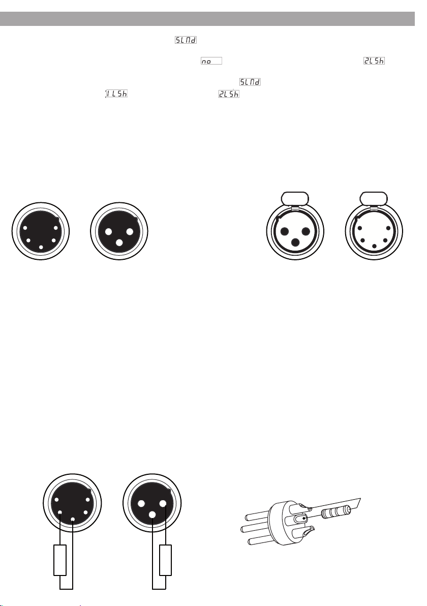
DMX connection employs standard XLR connectors. Use shielded pair-twisted cables with 120Ω impedance and low capacity. The following diagram shows the connection mode:
1 5
2 4
3
DMX - INPUT
XLR plug
Pin1 : GND - Shield
Pin2 : - Negative
3
Pin3 : + Positive
Pin4 : N/C
Pin5 : N/C
DMX - OUTPUT
XLR socket
1
21 2
3
5
432
1
ATTENTION
The screened parts of the cable (sleeve) must never be connected to the system’s earth, as this would cause
faulty fixture and controller operation.
Over long runs can be necessary to insert a DMX level matching amplifier.
For those connections the use of balanced microphone cable is not recommended because it cannot transmit control DMX data reliably.
• Connect the controller DMX input to the DMX output of the first unit.
• Connect the DMX output to the DMX input of the following unit. Connect again the output to the input
of the following unit until all the units are connected in chain.
• When the signal cable has to run longer distance is recommended to insert a DMX termination on the
last unit.
3.5 Construction of the DMX termination
The termination avoids the risk of DMX 512 signals being reflected back along the cable when they reaches
the end of the line: under certain conditions and with certain cable lengths, this could cause them to cancel
the original signals. The termination is prepared by soldering a 120Ω 1/4 W resistor between pins 2 and 3 of
the 5-pin male XLR connector.
1 5
2 4
3
1 2
3
2
3
1
120 Ω 120 Ω
Example:
3 pin XLR connector
Page 24
8
V575SPOT
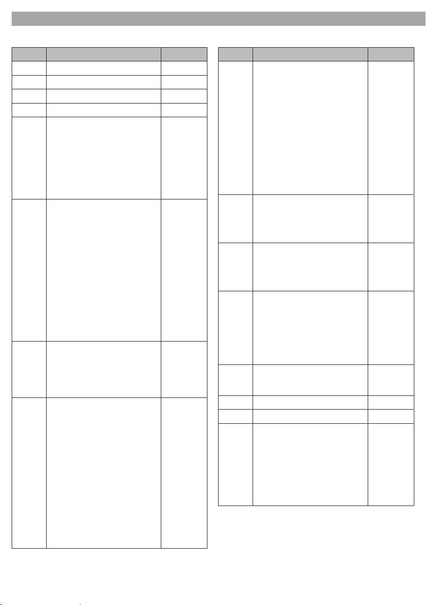
3.6 DMX control (16 channels operation)
Channel Function in the 16 channel mode DMX value
1 Pan 000-255
2 Tilt 000-255
3 Pan / Tilt speed 000-255
4 Dimmer 000-255
5 Shutter / Shaking
Shutter closed (blackout)
Shutter open
Stroboscope Slow - Fast
Shaking effect Slow - Fast
Shaking effect gobo wheel 1 Slow
- Fast
Shutter Open
6 Colour 1
White
Green
Magenta
Light Blue
Yellow
Red
Blue
UV purple
Light Green
Pink
Constant change of colour
Fast - Slow
Slow - Fast (opposite direction)
7 Iris
Diameter: Lange - Small
Slow close - Fast open
Slow open - Fast close
Open / Close: Slow to Fast
8 Gobo Wheel 1
No Gobo
Gobo1
Gobo2
Gobo3
Gobo4
Gobo5
Gobo6
Gobo7
Gobo8
Gobo9
Constant change of gobo:
Fast - Slow
Slow - Fast
000-007
008-015
016-131
132-185
186-239
240-255
000-012
013-025
026-038
039-050
051-063
064-076
077-088
089-101
102-114
115-127
128-191
192-255
0-127
128-169
170-212
213-255
000-012
013-025
026-038
039-050
051-063
064-076
077-088
089-101
102-114
115-127
128-191
192-255
Channel Function in the 16 channel mode DMX value
9 Gobo Wheel 2
No Gobo
Gobo10
Gobo11
Gobo12
Gobo13
Gobo14
Gobo15
Gobo16
Constant chage of gobo:
Fast - Slow
Slow - Fast
10 Gobo wheel 2 Rotation
Rotation angle of gobo
Clockwise rotation Fast - Slow
Counter-clockwise rotation Slow-Fast
11 Prism
no effect
Prism effect 1
Prism effect 2
12 Prism Rotation
No Prism rotation
Clockwise rotation Fast - Slow
No Prism rotation
Counter-clockwise rotation Slow
- Fast
No Prism rotation
13 Focus
Near - Far 0-255
14 Pan - 16 Bit (fine adjustment) 000-255
15 Tilt - 16 Bit (fine adjustment) 000-255
16 Reset / Lamp On-Off
No effect
Lamp on
No effect
DMX reset
No effect
Lamp off
No effect
000-015
016-031
032-047
048-063
064-079
080-095
096-111
112-127
128-191
192-255
000-127
128-191
192-255
000-085
086-170
171-255
000-009
010-120
121-134
135-245
246-255
0-129
130-139
139-199
200-209
210-229
230-239
240-255
Page 25
V575SPOT
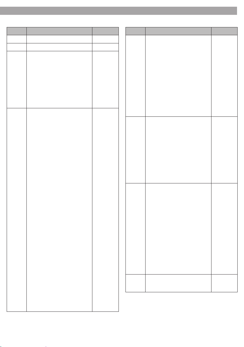
3.7 DMX control (8 channels operation)
Channel Function in the 8 channel mode DMX value
1 Pan 000-255
2 Tilt 000-255
3 Shutter
4 Gobo Wheel 1
Shutter closed (blackout)
Shutter open
Stroboscope Slow - Fast
Shaking
Shaking effect Slow - Fast
Shaking effect gobo wheel 1
Slow - Fast
Shutter Open
No Gobo
Gobo1
Gobo2
Gobo3
Gobo4
Gobo5
Gobo6
Gobo7
Gobo8
Gobo9
Gobo10
Gobo11
Gobo12
Gobo13
Gobo14
Gobo15
Gobo16
Gobo10+ Gobo1
Gobo10+ Gobo3
Gobo10+ Gobo5
Gobo10+ Gobo7
Gobo10+ Gobo9
Gobo13+ Gobo1
Gobo13+ Gobo3
Gobo13+ Gobo5
Gobo13+ Gobo7
Gobo13+ Gobo9
Gobo15+ Gobo1
Gobo15+ Gobo3
Gobo15+ Gobo5
Gobo15+ Gobo7
Gobo15+ Gobo9
Constant change of gobo1 (1-9)
Fast - Slow
Slow - Fast (opposite direction)
Constant change of gobo2 (10-15)
Fast - Slow
Slow - Fast (opposite direction)
000-007
008-015
016-131
132-185
186-239
240-255
000-003
004-007
008-011
012-015
016-019
020-023
024-027
028-031
032-035
036-039
040-043
044-047
048-051
052-055
056-059
060-063
064-067
068-071
072-075
076-079
080-083
084-087
088-091
092-095
096-099
100-103
104-107
108-111
112-115
116-119
120-123
124-127
128-159
160-187
188-219
220-255
9
Channel Function in the 8 channel mode DMX value
5 Colour
White
Green
Magenta
Light Blue
Yellow
Red
Blue
UV purple
Light Green
Pink
Constant change of colour
Fast - Slow
Slow - Fast (opposite direction)
6 Gobo wheel Rotation
Rotation angle of gobo
Clockwise rotation
Fast - Slow
Counter-clockwise rotation Slow
- Fast
Iris
Diameter: Lange - Small
Slow close - Fast open
Slow open - Fast close
Open / Close: Slow to Fast
7 Prism
no effect
Prism
Prism effect 1
Clockwise rotation
Fast - Slow
Counter-clockwise rotation Slow
- Fast
Prism effect 2
Clockwise rotation
Fast - Slow
Counter-clockwise rotation Slow
- Fast
Dimmer
8 Focus
Near - Far 0-255
000-012
013-025
026-038
039-050
051-063
064-076
077-088
089-101
102-114
115-127
128-191
192-255
000-063
064-095
096-127
128-191
192-212
213-234
235-255
000-015
016-031
032-055
056-079
080-103
104-127
128-255
Page 26
10
V575SPOT
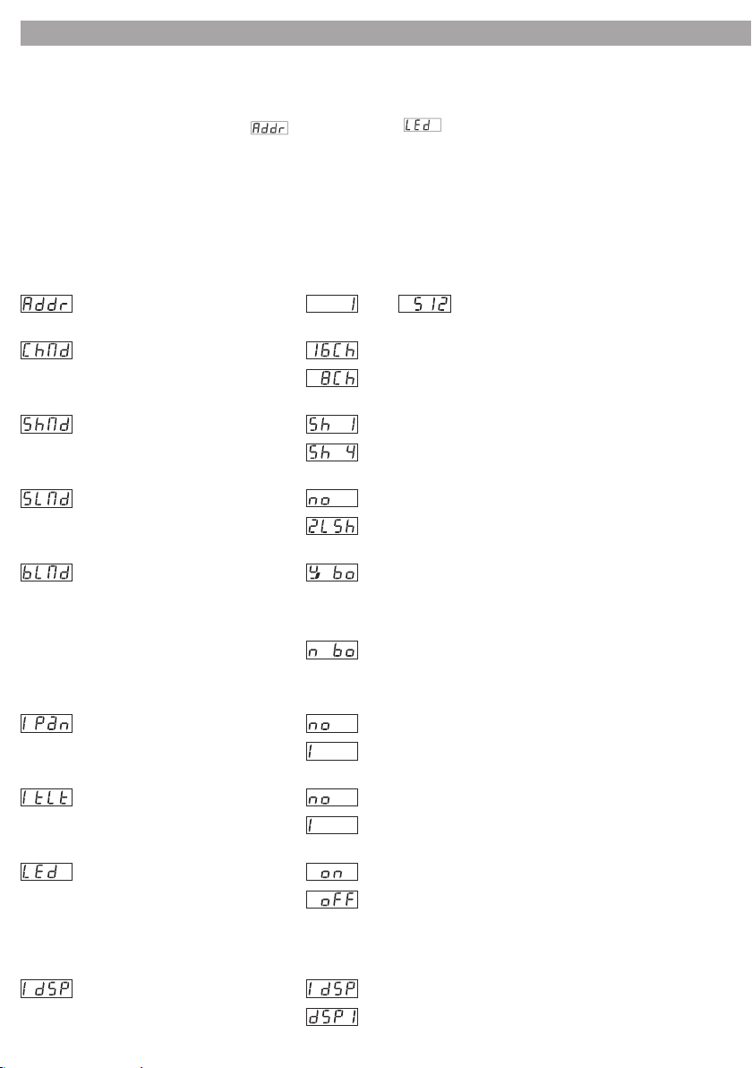
3.8 Changing the operating parameters
The parameters described below can be changed by calling the menu:
1. Press the button MENU (11) so many times until the corresponding menu item is shown on the display.
2. For the first eight menu items ( start address to display off), confirm the selection with the
button ENTER (13). Then make the adjustment with the button DOWN or UP (12) and memorize it with
the button ENTER within 8 seconds. The operation of the other menu items is described in detail. When
these menu items are selected, the display starts flashing.
3. To go to the next menu item, press the button MENU or select the desired menu item with the buttons
UP and DOWN (12).
4. If no further button is pressed for 8 seconds while a menu item is selected, the menu will disappear.
Adjustment of the start address:
16/8-channels DMX mode:
Show mode:
. . .
Slave mode:
. . .
Blackout mode:
Pan motion of the pan head: normal
Tilt motion of the pan head:
. . .
16 channels
8 channels
show 1
show 4
normal
2 light show
Blackout on (yes blackout). If no DMX control signal is
present at the jack DMX INPUT (6), the pan head will go to its
starting position and the shutter is closed. Operation via the
remote control is possible.
Blackout off (no blackout). If no DMX control signal is present,
the unit is controlled via the integrated microphone and, if
desired, via the remote control.
opposite panning
normal
opposite movement
LED Display on/off: display on
display off
After exiting the menu, the address or the operating mode will be displayed for approx. 30 s, then the display is switched
off. As soon as one of the buttons (11 – 13) is pressed, the display will be switched on again.
Display representation: normal
turned by 180° (for ceiling suspension)
Switch over the adjustment with the button ENTER. The display will flash for 8 seconds. Then the menu will disappear.
Page 27
V575SPOT
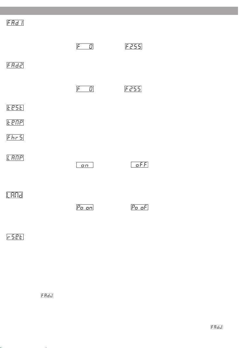
Focus adjustment for gobo wheel 1. After pressing the button ENTER, the head will go the vertical position
first; after each further actuation of the button ENTER, the four principal directions of the horizontal will be
selected. In the position which is closest to the intended direction of projection, the focus for the gobos of
gobo wheel 1 can be adjusted with the buttons DOWN and UP:
normal
. . .
Confirm the adjustment with the button ENTER. The value will be memorized and taken into account for the show programmes 1– 4.
Focus adjustment for gobo wheel 2. After pressing the button ENTER, the head will go the vertical position
first; after each further actuation of the button ENTER, the four principal directions of the horizontal will be
selected. In the position which is closest to the intended direction of projection, the focus for the gobos of
gobo wheel 2 can be adjusted with the buttons DOWN and UP:
normal
. . .
Confirm the adjustment with the button ENTER. The value will be memorized and taken into account for the show programmes 1– 4.
Self-test. After pressing the button ENTER, a test programme will be executed. To stop it, press the button
MENU. The next menu item will flash for 8 seconds. Then the menu will disappear.
Ambient temperature of the lamp. After pressing the button ENTER, the ambient temperature of the lamp (in
°C) will be indicated.
Working hour meter (fixture hours). After pressing the button ENTER, the display will show the working hours.
To return to the previous operating mode, press the button MENU. The next menu item will flash for 8 seconds.
Then the menu will disappear.
Lamp on/off. After pressing the button ENTER, the lamp can be switched on or off with the button UP or DOWN.
lamp on
Confirm the selection with the button ENTER.
Note: After switching off, the discharge lamp will not be able to ignite again immediately when it is still hot. Therefore,
there may be a delay of a few minutes before it is switched on again.
Lamp on/off on starting. After pressing the button ENTER, the lamp can be switched on or off with the button
UP or DOWN.
lamp on lamp off
Confirm the selection with the button ENTER.
Note: After switching off, the discharge lamp will not be able to ignite again immediately when it is still hot. Therefore,
there may be a delay of a few minutes before it is switched on again.
Reset. By pressing the button ENTER, the unit is reset: The pan head will shortly go to its starting position and
the shutter is closed. Then the unit will return to its previous operating mode.
lamp off
11
3.9 Presetting of corrective values (oset mode)
For fine adjustment of the pan head position, the two gobo wheels, and the colour wheel, readjustments
can be made in this mode.
1. Keep the button MENU pressed for at least 5 seconds. The first menu item will be displayed.
2. Press the button MENU so many times until the desired menu item is displayed.
3. Confirm the selection with the button ENTER.
Then make the adjustment with the button DOWN or UP and memorize it with the button ENTER within 8 sec. For
the menu point (focus adjustment) which is different than the others see the corresponding paragraph.
4. To go to the next menu item, press the button MENU or select the desired menu item with the buttons
UP and DOWN.
5. If no further button is pressed for 8 seconds while a menu item is selected, the menu will disappear.
Note: when calling this menu, the pan head will always go to the vertical position. If this direction of projection or the current focus is not suited for the readjustments intended, call the menu item (focus
adjustment) first and select another direction of projection or change the focus. The order shown here corresponds to the order of the menu items:
Page 28
12
V575SPOT
PAN Offset:
Fine adjustment for the horizontal pan head position
TILT Offset:
Fine adjustment for the vertical pan head position
Focus adjustment. After pressing the button ENTER, the head will go to the vertical position first; after each further
actuation of the button ENTER, the four principal directions in the horizontal will be selected. In the position which
is closest to the intended direction of projection, the focus can be adjusted with the buttons DOWN and UP:
By pressing the button MENU, the adjustment will be confirmed. The adjustment made here will merely help to adjust the
other parameters in this menu; it is insignificant for operation.
Gobo wheel 1offset
Fine adjustment for the gobo position of gobo wheel 1
Gobo wheel 2offset
Fine adjustment for the gobo position of gobo wheel 2
Colour wheel offset
Fine adjustment for the filter position of the colour wheel
. . .
. . .
. . .
. . .
. . .
. . .
3.10 Remote control EC800 (optional)
The remote control EC800 available as an accessory allows to control different functions:
1. Connect the remote control to the jack REMOTE CONTROL (4).
2. The DMX input (6) must not be connected; the yellow LED MASTER (15) must light up.
3. Via the DMX output (5), it is possible to connect further V575SPOT units in order to control them with the
remote control in sync with the master unit.
4. With the button STAND BY, the function blackout can be switched on and off. With the function switched on,
the led next to the button will light up. The pan head will go to its starting position and the shutter is closed.
5. With the button MODE (18), select the operating mode:
a) Mode SOUND 1 (LED next to the button does not light up).
By keeping the button FUNCTION (19) pressed, one of the three stroboscopic effects can be activated:
- strobe effect with varying colours and patterns;
- strobe effect with white light; identical effect for the slave units;
- strobe effect with white light; opposite effect for the slave units.
b) Mode SOUND 2 (LED flashing slowly).
By pressing the button FUNCTION (19), one of the four show operating modes can be activated. When
pressing the button FUNCTION once again, the next show operating mode respectively will be activated.
c) Mode SLOW/SOUND (LED lights continuously).
In this operating mode, only the movement of the light beam is music-controlled. The colours and pattern
are changed by the button FUNCTION. When pressing the button FUNCTION shortly, the next colour will be
selected; when pressing it longer, the next pattern will be selected.
d) Mode POSITION (LED flashing rapidly).
First the horizontal position of the head is defined by keeping the button FUNCTION pressed. Then the
vertical position of the head it defined by keeping the button FUNCTION pressed. Finally the value for the
dimmer or a prism effect is adjusted by keeping the button FUNCTION pressed. The positions and dimmer
values are defined for the master first, then the adjustments for the slave units will follow. The range of the
pan head during the modes SOUND 1 and SOUND 3 depends on the operating mode Show 1, Show 2, Show
3, or Show 4 selected in the menu or in the mode SOUND 2 via the remote control and shown on the display.
Page 29

V575SPOT
13
- 4 - MAINTENANCE
4.1 Cleaning the unit and maintenance
• Make sure the area below the installation place is free from unwanted persons during set-up.
• Switch off the unit, unplug the main cable and wait until the unit has cooled down.
• All screws used for installing the device and any of its parts should be tightly fastened and should not be corroded.
• Housings, fixations and installation spots (ceiling, trusses, suspensions) should be totally free from any deformation.
• When the lens is visibly damaged due to cracks or deep scratches, it must be replaced.
• The main cables must be in impeccable condition and should be replaced immediately even when a
small problem is detected.
• In order to protect the device from overheating the cooling fans (if any), and ventilation openings should
be cleaned monthly.
• The interior of the device should be cleaned annually using a vacuum cleaner or air-jet.
• It is recommended to clean the plastic panel of the unit at regular intervals, from impurities caused by
dust, smoke, or other particles to ensure that the light is radiated at maximum brightness. For cleaning,
disconnect the main plug from the socket. Use a soft, clean cloth moistened with a mild detergent. Then
carefully wipe the plastic pane dry. For cleaning other housing parts use only a soft, clean cloth. Never
use a liquid, it might penetrate the unit and cause damage to it.
Warning: we strongly recommend internal cleaning to be carried out by qualified personnel!
Gobos
1 2 3 4 5 6 7 8 9
Fig. 5
10 11 12 13 14 15 16
4.2 Replacement of the Gobos
The rotating gobos on the second gobo wheel can be replaced and e. g. be exchanged for individual gobos.
1. Disconnect the main plug from the socket and let the unit cool down for 15 minutes.
2. Release the screws (16) and remove the upper part of the housing of the pan head (1).
3. Turn the gobo wheel as indicated in fig. 6 in such a way that the gobo to be replaced is on top.
4. Remove the retaining ring (28) on the gobo by means of a suitable tool and remove the gobo.
Never release the screws on the gobo support; they keep the ball bearing together!
5. Insert the new gobo into the gobo support and fasten it with the retaining ring. If the gobo has a side
which is darker or more matt, this side must be directed towards the lamp.
6. Put the gobo support back into the gobo wheel so that it is clamped under the retaining ring (28).
7. Replace the housing of the pan head and retighten the screws.
28
Fig. 6
Page 30

Page 31
"
CERTIFICATO DI GARANZIA
GUARANTEE CERTIFICATE
Place Stamp Here
Arancare
Spett.le
Music&Lights s.r.l.
Via Appia Km 136.200
04020 Itri (LT) Italy
"
The guarantee covers the unit
in compliance with existing
regulations. You can nd the
full version of the “General
Il prodotto è coperto da garanzia
in base alle vigenti normative.
Sul sito www.musiclights.it è
possibile consultare il testo
Guarantee Conditions” on our
web site www.musiclights.it.
integrale delle “Condizioni
Generali di Garanzia”.
Abstract
General Guarantee Conditions
Estratto dalle
Condizioni Generali di Garanzia
piece of equipment soon after you
• Please remember to register the
procedere alla registrazione del
• Si prega, dopo l’acquisto, di
purchase it, logging on
www.musiclights.it. The product
prodotto sul sito www.musiclights.it.
In alternativa il prodotto può essere
can be also registered filling in
and sending the form available on
your guarantee certificate.
• Defects caused by inexperience
registrato compilando e inviando il
modulo riportato sul retro.
imperizia e da uso non appropriato
• Sono esclusi i guasti causati da
and incorrect handling of the
equipment are excluded.
effective if the equipment has
been tampered.
• The guarantee will no longer be
• The guarantee makes no provision
dell’apparecchio.
qualora l’apparecchio sia stato
manomesso.
• La garanzia non ha più alcun eetto
sostituzione dell’apparecchio.
• La garanzia non prevede la
for the replacement of the
equipment.
esterne, le lampade, le manopole, gli
• Sono escluse dalla garanzia le parti
switches and removable parts are
• External parts, lamps, handles,
interruttori e le parti asportabili.
• Le spese di trasporto e i rischi
not included in the guarantee.
conseguenti sono a carico del
• Transport costs and subsequent
possessore dell’apparecchio.
risks are responsibility of the
owner of the equipment.
the guarantee is endorsed solely
• For all purposes, the validity of
garanzia è avallata unicamente
dalla presentazione del certicato di
garanzia.
• A tutti gli eetti la validità della
on presentation of the guarantee
certificate.
Page 32
FORM TO BE FILLED IN AND MAILED / CEDOLA DA COMPILARE E SPEDIRE FORM TO BE FILLED IN AND KEPT / CEDOLA DA COMPILARE E CONSERVARE
"
Purchased by / Acquistato da
Purchasing date
Data acquisto
del Rivenditore
PROV.ZIP CODE / C.A.P.
CITY / CITTA’
ADDRESS / VIA N.
NAME / NOME
Dealer’s stamp
and signature
Timbro e rma
SURNAME / COGNOME
SERIAL N° / SERIE N°
MODEL / MODELLO
Purchased by / Acquistato da
Purchasing date
Data acquisto
del Rivenditore
PROV.ZIP CODE / C.A.P.
CITY / CITTA’
ADDRESS / VIA N.
NAME / NOME
Dealer’s stamp
and signature
Timbro e rma
SURNAME / COGNOME
SERIAL N° / SERIE N°
MODEL / MODELLO
Page 33

Page 34

Page 35

Page 36

©2009 Music & Lights SrlPROLIGHTS è un brand di proprietà della Music & Lights Srl. PROLIGHTS is a brand of Music & Lights Srl company.
Music & Lights Srl entertainment technologies
Via Appia Km 136,200 - 04020 Itri (LT) ITALY
tel. +39 0771 72190 fax +39 0771 721955
www.musiclights.it [email protected]
ISO 9001:2000
Certified Com pany
 Loading...