


BEAMROLL8Q
MULTI-BEAM PROJECTOR
MANUALE UTENTE
USER MANUAL
IT - EN

Music & Lights S.r.l. si riserva ogni diritto di elaborazione in qualsiasi forma delle presenti istruzioni per l’uso.
Al ne di migliorare la qualità dei prodotti, la Music&Lights S.r.l. si riserva la facoltà di modicare, in
qualunque momento e senza preavviso, le speciche menzionate nel presente manuale di istruzioni.
Tutte le revisioni e gli aggiornamenti sono disponibili nella sezione 'Manuali' sul sito www.musiclights.it
La riproduzione - anche parziale - per propri scopi commerciali è vietata.
REV.003-09/14

BEAMROLL8Q
3
INDICE
Sicurezza
Avvertenze generali
Attenzioni e precauzioni per l’installazione
Informazioni generali
1 Introduzione
1. 1 Descrizione
1. 2 Speciche tecniche
1. 3 Elementi di comando e di collegamento
2 Installazione
2. 1 Montaggio
3 Funzioni e impostazioni
3. 1 Funzionamento
3. 2 Impostazione base
3. 3 Struttura menu
3. 4 Modalità automatica
3. 5 Modalità musicale
3. 6 Modalità Master/Slave
3. 7 Collegamento
3. 8 Congurazioni canali DMX
3. 9 Modalità DMX
3. 10 Collegamenti della linea DMX
3. 11 Costruzione del terminatore DMX
3. 12 Canali DMX
3. 13 Impostazioni del proiettore
3. 14 Informazioni sul dispositivo
3. 15 Telecomando EC800 (opzionale)
4
4
5
6
6
7
8
9
9
10
11
11
11
11
11
12
13
13
14
18
18
19
Contenuto dell'imballo:
4 Manutenzione
4. 1 Manutenzione e pulizia del sistema ottico
4. 2 Sostituzione fusibile
4. 3 Risoluzione dei problemi
Certificato di garanzia
• BEAMROLL8Q
• Cavo di alimentazione
• Manuale utente
20
20
20

4
ATTENZIONE! Prima di effettuare qualsiasi operazione con l’unità, leggere con attenzione
questo manuale e conservarlo accuratamente per riferimenti futuri. Contiene informazioni
importanti riguardo l’installazione, l’uso e la manutenzione dell’unità.
BEAMROLL8Q
SICUREZZA
Avvertenze generali
• I prodotti a cui questo manuale si riferisce sono conformi alle Direttive della Comunità Europea e pertanto recano la sigla .
• Il dispositivo funziona con pericolosa tensione di rete 230V~. Non intervenire mai al suo interno al di
fuori delle operazioni descritte nel presente manuale; esiste il pericolo di una scarica elettrica.
• È obbligatorio eettuare il collegamento ad un impianto di alimentazione dotato di un’eciente messa
a terra (apparecchio di Classe I secondo norma EN 60598-1). Si raccomanda, inoltre, di proteggere le
linee di alimentazione delle unità dai contatti indiretti e/o cortocircuiti verso massa tramite l’uso di
interruttori dierenziali opportunamente dimensionati.
• Le operazioni di collegamento alla rete di distribuzione dell’energia elettrica devono essere eettuate
da un installatore elettrico qualicato. Vericare che frequenza e tensione della rete corrispondono alla
frequenza ed alla tensione per cui l’unità è predisposta, indicate sulla targhetta dei dati elettrici.
• L’unità non per uso domestico, solo per uso professionale.
• Evitare di utilizzare l’unità:
- in luoghi soggetti a vibrazioni, o a possibili urti;
- in luoghi a temperatura superiore ai 40°C;
- in luoghi soggetti ad eccessiva umidità.
• Evitare che nell’unità penetrino liquidi inammabili, acqua o oggetti metallici.
• Non smontare e non apportare modiche all’unità.
• Tutti gli interventi devono essere sempre e solo eettuati da personale tecnico qualicato. Rivolgersi al
più vicino centro di assistenza tecnica autorizzato.
• Se si desidera eliminare il dispositivo denitivamente, consegnarlo
per lo smaltimento ad un’istituzione locale per il riciclaggio.
Attenzioni e precauzioni per l’installazione
• Il dispositivo è destinato a solo uso interno, non è idoneo ad uso esterno.
• Se il dispositivo dovesse trovarsi ad operare in condizioni dierenti da quelle descritte nel presente
manuale, potrebbero vericarsi dei danni; in tal caso la garanzia verrebbe a decadere. Inoltre, ogni altra
operazione potrebbe provocare cortocircuiti, incendi, scosse elettriche, rotture etc.
• Prima di iniziare qualsiasi operazione di manutenzione o pulizia sull’unità togliere la tensione dalla rete
di alimentazione.
• È assolutamente necessario proteggere l’unità per mezzo di una fune di sicurezza. Nell’eseguire qualsiasi intervento attenersi scrupolosamente a tutte le normative (in materia di sicurezza) vigenti nel
paese di utilizzo.
• Installare l’unità in un luogo ben ventilato.
• Mantenere i materiali inammabili ad una distanza di sicurezza dall’unità.
• La temperatura massima raggiungibile sulla supercie esterna dell’unità, in condizioni di regime termi-
co, è di 85°C. Non toccare il prodotto quando è in funzione perché potrebbe essere molto caldo e dopo
lo spegnimento, attendere 15 minuti per il rareddamento.
• I ltri, le lenti o gli schermi ultravioletti se danneggiati possono limitare la loro ecienza.
• I LED devono essere sostituiti se danneggiati o termicamente deformati.
• Non guardare direttamente il fascio luminoso. Tenete presente che i veloci cambi di luce possono pro-
vocare attacchi d’epilessia presso persone fotosensibili o epilettiche.
• Non collegare il proiettore a un dimmer pack.

BEAMROLL8Q
INFORMAZIONI GENERALI
Spedizioni e reclami
Le merci sono vendute “franco nostra sede” e viaggiano sempre a rischio e pericolo del distributore/cliente. Eventuali avarie e danni dovranno essere contestati al vettore. Ogni reclamo per imballi manomessi
dovrà essere inoltrato entro 8 giorni dal ricevimento della merce.
Garanzie e resi
Il prodotto è coperto da garanzia in base alle vigenti normative. Sul sito www.musiclights.it è possibile
consultare il testo integrale delle “Condizioni Generali di Garanzia”. Si prega, dopo l’acquisto, di procedere
alla registrazione del prodotto sul sito www.musiclights.it. In alternativa il prodotto può essere registrato
compilando e inviando il modulo riportato alla ne del manuale. A tutti gli eetti la validità della garanzia
è avallata unicamente dalla presentazione del certicato di garanzia. Music & Lights constata tramite verica sui resi la difettosità dichiarata, correlata all’appropriato utilizzo, e l’eettiva validità della garanzia;
provvede quindi alla riparazione dei prodotti, declinando tuttavia ogni obbligo di risarcimento per danni
diretti o indiretti eventualmente derivanti dalla difettosità.
5

6
BEAMROLL8Q
- 1 - INTRODUZIONE
1.1 DESCRIZIONE
BEAMROLL8Q è una Beam Bar doppia con tilt motorizzato, composta da due le di LED ciascuna con 4
fasci controllabili singolarmente.
BEAMROLL8Q sprigiona 8 fasci di luce a lunga gittata grazie alla potente sorgente 8 LEDx 8W RGBW/FullColor e l’ottica da 4° per ogni lente d’emissione, risultando un proiettore versatile sia per applicazioni in
club che anche per concerti ed applicazioni in tour come eetto.BEAMROLL8Q ore modalità di controllo
avanzato sia in DMX con controllo pixel2pixel, ma anche modalità semplicate come pixel-macro preprogrammate, auto-show e sound-show che rendono l’utilizzo accessibile a tutti.
1.2 SPECIFICHE TECNICHE
Sorgente luminosa e ottica
• 8x8W RGBW/FC LED ad alta resa luminosa
• Angolo di proiezione: 4°
• Durata media diodi LED: >50.000 ore
Funzionamento ed elettronica
• Asse tilt motorizzato con rotazione a 145°
• Pannello di controllo tramite display LED (4 caratteri)
• Diverse congurazioni DMX disponibili (1, 6, 12, 36 canali) per controllo professionale o semplicato
- 1 canale: Show
- 6 canali: Tilt 1, Tilt 2, Master Dimmer, Strobe, Chase, Chase Speed
- 12 canali: Tilt 1, Tilt 2, Master Dimmer, Strobe, Color LED 1-8
- 36 canali: Tilt 1, Tilt 2, Master Dimmer, Strobe, RGBW 1-8
• Modalità Automatica: programmi automatici preimpostati con regolazione velocità
• Modalità Master/Slave: per il controllo di più unità collegate in catena
• Modalità Sound: attivazione musicale tramite microfono interno, controllo sensibilità
• Passaggio lineare “stepless” dei valori sui canali DMX
• Frequenza dei diodi anti-icker (400Hz) per videoriprese
Corpo e alimentazione
• Corpo in alluminio, grado di protezione: IP33
• Rareddamento ad aria ltrata forzata con ventole silenziate
• Riposizionamento automatico degli eetti in seguito a spostamenti accidentali
• Sospensione e ssaggio: qualsiasi posizione per mezzo di supporti omega (inclusi) con sistema di ag-
gancio “quick lock”
• Alimentazione: AC100-240V 50/60Hz
• Cablaggio IN/OUT alimentazione e segnale attraverso connessioni XLR3p/PowerCon
• Assorbimento medio: 66,5W (output no a 16 proiettori)
• Peso: 5,5 kg
• Dimensioni (LxAxP): 395x234x138 mm

BEAMROLL8Q
1.3 ELEMENTI DI COMANDO E COLLEGAMENTI
7
4 8
2 3 5 7 9 10 11
1. BARRA LED
2. POWER IN ( PowerCON IN): per il collegamento
ad una presa di rete (100-240V~/50-60Hz)
tramite il cavo rete in dotazione.
3. POWER OUT output alimentazione per connessione di più unità in serie.
4. PORTAFUSIBILE sostituire un fusibile difettoso
solo con uno dello stesso tipo (250V/T3.15A)
5. SAFETY RING per l’aggancio al cavo di
sicurezza.
6. DMX OUT (XLR a 3 poli):
1= massa, 2 = DMX -, 3 = DMX +
7. DMX IN (XLR a 3 poli):
1 = massa, 2 = DMX -, 3 = DMX +
8. MICROFONO per il comando tramite musica
9. CONNETTORE per il collegamento del telecomando EC800
10. INDICATORE LED (DMX, Master, Slave, Sound)
11. PANNELLO DI CONTROLLO con display e 4
6
12
1
pulsanti per accesso e gestione delle diverse
funzioni
12. Telecomando EC800
13. Tasto STAND BY - la barra mobile si porta in
posizione di partenza e il raggio di luce viene
disattivato. Il LED vicino al tasto si accende
come controllo
14. Tasto FUNCTION - per le diverse funzioni a
seconda del modo di funzionamento scelto
con il tasto MODE
15. Tasto MODE - per cambiare fra:
- modalità Sound (LED O)
- modalità Show (LED acceso)
- velocità (LED lampeggiante)
NOTA - Per poter usare il telecomando, all’ingresso
DMX IN non deve essere presente alcune segnale.
13
14
15
Fig.1Pannello di controllo e telecomando

8
BEAMROLL8Q
- 2 - INSTALLAZIONE
2.1 MONTAGGIO
Il BEAMROLL8Q può essere collocato su un piano solido. Inoltre, grazie ai fori di ssaggio, l’unità può
essere montata anche a testa in giù, su una traversa (g.2). Per il ssaggio occorrono dei supporti robusti
per il montaggio. Assicurarsi che l’unità sia saldamente ssata al ne di evitare vibrazioni e scivolamenti
durante il funzionamento.
L’area di collocazione deve avere una stabilità suciente e supportare almeno 10 volte il peso dell’unità.
Inoltre assicurarsi di rispettare tutte le avvertenze in materia di sicurezza.
È assolutamente necessario assicurare il proiettore contro la caduta utilizzando un cavo di sicurezza: in
particolare collegare il cavo in un punto adatto in modo che la caduta del proiettore non possa superare
i 20 cm.
GANCIO
ALISCAFF
SUPPORTI
OMEGA
CAVO DI
SICUREZZA
Fig.2

BEAMROLL8Q
9
- 3 - FUNZIONI E IMPOSTAZIONI
3.1 FUNZIONAMENTO
Per accendere il BEAMROLL8Q, inserire la spina del cavo di alimentazione in una presa di rete (240V~
50Hz). L’unità può essere comandata da un unità DMX di comando luce oppure svolgere autonomamente
il suo programma. Per spegnere il BEAMROLL8Q, staccare la spina dalla presa di rete. Per maggiore comodità è consigliabile collegare l’unità con una presa comandata da un interruttore.
3.2 IMPOSTAZIONE BASE
Il proiettore BEAMROLL8Q dispone di un display LED e 4 pulsanti per accesso alle funzioni del pannello di
controllo (g.3).
MENU UP DOWN ENTER
Per scorrere il menu
principale o tornare ad
una opzione del menu
precedente
Per scorrere attraverso le
diverse funzioni in ordine
discendente o aumentare il
valore della funzione stessa
Per scorrere attraverso le
diverse funzioni in ordine
ascendente o diminuire il
valore della funzione stessa
Per entrare nel menu selezionato o
confermare il valore attuale della
funzione o l'opzione all'interno di
un menu
Fig.3 - Funzione dei tasti

10
3.3 STRUTTURA MENU
BEAMROLL8Q
MENU (LEVEL 1) (LEVEL 2) REMARK
1 Addr
1 - 512 DMX ADDRESS
ð
2 ChMd
3 SlMd
4 ShMd
5 SoUn
6 bLMd
7 LEd
8 diSP
9 1tiL
10 2tiL
11 rEv
12 tESt AUTOTEST
1Ch CHANNEL MODE
ð
6Ch
12Ch
36Ch
MASt MASTER MODE
ð
SL1 SLAVE 1
SL 2 SLAVE 2
Sh 0 - Sh 12 RANDOM SHOW
ð
on SOUND MODE
ð
oFF
YES BLACKOUT MODE
ð
no
on LED DISPLAY
ð
oFF
diSP DISPLAY NORMAL
ð
dSiP DISPLAY INVERSION
YES TILT 1 INVERSION
ð
no
YES TILT 2 INVERSION
ð
no
YES REV
ð
no
13 tEMP TEMPERATURE TEST
14 FhrS FIXTURE USE TIME
15 vEr FIRMWARE VERSION
16 rSET RESET

BEAMROLL8Q
3.4 MODALITÀ AUTOMATICA
Se alla presa DMX non è presente alcun segnale di comando DMX, l’unità può svolgere il suo programma
Show autonomamente:
• Premere il tasto MENU no a quando sul display non appare ShMd, quindi premere il tasto ENTER.
• Premere il tasto UP/DOWN per scorrere al programma desiderato da 0 a 8 (Sh 0 - Sh 12). L’unità entrerà in
modalità automatica mandando in esecuzione il programma selezionato.
• Premere il tasto MENU per circa tre secondi per uscire dal menu d’impostazione.
NOTA - Nella modalità automatica l’unità è MASTER.
3.5 MODALITÀ MUSICALE
Nella modalità musicale l’unità può essere comandata tramite la musica. In presenza di segnale musicale,
con un determinato ritmo nei bassi e con volume suciente, tramite il microfono interno si comanda il
senso e la velocità di rotazione nonché il cambio di colore. Se il comando musica non dovesse funzionare
perfettamente, aumentare il volume o ridurre la distanza fra sorgente audio e l’unità oppure alternativamente aumentare la sensibilità del microfono.
• Premere il tasto MENU no a quando sul display non appare SoUn, quindi premere il tasto ENTER.
• Premere il tasto UP/DOWN per selezionare on oppure oFF a seconda che si voglia attivare o meno la
modalità musicale. Premere poi il tasto ENTER.
• Premere il tasto MENU per circa tre secondi per uscire dal menu d’impostazione.
3.6 MODALITÀ MASTER/SLAVE
Questa modalità consente di collegare in linea più unità BEAMROLL8Q senza un controller. La prima unità
sarà impostata come master e le altre funzioneranno come slave con lo stesso eetto.
• Premere il tasto MENU no a quando sul display non appare SLMd, quindi premere il tasto ENTER.
• Premere il tasto UP/DOWN per selezionare le diverse modalità di funzionamento: MASt (Master), SL 1
(Slave 1) oppure SL 2 (Slave 2), quindi premere il tasto ENTER.
• Sull’unità master selezionare il programma desiderato come indicato al paragrafo 3.4.
• Servirsi dei connettori DMX e di un cavo XLR per formare una catena di unità. In certe condizioni e lun-
ghezze si consiglia di eettuare una terminazione come mostrato a pagina 13.
• Premere il tasto MENU per circa tre secondi per uscire dal menu d’impostazione.
11
3.7 COLLEGAMENTO
Si possono collegare più unità anché tutte le unità secondarie abbiano lo stesso eetto luce dell’unità
principale (Master).
1. Collegare l’uscita DMX OUT dell’unità principale con l’ingresso DMX IN della prima unità secondaria
servendosi di un cavo XLR a 3 poli.
2. Collegare l’uscita DMX OUT della prima unità secondaria con l’ingresso DMX IN della seconda unità
secondaria ecc.
3.8 CONFIGURAZIONI CANALI DMX
Il BEAMROLL8Q dispone di 4 congurazioni dei canali DMX a cui si può accedere dal pannello di controllo.
• Premere il tasto MENU no a quando sul display non appare ChMd, quindi premere il tasto ENTER.
• Attraverso il tasto UP/DOWN selezionare la congurazione dei canali DMX che si desidera (1CH - 6CH
- 12CH - 36CH)
Le tabelle a pagina 14 indicano le modalità di funzionamento e i relativi valori DMX. Come interfaccia
DMX, l’unità possiede dei contatti XLR a 3 poli.

12
BEAMROLL8Q
3.9 MODALITÀ DMX
• Per poter entrare nella modalità DMX, premere il tasto MENU no a quando sul display non appare Addr,
quindi premere il tasto ENTER.
• Premere il tasto UP/DOWN e selezionare la modalità DMX .
• Dal menu iniziale, per impostare il valore desiderato, entrare nella modalità Addr e selezionare il valore
desiderato 001-512 ; tenere premuto per lo scorrimento veloce.
• Al termine dell’impostazione premere il tasto ENTER per salvare l’impostazione.
• Premere il tasto MENU per circa tre secondi per uscire dal menu d’impostazione.
Per poter comandare il BEAMROLL8Q con un’unità di comando luce, occorre impostare l’indirizzo di start
DMX per il primo canale DMX. Se, per esempio, sull’unità di comando è previsto l’indirizzo 33 per comandare la funzione del primo canale DMX, si deve impostare sul BEAMROLL8Q l’indirizzo di start 33. Le altre
funzioni del pannello saranno assegnate automaticamente agli indirizzi successivi. Segue un esempio con
indirizzo 33 di start e una congurazione a 12 canali DMX:
Numero
canali DMX
Indirizzo di
start (esempio)
Indirizzo DMX
occupati
Prossimo indirizzo di start
possibile per unità n°1
Prossimo indirizzo di start
possibile per unità n°2
Prossimo indirizzo di start
possibile per unità n°3
12 33 33-44 45 57 69
DMX Address: 33 DMX Address: 69DMX Address: 45 DMX Address: 57
DMX512 Controller
Fig.4 - Esempio di congurazione a 12 canali DMX
. . . . . . . . . . . .

BEAMROLL8Q
13
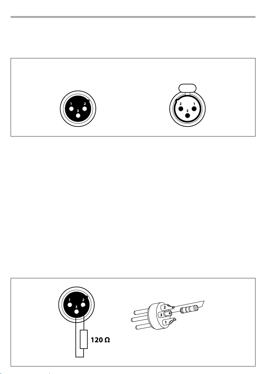
3.10 COLLEGAMENTI DELLA LINEA DMX
La connessione DMX è realizzata con connettori standard XLR. Utilizzare cavi schermati, 2 poli ritorti, con
impedenza 120Ω e bassa capacità.
Per il collegamento fare riferimento allo schema di connessione riportato di seguito:
DMX - INPUT
Spina XLR
Pin1 : Massa - Schermo
Pin2 : - Negativo
Pin3 : + Positivo
DMX - OUTPUT
Presa XLR
Fig.5
ATTENZIONE
La parte schermata del cavo (calza) non deve mai essere collegata alla terra dell’impianto; ciò comporterebbe malfunzionamenti delle unità e dei controller.
Per passaggi lunghi può essere necessario l’inserimento di un amplicatore DMX.
In tal caso, è sconsigliato utilizzare nei collegamenti cavo bilanciato microfonico poiché non è in grado di
trasmettere in modo adabile i dati di controllo DMX.
• Collegare l’uscita DMX del controller con l’ingresso DMX della prima unità;
• Collegare, quindi, l’uscita DMX con l’ingresso DMX della successiva unità; l’uscita di quest’ultima con
l’ingresso di quella successiva e via dicendo nchè tutte le unità sono collegate formando una catena.
• Per installazioni in cui il cavo di segnale deve percorrere lunghe distanze è consigliato inserire sull’ulti-
ma unità una terminazione DMX.
3.11 COSTRUZIONE DEL TERMINATORE DMX
La terminazione evita la probabilità che il segnale DMX 512, una volta raggiunta la ne della linea stessa
venga riesso indietro lungo il cavo, provocando, in certe condizioni e lunghezze, la sua sovrapposizione
al segnale originale e la sua cancellazione.
La terminazione deve essere eettuata, sull’ultima unità della catena, con connettori XLR a 3 pin, saldando
una resistenza di 120Ω (minimo 1/4W) tra i terminali 2 e 3, così come indicato in gura.
Esempio:
connettore XLR a 3 pin
Fig.6

14
3.12 CANALI DMX
1 CANALE
MODE
1 Ch
SHOW
Blackout
Show 1
Show 2
Show 3
Show 4
Show 5
1
Show 6
Show 7
Show 8
Show 9
Show 10
Show 11
Show 12
Random show
5
1
BEAMROLL8Q
FUNCTION DMX
Value
000 - 007
008 - 027
028 - 047
048 - 067
068 - 087
088 - 107
108 - 127
128 - 147
148 - 167
168 - 187
188 - 207
208 - 227
228 - 247
248 - 255
6 7 8
2 3 4
6 CANALI
MODE
FUNCTION DMX
6 Ch
TILT 1 MOVEMENT
1
60° - 150° 000 - 255
TILT 2 MOVEMENT
2
60° - 150° 000 - 255
MASTER DIMMER
3
0~100% 000 - 255
STROBE
No function
Slow to fast
Open
Slow open fast close
4
Open
Fast open slow close
Open
Random strobe
Open
CHASE
Blackout
Chase 1
Chase 2
Chase 3
Chase 4
Chase 5
Chase 6
Chase 7
5
Chase 8
Chase 9
Chase 10
Chase 11
Chase 12
Chase 13
Chase 14
Chase 15
Chase 16
Full on
CHASE SPEED
6
Slow to fast 000 - 255
Value
000 - 007
008 - 131
132 - 139
140 - 181
182 - 189
190 - 231
232 - 239
240 - 247
248 - 255
000 - 007
008 - 022
023 - 037
038 - 052
053 - 067
068 - 082
083 - 097
098 - 112
113 - 127
128 - 142
143 - 157
158 - 172
173 - 187
188 - 202
203 - 217
218 - 232
233 - 247
248 - 255

12 CANALI
MODE
FUNCTION DMX
12 Ch
TILT 1 MOVEMENT
1
60° - 150° 000 - 255
TILT 2 MOVEMENT
2
60° - 150° 000 - 255
MASTER DIMMER
3
0~100% 000 - 255
STROBE
No function
Slow to fast
Open
Slow open fast close
4
Open
Fast open slow close
Open
Random strobe
Open
COLOR LED 1
All o
Red
Green
Blue
White
Red + Green
Red + Blue
Red + White
5
Green + Blue
Green + White
Blue + White
Red + Green + Blue
Red + Green + White
Red + Blue + White
Green + Blue + White
Red + Green + Blue + White
Color change slow to fast
Color change by sound
COLOR LED 2
All o
Red
6
Green
Blue
White
Red + Green
BEAMROLL8Q
MODE
Value
000 - 007
008 - 131
132 - 139
140 - 181
182 - 189
190 - 231
232 - 239
240 - 247
248 - 255
000 - 007
008 - 015
016 - 023
024 - 031
032 - 039
040 - 047
048 - 055
056 - 063
064 - 071
072 - 079
080 - 087
088 - 095
096 - 103
104 - 111
112 - 119
120 - 127
128 - 247
248 - 255
000 - 007
008 - 015
016 - 023
024 - 031
032 - 039
040 - 047
12 Ch
Red + Blue
Red + White
Green + Blue
Green + White
Blue + White
Red + Green + Blue
6
Red + Green + White
Red + Blue + White
Green + Blue + White
Red + Green + Blue + White
Color change slow to fast
Color change by sound
COLOR LED 3
All o
Red
Green
Blue
White
Red + Green
Red + Blue
Red + White
7
Green + Blue
Green + White
Blue + White
Red + Green + Blue
Red + Green + White
Red + Blue + White
Green + Blue + White
Red + Green + Blue + White
Color change slow to fast
Color change by sound
COLOR LED 4
All o
Red
Green
Blue
White
8
Red + Green
Red + Blue
Red + White
Green + Blue
Green + White
Blue + White
Red + Green + Blue
15
FUNCTION DMX
Value
048 - 055
056 - 063
064 - 071
072 - 079
080 - 087
088 - 095
096 - 103
104 - 111
112 - 119
120 - 127
128 - 247
248 - 255
000 - 007
008 - 015
016 - 023
024 - 031
032 - 039
040 - 047
048 - 055
056 - 063
064 - 071
072 - 079
080 - 087
088 - 095
096 - 103
104 - 111
112 - 119
120 - 127
128 - 247
248 - 255
000 - 007
008 - 015
016 - 023
024 - 031
032 - 039
040 - 047
048 - 055
056 - 063
064 - 071
072 - 079
080 - 087
088 - 095

16
BEAMROLL8Q
MODE
12 Ch
Red + Green + White
Red + Blue + White
Green + Blue + White
8
Red + Green + Blue + White
Color change slow to fast
Color change by sound
COLOR LED 5
All o
Red
Green
Blue
White
Red + Green
Red + Blue
Red + White
9
Green + Blue
Green + White
Blue + White
Red + Green + Blue
Red + Green + White
Red + Blue + White
Green + Blue + White
Red + Green + Blue + White
Color change slow to fast
Color change by sound
COLOR LED 6
All o
Red
Green
Blue
White
Red + Green
Red + Blue
Red + White
10
Green + Blue
Green + White
Blue + White
Red + Green + Blue
Red + Green + White
Red + Blue + White
Green + Blue + White
Red + Green + Blue + White
Color change slow to fast
Color change by sound
FUNCTION DMX
Value
096 - 103
104 - 111
112 - 119
120 - 127
128 - 247
248 - 255
000 - 007
008 - 015
016 - 023
024 - 031
032 - 039
040 - 047
048 - 055
056 - 063
064 - 071
072 - 079
080 - 087
088 - 095
096 - 103
104 - 111
112 - 119
120 - 127
128 - 247
248 - 255
000 - 007
008 - 015
016 - 023
024 - 031
032 - 039
040 - 047
048 - 055
056 - 063
064 - 071
072 - 079
080 - 087
088 - 095
096 - 103
104 - 111
112 - 119
120 - 127
128 - 247
248 - 255
MODE
12 Ch
COLOR LED 7
All o
Red
Green
Blue
White
Red + Green
Red + Blue
Red + White
11
Green + Blue
Green + White
Blue + White
Red + Green + Blue
Red + Green + White
Red + Blue + White
Green + Blue + White
Red + Green + Blue + White
Color change slow to fast
Color change by sound
COLOR LED 8
All o
Red
Green
Blue
White
Red + Green
Red + Blue
Red + White
12
Green + Blue
Green + White
Blue + White
Red + Green + Blue
Red + Green + White
Red + Blue + White
Green + Blue + White
Red + Green + Blue + White
Color change slow to fast
Color change by sound
FUNCTION DMX
Value
000 - 007
008 - 015
016 - 023
024 - 031
032 - 039
040 - 047
048 - 055
056 - 063
064 - 071
072 - 079
080 - 087
088 - 095
096 - 103
104 - 111
112 - 119
120 - 127
128 - 247
248 - 255
000 - 007
008 - 015
016 - 023
024 - 031
032 - 039
040 - 047
048 - 055
056 - 063
064 - 071
072 - 079
080 - 087
088 - 095
096 - 103
104 - 111
112 - 119
120 - 127
128 - 247
248 - 255

BEAMROLL8Q
36 CANALI
MODE
36 Ch
TILT 1 MOVEMENT
1
60° - 150° 000 - 255
TILT 2 MOVEMENT
2
60° - 150° 000 - 255
MASTER DIMMER
3
0~100% 000 - 255
STROBE
No function
Slow to fast
Open
Slow open fast close
4
Open
Fast open slow close
Open
Random strobe
Open
5 RED LED 1 (0~100%) 000 - 255
6 GREEN LED 1 (0~100%) 000 - 255
7 BLUE LED 1 (0~100%) 000 - 255
8 WHITE LED 1 (0~100%) 000 - 255
9 RED LED 2 (0~100%) 000 - 255
10 GREEN LED 2 (0~100%) 000 - 255
11 BLUE LED 2 (0~100%) 000 - 255
12 WHITE LED 2 (0~100%) 000 - 255
13 RED LED 3 (0~100%) 000 - 255
14 GREEN LED 3 (0~100%) 000 - 255
15 BLUE LED 3 (0~100%) 000 - 255
FUNCTION DMX
000 - 007
008 - 131
132 - 139
140 - 181
182 - 189
190 - 231
232 - 239
240 - 247
248 - 255
Value
MODE
36 Ch
18 GREEN LED 4 (0~100%) 000 - 255
19 BLUE LED 4 (0~100%) 000 - 255
20 WHITE LED 4 (0~100%) 000 - 255
21 RED LED 5 (0~100%) 000 - 255
22 GREEN LED 5 (0~100%) 000 - 255
23 BLUE LED 5 (0~100%) 000 - 255
24 WHITE LED 5 (0~100%) 000 - 255
25 RED LED 6 (0~100%) 000 - 255
26 GREEN LED 6 (0~100%) 000 - 255
27 BLUE LED 6 (0~100%) 000 - 255
28 WHITE LED 6 (0~100%) 000 - 255
29 RED LED 7 (0~100%) 000 - 255
30 GREEN LED 7 (0~100%) 000 - 255
31 BLUE LED 7 (0~100%) 000 - 255
32 WHITE LED 7 (0~100%) 000 - 255
33 RED LED 8 (0~100%) 000 - 255
34 GREEN LED 8 (0~100%) 000 - 255
35 BLUE LED 8 (0~100%) 000 - 255
36 WHITE LED 8 (0~100%) 000 - 255
FUNCTION DMX
Value
17
16 WHITE LED 3 (0~100%) 000 - 255
17 RED LED 4 (0~100%) 000 - 255

18
3.13 IMPOSTAZIONI DEL PROIETTORE
Per il BEAMROLL8Q è possibile modicare i parametri relativi al dispositivo:
Impostazione funzioni proiettore
Dal menu iniziale, premere il tasto MENU, selezionare l’opzione proposta con il tasto UP/DOWN e premere il tasto ENTER per confermare l’impostazione.
• bLMd - Funzione Blackout. Selezionare YES, per entrare nella modalità blackout oppure selezionare no,
per disattivare la stessa funzione.
• LEd - Retroilluminazione display. on attiva la funzione (retroilluminazione display sempre attiva), oFF
disattiva la funzione (retroilluminazione display disattivata dopo circa un minuto).
• diSP - Inversione di visualizzazione display. diSP disattiva la funzione (display visualizzato in modalità
normale), dSiP attiva la funzione (display visualizzato in modalità invertita).
• 1tiL - Inclinazione in senso opposto della testa mobile 1. no disattiva la funzione (impostazione nor-
male), YES attiva la funzione (Tilt inverse).
• 2tiL - Inclinazione in senso opposto della testa mobile 2. no disattiva la funzione (impostazione nor-
male), YES attiva la funzione (Tilt inverse).
• rev - Modalità invertita di illuminazione dei LED. YES attiva la funzione (si accenderanno i LED su
entrambe le teste mobili in modo invertito), no disattiva la funzione (si accenderanno gli stessi LED
su entrambe le teste mobili).
• tEst - Verica dispositivo. Nella sezione tEst è possibile vericare il corretto funzionamento dell’unità.
Premere il tasto MENU per circa tre secondi per uscire dal menu d’impostazione.
Funzione Reset
Dal menu iniziale, premere il tasto MENU no a quando sul display non appare rSET, quindi premere il
tasto ENTER per il reset completo del proiettore.
BEAMROLL8Q
3.14 INFORMAZIONI SUL DISPOSITIVO
Informazioni proiettore
Dal menu iniziale, premere il tasto MENU, selezionare l’opzione proposta con il tasto UP/DOWN e premere il tasto ENTER per confermare l’impostazione.
• vEr - Attraverso la funzione vEr è possibile visualizzare sul display la versione del software installata
• tEMP - Attraverso la funzione tEMP è possibile visualizzare sul display la temperatura relativa al dispo-
sitivo.
• FhrS - Attraverso la funzione FhrS è possibile visualizzare sul display il tempo di funzionamento del
proiettore.
Premere il tasto MENU per circa tre secondi per uscire dal menu d’impostazione.

BEAMROLL8Q
3.15 TELECOMANDO EC800 (opzionale)
Con il telecomando EC800 (g.7) si possono controllare diverse funzioni come riportato nella tabella di
seguito.
BUTTON FUNCTION
BLACKOUT Blackout the unit
FUNCTION
MODE Random Show (LED OFF) Show (LED ON)
Fig.7
• Collegare il telecomando con la presa ONLY REMOTE CONTROL.
• L’ingresso DMX non deve essere collegato
• All’uscita DMX si possono collegare altri proiettori BEAMROLL8Q per movimenti telecomandati sincro-
nizzati con l’unità principale.
• Con il tasto BLACKOUT si possono attivare e disattivare i raggi luce. Se la funzione è attiva, il LED vicino
al tasto è acceso. La testa mobile ritorna nella posizione di partenza e il raggio viene disattivato.
• Con il tasto FUNCTION selezionare la modalità di funzionamento:
a) Funzione SOUND STROBE (il LED vicino al tasto è acceso)
Tenendo premuto il tasto FUNCTION si può attivare uno dei due eetti stroboscopici:
- Eetto stroboscopico dipendente dalla musica
- Eetto stroboscopico indipendente dalla musica, in sincronia con le unità secondarie
b) Funzione SHOW (il LED vicino al tasto è acceso)
- Con il tasto FUNCTION si può scegliere il programma Show desiderato (1-8)
• Con il tasto MODE si può scegliere tra RANDOM SHOW (il LED vicino al tasto è spento) e SHOW (il LED
vicino al tasto è acceso). Con la pressione prolungata del tasto FUNCTION è possibile regolare il valore
della funzione selezionata.
1. Sound Strobe (Full ON)
2. Auto Strobe (Full ON)
Select Show
Show 1 - 8
19

20
BEAMROLL8Q
- 4 - MANUTENZIONE
4.1 MANUTENZIONE E PULIZIA DEL SISTEMA OTTICO
• Durante gli interventi, assicurarsi che l’area sotto il luogo di installazione sia libera da personale non
qualicato.
• Spegnere l’unità, scollegare il cavo di alimentazione ed aspettare nché l’unità non si sia rareddata.
• Tutte le viti utilizzate per l’installazione dell’unità e le sue parti devono essere assicurate saldamente e
non devono essere corrose.
• Alloggiamenti, elementi di ssaggio e di installazione (sotto, truss, sospensioni) devono essere totalmente esenti da qualsiasi deformazione.
• I cavi di alimentazione devono essere in condizione impeccabile e devono essere sostituiti immediatamente nel momento in cui anche un piccolo problema viene rilevato.
• Si dovrebbe procedere, ad intervalli regolari, alla pulizia della parte frontale per asportare polvere,
fumo e altre particelle. Solo così, la luce può essere irradiata con la luminosità massima. Per la pulizia
usare un panno morbido, pulito e un detergente per vetri come si trovano in commercio. Quindi asciugare le parti delicatamente.
4.2 SOSTITUZIONE FUSIBILE
1. Assicurarsi di scollegare il cavo di alimentazione del proiettore prima di sostituire
un fusibile bruciato con uno dello stesso tipo.
2. Con un cacciavite, rimuovere il portafusibile dalla sua sede e il fusibile bruciato dal
suo supporto; sostituire il fusibile con uno identico per tipologia e valore (T3.15A
250V).
3. Inserire il portafusibile al suo posto e ricollegare l’alimentazione.
Fig.8
4.3 RISOLUZIONE DEI PROBLEMI
Anomalie Possibili cause Controlli e rimedi
• Mancanza di alimentazione di rete
• Dimmer impostato a 0
Il dispositivo non illumina
Bassa intensità di luce generale
Il dispositivo non è alimentato
• Tutti i colori impostati a 0
• LED difettoso/i
• Scheda LED difettosa
• Lenti sporche • Pulire il dispositivo regolarmente
• Mancanza di alimentazione di rete
• Cavo di alimentazione danneggiato
• Alimentatore interno difettoso
• Indirizzamento DMX errato
Il dispositivo non risponde al
DMX
Rivolgersi a un centro di assistenza tecnico autorizzato nel caso in cui il problema non sia riportato in
tabella.
• Cavo di segnale DMX difettoso
• Rimbalzo segnale DMX
• Vericare la presenza della tensione alimentazione
• Incrementare i valori del canale dimmer
• Incrementare i valori dei canali colori
• Sostituire scheda LED
• Sostituire scheda LED
• Vericare la presenza della tensione alimentazione
• Controllare il cavo di alimentazione
• Sostituire l'alimentatore interno
• Controllare il pannello di controllo e
l'indirizzamento delle unità
• Controllare il cavo di segnale DMX
• Installare una terminazione DMX come suggerito


All rights reserved by Music & Lights S.r.l. No part of this instruction manual may be
reproduced in any form or by any means for any commercial use.
In order to improve the quality of products, Music&Lights S.r.l. reserves the right to modify the
characteristics stated in this instruction manual at any time and without prior notice.
All revisions and updates are available in the ‘manuals’ section on site www.musiclights.it

BEAMROLL8Q
1
TABLE OF CONTENTS
Safety
General instructions
Warnings and installation precautions
General information
1 Introduction
1. 1 Description
1. 2 Technical specications
1. 3 Operating elements and connections
2 Installation
2. 1 Mounting
3 Functions and settings
3. 1 Operation
3. 2 Basic
3. 3 Menu structure
3. 4 Automatic mode
3. 5 Music mode
3. 6 Master/Slave mode
3. 7 Linking
3. 8 DMX conguration
3. 9 DMX mode
3. 10 Connection of the DMX line
3. 11 Construction of the DMX termination
3. 12 DMX control
3. 13 Fixture Settings
3. 14 Information
3. 15 Remote Control EC800 (optional)
2
2
3
4
4
5
6
7
7
8
9
9
9
9
9
9
11
11
12
16
16
16
Packing content
4 Maintenance
4. 1 Maintenance and cleaning the unit
4. 2 Fuse replacement
4. 3 Troubleshooting
Warranty
• BEAMROLL8Q
• Power cord
• User manual
18
18
18

2
WARNING! Before carrying out any operations with the unit, carefully read this instruction
manual and keep it with cure for future reference. It contains important information about
the installation, usage and maintenance of the unit.
BEAMROLL8Q
SAFETY
General instruction
• The products referred to in this manual conform to the European Community Directives and are therefore marked with .
• The unit is supplied with hazardous network voltage (230V~). Leave servicing to skilled personnel only.
Never make any modications on the unit not described in this instruction manual, otherwise you will
risk an electric shock.
• Connection must be made to a power supply system tted with ecient earthing (Class I appliance according to standard EN 60598-1). It is, moreover, recommended to protect the supply lines of the units
from indirect contact and/or shorting to earth by using appropriately sized residual current devices.
• The connection to the main network of electric distribution must be carried out by a qualied electrical
installer. Check that the main frequency and voltage correspond to those for which the unit is designed
as given on the electrical data label.
• This unit is not for home use, only professional applications.
• Never use the xture under the following conditions:
- in places subject to vibrations or bumps;
- in places with a temperature of over 40 °C;
- in places subject to excessive humidity.
• Make certain that no inammable liquids, water or metal objects enter the xture.
• Do not dismantle or modify the xture.
• All work must always be carried out by qualied technical personnel. Contact the nearest sales point for
an inspection or contact the manufacturer directly.
• If the unit is to be put out of operation denitively, take it to a local recycling
plant for a disposal which is not harmful to the environment.
Warnings and installation precautions
• The xture is for indoor use only and is not intended for outdoor use.
• If this device will be operated in any way dierent to the one described in this manual, it may suer
damage and the guarantee becomes void. Furthermore, any other operation may lead to dangers like
short circuit, burns, electric shock, etc.
• Before starting any maintenance work or cleaning the projector, cut o power from the main supply.
• Always additionally secure the projector with the safety rope. When carrying out any work, always com-
ply scrupulously with all the regulations (particularly regarding safety) currently in force in the country
in which the xture’s being used.
• Install the xture in a well ventilated place.
• Keep any inammable material at a safe distance from the xture.
• The maximum temperature that can be reached on the external surface of the tting, in a thermally
steady state, is 85°C. Do not touch this product when it is operating because it may be hot and after
switching o, do not remove any parts of the tting for at least 15 minutes.
• Shields, lenses or ultraviolet screens shall be changed if they have become damaged to such an extent
that their eectiveness is impaired.
• The lamp (LED) shall be changed if it has become damaged or thermally deformed.
• Never look directly at the light beam. Please note that fast changes in lighting, e. g. ashing light, may
trigger epileptic seizures in photosensitive persons or persons with epilepsy.
• Never connect the device to any dimmer pack.

BEAMROLL8Q
GENERAL INFORMATION
Shipments and claims
The goods are sold “ex works” and always travel at the risk and danger of the distributor. Eventual damage will have to be claimed to the freight forwarder. Any claim for broken packs will have to be forwarded
within 8 days from the reception of the goods.
Warranty and returns
The guarantee covers the xture in compliance with existing regulations. You can nd the full version of
the “General Guarantee Conditions” on our web site www.musiclights.it. Please remember to register the
piece of equipment soon after you purchase it, logging on www.musiclights.it. The product can be also
registered lling in and sending the form available on your guarantee certicate. For all purposes, the validity of the guarantee is endorsed solely on presentation of the guarantee certicate. Music & Lights will
verify the validity of the claim through examination of the defect in relation to proper use and the actual
validity of the guarantee. Music & Lights will eventually provide replacement or repair of the products declining, however, any obligation of compensation for direct or indirect damage resulting from faultiness.
3

4
BEAMROLL8Q
- 1 - INTRODUCTION
1.1 DESCRIPTION
BEAMROLL8Q is a Dual Beam Bar with motorized tilt, consisting of two rows of LEDs, each with 4 beams
individually controllable.
BEAMROLL8Q deliver 8 punchy beams, which perform long through projection thanks to the powerful
8x8W RGBW/FullColor LED source and 4° narrow optics on each pods, resulting in a versatile projector for
applications as eect in clubs and concerts. BEAMROLL8Q oers advanced control modes as DMX control
with pixel2pixel managment, but also simplied modes such as pre-programmed macro-pixel, auto showand-sound show which make use accessible to everyone.
1.2 TECHNICAL SPECIFICATIONS
Light source and optics
• 8x8W RGBW/FC LEDs high brightness
• Beam angle: 4°
• LEDs average life span:> 50,000 hours
Electronics and features
• Motorized tilt axis with rotation to 145°
• Control Panel with LED display (4 chars)
• Dierent DMX available congurations (1, 6, 12, 36 channels) for professional or simplied control
- 1 channel: Show
- 6 channels: Tilt 1, Tilt 2, Master Dimmer, Strobe, Chase, Chase Speed
- 12 channels: Tilt 1, Tilt 2, Master Dimmer, Strobe, Color LED 1-8
- 36 channels: Tilt 1, Tilt 2, Master Dimmer, Strobe, RGBW 1-8
• Auto mode: preset automatic programs with speed control
• Master / Slave: For the control of several units linked in a chain
• Sound Mode: Switch music via the internal microphone, sensitivity control
• Linear passage “stepless” DMX values
• Frequency diode anti-icker (400Hz) for video recordings
Structure and Power supply
• Aluminium housing, degree of protection: IP33
• Filtered forced air cooling fan with low noise
• Automatic repositioning after accidental movement
• Suspension and Mounting: any position through omega (included) with a system of “quick lock”
• Power supply: AC100-240V 50/60Hz
• Wiring IN / OUT signal and power connections through XLR3p/Powercon
• Average power consumption: 66,5W (output up to 16 projectors)
• Weight: 5,5 kg
• Dimensions (WxHxD): 395x234x138 mm

BEAMROLL8Q
1.3 OPERATING ELEMENTS AND CONNECTIONS
5
4 8
2 3 5 7 9 10 11
1. LED BAR
2. POWER IN (PowerCON IN): for connection to a
socket (100-240V~/50-60Hz) via the supplied
mains cable.
3. POWER OUT power output for connection of
multiple units in series
4. MAIN FUSE HOLDER (250V/T3.15A) replace a
burnt-out fuse by one of the same type only)
5. SAFETY RING to attach safety cable
6. DMX OUT ( 3-pole XLR):
1 = ground, 2 = DMX -, 3 = DMX +
7. DMX IN (3-pole XLR):
1 = ground, 2 = DMX -, 3 = DMX +
8. MICROPHONE for music control
9. CONNECTION Jack for the remote control
EC800
10. LED INDICATOR (DMX, Master, Slave, Sound)
6
12
1
11. CONTROL PANEL with display and 4 buttons
for access and management of dierent
functions
12. REMOTE CONTROL EC800
13. Button STAND BY - The movable head is
brought into the starting position and the
light beam is turned o. The LED next to the
button comes on as a control
14. Button FUNCTION for dierent functions
depending on the operating mode selected
with the MODE button
15. Button MODE:
- Mode Sound (LED o)
- Mode Show (LED on)
- Mode speed (LED blinking)
NOTE - For operation via the remote control, no
DMX signal must be present at the input DMX IN..
13
14
15
Fig.1Control Panel and Controller

6
BEAMROLL8Q
- 2 - INSTALLATION
2.1 MOUNTING
The BEAMROLL8Q may be set up on a solid and even surface. By means of the xing facilities of the baseplate, the unit can also be mounted upside down to a cross arm (g.2). For xing, stable mounting clips
are required. Always ensure that the unit is rmly xed to avoid vibration and slipping while operating.
The mounting place must be of sucient stability and be able to support a weight of 10 times of the unit’s
weight. When carrying out any installation, always comply scrupulously with all the regulations (particularly regarding safety) currently in force in the country in which the xture’s being used.
Always additionally secure the projector with the safety rope from falling down. For this purpose, fasten
the safety rope at a suitable position so that the maximum fall of the projector will be 20 cm.
CLAMP
ALISCAFF
OMEGA
SUPPORTS
SECURITY
CABLE
Fig.2

BEAMROLL8Q
7
- 3 - FUNCTIONS AND SETTINGS
3.1 OPERATION
Connect the supplied main cable to a socket (100-240 VAC-50/60 Hz). Then the unit is ready for operation
and can be operated via a DMX controller or it independently performs its show program in succession.
To switch o, disconnect the mains plug from the socket. For a more convenient operation it is recommended to connect the unit to a socket which can be switched on and o via a light switch.
3.2 BASIC
Access control panel functions using the four panel buttons located directly underneath the LED Display
(g.3).
MENU UP DOWN ENTER
Used to access the menu or
to return a previous menu
option
Navigates downwards through
the menu list and increases
the numeric value when in a
function
Navigates upwards through
the menu list and decreases
the numeric value when in
a function
Used to select and store the
current menu or conrm the
current function value or
option within a menu
Fig.3 - Functions of the buttons

8
3.3 MENU STRUCTURE
BEAMROLL8Q
MENU (LEVEL 1) (LEVEL 2) REMARK
1 Addr
1 - 512 DMX ADDRESS
ð
2 ChMd
3 SlMd
4 ShMd
5 SoUn
6 bLMd
7 LEd
8 diSP
9 1tiL
10 2tiL
11 rEv
12 tESt AUTOTEST
1Ch CHANNEL MODE
ð
6Ch
12Ch
36Ch
MASt MASTER MODE
ð
SL1 SLAVE 1
SL 2 SLAVE 2
Sh 0 - Sh 12 RANDOM SHOW
ð
on SOUND MODE
ð
oFF
YES BLACKOUT MODE
ð
no
on LED DISPLAY
ð
oFF
diSP DISPLAY NORMAL
ð
dSiP DISPLAY INVERSION
YES TILT 1 INVERSION
ð
no
YES TILT 2 INVERSION
ð
no
YES REV
ð
no
13 tEMP TEMPERATURE TEST
14 FhrS FIXTURE USE TIME
15 vEr FIRMWARE VERSION
16 rSET RESET

BEAMROLL8Q
3.4 AUTOMATIC MODE
If no DMX control signal is present at the DMX INPUT, the unit independently runs through its show programme provided that the blackout mode is switched o:
• Press the button MENU so many times until the display shows ShMd, then press the button ENTER.
• Press the button UP/DOWN to switch between the programs (Sh 0 - Sh 12). The unit will operate in auto-
matic mode.
• Hold and press the button MENU for three seconds to exit the menu mode.
NOTE - In automatic mode the unit will be set as Master.
3.5 MUSIC MODE
In music mode, via its integrated microphone, the unit can be controlled by music with a clear rhythm in
the bass range. If the music control should not work optimally, increase the volume or reduce the distance
between the sound source and the light eect unit.
• Press the button MENU so many times until the display shows SoUn, then press the button ENTER.
• Press the button UP/DOWN to select on or oFF to enable or disable the sound mode.
• Hold and press the button MENU for three seconds to exit the menu mode.
3.6 MASTER/SLAVE MODE
This mode will allow you to link up the units together without a controller. Choose a unit to function as the
Master. The unit must be the rst unit in line; other units will work as slave with the same eect.
• Press the button MENU so many times until the display shows SLMd and press the button ENTER.
• Press the button UP/DOWN to select the dierent modes of operation: MASt (Master), SL 1 (Slave 1) or
SL 2 (Slave 2), then press the button ENTER.
• Use standard DMX cables to daisy chain your units together via the DMX connector on the rear of the
units. For longer cable runs we suggest a terminator at the last xture (see page 11).
• Hold and press the button MENU for three seconds to exit the menu mode.
9
3.7 LINKING
Several units may be interconnected in order to control all further slave units to the same eect of the
master unit.
1. Connect the DMX OUT of the master unit via 3-pole XLR cable to the DMX IN of the rst slave unit.
2. Connect the DMX OUT of the rst slave unit to the DMX IN of the second slave unit, etc. until all units
are connected in a chain.
3.8 DMX CONFIGURATION
The BEAMROLL8Q is equipped with dierent DMX conguration.
• Press the button MENU so many times until shows ChMd, and press the button ENTER to conrm.
• Select the desired DMX conguration (1Ch - 6CH - 12CH - 36CH) through the button UP/ DOWN.
• Press the ENTER button to conrm.
• Press the MENU button to go back or wait some seconds for automatic exit from the menu.
The tables on page 12 indicate the operating mode and DMX value. The BEAMROLL8Q is equipped with
3-pole XLR connections.
3.9 DMX MODE
For operation via light control unit with DMX512 protocol, is sucient connect the controller to device.

10
BEAMROLL8Q
The projector has dierent congurations of DMX channels the values of which see tables on page 12.
• To set the DMX address, press the button MENU so many times until shows Addr, then press the button
ENTER to conrm.
• Press the button UP/DOWN to select the desider value (001 - 512), then press the button ENTER to con-
rm.
• Hold and press the button MENU for three seconds to exit the menu mode.
To able to operate the BEAMROLL8Q with a light controller, adjust the DMX start address for the rst a
DMX channel. If e. g. address 33 on the controller is provided for controlling the function of the rst DMX
channel, adjust the start address 33 on the BEAMROLL8Q. The other functions of the light eect panel are
then automatically assigned to the following addresses.
An example with the start address 33 is shown below:
Number of
DMX channels
Start address
(example)
DMX Address
occupied
Next possible start
address for unit No. 1
Next possible start
address for unit No. 2
12 33 33-44 45 57 69
DMX Address: 33 DMX Address: 69DMX Address: 45 DMX Address: 57
DMX512 Controller
Fig.4 - Example 12 DMX channels conguration
Next possible start
address for unit No. 3
. . . . . . . . . . . .
BEAMROLL8Q
11
3.10 CONNECTION OF THE DMX LINE
DMX connection employs standard XLR connectors. Use shielded pair-twisted cables with 120Ω impedance and low capacity.
The following diagram shows the connection mode:
DMX - INPUT
XLR plug
Pin1 : GND - Shield
Pin2 : - Negative
Pin3 : + Positive
DMX - OUTPUT
XLR socket
Fig.5
ATTENTION
The screened parts of the cable (sleeve) must never be connected to the system’s earth, as this would
cause faulty xture and controller operation.
Over long runs can be necessary to insert a DMX level matching amplier.
For those connections the use of balanced microphone cable is not recommended because it cannot
transmit control DMX data reliably.
• Connect the controller DMX input to the DMX output of the rst unit.
• Connect the DMX output to the DMX input of the following unit. Connect again the output to the input
of the following unit until all the units are connected in chain.
• When the signal cable has to run longer distance is recommended to insert a DMX termination on the
last unit.
3.11 CONSTRUCTION OF THE DMX TERMINATION
The termination avoids the risk of DMX 512 signals being reected back along the cable when they reaches the end of the line: under certain conditions and with certain cable lengths, this could cause them to
cancel the original signals.
The termination is prepared by soldering a 120Ω 1/4 W resistor between pins 2 and 3 of the 5-pin male XLR
connector, as shown in gure.
Example:
3 pin XLR connector
Fig.6

12
3.12 DMX CONTROL
1 CHANNEL
MODE
1 Ch
SHOW
Blackout
Show 1
Show 2
Show 3
Show 4
Show 5
1
Show 6
Show 7
Show 8
Show 9
Show 10
Show 11
Show 12
Random show
5
1
BEAMROLL8Q
FUNCTION DMX
Value
000 - 007
008 - 027
028 - 047
048 - 067
068 - 087
088 - 107
108 - 127
128 - 147
148 - 167
168 - 187
188 - 207
208 - 227
228 - 247
248 - 255
6 7 8
2 3 4
6 CHANNELS
MODE
FUNCTION DMX
6 Ch
TILT 1 MOVEMENT
1
60° - 150° 000 - 255
TILT 2 MOVEMENT
2
60° - 150° 000 - 255
MASTER DIMMER
3
0~100% 000 - 255
STROBE
No function
Slow to fast
Open
Slow open fast close
4
Open
Fast open slow close
Open
Random strobe
Open
CHASE
Blackout
Chase 1
Chase 2
Chase 3
Chase 4
Chase 5
Chase 6
Chase 7
5
Chase 8
Chase 9
Chase 10
Chase 11
Chase 12
Chase 13
Chase 14
Chase 15
Chase 16
Full on
CHASE SPEED
6
Slow to fast 000 - 255
Value
000 - 007
008 - 131
132 - 139
140 - 181
182 - 189
190 - 231
232 - 239
240 - 247
248 - 255
000 - 007
008 - 022
023 - 037
038 - 052
053 - 067
068 - 082
083 - 097
098 - 112
113 - 127
128 - 142
143 - 157
158 - 172
173 - 187
188 - 202
203 - 217
218 - 232
233 - 247
248 - 255

12 CHANNELS
MODE
FUNCTION DMX
12 Ch
TILT 1 MOVEMENT
1
60° - 150° 000 - 255
TILT 2 MOVEMENT
2
60° - 150° 000 - 255
MASTER DIMMER
3
0~100% 000 - 255
STROBE
No function
Slow to fast
Open
Slow open fast close
4
Open
Fast open slow close
Open
Random strobe
Open
COLOR LED 1
All o
Red
Green
Blue
White
Red + Green
Red + Blue
Red + White
5
Green + Blue
Green + White
Blue + White
Red + Green + Blue
Red + Green + White
Red + Blue + White
Green + Blue + White
Red + Green + Blue + White
Color change slow to fast
Color change by sound
COLOR LED 2
All o
Red
6
Green
Blue
White
Red + Green
BEAMROLL8Q
MODE
Value
000 - 007
008 - 131
132 - 139
140 - 181
182 - 189
190 - 231
232 - 239
240 - 247
248 - 255
000 - 007
008 - 015
016 - 023
024 - 031
032 - 039
040 - 047
048 - 055
056 - 063
064 - 071
072 - 079
080 - 087
088 - 095
096 - 103
104 - 111
112 - 119
120 - 127
128 - 247
248 - 255
000 - 007
008 - 015
016 - 023
024 - 031
032 - 039
040 - 047
12 Ch
Red + Blue
Red + White
Green + Blue
Green + White
Blue + White
Red + Green + Blue
6
Red + Green + White
Red + Blue + White
Green + Blue + White
Red + Green + Blue + White
Color change slow to fast
Color change by sound
COLOR LED 3
All o
Red
Green
Blue
White
Red + Green
Red + Blue
Red + White
7
Green + Blue
Green + White
Blue + White
Red + Green + Blue
Red + Green + White
Red + Blue + White
Green + Blue + White
Red + Green + Blue + White
Color change slow to fast
Color change by sound
COLOR LED 4
All o
Red
Green
Blue
White
8
Red + Green
Red + Blue
Red + White
Green + Blue
Green + White
Blue + White
Red + Green + Blue
13
FUNCTION DMX
Value
048 - 055
056 - 063
064 - 071
072 - 079
080 - 087
088 - 095
096 - 103
104 - 111
112 - 119
120 - 127
128 - 247
248 - 255
000 - 007
008 - 015
016 - 023
024 - 031
032 - 039
040 - 047
048 - 055
056 - 063
064 - 071
072 - 079
080 - 087
088 - 095
096 - 103
104 - 111
112 - 119
120 - 127
128 - 247
248 - 255
000 - 007
008 - 015
016 - 023
024 - 031
032 - 039
040 - 047
048 - 055
056 - 063
064 - 071
072 - 079
080 - 087
088 - 095

14
BEAMROLL8Q
MODE
12 Ch
Red + Green + White
Red + Blue + White
Green + Blue + White
8
Red + Green + Blue + White
Color change slow to fast
Color change by sound
COLOR LED 5
All o
Red
Green
Blue
White
Red + Green
Red + Blue
Red + White
9
Green + Blue
Green + White
Blue + White
Red + Green + Blue
Red + Green + White
Red + Blue + White
Green + Blue + White
Red + Green + Blue + White
Color change slow to fast
Color change by sound
COLOR LED 6
All o
Red
Green
Blue
White
Red + Green
Red + Blue
Red + White
10
Green + Blue
Green + White
Blue + White
Red + Green + Blue
Red + Green + White
Red + Blue + White
Green + Blue + White
Red + Green + Blue + White
Color change slow to fast
Color change by sound
FUNCTION DMX
Value
096 - 103
104 - 111
112 - 119
120 - 127
128 - 247
248 - 255
000 - 007
008 - 015
016 - 023
024 - 031
032 - 039
040 - 047
048 - 055
056 - 063
064 - 071
072 - 079
080 - 087
088 - 095
096 - 103
104 - 111
112 - 119
120 - 127
128 - 247
248 - 255
000 - 007
008 - 015
016 - 023
024 - 031
032 - 039
040 - 047
048 - 055
056 - 063
064 - 071
072 - 079
080 - 087
088 - 095
096 - 103
104 - 111
112 - 119
120 - 127
128 - 247
248 - 255
MODE
12 Ch
COLOR LED 7
All o
Red
Green
Blue
White
Red + Green
Red + Blue
Red + White
11
Green + Blue
Green + White
Blue + White
Red + Green + Blue
Red + Green + White
Red + Blue + White
Green + Blue + White
Red + Green + Blue + White
Color change slow to fast
Color change by sound
COLOR LED 8
All o
Red
Green
Blue
White
Red + Green
Red + Blue
Red + White
12
Green + Blue
Green + White
Blue + White
Red + Green + Blue
Red + Green + White
Red + Blue + White
Green + Blue + White
Red + Green + Blue + White
Color change slow to fast
Color change by sound
FUNCTION DMX
Value
000 - 007
008 - 015
016 - 023
024 - 031
032 - 039
040 - 047
048 - 055
056 - 063
064 - 071
072 - 079
080 - 087
088 - 095
096 - 103
104 - 111
112 - 119
120 - 127
128 - 247
248 - 255
000 - 007
008 - 015
016 - 023
024 - 031
032 - 039
040 - 047
048 - 055
056 - 063
064 - 071
072 - 079
080 - 087
088 - 095
096 - 103
104 - 111
112 - 119
120 - 127
128 - 247
248 - 255

BEAMROLL8Q
36 CHANNELS
MODE
36 Ch
TILT 1 MOVEMENT
1
60° - 150° 000 - 255
TILT 2 MOVEMENT
2
60° - 150° 000 - 255
MASTER DIMMER
3
0~100% 000 - 255
STROBE
No function
Slow to fast
Open
Slow open fast close
4
Open
Fast open slow close
Open
Random strobe
Open
5 RED LED 1 (0~100%) 000 - 255
6 GREEN LED 1 (0~100%) 000 - 255
7 BLUE LED 1 (0~100%) 000 - 255
8 WHITE LED 1 (0~100%) 000 - 255
9 RED LED 2 (0~100%) 000 - 255
10 GREEN LED 2 (0~100%) 000 - 255
11 BLUE LED 2 (0~100%) 000 - 255
12 WHITE LED 2 (0~100%) 000 - 255
13 RED LED 3 (0~100%) 000 - 255
14 GREEN LED 3 (0~100%) 000 - 255
15 BLUE LED 3 (0~100%) 000 - 255
FUNCTION DMX
000 - 007
008 - 131
132 - 139
140 - 181
182 - 189
190 - 231
232 - 239
240 - 247
248 - 255
Value
MODE
36 Ch
18 GREEN LED 4 (0~100%) 000 - 255
19 BLUE LED 4 (0~100%) 000 - 255
20 WHITE LED 4 (0~100%) 000 - 255
21 RED LED 5 (0~100%) 000 - 255
22 GREEN LED 5 (0~100%) 000 - 255
23 BLUE LED 5 (0~100%) 000 - 255
24 WHITE LED 5 (0~100%) 000 - 255
25 RED LED 6 (0~100%) 000 - 255
26 GREEN LED 6 (0~100%) 000 - 255
27 BLUE LED 6 (0~100%) 000 - 255
28 WHITE LED 6 (0~100%) 000 - 255
29 RED LED 7 (0~100%) 000 - 255
30 GREEN LED 7 (0~100%) 000 - 255
31 BLUE LED 7 (0~100%) 000 - 255
32 WHITE LED 7 (0~100%) 000 - 255
33 RED LED 8 (0~100%) 000 - 255
34 GREEN LED 8 (0~100%) 000 - 255
35 BLUE LED 8 (0~100%) 000 - 255
36 WHITE LED 8 (0~100%) 000 - 255
FUNCTION DMX
Value
15
16 WHITE LED 3 (0~100%) 000 - 255
17 RED LED 4 (0~100%) 000 - 255

16
3.13 FIXTURE SETTINGS
It is possible to change the parameter value in the following way:
Setting projector functions
Press the button MENU, set the desired parameter using UP/DOWN and press the button ENTER to
conrm the setting.
• bLMd - Blackout function. Select YES or no if want, respectively, enable or disable the function.
• LEd - Back light display. Select on or oFF if want, respectively, enable or disable the back light display
function.
• diSP - Reversing display screen. diSP deactivate the function (display shown in the normal mode), diSP
activate the function (display shown in inverted mode).
• 1tiL - Reverse Tilt movement of the moving head 1. no disables the function (normal setting), YES
activate the function (reverse tilt).
• 2tiL - Reverse Tilt movement of the moving head 2. no disables the function (normal setting), YES
activate the function (reverse tilt).
• rev - reverse mode of the LEDs illumination. YES activated (the LED will light up on both heads moving
in reverse), no disables the function (the same LEDs will light up on both head units).
• tEst - test device. In tEst the unit will run self-test.
Hold and press the button MENU for three seconds to exit the menu mode.
Reset functions
Press the button MENU so many times until the display shows rSET, then press the button ENTER to reset
the default values.
BEAMROLL8Q
3.14 INFORMATION
Fixture information
Press the button MENU, set the desired parameter using UP/DOWN and press the button ENTER to
conrm the setting.
• vEr - Through the vEr function you can display the software version of the device.
• tEMP - Through the tEMP function you can display the temperature of the projector.
• FhrS - Through the FhrS function you can display the running time of the projector.
Hold and press the button MENU for three seconds to exit the menu mode.
3.15 REMOTE CONTROL EC800 (optional)
The remote control EC800 (g.7) available as an accessory allows to control dierent functions as indicated
in the table below:
BUTTON FUNCTION
BLACKOUT Blackout the unit
Fig.7
FUNCTION
MODE Random Show (LED OFF) Show (LED ON)
1. Sound Strobe (Full ON)
2. Auto Strobe (Full ON)
Select Show
Show 1 - 8

BEAMROLL8Q
• Connect the remote control to the jack ONLY REMOTE CONTROL (Fig.2, arrow 7).
• No DMX signal must be present at the DMX INPUT.
• Via DMX OUT, it is possible to connect further units in order to control them via the remote control
together with the master unit.
• With the BLACKOUT button you can activate and deactivate the light rays. If the function is activated,
the LED next to the button is lit. The movable head returns to the starting position and the beam is
turned o.
• With the FUNCTION button to select the mode of operation:
a) Function SOUND STROBE (LED next to the button is lit)
While holding down the FUNCTION button, you can activate one of the two strobe eects:
- Stroboscopic eect dependent on the music
- Stroboscopic eect independent of the music in sync with the secondary units
b) SHOW function (LED next to the button is lit)
- With the FUNCTION button you can choose the desired program Show (1-8)
• With the MODE button you can choose between RANDOM SHOW (The LED next to the button is o)
and SHOW (LED next to the button is lit). By pressing and holding the Function button you can adjust
the value of the selected function.
17

18
BEAMROLL8Q
- 4 - MAINTENANCE
4.1 MAINTENANCE AND CLEANING THE UNIT
• Make sure the area below the installation place is free from unwanted persons during setup.
• Switch o the unit, unplug the main cable and wait until the unit has cooled down.
• All screws used for installing the device and any of its parts should be tightly fastened and should not
be corroded.
• Housings, xations and installation spots (ceiling, trusses, suspensions) should be totally free from any
deformation.
• The main cables must be in impeccable condition and should be replaced immediately even when a
small problem is detected.
• It is recommended to clean the front at regular intervals, from impurities caused by dust, smoke, or
other particles to ensure that the light is radiated at maximum brightness. For cleaning, disconnect the
main plug from the socket. Use a soft, clean cloth moistened with a mild detergent. Then carefully wipe
the part dry. For cleaning other housing parts use only a soft, clean cloth. Never use a liquid, it might
penetrate the unit and cause damage to it.
4.2 FUSE REPLACEMENT
1. Disconnect this product from the power outlet.
2. Using a screwdriver, unscrew the fuse holder cap from the housing.
3. Remove the blown fuse and replace with a good fuse of the same type and rating (T3.15A 250V).
4. Screw the fuse holder cap back in place and reconnect power.
Fig.8
4.3 TROUBLESHOOTING
Problems Possible causes Checks and remedies
• No mains supply
• Dimmer fader set to 0
Fixture does not light up
General low light intensity
Fixture does not power up
Fixture does not respond to DMX
• All color faders set to 0
• Faulty LED
• Faulty LED board
• Dirty lens assembly • Clean the xture regularly
• No power
• Loose or damaged power cord
• Faulty internal power supply
• Wrong DMX addressing
• Damaged DMX cables
• Bouncing signals
Contact an authorized service center in case of technical problems or not reported in the table can not be
resolved by the procedure given in the table.
• Check the power supply voltage
• Increase the value of the dimmer channels
• Increase the value of the color channels
• Replace the LED board
• Replace the LED board
• Check for power on power outlet
• Check power cord
• Replace internal power supply
• Check control panel and unit addressing
• Check DMX cables
• Install terminator as suggested

"
CERTIFICATO DI GARANZIA
GUARANTEE CERTIFICATE
Place Stamp Here
Arancare
Spett.le
Music&Lights S.r.l.
Via Appia Km 136.200
04020 Itri (LT) Italy
"
The guarantee covers the unit
in compliance with existing
regulations. You can find the
full version of the “General
Il prodotto è coperto da garanzia
in base alle vigenti normative.
Sul sito www.musiclights.it è
possibile consultare il testo
Guarantee Conditions” on our
web site www.musiclights.it.
integrale delle “Condizioni
Generali di Garanzia”.
Abstract
General Guarantee Conditions
Estratto dalle
Condizioni Generali di Garanzia
piece of equipment soon after you
• Please remember to register the
procedere alla registrazione del
• Si prega, dopo l’acquisto, di
purchase it, logging on
www.musiclights.it. The product
can be also registered lling in and
prodotto sul sito www.musiclights.it.
In alternativa il prodotto può essere
registrato compilando e inviando il
sending the form available on your
guarantee certicate.
modulo riportato sul retro.
• Sono esclusi i guasti causati da
• Defects caused by inexperience
imperizia e da uso non appropriato
and incorrect handling of the
equipment are excluded.
eective if the equipment has
been tampered.
• The guarantee will no longer be
• The guarantee makes no provision
dell’apparecchio.
qualora l’apparecchio sia stato
manomesso.
• La garanzia non ha più alcun eetto
sostituzione dell’apparecchio.
• La garanzia non prevede la
for the replacement of the
equipment.
esterne, le lampade, le manopole, gli
• Sono escluse dalla garanzia le parti
switches and removable parts are
• External parts, lamps, handles,
interruttori e le parti asportabili.
• Le spese di trasporto e i rischi
not included in the guarantee.
conseguenti sono a carico del
• Transport costs and subsequent
possessore dell’apparecchio.
risks are responsibility of the
owner of the equipment.
the guarantee is endorsed solely
• For all purposes, the validity of
garanzia è avallata unicamente
dalla presentazione del certicato di
garanzia.
• A tutti gli eetti la validità della
on presentation of the guarantee
certicate.

FORM TO BE FILLED IN AND MAILED / CEDOLA DA COMPILARE E SPEDIRE FORM TO BE FILLED IN AND KEPT / CEDOLA DA COMPILARE E CONSERVARE
"
Purchased by / Acquistato da
Purchasing date
Data acquisto
del Rivenditore
ZIP CODE / C.A.P.
PROV.
CITY / CITTA’
ADDRESS / VIA N.
NAME / NOME
Dealer’s stamp
and signature
Timbro e rma
SURNAME / COGNOME
SERIAL N° / SERIE N°
MODEL / MODELLO
Purchased by / Acquistato da
Purchasing date
Data acquisto
del Rivenditore
ZIP CODE / C.A.P.
PROV.
CITY / CIT Tà
ADDRESS / VIA N.
NAME / NOME
Dealer’s stamp
and signature
Timbro e rma
SURNAME / COGNOME
SERIAL N° / SERIE N°
MODEL / MODELLO


©2014 Music & Lights S.r.l.PROLIGHTS è un brand di proprietà della Music & Lights S.r.l. PROLIGHTS is a brand of Music & Lights S.r.l .company.
MUSIC & LIGHTS S.r.l.
Via Appia, km 136,200 - 04020 Itri (LT) - ITALY
Phone +39 0771 72190 - Fax +39 0771 721955
www.musiclights.it - email: info@musiclights.it
ISO 9001:2008 Certied Company
 Loading...