

Page 1
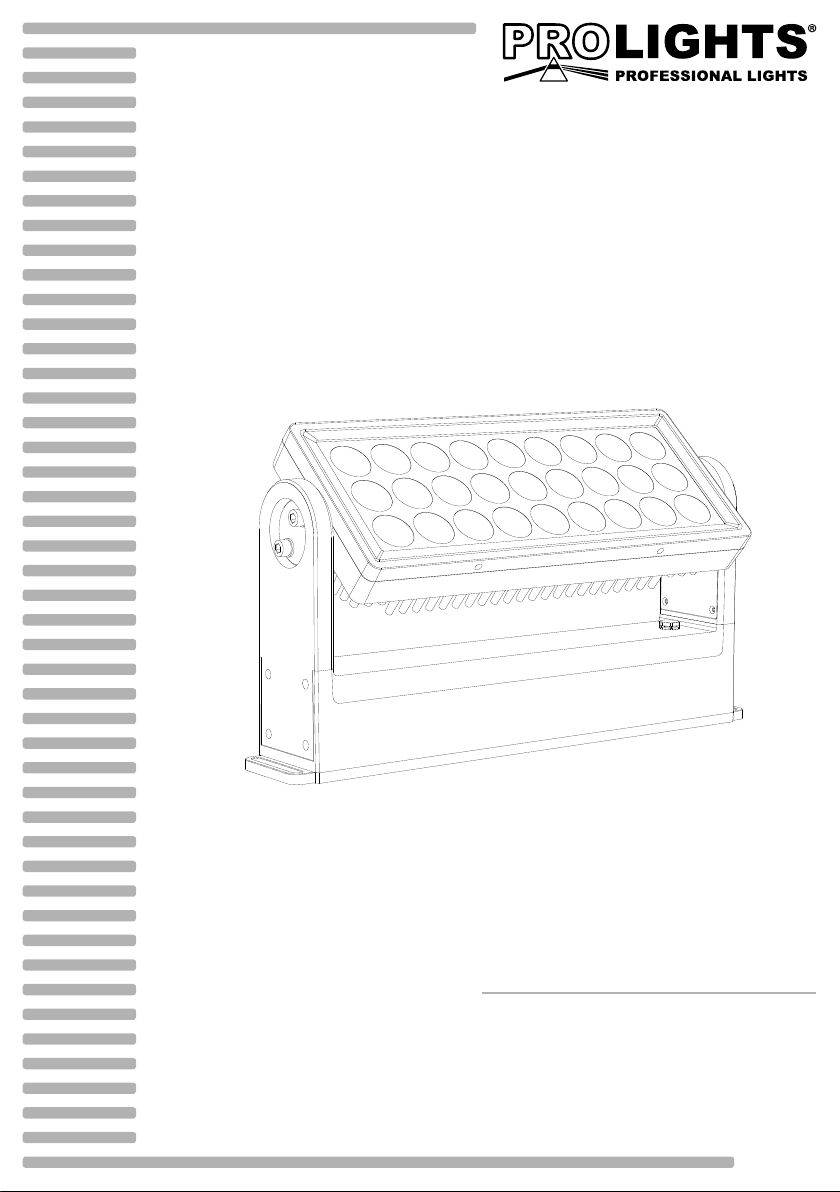
ARCPOD27Q
OUTDOOR COMPACT WASHLIGHT
USER MANUAL
MANUALE UTENTE
EN - IT
Page 2

All rights reserved by Music & Lights S.r.l. No part of this instruction manual may be
reproduced in any form or by any means for any commercial use.
In order to improve the quality of products, Music&Lights S.r.l. reserves the right to modify the characteris-
tics stated in this instruction manual at any time and without prior notice.
All revisions and updates are available in the ‘manuals’ section on site www.musiclights.it
REV. 02-12/18
Page 3

ARCPOD27Q
1
TABLE OF CONTENTS
Safety
General instructions
Warnings and installation precautions
1 Introduction
1. 1 Description
1. 2 Technical specications
1. 3 Operating elements and connections
2 Installation
2. 1 Mounting
3 Functions and settings
3. 1 Operation
3. 2 Basic
3. 3 RDM mode
3. 4 RDM function
3. 5 Linking
3. 6 DMX addressing conguration
3. 7 DMX mode conguration
3. 8 DMX addressing
3. 9 LED frequency
3. 10 Sensor menu
3. 11 Sw version
3. 12 UID
3. 13 Factory Default
3. 14 Manual color
3. 15 Eects
3. 16 Connection of the DMX line
3. 17 Construction of the DMX termination
3. 18 DMX control
2
2
3
3
5
6
7
7
8
8
9
9
9
9
10
10
10
10
11
11
11
12
12
13
Packing content
4 Maintenance
4. 1 Maintenance and cleaning the unit
4. 2 Trouble shooting
• ARCPOD27Q
• Power adaptor cable
• Signal adaptor cable (2 pcs)
• User manual
16
16
Page 4
2
WARNING! Before carrying out any operations with the unit, carefully read this instruction
manual and keep it with cure for future reference. It contains important information about
the installation, usage and maintenance of the unit.
ARCPOD27Q
SAFETY
General instruction
• The products referred to in this manual conform to the European Community Directives and are therefore marked with .
• The unit is supplied with hazardous network voltage (230V~). Leave servicing to skilled personnel only.
Never make any modications on the unit not described in this instruction manual, otherwise you will
risk an electric shock.
• Connection must be made to a power supply system tted with ecient earthing (Class I appliance according to standard EN 60598-1). It is, moreover, recommended to protect the supply lines of the units
from indirect contact and/or shorting to earth by using appropriately sized residual current devices.
• The connection to the main network of electric distribution must be carried out by a qualied electrical
installer. Check that the main frequency and voltage correspond to those for which the unit is designed
as given on the electrical data label.
• This unit is not for home use, only professional applications.
• Never use the xture under the following conditions:
- in places subject to vibrations or bumps;
- in places with an ambient temperature of over 50°C.
• Make certain that no inammable liquids, water or metal objects enter the xture.
• Do not dismantle or modify the xture.
• All work must always be carried out by qualied technical personnel. Contact the nearest sales point for
an inspection or contact the manufacturer directly.
• If the unit is to be put out of operation denitively, take it to a local recycling
plant for a disposal which is not harmful to the environment.
Warnings and installation precautions
• If this device will be operated in any way dierent to the one described in this manual, it may suer
damage and the guarantee becomes void. Furthermore, any other operation may lead to dangers like
short circuit, burns, electric shock, etc.
• Before starting any maintenance work or cleaning the projector, cut o power from the main supply.
• When carrying out any work, always comply scrupulously with all the regulations (particularly regarding safety) currently in force in the country in which the xture’s being used.
• The minimum distance between the xture and surrounding walls must be more than 50 cm and the
air vents at the housing must not be covered in any case.
• Keep any inammable material at a safe distance from the xture.
• The maximum temperature that can be reached on the external surface of the tting, in a thermally
steady state, is high. After power o, please cool down over 15 minutes.
• Shields, lenses or ultraviolet screens shall be changed if they have become damaged to such an extent
that their eectiveness is impaired.
• The lamp (LED) shall be changed if it has become damaged or thermally deformed.
• Never look directly at the light beam. Please note that fast changes in lighting, e. g. ashing light, may
trigger epileptic seizures in photosensitive persons or persons with epilepsy.
• This product was designed and built strictly for the use indicated in this documentation. Any other use,
not expressly indicated here, could compromise the good condition/operation of the product and/or
be a source of danger. We decline any liability deriving from improper use of the product
Page 5

ARCPOD27Q
3
- 1 - INTRODUCTION
1.1 DESCRIPTION
ARCPOD27Q is a compact high-power outdoor wash light featuring an outstanding brightness of 11,480
lumens. Equipped with 27x10W RGBW full colour LEDs, delivering superior colour mixing. The slim sizing,
as well as the wide range of available optics through the magnet, makes the ARCPOD27Q an incredibly
exible and versatile device for large outdoor applications.
1.2 TECHNICAL SPECIFICATIONS
LIGHT SOURCE
• Source: 27X10W RGBW/FC LEDs
• CT: 5960K
• CRI: 71.8
• Luminous ux: @full 11480lm
• Lux: 15° @full 11276lux @3m
• Lux: 15° @full 4060lux @5m
• Source life expectancy: >50.000 h
OPTICS
• Beam angle: 15°
• Field angle: 28°
• Lens diameter: 36mm
• Lens type: honeycomb gapless plano convex optics
• Additional optics: 10°, 25°, 45°
• Other: barn doors not included
COLOUR SYSTEM
• Colour mixing: RGBW/FC
• CTC: CTC control through independent DMX channel
• Colour wheel: virtual colour wheel with presets
• Macros: several pre-build macros with adjustable speed
DYNAMIC EFFECTS
• Static colour mode: selection of static colour
• Manual colour mode: manual adjustment of colour
• Auto mode: built-in programs with execution speed adjustment
BODY
• Tilt angle: +/- 90 ° Manual°
• Body: sturdy die-cast aluminium body conceived for long-time durability
• Body colour: grey
CONTROL
• Protocols: DMX512, RDM
• DMX channels: 5, 7, 10, 13, 17 channel
• Pixel control: 3 horizontal individual sections controlled
• RDM: RDM ready for xture remote monitor and settings
• Display: user interface through DATAMASTER external coder (not included)
Page 6
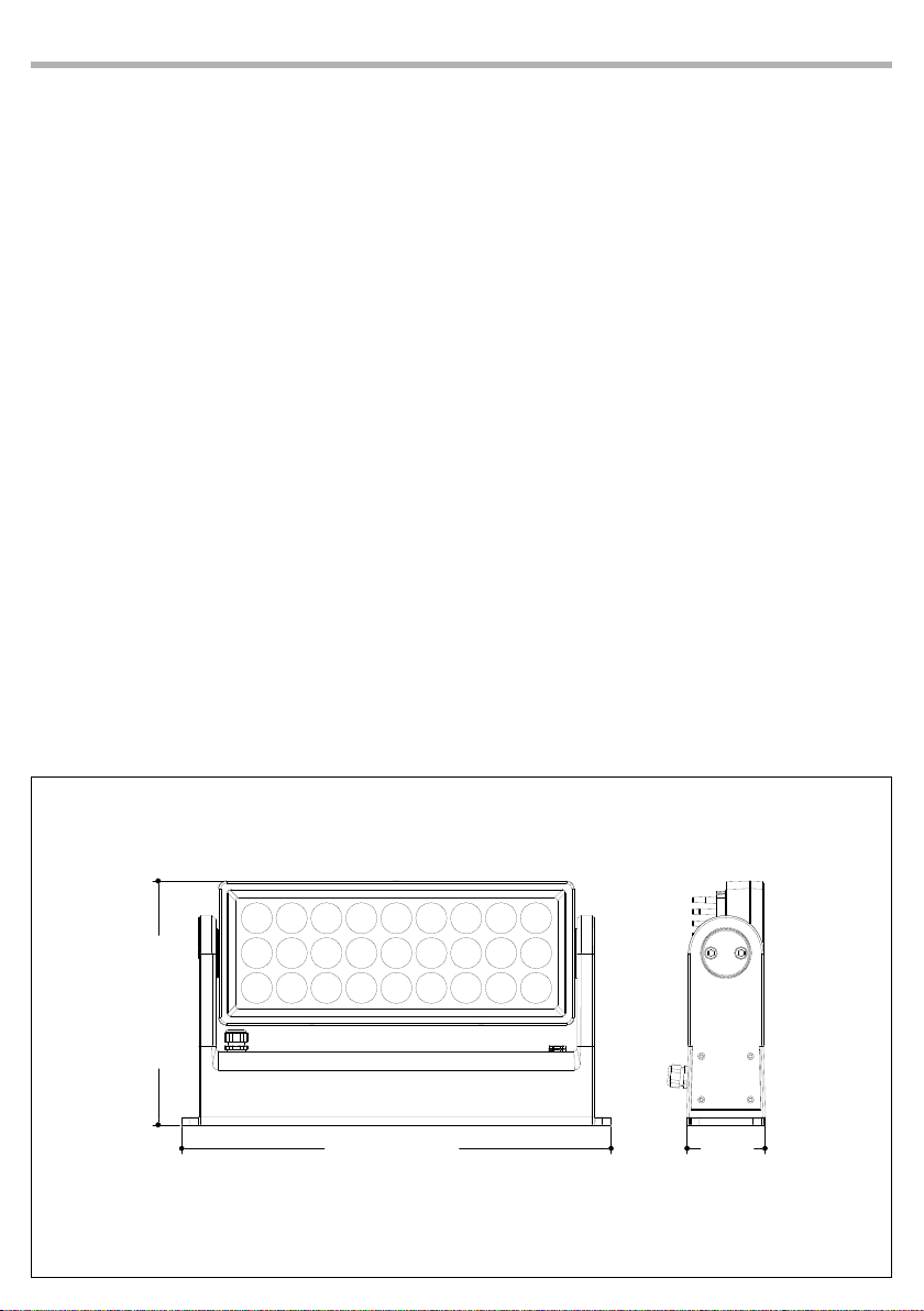
4
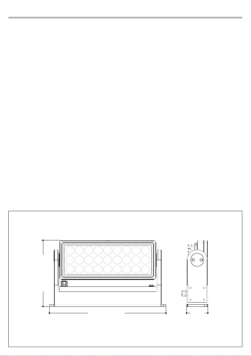
258mm/10.15in
3.26in
ARCPOD27Q
• Firmware upgrade: yes, via USB-DMX interface (UPBOX1) not included
• Master/Slave: for synchronized operation of more units linked in a chain
ELECTRONICS
• Dimmer: linear 0~100% electronic dimmer
• Operating temperature: -20° ~ +50°
• Flicker: icker free operation
• Selectable PWM: 600~25K Hz
ELECTRICAL
• Power supply: 100-240V – 50/60Hz
• Power consumption (at 230V): 268W
• Power consumption (at 120V): 275W
• Output (at 230V): 9 units on a single power line
• Output (at 120V): 5 units on a single power line
• Power factor: 0,994
PHYSICAL
• Cooling: natural cooling of the peculiar chassis and to absence of fans
• Signal connection: IP IN/OUT DMX connector
• Power connection: IP IN/OUT power connector
• IP rating: 65
• Dimensions (WxHxD): 454x153x268.5mm
• Weight: 9kg
455mm/17.91in
83mm/
Technical drawing Fig.1
Page 7
ARCPOD27Q
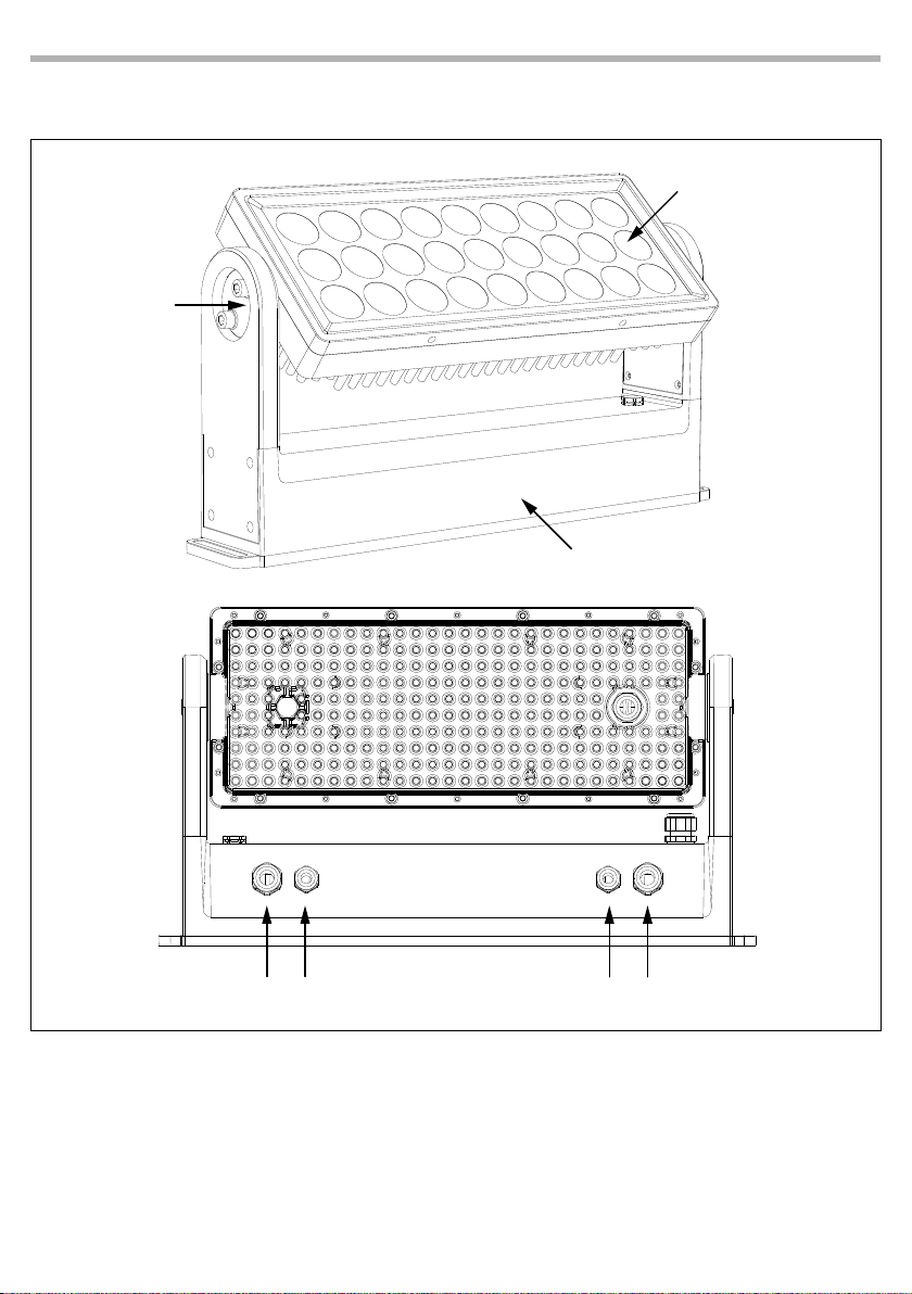
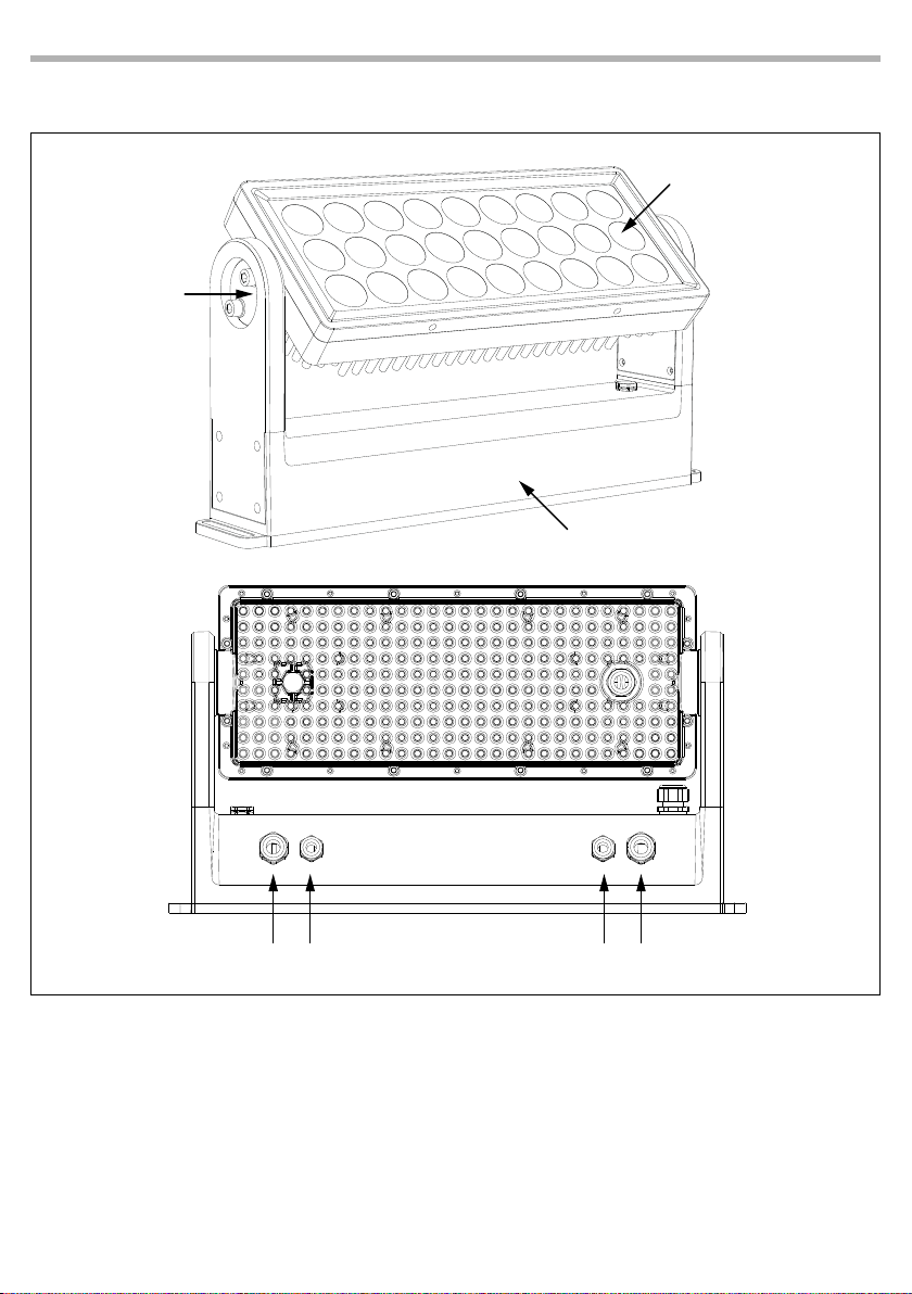
1.3 OPERATING ELEMENTS AND CONNECTIONS
2
5
1
3
1. LED panel
2. MECHANICAL SYSTEM for individual positioning of Led panels
3. POWER SUPPLY CASING SET
4. POWER IN: for connection to a socket (100-240V~/50-60Hz) via the
supplied mains cable
5. DMX IN DMX IN (5-pole XLR): 1 = ground, 2 = DMX-, 3 = DMX+, 4
N/C, 5 N/C.
6. DMX OUT DMX OUT (5-pole XLR): 1 = ground, 2 = DMX-, 3 = DMX+,
4 N/C, 5 N/C.
7. POWER OUT: connect to supply power to the next unit.
Fig.2
Page 8
6
ARCPOD27Q
- 2 - INSTALLATION
2.1 MOUNTING
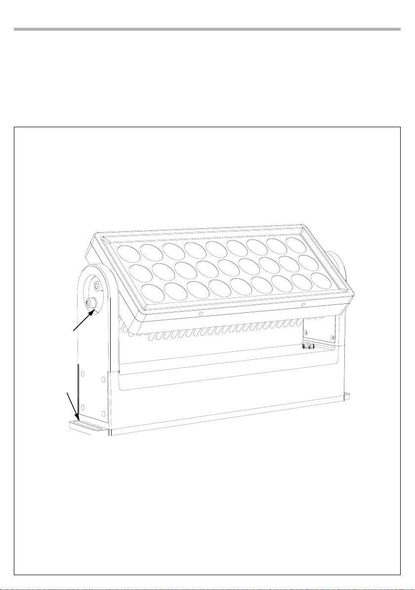
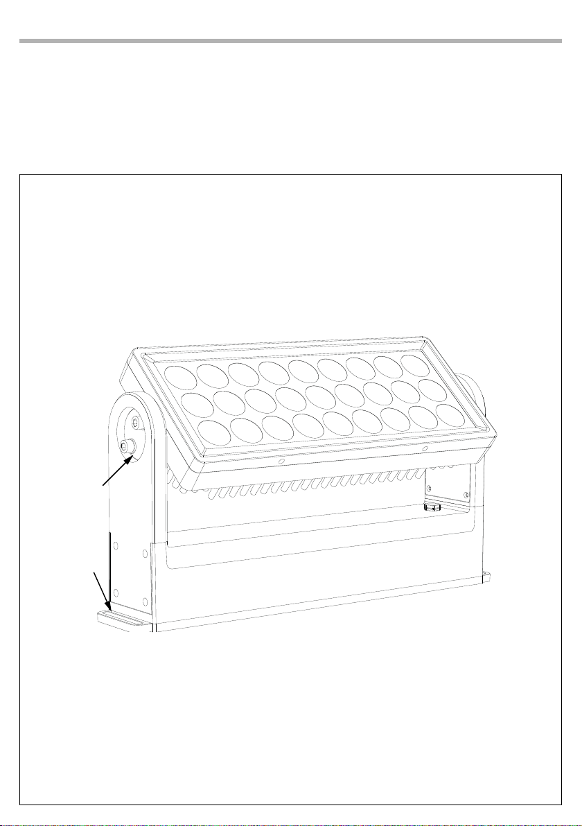
ARCPOD27Q can be set on a solid and uniform surface using the fastening devices of the base plate (g.3).
Stable mounting clips are required for xing.
Also make sure to comply with all safety warnings.
1
2
Fig.3
Page 9
ARCPOD27Q
7
- 3 - FUNCTIONS AND SETTINGS
3.1 OPERATION
Connect the supplied main cable to a socket (100-240V~/50-60Hz). The unit will run built-in program to
reset all motors to their home position. Shortly after that the ARCPOD27Q is ready for operation. To switch
o, disconnect the mains plug from the socket. For a more convenient operation it is recommended to
connect the unit to a socket which can be switched on and o via light switch.
3.2 BASIC
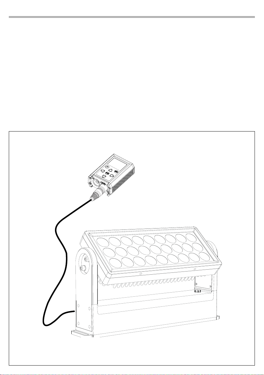
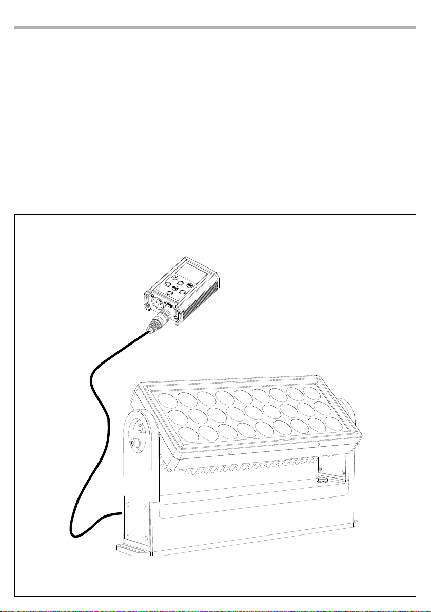
To control the ARCPOD27Q connect the device to a DATAMASTER (g.4).
DATAMASTER is a powerful RDM-DMX tool that automatically detects connected RDM devices, allowing
direct and fast monitoring and control. Information on the status of the connected xture can be read
from the DATAMASTER display.
DMX OUT
Fig.4
Page 10
8
3.3 RDM MODE
To use the ARCPOD27Q proceed as follows:
• Connect the ARCPOD27Q to a DATAMASTER.
• Turn on the DATAMASTER using the dedicated button.
• With the DATAMASTER select RDM to show the following info about:
• Model;
• Manufacturer;
• Function;
• Temperature;
• Factory Default;
• Software Version;
• UID.
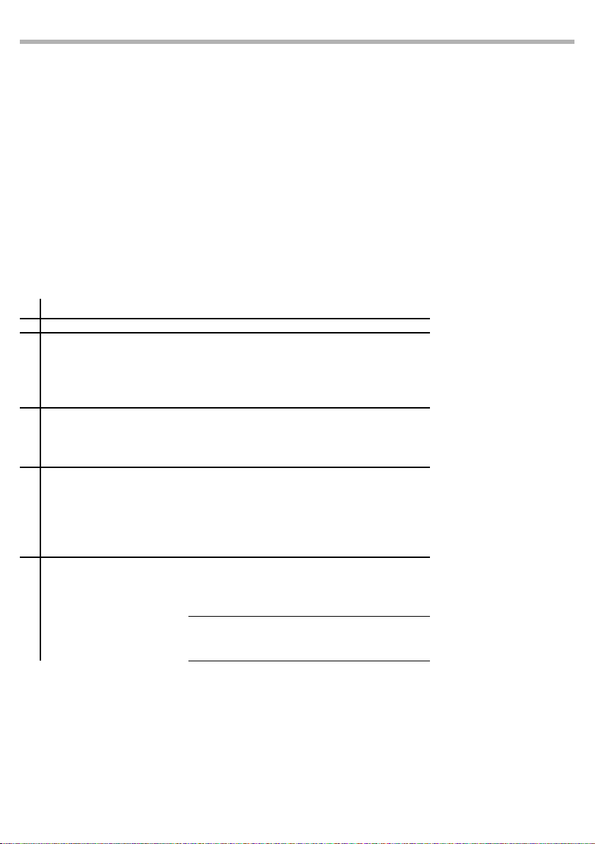
3.4 MENU STRUCTURE
MENU
1 DMX ADDRESS
2 DMX MODE
3 DIMMER MODE
4 LED FREQUENCY
5 SPECIFIC PIDS
6 FULL ON MODE
ð
ð
ð
ð
ð
ð
ARCPOD27Q
001-512 Default: 1
5CH
7CH
10CH
13CH
17CH
O
Dimmer1
Dimmer2
Dimmer3
600Hz
1200Hz
2000Hz
4000Hz
6000Hz
25kHz
8200 (RED)
8201 (Green)
8202 (Blue)
8203 (White)
HB MODE
STUDIO MODE
Default: 10CH
Default: O
Default: 1200Hz
White Balance
HB MODE (STUDIO MODE is
auto balance mode at 6000K
for colors at full)
Page 11

ARCPOD27Q
9
3.5 LINKING
Multiple units can be connected so that all secondary units have the same lighting eect as the main unit
(Master).
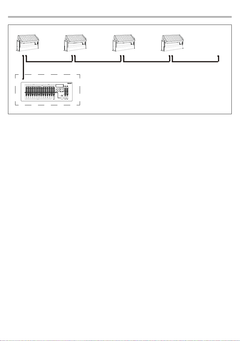
1. 1. Connect the DMX OUT output of the main unit to the DMX IN input of the rst secondary unit using
5 pole XLR cable.
2. 2. Connect the DMX OUT output of the rst secondary unit with the DMX IN input of the second secondary unit, etc.
3.6 DMX ADDRESSING CONFIGURATION
To enter the DMX mode proceed as follows:
• In the main menu of the DATAMASTER select RDM.
• Press the ENTER button to access the main menu.
• Press the UP/DOWN button to scroll through the menu, select the Start Addrees, then press the ENTER
button to access.
• Use the arrow buttons to set the desired value (001-512). Press the ENTER button to conrm.
• Press the MENU button repeatedly to exit the menu and to save the changes made.
3.7 DMX MODE CONFIGURATION
ARCPOD27Q has 5 DMX channel congurations.
• In the main menu of the DATAMASTER select RDM
• Press the ENTER button to access the main menu.
• Press the UP/DOWN button to scroll through the menu, select the Pers. Mode, then press the ENTER but-
ton to enter the next menu.
• Use the UP/DOWN button to select the desired DMX channel conguration (5CH, 7CH, 10CH, 13CH, 17CH),
then press the ENTER button to conrm the selection.
• Press the MENU button repeatedly to exit the menu and to save the changes made.
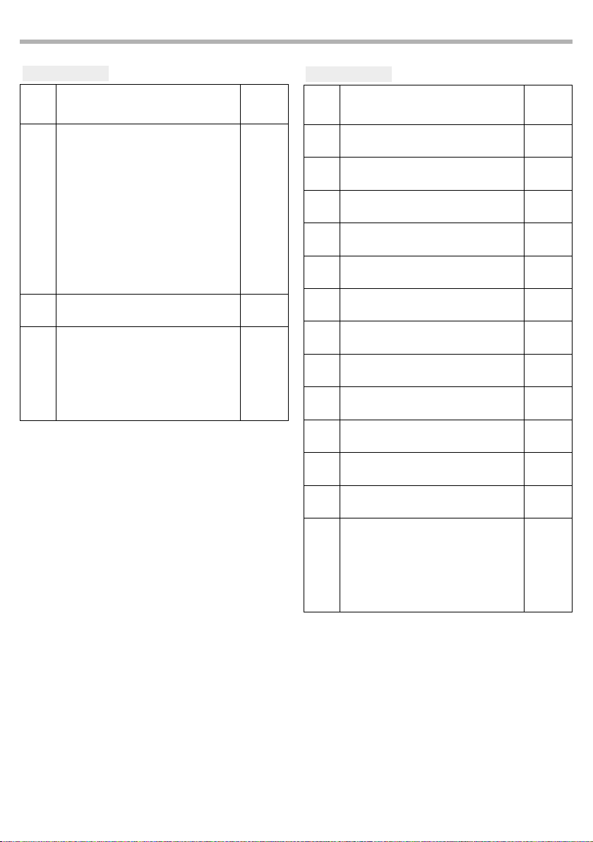
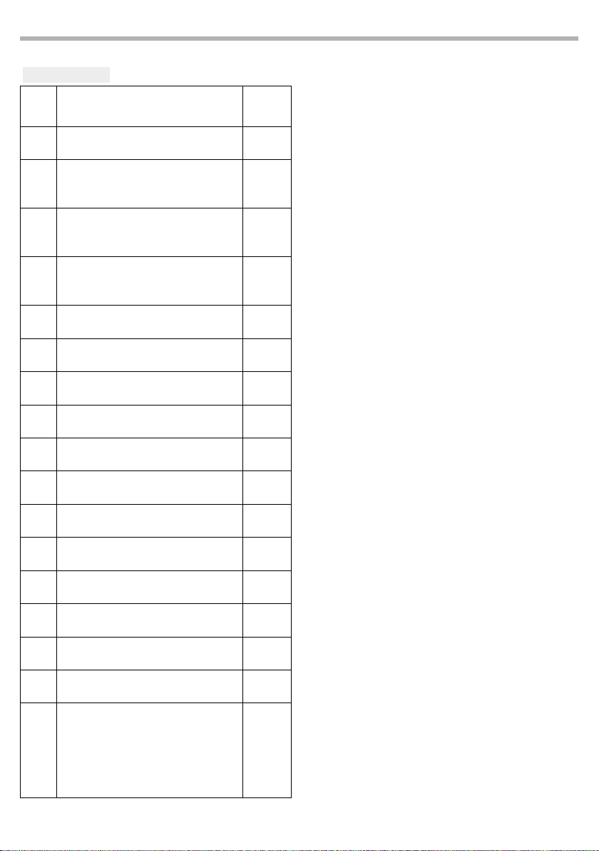
The tables on page 13, 14 and 15 indicate the operating modes and related DMX values. As an interface
DMX, the unit has 5-pin XLR contacts.
3.8 DMX ADDRESSING
For operation via a light control unit with DMX512 protocol, simply connect ARCPOD27Q to the controller.
The projector has a DMX channel conguration that can be accessed from the control panel. In order to
control ARCPOD27Q with a light control unit, the DMX start address must be set for the rst DMX channel.
If, for example, the address 33 is provided on the control unit to control the function of the rst DMX channel, the start address 33 must be set on the ARCPOD27Q. The other panel functions will be automatically
assigned to the following addresses.
Number of
DMX chan-
nels
Start address
(example)
DMX Address
occupied
Next possible start
address for unit No. 1
Next possible start
address for unit No. 2
Next possible start
address for unit No. 3
5 33 33-37 38 43 48
7 33 33-39 40 47 54
10 33 33-42 43 53 63
13 33 33-45 46 59 72
17 33 33-49 50 67 84
Page 12
10
DMX512 Controller
ARCPOD27Q
DMX Address:53DMX Address: 43DMX Address: 38 DMX Address: 48
. . . . . . . . . . . .
Fig.5 - Example of a DMX 5-channel conguration
3.9 LED FREQUENCY
To view the information about temperature on the device, proceed as follows.
• In the main menu of the DATAMASTER select RDM.
• Press the ENTER button to access the main menu.
• Press the UP/DOWN button to scroll through the menu, select the LED Frequency, then press the ENTER
button to access to next menù.
• Press the UP/DOWN button to select one of available setting: 600Hz, 1200Hz, 2000Hz, 4000Hz, 6000Hz,
25kH. Then select ENTER to conrm
• Press the MENU button repeatedly to exit the menu.
3.10 SENSOR MENU
To view the information about temperature on the device, proceed as follows.
• In the main menu of the DATAMASTER select RDM.
• Press the ENTER button to access the main menu.
• Press the UP/DOWN button to scroll through the menu, select the Sensor Menu, then press the ENTER button to access to next menù to view the temperature.
• Press the MENU button repeatedly to exit the menu.
3.11 SW VERSION
To view the software version installed on the device, proceed as follows.
• In the main menu of the DATAMASTER select RDM.
• Press the ENTER button to access the main menu.
• Press the UP/DOWN button to scroll through the menu, select the Sw Version, then press the ENTER but-
ton to access to next menù to view the software version of the device.
• Press the MENU button repeatedly to exit the menu.
3.12 UID
To view the UID of the device, proceed as follows.
• In the main menu of the DATAMASTER select RDM.
• Press the ENTER button to access the main menu.
• Press the UP/DOWN button to scroll through the menu, select the UID, then press the ENTER button to
access to access to next menù to view UID of the device.
Press the MENU button repeatedly to exit the menu.
Page 13

ARCPOD27Q
3.13 FACTORY DEFAULT
To reset the device of the factory default proceed as follows:
• In the main menu of the DATAMASTER select RDM.
• Press the ENTER button to access the main menu.
• Press the UP/DOWN button to scroll through the menu, select the Factory Default, then press the ENTER
button to access the next menù to choice the Yes or No.
• Press the MENU button repeatedly to exit the menu and to save the changes made.
3.14 MANUAL COLOR
To enter this mode proceed as follows:
• In the main menu of the DATAMASTER select Stand Alone.
• Press the ENTER button to access the main menu.
• Press the UP/DOWN button to scroll through the menu, select the Manual Color then press the ENTER button to access.
• Use the arrow buttons to set the desired mixing color (Red, Green, Blue, White) with the relative value (000-
255). Press the ENTER button to conrm.
• Press the MENU button repeatedly to exit the menu and to save the changes made.
• NOTE: once you have set up the mixing of desired colors with the mode described, to change this at a
later time it is necessary to start again with the Factory Reload mode.
3.15 EFFECTS
To enter this mode proceed as follows:
• In the main menu of the DATAMASTER select Eects.
• Press the ENTER button to access the main menu.
• Press the UP/DOWN button to scroll through the menu, select the Eects then press the ENTER button
to access.
• Use the arrow buttons to set the desired eect (Eect1, Eect2, Eect3, Eect4, Eect5) with the relative value
(000-125). Press the ENTER button to conrm.
• Press the MENU button repeatedly to exit the menu and to save the changes made.
• NOTE: once the desired eect has been set with the described mode, to change it at a later time it is
necessary to start again with the Factory Reload mode.
11
NOTE: If the projector is in Blackout mode before to receive DMX signal, and if the DMX signal is lost, the
projector will remain on according to the last received DMX value. If the projector was in STATIC or AUTO
mode before to receive DMX signal, if the DMX signal is lost, the projector will return to the previously set
STATIC or AUTO.
Page 14
12
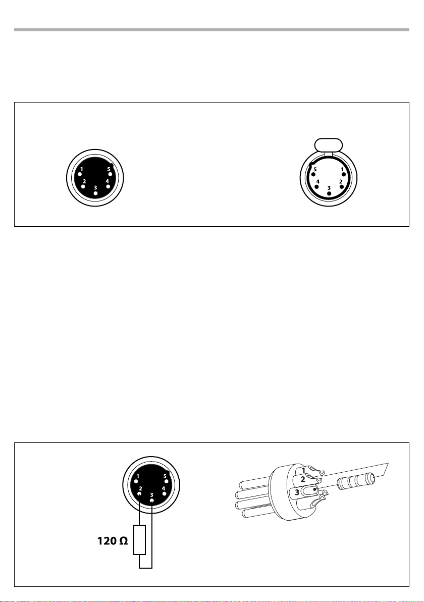
3.16 CONNECTION OF THE DMX LINE
DMX connection employs standard XLR connectors. Use shielded pair-twisted cables with 120Ω impedance and low capacity.
The following diagram shows the connection mode:
ARCPOD27Q
DMX - INPUT
XLR plug
Pin1 : GND - Shield
Pin2 : - Negative
Pin3 : + Positive
Pin4 : N/C
Pin5 : N/C
ATTENTION
The screened parts of the cable (sleeve) must never be connected to the system’s earth, as this would
cause faulty xture and controller operation.
Over long runs can be necessary to insert a DMX level matching amplier.
For those connections the use of balanced microphone cable is not recommended because it cannot
transmit control DMX data reliably.
• Connect the controller DMX input to the DMX output of the rst unit.
• Connect the DMX output to the DMX input of the following unit. Connect again the output to the input
of the following unit until all the units are connected in chain.
• When the signal cable has to run longer distance is recommended to insert a DMX termination on the
last unit.
3.17 CONSTRUCTION OF THE DMX TERMINATION
The termination avoids the risk of DMX 512 signals being reected back along the cable when they reaches the end of the line: under certain conditions and with certain cable lengths, this could cause them to
cancel the original signals.
The termination is prepared by soldering a 120Ω 1/4 W resistor between pins 2 and 3 of the 5-pin male XLR
connector, as shown in gure.
DMX - OUTPUT
XLR socket
Fig.6
Example:
5 pin XLR connector
Fig.7
Page 15

3.18 DMX CONTROL
ARCPOD27Q
13
5 CHANNEL
MODE
FUNCTION DMX
5 Ch
RED
1
0~100% 000 - 255
GREEN
2
0~100% 000 - 255
BLUE
3
0~100% 000 - 255
WHITE
4
0~100% 000 - 255
DIMMER SPEED MODE
Preset dimmer speed from display menu
Dimmer speed mode o
5
Dimmer speed mode1 (fast speed)
Dimmer speed mode2 (middle speed)
Dimmer speed mode3 (slow speed)
7 CHANNEL
MODE
FUNCTION DMX
7 Ch
DIMMER
1
0~100% 000 - 255
RED
2
0~100% 000 - 255
GREEN
3
0~100% 000 - 255
BLUE
4
0~100% 000 - 255
WHITE
5
0~100% 000 - 255
STROBE
6
No function
Strobe Slow to Fast
DIMMER SPEED MODE
Preset dimmer speed from display menu
Dimmer speed mode o
7
Dimmer speed mode1 (fast speed)
Dimmer speed mode2 (middle speed)
Dimmer speed mode3 (slow speed)
Value
000-051
052-101
102-152
153-203
204-255
Value
000 - 010
011 - 255
000-051
052-101
102-152
153-203
204-255
10 CHANNEL
MODE
FUNCTION DMX
10 Ch
DIMMER
1
0~100% 000 - 255
RED
2
0~100% 000 - 255
GREEN
3
0~100% 000 - 255
BLUE
4
0~100% 000 - 255
WHITE
5
0~100% 000 - 255
STROBE
6
No function
Strobe Slow to Fast
COLOR MACRO
No Function
R 100%, G 0~100%, B 0 %
R 100%~0 %, G 100%, B 0 %
R 0 %, G 100%, B 0~100%
R 0 %, G 100~0 %, B 100%
R 0~100%, G 0 %, B 100%
R 100%, G 0 %, B 100~0 %
R 100%, G 0~100%, B 0~100%
R 100~0 %, G 100~0 %, B 100%
R 100%, G 100%, B 100%, W 100%
7
Color 1
Color 2
Color 3
Color 4
Color 5
Color 6
Color 7
Color 8
Color 9
Color 10
Color 11
Value
000 - 010
011 - 255
000 - 010
011 - 030
031 - 050
051 - 070
071 - 090
091 - 110
111 - 130
131 - 150
151 - 170
171 - 200
201 - 205
206 - 210
211 - 215
216 - 220
221 - 225
226 - 230
231 - 235
236 - 240
241 - 245
246 - 250
251 - 255
Page 16
14
ARCPOD27Q
10 CHANNEL
MODE
FUNCTION DMX
10 Ch
EFFECTS
NO Function
Eect 1
Eect 2
Eect 3
8
Eect4
Eect5 (Eects1- 4)
Eect 6
Eect 7
Eect 8
Eect 9 (Eects6- 8)
EFFECTS SPEED
9
Eects speed slow to fast 000 - 255
DIMMER SPEED MODE
Preset dimmer speed from display menu
Dimmer speed mode o
10
Dimmer speed mode 1 (fast speed)
Dimmer speed mode 2 (middle speed)
Dimmer speed mode 3 (slow speed)
Value
000-010
011-037
038-064
065-091
092-118
119-145
146-172
173-199
200-226
227-255
000 - 051
052 - 101
102 - 152
153 - 203
204 - 255
13 CHANNEL
MODE
FUNCTION DMX
13 Ch
RED 1
1
0~100% 000 - 255
GREEN 1
2
0~100% 000 - 255
BLUE 1
3
0~100% 000 - 255
WHITE 1
4
0~100% 000 - 255
RED 2
5
0~100% 000 - 255
GREEN 2
6
0~100% 000 - 255
BLUE 2
7
0~100% 000 - 255
WHITE 2
8
0~100% 000 - 255
RED 3
9
0~100% 000 - 255
GREEN 3
10
0~100% 000 - 255
BLUE 3
11
0~100% 000 - 255
WHITE 3
12
0~100% 000 - 255
DIMMER SPEED MODE
Preset dimmer speed from display menu
Dimmer speed mode o
13
Dimmer speed mode1 (fast speed)
Dimmer speed mode2 (middle speed)
Dimmer speed mode3 (slow speed)
Value
000-051
052-101
102-152
153-203
204-255
Page 17
17 CHANNEL
MODE
FUNCTION DMX
17 Ch
DIMMER
1
0~100% 000 - 255
STROBE 1
2
No function
Strobe Slow to Fast
STROBE 2
3
No function
Strobe Slow to Fast
STROBE 3
4
No function
Strobe Slow to Fast
RED 1
5
0~100% 000 - 255
GREEN 1
6
0~100% 000 - 255
BLUE 1
7
0~100% 000 - 255
WHITE 1
8
0~100% 000 - 255
RED 2
9
0~100% 000 - 255
GREEN 2
10
0~100% 000 - 255
BLUE 2
11
0~100% 000 - 255
WHITE 2
12
0~100% 000 - 255
RED 3
13
0~100% 000 - 255
GREEN 3
14
0~100% 000 - 255
BLUE 3
15
0~100% 000 - 255
WHITE 3
16
0~100% 000 - 255
DIMMER SPEED MODE
Preset dimmer speed from display menu
Dimmer speed mode o
17
Dimmer speed mode1 (fast speed)
Dimmer speed mode2 (middle speed)
Dimmer speed mode3 (slow speed)
ARCPOD27Q
Value
000 - 010
011 - 255
000 - 010
011 - 255
000 - 010
011 - 255
000-051
052-101
102-152
153-203
204-255
15
Page 18

16
ARCPOD27Q
- 4 - MAINTENANCE
4.1 MAINTENANCE AND CLEANING THE UNIT
• Make sure the area below the installation place is free from unwanted persons during setup.
• Switch o the unit, unplug the main cable and wait until the unit has cooled down.
• All screws used for installing the device and any of its parts should be tightly fastened and should not
be corroded.
• Housings, xations and installation spots (ceiling, trusses, suspensions) should be totally free from any
deformation.
• When the lens is visibly damaged due to cracks or deep scratches, it must be replaced.
• The main cables must be in impeccable condition and should be replaced immediately even when a
small problem is detected.
• In order to protect the device from overheating the cooling fans (if any), and ventilation openings
should be cleaned monthly.
To ensure optimal operation and performance for a long time it is essential to periodically clean the parts
subject to dust and grease deposits. The frequency with which the following operations are to be carried
out depends on various factors, such as the amount of the eects and the quality of the working environment (air humidity, presence of dust, salinity, etc.). Use a soft cloth dampened with any detergent liquid
for cleaning glass to remove the dirt from the reectors, from the lenses and lters.
It is recommended that the projector undergoes an annual service by a qualied technician for special
maintenance involving at least the following operations:
- General cleaning of internal parts..
- Restoring lubrication of all parts subject to friction, using lubricants specically.
- General visual check of the internal components, cabling, mechanical parts, etc.
- Electrical, photometric and functional checks; eventual repairs.
Warning: we strongly recommend internal cleaning to be carried out by qualied personnel!
4.2 TROUBLESHOOTING
Problems Possible causes Checks and remedies
• No mains supply
• Dimmer fader set to 0
Fixture does not light up
General low light intensity
Fixture does not power up
Fixture does not respond to DMX
• All color faders set to 0
• Faulty LED
• Faulty LED board
• Dirty lens assembly
• Misaligned lens assembly
• No power
• Loose or damaged power cord
• Faulty internal power supply
• Wrong DMX addressing
• Damaged DMX cables
• Bouncing signals
Contact an authorized service center in case of technical problems or not reported in the table can not be
resolved by the procedure given in the table.
• Check the power supply voltage
• Increase the value of the dimmer channels
• Increase the value of the color channels
• Replace the LED board
• Replace the LED board
• Clean the xture regularly
• Install lens assembly properly
• Check for power on power outlet
• Check power cord
• Replace internal power supply
• Check control panel and unit addressing
• Check DMX cables
• Install terminator as suggested
Page 19

Page 20

Music & Lights S.r.l. si riserva ogni diritto di elaborazione in qualsiasi forma delle presenti istruzioni per l’uso.
Al ne di migliorare la qualità dei prodotti, la Music&Lights S.r.l. si riserva la facoltà di modicare, in qualun-
que momento e senza preavviso, le speciche menzionate nel presente manuale di istruzioni.
Tutte le revisioni e gli aggiornamenti sono disponibili nella sezione 'Manuali' sul sito www.musiclights.it
La riproduzione - anche parziale - per propri scopi commerciali è vietata.
REV.002-12/18
Page 21

ARCPOD27Q
3
INDICE
Sicurezza
Avvertenze generali
Attenzioni e precauzioni per l’installazione
1 Introduzione
1. 1 Descrizione
1. 2 Speciche tecniche
1. 3 Elementi di comando e di collegamento
2 Installazione
2. 1 Montaggio
3 Funzioni e impostazioni
3. 1 Funzionamento
3. 2 Impostazione base
3. 3 Modalità RDM
3. 4 Funzioni RDM
3. 5 Collegamento
3. 6 Congurazione indirizzamento DMX
3. 6 Congurazione modalità DMX
3. 7 Indirizzamento DMX
3. 8 LED frequency
3. 9 Sensor menù
3. 10 SW version
3. 11 UID
3. 12 Factory default
3. 13 Eects
3. 14 Manual
3. 15 Collegamenti della linea DMX
3. 16 Costruzione del terminatore DMX
3. 17 Canali DMX
4
4
5
5
7
8
9
9
10
10
11
11
11
11
12
12
12
12
13
13
13
14
14
15
Contenuto dell'imballo:
4 Manutenzione
4. 1 Manutenzione e pulizia del sistema ottico
4. 2 Risoluzione dei problemi
• ARCPOD27Q
• Adattatore cavo di alimentazione
• Adattatore cavo di segnale (2 pz)
• Manuale utente
18
19
Page 22
4
ATTENZIONE! Prima di effettuare qualsiasi operazione con l’unità, leggere con attenzione
questo manuale e conservarlo accuratamente per riferimenti futuri. Contiene informazioni
importanti riguardo l’installazione, l’uso e la manutenzione dell’unità.
ARCPOD27Q
SICUREZZA
Avvertenze generali
• I prodotti a cui questo manuale si riferisce sono conformi alle Direttive della Comunità Europea e pertanto recano la sigla .
• Il dispositivo funziona con pericolosa tensione di rete 230V~. Non intervenire mai al suo interno al di
fuori delle operazioni descritte nel presente manuale; esiste il pericolo di una scarica elettrica.
• È obbligatorio eettuare il collegamento ad un impianto di alimentazione dotato di un’eciente messa
a terra (apparecchio di Classe I secondo norma EN 60598-1). Si raccomanda, inoltre, di proteggere le
linee di alimentazione delle unità dai contatti indiretti e/o cortocircuiti verso massa tramite l’uso di
interruttori dierenziali opportunamente dimensionati.
• Le operazioni di collegamento alla rete di distribuzione dell’energia elettrica devono essere eettuate
da un installatore elettrico qualicato. Vericare che frequenza e tensione della rete corrispondono alla
frequenza ed alla tensione per cui l’unità è predisposta, indicate sulla targhetta dei dati elettrici.
• L’unità non per uso domestico, solo per uso professionale.
• Evitare di utilizzare l’unità:
- in luoghi soggetti a vibrazioni, o a possibili urti;
- in luoghi a temperatura superiore ai 50°C.
• Evitare che nell’unità penetrino liquidi inammabili, acqua o oggetti metallici.
• Non smontare e non apportare modiche all’unità.
• Tutti gli interventi devono essere sempre e solo eettuati da personale tecnico qualicato. Rivolgersi al
più vicino centro di assistenza tecnica autorizzato.
• Se si desidera eliminare il dispositivo denitivamente, consegnarlo
per lo smaltimento ad un’istituzione locale per il riciclaggio.
Attenzioni e precauzioni per l’installazione
• Se il dispositivo dovesse trovarsi ad operare in condizioni dierenti da quelle descritte nel presente
manuale, potrebbero vericarsi dei danni; in tal caso la garanzia verrebbe a decadere. Inoltre, ogni altra
operazione potrebbe provocare cortocircuiti, incendi, scosse elettriche, rotture etc.
• Prima di iniziare qualsiasi operazione di manutenzione o pulizia sull’unità togliere la tensione dalla rete
di alimentazione.
• Nell’eseguire qualsiasi intervento attenersi scrupolosamente a tutte le normative (in materia di sicurezza) vigenti nel paese di utilizzo.
• La distanza minima tra il proiettore e le pareti circostanti deve essere superiore a 50 cm e non devono
essere ostruite, in nessun caso, le aperture di aerazione.
• Mantenere i materiali inammabili ad una distanza di sicurezza dall’unità.
• La temperatura massima raggiungibile sulla supercie esterna dell’unità, in condizioni di regime termico, è elevata. Dopo lo spegnimento, attendere 15 minuti per il rareddamento.
• I ltri, le lenti o gli schermi ultravioletti se danneggiati possono limitare la loro ecienza.
• I LED devono essere sostituiti se danneggiati o termicamente deformati.
• Non guardare direttamente il fascio luminoso. Tenete presente che i veloci cambi di luce possono provocare attacchi d’epilessia presso persone fotosensibili o epilettiche.
• Questo prodotto è stato progettato e costruito per l’utilizzo indicato in questa documentazione. Qualsiasi altro utilizzo non espressamente indicato potrebbe pregiudicare la funzionalità del prodotto e/o
rappresentare fonte di pericolo. Si declina ogni responsabilità derivata dall’uso improprio del prodotto.
Page 23

ARCPOD27Q
5
- 1 - INTRODUZIONE
1.1 DESCRIZIONE
ARCPOD27Q è un wash da esterno compatto e privo di ventola, che ore una straordinaria luminosità di
11'480 lumen. E' composto da 27 led RGBW Full Color da 10W. orendo un color mixing superiore. Il suo
design sottile, come anche la possibilità di ottiche intercambiabili con supporti magnetici e ltri asimmetrici, rende il ARCPOD27Q un prodotto incredibilmente essibile sia per eventi indoor che outdoor
essendo silenzioso e potente.
1.2 SPECIFICHE TECNICHE
SORGENTE LUMINOSA
• Sorgente: 27X10W RGBW/FC LEDs
• CT: 5960K
• CRI: 71.8
• Flusso luminoso: @full 11480lm
• Lux: 15° @full 11276lux @3m
• Lux: 15° @full 4060lux @5m
• Durata media sorgente: >50.000 h
OTTICA
• Angolo di proiezione: 15°
• Angolo di campo: 28°
• Diametro: 36mm
• Tipo lente: honeycomb gapless plano convex optics
• Ottiche aggiuntive: 10°, 25°, 45°
• Altro: barn door non incluse
SISTEMA COLORE
• Miscelazione del colore: RGBW/FC
• CTC: controllo CTC tramite canale DMX indipendente
• Ruota colori: virtual colour wheel with presets
• Macros: macro con controllo di velocità e intensità incorporate
EFFETTI DINAMICI
• Modalità colore statico: riproduzione statica di un colore
• Modalità colore manuale: regolazione manuale di un colore
• Auto mode: programmi integrati con regolazione della velocità di esecuzione
CORPO
• Tilt angle: +/- 90 ° Manual°
• Corpo: corpo in alluminio pressofuso ad alta resistenza
• Colore: grigio cemento
CONTROLLO
• Protocolli: DMX512, RDM
• Canali DMX: 5, 7, 10, 13, 17 channel
• Pixel control: 3 horizontal individual sezioni controllate
• RDM: RDM ready per controllo e impostazioni remote della xture
Page 24
6
258mm/10.15in
3.26in
ARCPOD27Q
• Display: interfaccia utente disponibile tramite codicatore esterno DATAMASTER (non incluso)
• Aggiornamento rmware: si, con interfaccia USB-DMX (UPBOX1) non inclusa
• Master/Slave: per il controllo di più unità collegate in catena
ELETTRONICA
• Dimmer: 0~100% lineare, elettronico
• Temperatura d'esercizio: -20° ~ +50°
• Flicker: funzionamento senza icker
• PWM selezionabile: 600~25K Hz
ALIMENTAZIONE
• Alimentazione elettrica: 100-240V – 50/60Hz
• Potenza assorbita (a 230V): 268W
• Potenza assorbita (a 120V): 275W
• Output (a 230V): 9 unità connesse in serie
• Output (a 120V): 5 unità connesse in serie
• Fattore di potenza: 0,994
CARATTERISTICHE FISICHE
• Rareddamento: proiettore privo di ventole e struttura disegnata per una dissipazione a convezione
naturale
• Connessione di segnale: connettori DMX IP in/out
• Connessione di alimentazione: connettori IP IN/OUT
• Grado IP: 65
• Dimensioni (LxAxP): 454x153x268.5mm
• Peso: 9kg
455mm/17.91in
Disegno tecnico Fig.1
83mm/
Page 25
ARCPOD27Q
1.3 ELEMENTI DI COMANDO E DI COLLEGAMENTO
2
7
1
3
1. Pannello LED
2. SISTEMA MECCANICO PER LA REGOLAZIONE individuale e simultanea dei
blocchi LEDs.
3. BOX adattatore di alimentazione
4. POWER IN: per il collegamento a una presa (100-240 V~/50-60 Hz) tramite il
cavo di alimentazione in dotazione
5. DMX IN (XLR a 5 poli): 1 = massa, 2 = DMX -, 3 = DMX +, 4 N/C, 5 N/C.
6. DMX OUT (XLR a 5 poli): 1= massa, 2 = DMX -, 3 = DMX +, 4 N/C, 5 N/C.
7. POWER OUT: output alimentazione per connessione di più unità in serie.
Fig.2
Page 26
8
ARCPOD27Q
- 2 - INSTALLAZIONE
2.1 MONTAGGIO
ARCPOD27Q può essere impostato su una supercie solida e uniforme utilizzando i dispositivi di ssaggio
della piastra di base (g.3). Per il ssaggio sono necessarie clip di montaggio stabili.
Assicurati anche di rispettare tutte le avvertenze di sicurezza.
1
2
Fig.3
Page 27
ARCPOD27Q
9
- 3 - FUNZIONI E IMPOSTAZIONI
3.1 FUNZIONAMENTO
Per accendere il ARCPOD27Q inserire la spina del cavo di alimentazione in una presa di rete (100-240V~/5060Hz). La testa mobile e tutti i motori di comando si mettono in una precisa posizione di partenza. Poco
dopo l’unità è pronta. Per spegnere il ARCPOD27Q, staccare la spina dalla presa di rete. Per maggiore
comodità è consigliabile collegare l’unità con una presa comandata da un interruttore.
3.2 IMPOSTAZIONE BASE
Per controllare l'ARCPOD27Q collegare il dispositivo a un DATAMASTER (g.4).
DATAMASTER è un potente strumento RDM-DMX che rileva automaticamente i dispositivi RDM connessi,
consentendo un monitoraggio e un controllo diretti e veloci. Le informazioni sullo stato del dispositivo
collegato possono essere lette dal display del DATAMASTER.
DMX OUT
Fig.4
Page 28

10
3.3 MODALITÀ’ RDM
• Per poter usare l' ARCPOD27Q procedere nel seguente modo:
• Connettere l' ARCPOD27Q ad un DATAMASTER.
• Accendere il DATAMASTER tramite il tasto dedicato.
• Con il DATAMASTER selezionare RDM per visualizzare le informazioni riguardo:
• Modello;
• Produttore;
• Function;
• Temperatura;
• Factory Default;
• Software Version;
• UID.
3.4 FUNZIONI RDM
MENU
1 DMX ADDRESS
2 DMX MODE
3 DIMMER MODE
4 LED FREQUENCY
5 SPECIFIC PIDS
6 FULL ON MODE
ð
ð
ð
ð
ð
ð
ARCPOD27Q
001-512 Default: 1
5CH
7CH
10CH
13CH
17CH
O
Dimmer1
Dimmer2
Dimmer3
600Hz
1200Hz
2000Hz
4000Hz
6000Hz
25kHz
8200 (RED)
8201 (Green)
8202 (Blue)
8203 (White)
HB MODE
STUDIO MODE
Default: 10CH
Default: O
Default: 1200Hz
White Balance
HB MODE (STUDIO MODE è la
modalità di autocalibrazione
a 6000K di tutti i colori a full)
Page 29

ARCPOD27Q
11
3.5 COLLEGAMENTO
Si possono collegare più unità anché tutte le unità secondarie abbiano lo stesso eetto luce dell’unità
principale (Master).
1. Collegare l’uscita DMX OUT dell’unità principale con l’ingresso DMX IN della prima unità secondaria
servendosi di un cavo XLR a 5 poli.
2. Collegare l’uscita DMX OUT della prima unità secondaria con l’ingresso DMX IN della seconda unità
secondaria ecc.
3.6 CONFIGURAZIONE INDIRIZZAMENTO DMX
Per entrare nella modalità DMX procedere nel seguente modo:
• Nel menù principale del DATAMASTER selezionare RDM.
• Premere il tasto ENTER per accedere al menù.
• Premere i tasti UP/DOWN per scorrere il menu, selezionare Start Addrees, quindi premere il pulsante
INVIO per accedere al menu successivo.
• Utilizzare i pulsanti freccia per impostare il valore desiderato (001-512). Premere il tasto ENTER per confermare.
• Premere ripetutamente il pulsante MENU per uscire dal menu e salvare le modiche apportate.
3.7 CONFIGURAZIONE MODALITÀ DMX
ARCPOD27Q ha 5 congurazioni di canali DMX.
• Nel menù principale del DATAMASTER selezionare RDM.
• Premere il tasto ENTER per accedere al menù.
• Premere i tasti UP/DOWN per scorrere il menu, selezionare DMX Mode, quindi premere il pulsante INVIO
per accedere al menu successivo.
• Utilizzare i pulsanti freccia per impostare il valore desiderato (5CH, 7CH, 10CH, 13CH, 17CH). Premere il tasto
ENTER per confermare.
• Premere il tasto MENU ripetutamente per uscire dal menu e salvare i cambiamenti eettuati.
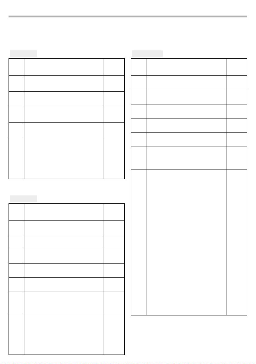
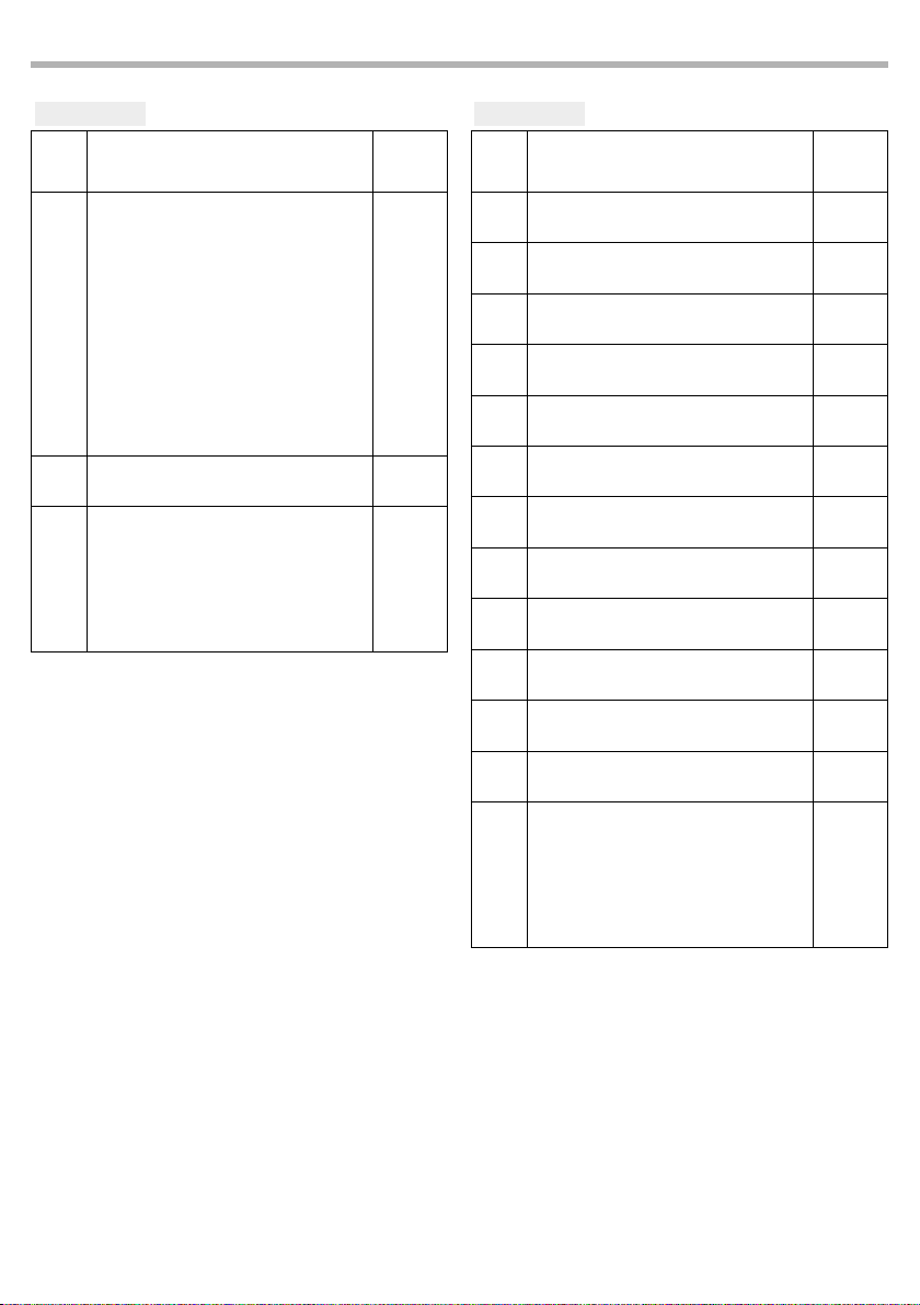
Le tabelle a pagina 15, 16 e 17 indicano le modalità operative e i relativi valori DMX. Come interfaccia DMX,
l'unità i connettori XLR a poli.
3.8 INDIRIZZAMENTO DMX
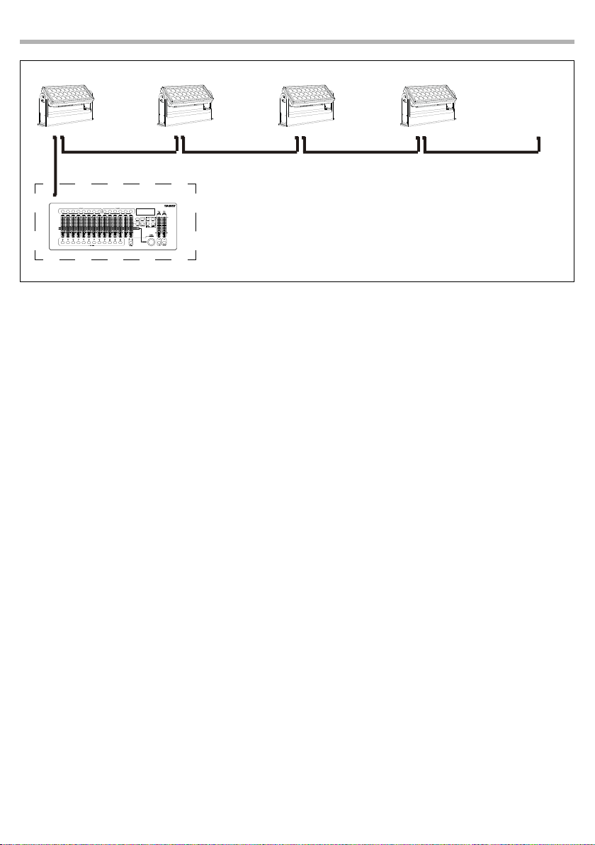
Per il funzionamento tramite un’unità di controllo della luce con protocollo DMX512, è suciente collegare ARCPOD27Q al controller. Il proiettore ha una congurazione del canale DMX a cui è possibile accedere
dal pannello di controllo. Per controllare ARCPOD27Q con un’unità di controllo della luce, è necessario
impostare l’indirizzo di avvio DMX per il primo canale DMX.
Se, ad esempio, sull’unità di controllo è previsto l’indirizzo 33 per controllare la funzione del primo canale
DMX, l’indirizzo iniziale 33 deve essere impostato su ARCPOD27Q. Le altre funzioni del pannello verranno
automaticamente assegnate ai seguenti indirizzi:
Number of
DMX chan-
nels
Start address
(example)
DMX Address
occupied
Next possible start
address for unit No. 1
Next possible start
address for unit No. 2
Next possible start
address for unit No. 3
5 33 33-37 38 43 48
7 33 33-39 40 47 54
10 33 33-42 43 53 63
13 33 33-45 46 59 72
17 33 33-49 50 67 84
Page 30
12
ARCPOD27Q
Indirizzo DMX: 38
Indirizzo DMX: 48
DMX512 Controller
Indirizzo DMX:53Indirizzo DMX: 43
. . . . . . . . . . . .
Fig.5 - Esempio di congurazione DMX a 5 canali
3.9 LED FREQUENCY
Selezionare questa funzione per regolare la frequenza del LED.
• Nel menù principale del DATAMASTER selezionare RDM.
• Premere il tasto ENTER per accedere al menù.Premere i tasti UP/DOWN per scorrere il menu, selezionare
LED Frequency, quindi premere il pulsante ENTER per accedere al menu successivo.
• Premere il pulsante UP/DOWN per selezionare una delle impostazioni disponibili: 600Hz, 1200Hz,
2000Hz, 4000Hz, 6000Hz, 25kH.
• Quindi selezionare ENTER per confermare.
• Premere ripetutamente il pulsante MENU per uscire dal menu.
3.10 SENSOR MENU
Per visualizzare la temperatura del dispositivo, procedere nel seguente modo.
• Nel menù principale del DATAMASTER selezionare RDM.
• Premere il tasto ENTER per accedere al menù.
• Premere i tasti UP/DOWN per scorrere il menu, selezionare Sensor Menu, quindi premere il pulsante INVIO
per accedere al menu successivo che mostrerà la temperatura del dispositivo.
• Premere ripetutamente il pulsante MENU per uscire dal menu.
3.11 SW VERSION
Per visualizzare la versione del software del dispositivo, procedere nel seguente modo.
• Selezionare RDM nel menu principale del DATAMASTER.
• Premere il tasto ENTER per accedere al sottomenu.
• Premere i tasti UP/DOWN per scorrere il menu, selezionare Sw Version, quindi premere il pulsante ENTER
per accedere al menu successivo che mostrerà la versione del software presente sul dispositivo.
• Premere ripetutamente il pulsante MENU per uscire dal menu..
3.12 UID
Per visualizzare l' UID del dispositivo, procedere nel seguente modo.
• In the main menu of the DATAMASTER select RDM.
• Press the ENTER button to access the main menu.
• Premere i tasti UP/DOWN per scorrere il menu, selezionare UID, quindi premere il pulsante INVIO per
accedere al menu successivo che mostrerà l' UID presente sul dispositivo..
• Premere ripetutamente il pulsante MENU per uscire dal menu.
Page 31

ARCPOD27Q
3.13 FACTORY DEFAULT
Per ripristinare il dispositivo predenito di fabbrica, procedere come segue:
• Nel menu principale del DATAMASTER selezionare RDM.
• Premere il pulsante ENTER per accedere al menu principale.
• Premere il pulsante SU/GIÙ per scorrere il menu, selezionare Factory Reload, quindi premere il tasto
ENTER per accedere al prossimo menù e scegliere l'opzione Yes o No.
• Premere ripetutamente il pulsante MENU per uscire dal menu e salvare le modiche apportate.
3.14 MANUAL COLOR
Per entrare in questa modalità procedere nel seguente modo:
• Nel menù principale del DATAMASTER selezionare Stand Alone.
• Premere il tasto ENTER per accedere al menù.
• Premere i tasti UP/DOWN per scorrere il menu, selezionare Manual Color, quindi premere il pulsante ENTER per accedere al menu successivo.
• Usare i tasti direzionali per impostare la miscelazione di colori desiderata (Red, Green, Blue, White) col
relativo valore (000-255). Premere il tasto ENTER per confermare.
• Premere ripetutamente il pulsante MENU per uscire dal menu.
NOTA: una volta impostato la miscelazione di colori desiderata con la modalità descritta, per cambiare ciò
in un secondo momento bisogna eettuare necessariamente il reset tramite la modalità Factory Reload.
3.15 EFFECTS
Per entrare in questa modalità procedere nel seguente modo:
• Nel menù principale del DATAMASTER selezionare Stand Alone.
• Premere il tasto ENTER per accedere al menù.
• Premere i tasti UP/DOWN per scorrere il menu, selezionare Eects, quindi premere il pulsante INVIO per
accedere al menu successivo.
• Usare i tasti direzionali per impostare l'eetto desiderato (Eect1, Eect2, Eect3, Eect4, Eect5) col relativo
valore (000-125). Premere il tasto ENTER per confermare.
• Premere ripetutamente il pulsante MENU per uscire dal menu.
NOTA: una volta impostato l'eetto desiderato con la modalità descritta, per cambiarlo in un secondo m
mento bisogna eettuare necessariamente il reset tramite la modalità Factory Reload.
13
NOTA: se precedentemente alla ricezione del segnale DMX, il proiettore si trova in modalità Blackout e se il
segnale DMX viene perso, il proiettore rimarrà acceso secondo l’ultimo valore DMX ricevuto. Se precedentemente alla ricezione del segnale DMX, il proiettore si trovava in modalità STATIC o AUTO e se il segnale
DMX viene perso, il proiettore tornerà allo STATIC o AUTO precedentemente impostato.
Page 32
14
3.16 COLLEGAMENTI DELLA LINEA DMX
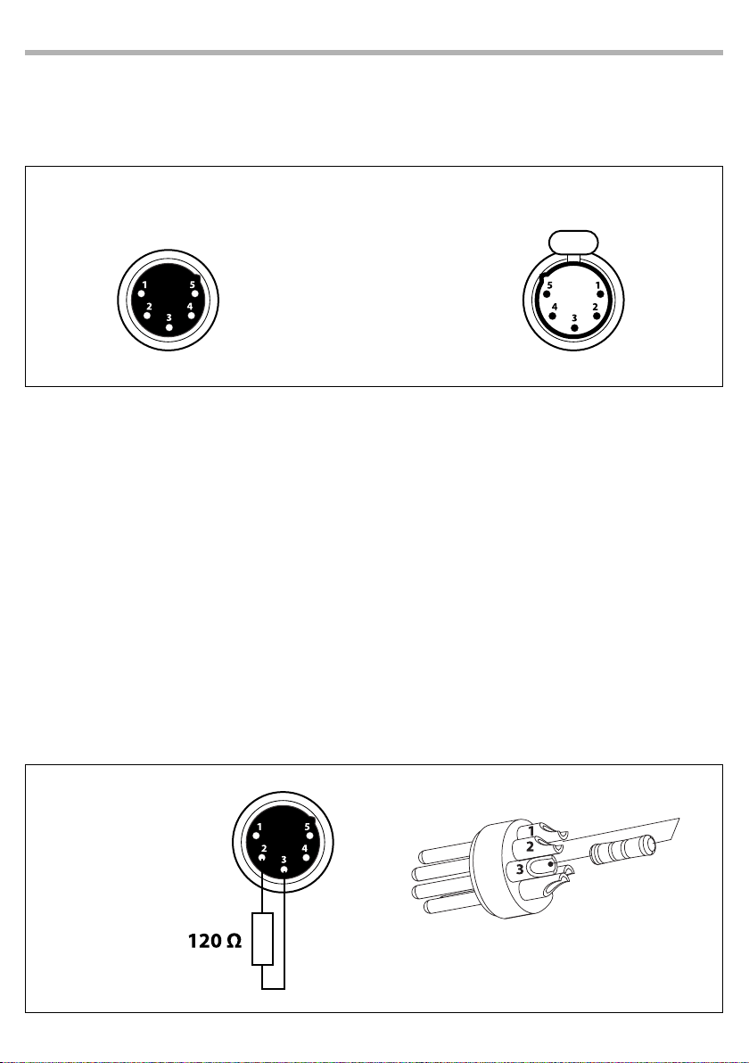
La connessione DMX è realizzata con connettori standard XLR. Utilizzare cavi schermati, 2 poli ritorti, con
impedenza 120Ω e bassa capacità.
Per il collegamento fare riferimento allo schema di connessione riportato di seguito:
ARCPOD27Q
DMX - INPUT
Spina XLR
Pin1 : Massa Schermo
Pin2 : - Negativo
Pin3 : + Positivo
Pin4 : N/C
Pin5 : N/C
ATTENZIONE
La parte schermata del cavo (calza) non deve mai essere collegata alla terra dell’impianto; ciò comporterebbe malfunzionamenti delle unità e dei controller.
Per passaggi lunghi può essere necessario l’inserimento di un amplicatore DMX.
In tal caso, è sconsigliato utilizzare nei collegamenti cavo bilanciato microfonico poiché non è in grado di
trasmettere in modo adabile i dati di controllo DMX.
• Collegare l’uscita DMX del controller con l’ingresso DMX della prima unità;
• Collegare, quindi, l’uscita DMX con l’ingresso DMX della successiva unità; l’uscita di quest’ultima con
l’ingresso di quella successiva e via dicendo nchè tutte le unità sono collegate formando una catena.
• Per installazioni in cui il cavo di segnale deve percorrere lunghe distanze è consigliato inserire sull’ultima unità una terminazione DMX.
3.17 COSTRUZIONE DEL TERMINATORE DMX
La terminazione evita la probabilità che il segnale DMX 512, una volta raggiunta la ne della linea stessa
venga riesso indietro lungo il cavo, provocando, in certe condizioni e lunghezze, la sua sovrapposizione
al segnale originale e la sua cancellazione.
La terminazione deve essere eettuata, sull’ultima unità della catena, con connettori XLR a 3/5 pin, saldando una resistenza di 120Ω (minimo 1/4W) tra i terminali 2 e 3, così come indicato in gura.
DMX - OUTPUT
Presa XLR
Fig.6
Esempio:
connettore XLR a 5 pin
Fig.7
Page 33
3.18 CANALI DMX
ARCPOD27Q
15
5 CANALI
MODE
FUNCTION DMX
5 Ch
RED
1
0~100% 000 - 255
GREEN
2
0~100% 000 - 255
BLUE
3
0~100% 000 - 255
WHITE
4
0~100% 000 - 255
DIMMER SPEED MODE
Preset dimmer speed from display menu
Dimmer speed mode o
5
Dimmer speed mode1 (fast speed)
Dimmer speed mode2 (middle speed)
Dimmer speed mode3 (slow speed)
7 CANALI
MODE
FUNCTION DMX
7 Ch
DIMMER
1
0~100% 000 - 255
RED
2
0~100% 000 - 255
GREEN
3
0~100% 000 - 255
BLUE
4
0~100% 000 - 255
WHITE
5
0~100% 000 - 255
STROBE
6
No function
Strobe Slow to Fast
DIMMER SPEED MODE
Preset dimmer speed from display menu
Dimmer speed mode o
7
Dimmer speed mode1 (fast speed)
Dimmer speed mode2 (middle speed)
Dimmer speed mode3 (slow speed)
Value
000-051
052-101
102-152
153-203
204-255
Value
000 - 010
011 - 255
000-051
052-101
102-152
153-203
204-255
10 CANALI
MODE
FUNCTION DMX
10 Ch
DIMMER
1
0~100% 000 - 255
RED
2
0~100% 000 - 255
GREEN
3
0~100% 000 - 255
BLUE
4
0~100% 000 - 255
WHITE
5
0~100% 000 - 255
STROBE
6
No function
Strobe Slow to Fast
COLOR MACRO
No Function
R 100%, G 0~100%, B 0 %
R 100%~0 %, G 100%, B 0 %
R 0 %, G 100%, B 0~100%
R 0 %, G 100~0 %, B 100%
R 0~100%, G 0 %, B 100%
R 100%, G 0 %, B 100~0 %
R 100%, G 0~100%, B 0~100%
R 100~0 %, G 100~0 %, B 100%
R 100%, G 100%, B 100%, W 100%
7
Color 1
Color 2
Color 3
Color 4
Color 5
Color 6
Color 7
Color 8
Color 9
Color 10
Color 11
Value
000 - 010
011 - 255
000 - 010
011 - 030
031 - 050
051 - 070
071 - 090
091 - 110
111 - 130
131 - 150
151 - 170
171 - 200
201 - 205
206 - 210
211 - 215
216 - 220
221 - 225
226 - 230
231 - 235
236 - 240
241 - 245
246 - 250
251 - 255
Page 34
16
ARCPOD27Q
10 CANALI
MODE
FUNCTION DMX
10 Ch
EFFECTS
NO Function
Eect 1
Eect 2
Eect 3
8
Eect4
Eect5 (Eects1- 4)
Eect 6
Eect 7
Eect 8
Eect 9 (Eects6- 8)
EFFECTS SPEED
9
Eects speed slow to fast 000 - 255
DIMMER SPEED MODE
Preset dimmer speed from display menu
Dimmer speed mode o
10
Dimmer speed mode 1 (fast speed)
Dimmer speed mode 2 (middle speed)
Dimmer speed mode 3 (slow speed)
Value
000-010
011-037
038-064
065-091
092-118
119-145
146-172
173-199
200-226
227-255
000 - 051
052 - 101
102 - 152
153 - 203
204 - 255
13 CANALI
MODE
FUNCTION DMX
13 Ch
RED 1
1
0~100% 000 - 255
GREEN 1
2
0~100% 000 - 255
BLUE 1
3
0~100% 000 - 255
WHITE 1
4
0~100% 000 - 255
RED 2
5
0~100% 000 - 255
GREEN 2
6
0~100% 000 - 255
BLUE 2
7
0~100% 000 - 255
WHITE 2
8
0~100% 000 - 255
RED 3
9
0~100% 000 - 255
GREEN 3
10
0~100% 000 - 255
BLUE 3
11
0~100% 000 - 255
WHITE 3
12
0~100% 000 - 255
DIMMER SPEED MODE
Preset dimmer speed from display menu
Dimmer speed mode o
13
Dimmer speed mode1 (fast speed)
Dimmer speed mode2 (middle speed)
Dimmer speed mode3 (slow speed)
Value
000-051
052-101
102-152
153-203
204-255
Page 35
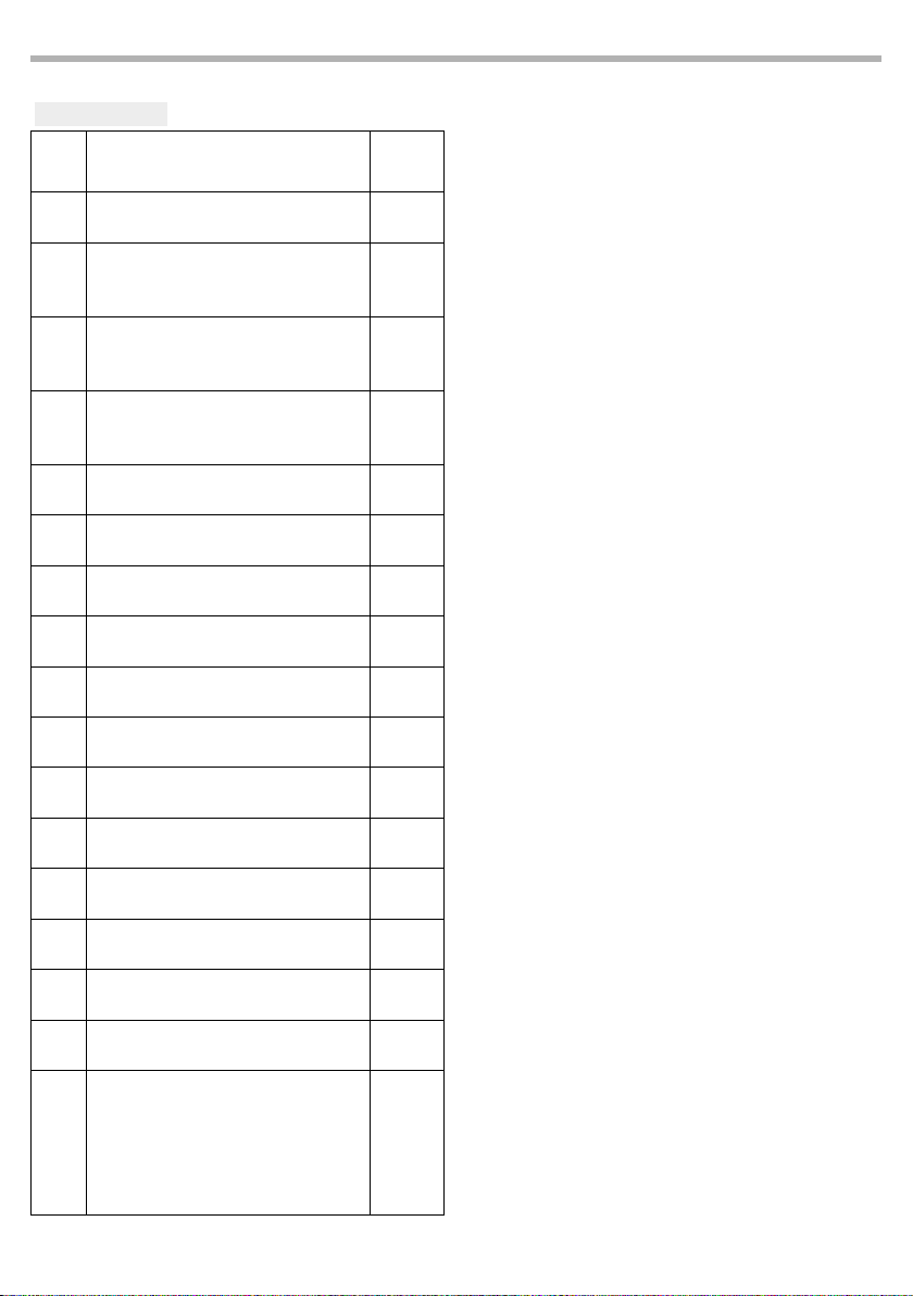
17 CHANNEL
MODE
FUNCTION DMX
17 Ch
DIMMER
1
0~100% 000 - 255
STROBE 1
2
No function
Strobe Slow to Fast
STROBE 2
3
No function
Strobe Slow to Fast
STROBE 3
4
No function
Strobe Slow to Fast
RED 1
5
0~100% 000 - 255
GREEN 1
6
0~100% 000 - 255
BLUE 1
7
0~100% 000 - 255
WHITE 1
8
0~100% 000 - 255
RED 2
9
0~100% 000 - 255
GREEN 2
10
0~100% 000 - 255
BLUE 2
11
0~100% 000 - 255
WHITE 2
12
0~100% 000 - 255
RED 3
13
0~100% 000 - 255
GREEN 3
14
0~100% 000 - 255
BLUE 3
15
0~100% 000 - 255
WHITE 3
16
0~100% 000 - 255
DIMMER SPEED MODE
Preset dimmer speed from display menu
Dimmer speed mode o
17
Dimmer speed mode1 (fast speed)
Dimmer speed mode2 (middle speed)
Dimmer speed mode3 (slow speed)
ARCPOD27Q
Value
000 - 010
011 - 255
000 - 010
011 - 255
000 - 010
011 - 255
000-051
052-101
102-152
153-203
204-255
17
Page 36

18
ARCPOD27Q
- 4 - MANUTENZIONE
4.1 MANUTENZIONE E PULIZIA DEL SISTEMA OTTICO
• Durante gli interventi, assicurarsi che l’area sotto il luogo di installazione sia libera da personale non
qualicato.
• Spegnere l’unità, scollegare il cavo di alimentazione ed aspettare nché l’unità non si sia rareddata.
• Tutte le viti utilizzate per l’installazione dell’unità e le sue parti dovrebbero essere assicurate saldamente e non dovrebbero essere corrose.
• Alloggiamenti, elementi di ssaggio e di installazione (sotto, truss, sospensioni) dovrebbero essere
totalmente esenti da qualsiasi deformazione.
• Quando una lente ottica è visibilmente danneggiata a causa di rotture o gra profondi, deve essere
sostituita.
• I cavi di alimentazione devono essere in condizione impeccabile e dovrebbero essere sostituiti immediatamente nel momento in cui anche un piccolo problema viene rilevato.
• Al ne di proteggere l’unità da surriscaldamento, le ventole di rareddamento (e nel caso) le aperture
di ventilazione, devono essere pulite mensilmente.
Per mantenere funzionalità e rendimento ottimali per lungo tempo è indispensabile eettuare una pulizia periodica delle parti soggette all’accumulo di polveri e grassi. La frequenza con la quale eettuare le
operazioni sotto indicate dipende da diversi fattori, quali la quantità di movimenti degli eetti e la qualità
dell’ambiente di lavoro (umidità dell’aria, presenza di polvere, salsedine, ecc.). Per rimuovere lo sporco dal
riettore, dalle lenti e dai ltri usare un panno morbido inumidito di un qualsiasi liquido detergente per
la pulizia del vetro. Annualmente si consiglia di sottoporre il proiettore a personale tecnico qualicato per
una manutenzione straordinaria consistente almeno nelle seguenti operazioni:
- Pulizia generale delle parti interne.
- Ripristino della lubricazione di tutte le parti soggette ad attrito tramite l’utilizzo di lubricanti
appropriati.
- Controllo visivo generale di componenti interni, cablaggio, parti meccaniche, ecc.
- Controlli elettrici, fotometrici e funzionali; eventuali riparazioni.
Attenzione: consigliamo che la pulizia interna sia eseguita da personale qualicato!
Page 37

ARCPOD27Q
4.2 RISOLUZIONE DEI PROBLEMI
Anomalie Possibili cause Controlli e rimedi
19
Il proiettore non illumina
Bassa intensità di luce generale
Il proiettore non è alimentato
Il proiettore non risponde al
DMX
• Mancanza di alimentazione di rete
• Dimmer impostato a 0
• Tutti i colori impostati a 0
• LED difettoso/i
• Scheda LED difettosa
• Lenti sporche
• Lente disallineata
• Mancanza di alimentazione di rete
• Cavo di alimentazione danneggiato
• Alimentatore interno difettoso
• Indirizzamento DMX errato
• Cavo di segnale DMX difettoso
• Rimbalzo segnale DMX
• Vericare la presenza della tensione alimentazione
• Incrementare i valori del canale dimmer
• Incrementare i valori dei canali colori
• Sostituire scheda LED
• Sostituire scheda LED
• Pulire il dispositivo regolarmente
• Installare il gruppo ottico correttamente
• Vericare la presenza della tensione alimentazione
• Controllare il cavo di alimentazione
• Sostituire l'alimentatore interno
• Controllare il pannello di controllo e l'indirizza-
mento delle unità
• Controllare il cavo di segnale DMX
• Installare una terminazione DMX come suggerito
Rivolgersi a un centro di assistenza tecnico autorizzato nel caso in cui il problema non sia riportato in
tabella.
Page 38

Page 39

Page 40

©2019 Music & Lights S.r.l.PROLIGHTS è un brand di proprietà della Music & Lights S.r.l. PROLIGHTS is a brand of Music & Lights S.r.l .company.
MUSIC & LIGHTS S.r.l. - Phone +39 0771 72190 - www.musiclights.it
 Loading...