

Page 1
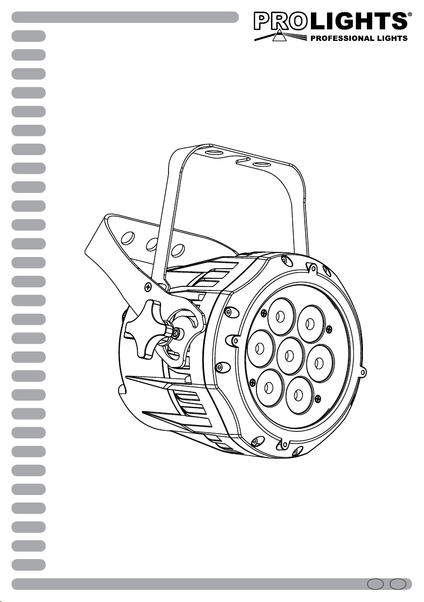
ARCLED7307HD
LED PROJECTOR
Manuale Utente
User Manual
ENIT
Page 2

Music & Lights S.r.l. si riserva ogni diritto di elaborazione in qualsiasi forma delle presenti istruzioni per l’uso.
Al ne di migliorare la qualità dei prodotti, la Music&Lights S.r.l. si riserva la facoltà di modicare, in
qualunque momento e senza preavviso, le speciche menzionate nel presente manuale di istruzioni.
Tutte le revisioni e gli aggiornamenti sono disponibili nella sezione 'Manuali' sul sito www.musiclights.it
La riproduzione - anche parziale - per propri scopi commerciali è vietata.
REV.001-04/13
Page 3
ARCLED7307HD
3
INDICE
Sicurezza
Avvertenze generali
Attenzioni e precauzioni per l’installazione
Informazioni generali
1 Introduzione
1. 1 Descrizione
1. 2 Speciche tecniche
1. 3 Elementi di comando e di collegamento
2 Installazione
2. 1 Montaggio
3 Funzioni e impostazioni
3. 1 Funzionamento
3. 2 Impostazione base
3. 3 Struttura menu
3. 4 Funzionamento in modalità automatica
3. 5 Modalità Master/Slave
3. 6 Collegamento
3. 7 Congurazione canali DMX
3. 8 Modalità DMX
3. 9 Impostazione dell'indirizzo di start
3. 10 Collegamenti della linea DMX
3. 11 Costruzione del terminatore DMX
3. 12 Tabella canali DMX
3. 13 Congurazione Static
3. 14 Editing programmi personalizzati
3. 15 Funzioni speciali
3. 16 Calibrazione
3. 17 Attivazione password
4
4
5
6
6
8
9
10
10
11
11
12
12
12
12
12
13
14
15
19
19
19
20
21
Contenuto dell'imballo:
4 Manutenzione
4. 1 Manutenzione e pulizia del sistema ottico
4. 2 Risoluzione dei problemi
5 Appendice
5. 1 Vista esplosa
Certificato di garanzia
• ARCLED7307HD
• Staa di ssaggio (2pz.)
• Cavo di sicurezza
• Manuale utente
22
22
23
Page 4
4
ATTENZIONE! Prima di effettuare qualsiasi operazione con l’unità, leggere con attenzione
questo manuale e conservarlo accuratamente per riferimenti futuri. Contiene informazioni
importanti riguardo l’installazione, l’uso e la manutenzione dell’unità.
ARCLED7307HD
SICUREZZA
Avvertenze generali
• I prodotti a cui questo manuale si riferisce sono conformi alle Direttive della Comunità Europea e pertanto recano la sigla .
• Il dispositivo funziona con pericolosa tensione di rete 230V~. Non intervenire mai al suo interno al di
fuori delle operazioni descritte nel presente manuale; esiste il pericolo di una scarica elettrica.
• È obbligatorio eettuare il collegamento ad un impianto di alimentazione dotato di un’eciente messa
a terra (apparecchio di Classe I secondo norma EN 60598-1). Si raccomanda, inoltre, di proteggere le
linee di alimentazione delle unità dai contatti indiretti e/o cortocircuiti verso massa tramite l’uso di
interruttori dierenziali opportunamente dimensionati.
• Le operazioni di collegamento alla rete di distribuzione dell’energia elettrica devono essere eettuate
da un installatore elettrico qualicato. Vericare che frequenza e tensione della rete corrispondono alla
frequenza ed alla tensione per cui l’unità è predisposta, indicate sulla targhetta dei dati elettrici.
• L’unità non per uso domestico, solo per uso professionale.
• Evitare di utilizzare l’unità:
- in luoghi soggetti a vibrazioni, o a possibili urti;
- in luoghi a temperatura superiore ai 45°C oppure a -20°C.
• Evitare che nell’unità penetrino liquidi inammabili, acqua o oggetti metallici.
• Non smontare e non apportare modiche all’unità.
• Tutti gli interventi devono essere sempre e solo eettuati da personale tecnico qualicato. Rivolgersi al
più vicino centro di assistenza tecnica autorizzato.
• Se si desidera eliminare il dispositivo denitivamente, consegnarlo
per lo smaltimento ad un’istituzione locale per il riciclaggio.
Attenzioni e precauzioni per l’installazione
• Se il dispositivo dovesse trovarsi ad operare in condizioni dierenti da quelle descritte nel presente
manuale, potrebbero vericarsi dei danni; in tal caso la garanzia verrebbe a decadere. Inoltre, ogni altra
operazione potrebbe provocare cortocircuiti, incendi, scosse elettriche, rotture etc.
• Prima di iniziare qualsiasi operazione di manutenzione o pulizia sull’unità togliere la tensione dalla rete
di alimentazione.
• È assolutamente necessario proteggere l’unità per mezzo di una fune di sicurezza. Nell’eseguire qualsiasi intervento attenersi scrupolosamente a tutte le normative (in materia di sicurezza) vigenti nel
paese di utilizzo.
• Installare l’unità in un luogo ben ventilato.
• Mantenere i materiali inammabili ad una distanza di sicurezza dall’unità.
• I ltri, le lenti o gli schermi ultravioletti se danneggiati possono limitare la loro ecienza.
• I LED devono essere sostituiti se danneggiati o termicamente deformati.
• Non guardare direttamente il fascio luminoso. Tenete presente che i veloci cambi di luce possono pro-
vocare attacchi d’epilessia presso persone fotosensibili o epilettiche.
• Non collegare il proiettore a un dimmer pack.
Page 5

ARCLED7307HD
INFORMAZIONI GENERALI
Spedizioni e reclami
Le merci sono vendute “franco nostra sede” e viaggiano sempre a rischio e pericolo del distributore/cliente. Eventuali avarie e danni dovranno essere contestati al vettore. Ogni reclamo per imballi manomessi
dovrà essere inoltrato entro 8 giorni dal ricevimento della merce.
Garanzie e resi
Il prodotto è coperto da garanzia in base alle vigenti normative. Sul sito www.musiclights.it è possibile
consultare il testo integrale delle “Condizioni Generali di Garanzia”. Si prega, dopo l’acquisto, di procedere
alla registrazione del prodotto sul sito www.musiclights.it. In alternativa il prodotto può essere registrato
compilando e inviando il modulo riportato alla ne del manuale. A tutti gli eetti la validità della garanzia
è avallata unicamente dalla presentazione del certicato di garanzia. Music & Lights constata tramite verica sui resi la difettosità dichiarata, correlata all’appropriato utilizzo, e l’eettiva validità della garanzia;
provvede quindi alla riparazione dei prodotti, declinando tuttavia ogni obbligo di risarcimento per danni
diretti o indiretti eventualmente derivanti dalla difettosità.
5
Page 6

6
ARCLED7307HD
- 1 - INTRODUZIONE
1.1 DESCRIZIONE
L’ ARCLED7307HD è stato disegnato per essere la versione “compact” del popolare fratello maggiore
ARCLED7314, che negli anni si è aermato essere un vero standard sul mercato.
Equipaggiato con 7x3W CREE LED RGB/FullColor e con un design lenti identico alla versione 7314,
ARCLED7307HD rappresenta una soluzione complementare ed adatta per orire un prodotto di
performance professionali anche in applicazioni con budget limitati.
Le dimensioni ipercompatte di ARCLED7307 ed il design il aluminio pressofuso e vetro temperato (IP66),
rendono questo proiettore un prodotto ideale per il Rental e versatile per qualsiasi applicazione in concerti,
illuminazione architetturale, luce d’accento e ere.
1.2 SPECIFICHE TECNICHE
Sorgente luminosa e ottica
• 7 x 3W CREE LED RGB/FC ad alta resa luminosa
• Lumen: 561
• Lux@2m: 1212@2m
• Peak intensity: 4837cd
• Diodi LED ad alta ecienza, con colori più vividi e minore assorbimento energetico delle lampade
tradizionali
• Sistema di sintesi colore: miscelazione RGB/FullColor (>16 milioni di colori) per possibilità cromatiche
illimitate
• Preset temperatura colore bianco: 3200K~10000K
• Ottiche installate: 16°
• Angolo di proiezione fascio: 17°
• Angolo di campo: 32°
• Durata media diodi LED: >50.000 ore
Funzionamento ed elettronica
• Diverse congurazioni DMX disponibili (3, 4, 5, 10, 13 canali) per controllo avanzato o semplicato
- 3 canali: RGB
- 3 canali: HSV
- 4 canali: RGB, dimmer
- 5 canali: RGB, dimmer, strobe
- 9 canali: RGB, dimmer, macro, strobe, auto programs, programs speed, dimmer curve, ID address
- 13 canali: RGB, RGB ne, dimmer, dimmer ne, macro, strobe, auto programs, programs speed, dimmer curve, ID address
• Valori dimmer e colori a risoluzione 16bit
• Interfaccia di controllo mediante display LED per esecuzione dei programmi automatici, scelta dei co-
lori statici, memorizzazione di show personalizzati, calibrazione preset colori
• Regolazione curva dimmer: 5 congurazioni selezionabili
• Modalità Master/Slave con più unità collegate
• Passaggio lineare “step less” dei valori sui canali DMX
• Frequenza dei diodi anti-icker (>400Hz)
• Silenziosità di funzionamento, proiettore privo di ventole e struttura disegnata per avere una dissipa-
zione a convezione
Page 7
ARCLED7307HD
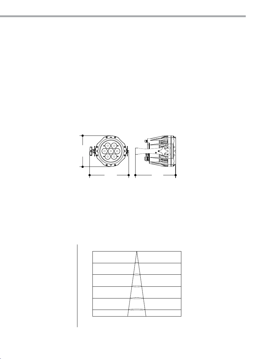
175
16°
Corpo e alimentazione
• Corpo in alluminio ad alta resistenza progettato per facilitare la dissipazione termica
• Pannello frontale: realizzato in vetro temperato
• Grado di isolamento: IP66 (IP) - IP54 (TZ)
• Bilanciamento temperatura e pressione attraverso valvole di sato GORE micro-forate
• Adattatori di alimentazione (shuko) e segnale (xlr-3p) inclusi
• Doppia staa per il ssaggio in sospensione e per il posizionamento del proiettore da terra
• Alimentazione: 100-240V 50/60Hz
• Condizioni di esercizio: -40/45°
• Output alimentazione per connessione di più unità in serie: no a 48 proiettori a 230V
• Consumo ad emissione massima: 27W
• Peso: 3,2 kg
• Dimensioni (LxAxP): 175x220x258 mm
220 228
7
Diagramma di luminosità
Fig.1
0m
2.0m
1212lx
4.0m
303lx
6.0m
134lx
8.0m
75lx
10.0m
Illuminance at a Distance
Lux Center Beam Angle: 16.7° Beam Width
Fig.2
0.58m
1.17m
1.76m
2.34m
2.93m48lx
Page 8
8
1.3 ELEMENTI DI COMANDO E DI COLLEGAMENTO
ARCLED7307HD
4 5
6 7
3
2
1
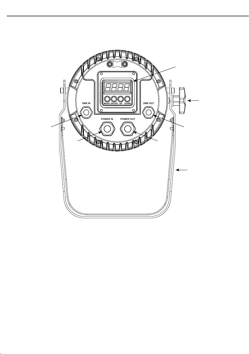
1. STAFFA DI MONTAGGIO
2. MANOPOLA DI FISSAGGIO per la staa di
montaggio
3. PANNELLO DI CONTROLLO con display e 4
pulsanti per accesso e gestione delle diverse
funzioni.
4. DMX IN (XLR a 3 poli):
1 = massa, 2 = DMX -, 3 = DMX +
5. DMX OUT (XLR a 3 poli):
1= massa, 2 = DMX -, 3 = DMX +
6. POWER IN (connettore di potenza Neutrik) per
il collegamento ad una presa di rete (100-240V
50/60Hz) tramite il cavo rete in dotazione.
7. POWER OUT (connettore di potenza Neutrik):
output alimentazione per connessione di più
unità in serie: no a 50 proiettori a 220V.
Fig.3
Page 9
ARCLED7307HD
9
- 2 - INSTALLAZIONE
2.1 MONTAGGIO
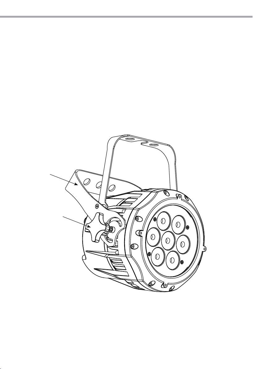
L’ ARCLED7307HD può essere collocato su un piano solido. Inoltre, grazie alle possibilità di ssaggio sulla
doppia staa (g.4), l’unità può essere montata anche a testa in giù, su una traversa. Per il ssaggio occorrono dei supporti robusti per il montaggio. L’area di collocazione deve avere una stabilità suciente e
supportare almeno 10 volte il peso dell’unità.
Inoltre assicurarsi di rispettare tutte le avvertenze in materia di sicurezza.
• Fissare il proiettore attraverso l’apposita staa (1) ad una collocazione idonea.
• È assolutamente necessario assicurare il proiettore contro la caduta utilizzando un cavo di sicurezza: in
particolare collegare il cavo in un punto adatto in modo che la caduta del proiettore non possa superare i 20 cm.
• Orientare il proiettore intervenendo, se necessario, sulla manopola della staa di montaggio (2).
1
2
Fig.4
Page 10
10
ARCLED7307HD
- 3 - FUNZIONI E IMPOSTAZIONI
3.1 FUNZIONAMENTO
Per accendere l’ ARCLED7307HD, inserire la spina del cavo di alimentazione in una presa di rete (100-240V
50/60Hz). L’unità può essere comandata da un unità DMX di comando luce oppure svolgere autonomamente il suo programma. Per spegnere l’ ARCLED7307HD, staccare la spina dalla presa di rete. Per maggiore comodità è consigliabile collegare l’unità con una presa comandata da un interruttore.
3.2 IMPOSTAZIONE BASE
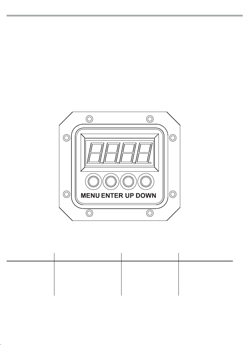
Il proiettore ARCLED7307HD dispone di un LED display e 4 pulsanti per accesso alle funzioni del pannello
di controllo (g.5).
Fig.5
MENU ENTER UP DOWN
Per scorrere il menu
principale o tornare ad
una opzione del menu
precedente
Per entrare nel menu selezionato o
confermare il valore attuale della
funzione o l'opzione all'interno di
un menu
Per scorrere attraverso le
diverse funzioni in ordine
discendente o aumentare il
valore della funzione stessa
Per scorrere attraverso le
diverse funzioni in ordine
ascendente o diminuire il
valore della funzione stessa
Page 11
3.3 STRUTTURA MENU
STAT
AUTO
RUN dMX / SLAVE
dMX d.(001-512)
PERS TOUR / TR16 / ARC.1 / AR1.d / AR1.S / HSV
EDIT PR.01 ÷ PR.10
SET
CAL
(Password:
UP-DOWN
UP-DOWN)
KEY ON/OFF
ARCLED7307HD
RED R.(000-255)
GREN G.(000-255)
BLUE b.(000-255)
STRB S.(0-20)
AT.01 ÷ AT.10
PR.01 ÷ PR.10
SC.01
...
SC.30
UPLd **** SEND OK
REST **** REST OK
COLO OFF/ RGBw / UC
dIMX DIM4 / DIM1 / DIM2 / DIM3 / OFF
CURV OFF / CV1 / CV2 / CV3
DERR SAVE/ BLAK
SLCK OFF/ON
STRB SPEC/CLAS
CAL1 wT.01 ÷ wT.11
****
CAL2 RGBw
CALR **** OK
RED, GREN,
BLUE, STRB,
TIME, FADE
R.(000-255), G.(000-255),
b.(000-255), S.(0-20), T.(000-255),
11
F.(000-255)
R.(000-255)
G.(000-255)
b.(000-255)
R.(000-255)
G.(000-255)
b.(000-255)
3.4 FUNZIONAMENTO IN MODALITÀ AUTOMATICA
Se alla presa DMX non è presente alcun segnale di comando DMX, l’unità può svolgere il suo programma
Show autonomamente:
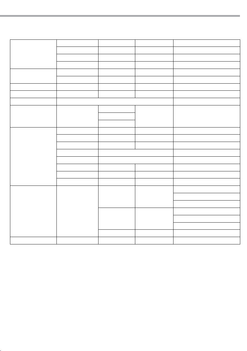
• Premere il tasto MENU no a quando sul display non appare [AUTO], quindi premere il tasto ENTER per
confermare la scelta.
• Premere il tasto UP/DOWN per scorrere al programma desiderato da 1 a 10 (AT.01 - AT.10 o PR.01 - PR.10).
L’unità entrerà in modalità automatica mandando in esecuzione il programma selezionato.
IMPORTANTE - I programmi AT.01 - AT.10 sono completamente pre-programmati e non possono subire esse-
re modicati. Invece, i programmi PR.01 - PR.10 possono essere modicati nella modalità EDIT.
NOTA - Nella modalità automatica l’unità è MASTER.
Page 12

12
ARCLED7307HD
3.5 MODALITÀ MASTER/SLAVE
Questa modalità consente di collegare in linea più unità ARCLED7307HD senza un controller. La prima
unità sarà impostata come master e le altre funzioneranno come slave con lo stesso eetto.
• Premere il tasto MENU no a quando sul display non appare [RUN], quindi premere il tasto ENTER per
confermare la scelta.
• Premere il tasto UP/DOWN e selezionare [SLAV] per impostare le unità come slave.
• Sull’unità MASTER selezionare il programma desiderato come indicato nel paragrafo 3.4
• Servirsi dei connettori DMX dell’ARCLED7307HD e di un cavo XLR per formare una catena di unità.
In certe condizioni e lunghezze si consiglia di eettuare una terminazione come mostrato a pagina 14.
3.6 COLLEGAMENTO
Si possono collegare più unità anché tutte le unità secondarie abbiano lo stesso eetto luce dell’unità
principale (Master).
1. Collegare l’uscita DMX OUT dell’unità principale con l’ingresso DMX IN della prima unità secondaria
servendosi di un cavo XLR a 3 poli.
2. Collegare l’uscita DMX OUT della prima unità secondaria con l’ingresso DMX IN della seconda unità
secondaria ecc.
3.7 CONFIGURAZIONI CANALI DMX
L’ ARCLED7307HD dispone di 6 congurazioni dei canali DMX a cui si può accedere dal pannello di controllo.
• Premere il tasto MENU no a quando sul display non appare [PERS], quindi premere il tasto ENTER.
• Attraverso il tasto UP/DOWN selezionare la congurazione dei canali DMX che si desidera [TOUR - TR16 -
ARC.1 - AR1.d - AR1.s - HSV]
Le tabelle a pagina 15 indicano le modalità di funzionamento e i relativi valori DMX. Come interfaccia
DMX, l’unità possiede dei contatti XLR a 3 poli.
3.8 MODALITÀ DMX
• Per poter entrare nella modalità DMX; premere il tasto MENU no a quando sul display non appare
[RUN], quindi premere il tasto ENTER.
• Premere il tasto UP/DOWN e selezionare la modalità [DMX].
• Dal menu iniziale, per impostare il valore desiderato, entrare nella modalità [dMX] e selezionare il valore
desiderato [001-512]; tenere premuto per lo scorrimento veloce.
• Al termine dell’impostazione il valore verrà salvato automaticamente
NOTA - Quando il dispositivo opera nella modalità automatica la funzione [RUN] non è disponibile.
3.9 IMPOSTAZIONE DELL’INDIRIZZO DI START
Per poter comandare l’ ARCLED7307HD con un’unità di comando luce, occorre impostare l’indirizzo di
start DMX per il primo canale DMX. Se, per esempio, sull’unità di comando è previsto l’indirizzo 33 per
comandare la funzione del primo canale DMX, si deve impostare sull’ ARCLED7307HD l’indirizzo di start
33. Le altre funzioni del pannello saranno assegnate automaticamente agli indirizzi successivi. Segue un
esempio con indirizzo 33 di start e una congurazione a 13 canali DMX:
Numero
canali DMX
Indirizzo di
start (esempio)
Indirizzo DMX
occupati
Prossimo indirizzo di start
possibile per unità n°1
Prossimo indirizzo di start
possibile per unità n°2
Prossimo indirizzo di start
possibile per unità n°3
13 33 33-45 46 59 72
Page 13
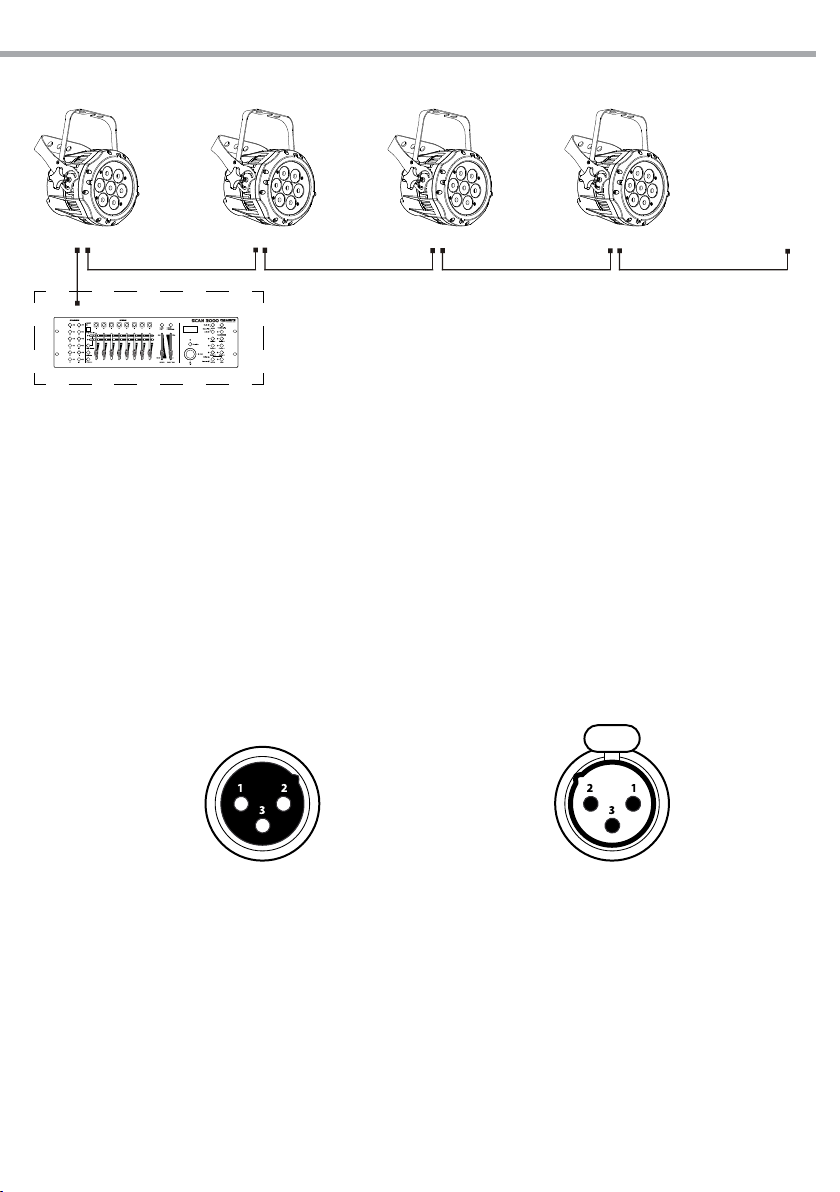
ARCLED7307HD
DMX Address: 33 DMX Address: 72DMX Address: 46 DMX Address: 59
DMX512 Controller
13
. . . . . . . . . . . .
Esempio di configurazione a 13 canali DMX (modalità TR16)
Fig.6
3.10 COLLEGAMENTI DELLA LINEA DMX
La connessione DMX è realizzata con connettori standard XLR. Utilizzare cavi schermati, 2 poli ritorti, con
impedenza 120Ω e bassa capacità.
Per il collegamento fare riferimento allo schema di connessione riportato di seguito:
DMX - INPUT
Spina XLR
Pin1 : Massa - Schermo
Pin2 : - Negativo
Pin3 : + Positivo
Fig.7
DMX - OUTPUT
Presa XLR
ATTENZIONE
La parte schermata del cavo (calza) non deve mai essere collegata alla terra dell’impianto; ciò comporterebbe malfunzionamenti delle unità e dei controller.
Per passaggi lunghi può essere necessario l’inserimento di un amplicatore DMX.
In tal caso, è sconsigliato utilizzare nei collegamenti cavo bilanciato microfonico poiché non è in grado di
trasmettere in modo adabile i dati di controllo DMX.
• Collegare l’uscita DMX del controller con l’ingresso DMX della prima unità;
• Collegare, quindi, l’uscita DMX con l’ingresso DMX della successiva unità; l’uscita di quest’ultima con
l’ingresso di quella successiva e via dicendo nchè tutte le unità sono collegate formando una catena.
• Per installazioni in cui il cavo di segnale deve percorrere lunghe distanze è consigliato inserire sull’ultima unità una terminazione DMX.
Page 14
14
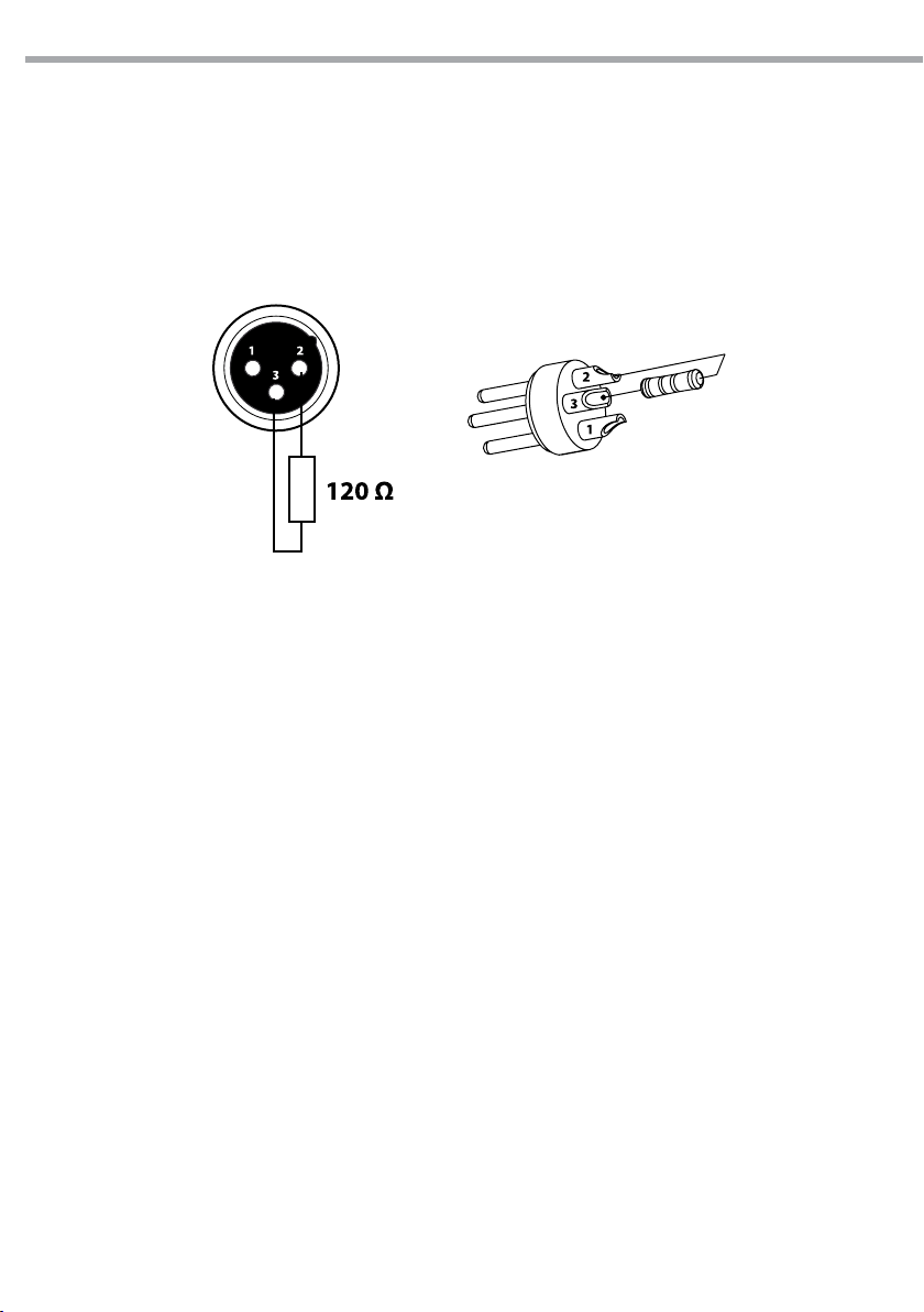
3.11 COSTRUZIONE DEL TERMINATORE DMX
La terminazione evita la probabilità che il segnale DMX 512, una volta raggiunta la ne della linea stessa
venga riesso indietro lungo il cavo, provocando, in certe condizioni e lunghezze, la sua sovrapposizione
al segnale originale e la sua cancellazione.
La terminazione deve essere eettuata, sull’ultima unità della catena, con connettori XLR a 3 pin, saldando
una resistenza di 120Ω (minimo 1/4W) tra i terminali 2 e 3, così come indicato in gura.
ARCLED7307HD
Esempio:
connettore XLR a 3 pin
Fig.8
Page 15

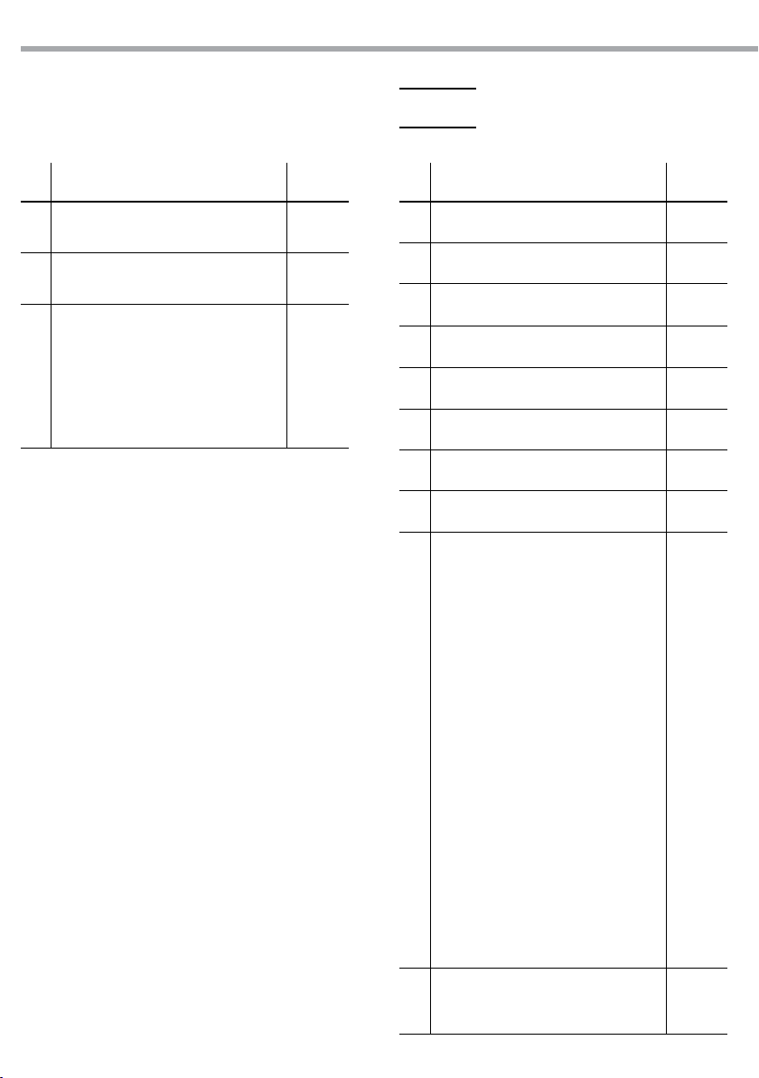
3.12 TABELLA CANALI DMX
TOUR
ARCLED7307HD
15
Ch Function in TOUR mode Value
MASTER DIMMER
1
000 - 100% 000 - 255
RED
2
(CH7 select CUSTOM 01-10, CH2 CONTROL TIME) 000 - 255
GREEN
3
(CH7 select CUSTOM 01-10, CH3 CONTROL FADE) 000 - 255
BLUE
4
000 - 100% 000 - 255
COLOR MACRO+WHITE BALANCE
No function
Red 100%/Green Up/Blue 0%
Red Down/Green 100%/Blue 0%
Red 0%/Green 100%/Blue Up
Red 0%/Green Down/Blue 100%
Red Up/Green 0%/Blue100%
Red 100%/Green 0%/Blue Down
Red 100%/Green Up/Blue Up
Red Down/Green Down/Blue 100%
All LEDs 100%
5
White 1: 3200K
White 2: 3400K
White 3: 4200K
White 4: 4900K
White 5: 5600K
White 6: 5900K
White 7: 6500K
White 8: 7200K
White 9: 8000K
White 10: 8500K
White 11: 10000K
SPECIAL STROBE
No strobe
Strobe (slow to fast)
No strobe
Lightning strobe (slow to fast)
6
No strobe
Random strobe (slow to fast)
CLASSIC STROBE
0Hz
1Hz
000 - 010
011 - 030
031 - 050
051 - 070
071 - 090
091 - 110
111 - 130
131 - 150
151 - 170
171 - 200
201 - 205
206 - 210
211 - 215
216 - 220
221 - 225
226 - 230
231 - 235
236 - 240
241 - 245
246 - 250
251 - 255
000 - 009
010 - 099
100 - 109
110 - 179
180 - 189
190 - 255
000 - 009
010 - 019
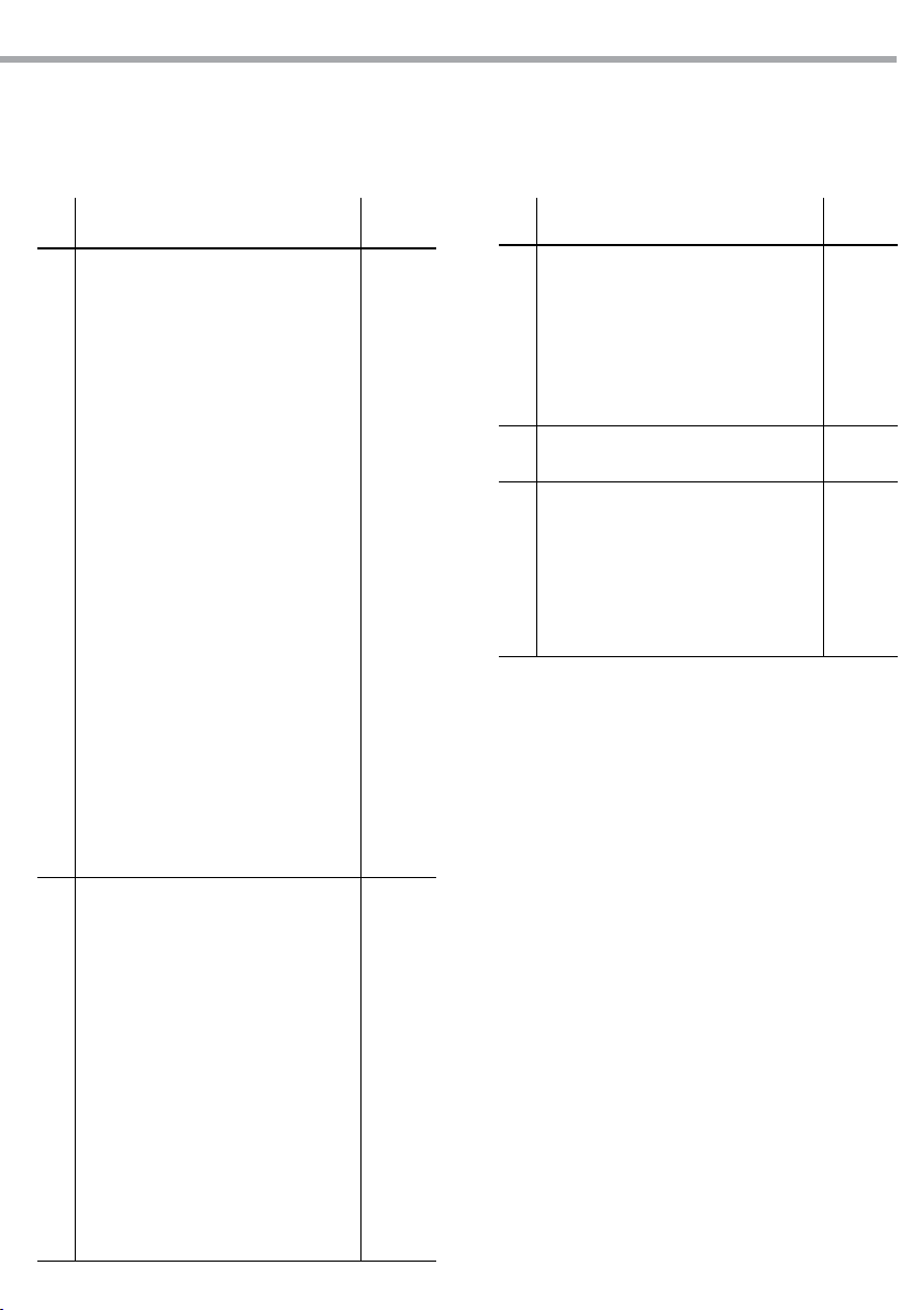
Ch Function in TOUR mode Value
6
7
2Hz
3Hz
4Hz
5Hz
6Hz
7Hz
8Hz
9Hz
10Hz
11Hz
12Hz
13Hz
14Hz
15Hz
16Hz
17Hz
18Hz
19Hz
20Hz
AUTO
No function
AUTO 01
AUTO 02
AUTO 03
AUTO 04
AUTO 05
AUTO 06
AUTO 07
AUTO 08
AUTO 09
AUTO 10
CUSTOM 01
CUSTOM 02
CUSTOM 03
CUSTOM 04
CUSTOM 05
CUSTOM 06
CUSTOM 07
CUSTOM 08
CUSTOM 09
020 - 029
030 - 039
040 - 049
050 - 059
060 - 069
070 - 079
080 - 089
090 - 099
100 - 109
110 - 119
120 - 129
130 - 139
140 - 149
150 - 159
160 - 169
170 - 179
180 - 189
190 - 199
200 - 255
000 - 020
021 - 030
031 - 040
041 - 050
051 - 060
061 - 070
071 - 080
081 - 090
091 - 100
101 - 110
111 - 120
121 - 130
131 - 140
141 - 150
151 - 160
161 - 170
181 - 190
191 - 200
201 - 210
211 - 220
Page 16
16
ARCLED7307HD
TR16
Ch Function in TOUR mode Value
CUSTOM 10
7
No function
AUTO SPEED
8
Since the walking speed (slow to fast) 000 - 255
DIMMER SPEED
Return settings
Normal
9
DIM1
DIM2
DIM3
DIM4
221 - 220
221 - 255
000 - 009
010 - 029
030 - 069
070 - 129
130 - 189
190 - 255
Ch Function in TR16 mode Value
1 MASTER DIMMER 000 - 255
2 MASTER DIMMER FINE 000 - 255
RED
3
(CH11 select CUSTOM 01-10, CH3 CONTROL TIME) 000 - 255
RED FINE
4
(CH11 select CUSTOM 01-10, CH4 CONTROL FADE) 000 - 255
5 GREEN 000 - 255
6 GREEN FINE 000 - 255
7 BLUE 000 - 255
8 BLUE FINE 000 - 255
COLOR MACRO+WHITE BALANCE
No function
Red 100%/Green Up/Blue 0%
Red Down/Green 100%/Blue 0%
Red 0%/Green 100%/Blue Up
Red 0%/Green Down/Blue 100%
Red Up/Green 0%/Blue100%
Red 100%/Green 0%/Blue Down
Red 100%/Green Up/Blue Up
Red Down/Green Down/Blue 100%
All LEDs 100%
9
White 1: 3200K
White 2: 3400K
White 3: 4200K
White 4: 4900K
White 5: 5600K
White 6: 5900K
White 7: 6500K
White 8: 7200K
White 9: 8000K
White 10: 8500K
White 11: 10000K
SPECIAL STROBE
10
No strobe
Strobe (slow to fast)
000 - 010
011 - 030
031 - 050
051 - 070
071 - 090
091 - 110
111 - 130
131 - 150
151 - 170
171 - 200
201 - 205
206 - 210
211 - 215
216 - 220
221 - 225
226 - 230
231 - 235
236 - 240
241 - 245
246 - 250
251 - 255
000 - 009
010 - 099
Page 17
ARCLED7307HD
17
CH Function in TR16 mode Value
No strobe
Lightning strobe (slow to fast)
No strobe
Random strobe (slow to fast)
CLASSIC STROBE
0Hz
1Hz
2Hz
3Hz
4Hz
5Hz
6Hz
7Hz
10
8Hz
9Hz
10Hz
11Hz
12Hz
13Hz
14Hz
15Hz
16Hz
17Hz
18Hz
19Hz
20Hz
AUTO
No function
AUTO 01
AUTO 02
AUTO 03
AUTO 04
AUTO 05
AUTO 06
11
AUTO 07
AUTO 08
AUTO 09
AUTO 10
CUSTOM 01
CUSTOM 02
CUSTOM 03
CUSTOM 04
100 - 109
110 - 179
180 - 189
190 - 255
000 - 009
010 - 019
020 - 029
030 - 039
040 - 049
050 - 059
060 - 069
070 - 079
080 - 089
090 - 099
100 - 109
110 - 119
120 - 129
130 - 139
140 - 149
150 - 159
160 - 169
170 - 179
180 - 189
190 - 199
200 - 255
000 - 020
021 - 030
031 - 040
041 - 050
051 - 060
061 - 070
071 - 080
081 - 090
091 - 100
101 - 110
111 - 120
121 - 130
131 - 140
141 - 150
151 - 160
Ch Function in TR16 mode Value
CUSTOM 05
CUSTOM 06
CUSTOM 07
11
CUSTOM 08
CUSTOM 09
CUSTOM 10
No function
AUTO SPEED
12
Since the walking speed (slow to fast) 000 - 255
DIMMER SPEED
Return settings
Normal
13
DIM1
DIM2
DIM3
DIM4
161 - 170
181 - 190
191 - 200
201 - 210
211 - 220
221 - 220
221 - 255
000 - 009
010 - 029
030 - 069
070 - 129
130 - 189
190 - 255
Page 18
18
ARCLED7307HD
ARC.1
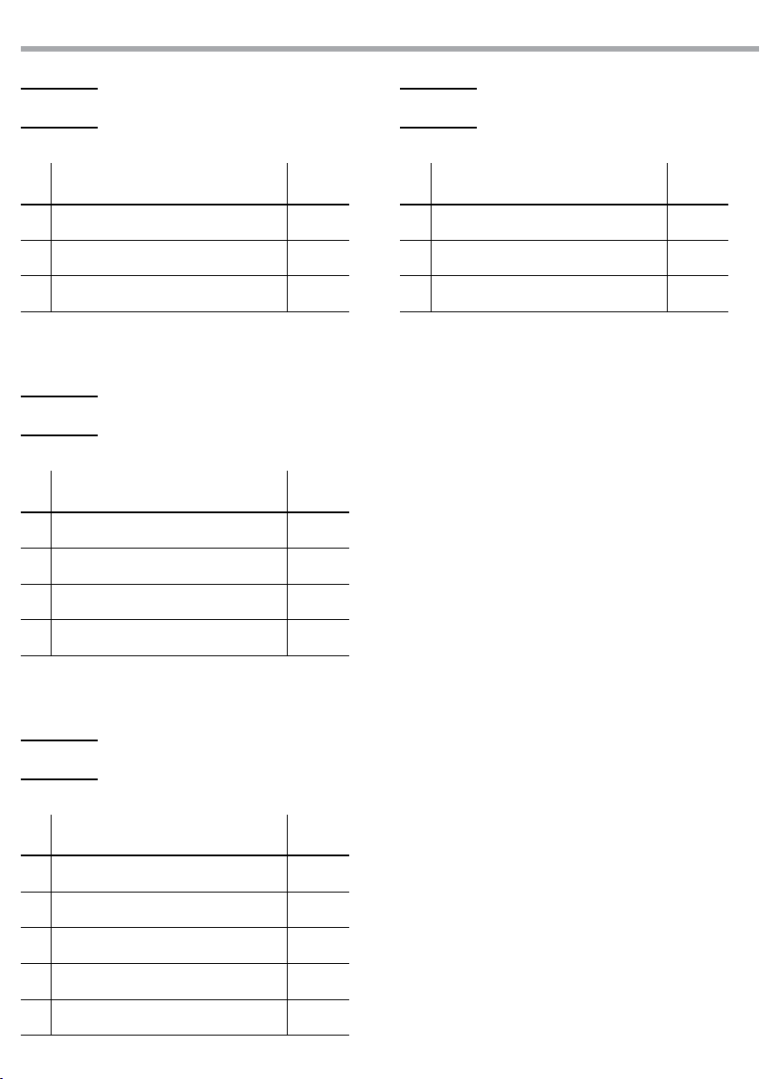
CH Function in ARC.1 Value
1 RED 0 - 100% 000 - 255
2 GREEN 0 - 100% 000 - 255
3 BLUE 0 - 100% 000 - 255
AR1.d
CH Function in AR1.d Value
1 MASTER DIMMER 000 - 255
2 RED 0 - 100% 000 - 255
3 GREEN 0 - 100% 000 - 255
HSV
CH Function in HSV Value
1 HUE 0 - 100% 000 - 255
2 SATURATION 0 - 100% 000 - 255
3 VALUE 0 - 100% 000 - 255
4 BLUE 0 - 100% 000 - 255
AR1.S
CH Function in AR1.S Value
1 MASTER DIMMER 000 - 255
2 RED 0 - 100% 000 - 255
3 GREEN 0 - 100% 000 - 255
4 BLUE 0 - 100% 000 - 255
5 STROBE 000 - 255
Page 19

ARCLED7307HD
3.13 CONFIGURAZIONE STATIC
Per impostare il bilanciamento personalizzato del rosso, verde e blu.
• Premere il tasto MENU per entrare nel menu principale, quindi premere il tasto UP/DOWN no a quando sul display non appare [STAT], quindi premere il tasto ENTER.
• Selezionare il canale rosso, verde o blu (RED - GREN -BLUE) attraverso i tasti UP/DOWN.
• Per confermare premere il tasto ENTER.
• Impostare i valori (000 - 255), attraverso i tasti UP/DOWN.
• Inne, impostare il valore [STRB] tra (0 - 20) mediante i tasti UP/DOWN.
3.14 EDITING PROGRAMMI PERSONALIZZATI
Per eettuare le modiche dei programmi personalizzati procedere come segue:
• Premere il tasto MENU no a quando sul display non appare [EDIT], quindi premere il tasto ENTER per
confermare la scelta.
• Premere il tasto UP o DOWN per selezionare il programma da modicare da 1 a 10 [PR.01- PR.10].
• Per ogni programma è possibile modicare 30 scene, intervenendo sui valori del canale rosso [RED],
verde [GREN], blu [BLUE] modicando i valori della funzione strobo [STRB 00-20], time [TIME 000-255] e fade
[FADE 000-255].
• I valori (ad esempio 000 - 255) possono essere selezionati attraverso il tasto UP/DOWN.
3.15 FUNZIONI SPECIALI
• Premere il tasto MENU e selezionare la voce [SETTINGS]; per confermare premere il tasto ENTER.
È possibile accedere alle seguenti funzioni:
NOTA - Le impostazioni di fabbrica relative alla password di accesso corrispondono alla combinazione dei
tasti UP + DOWN + UP + DOWN. Premere ENTER per confermare.
19
UPLOAD
• Selezionando la funzione [UPLd] è possibile caricare i programmi personalizzati dalla unità corrente
Master alle unità Slave. Per eseguire il trasferimento è necessario inserire la password che risulta
essere la stessa per l’accesso principale.
RESET
Selezionando la funzione [REST] è possibile ripristinare i valori di default.
COLOR
Selezionando la funzione [COLO] è possibile attivare/disattivare le modalità calibratura colore.
- Quando [RGB TO W] è selezionato, su RGB =255, 255, 255 il colore è visualizzato come calibrato nella
modalità CALIB2 (RGB TO W). Quando [COLOR] è impostato su [OFF], su RGB =255, 255, 255 il colore
non può essere regolato e l’uscita mostrerà la massima potenza.
- Quando [UC] è selezionato, i colori sono regolati secondo un preset universale standard.
DIMMER
Selezionando la funzione [dIM] è possibile entrare nella modalità dimmer. In particolare, quando è impostato su [OFF], l’RGBWA e il MASTER DIMMER sono lineari. Dim1/2/3/4 rappresentano invece diversi
valori di velocità nella modalità non lineare; [DIM1] è il valore più veloce mentre [DIM4] il più lento.
NOTA - Le impostazioni di fabbrica sono su [DIM4].
Page 20
20
CURV
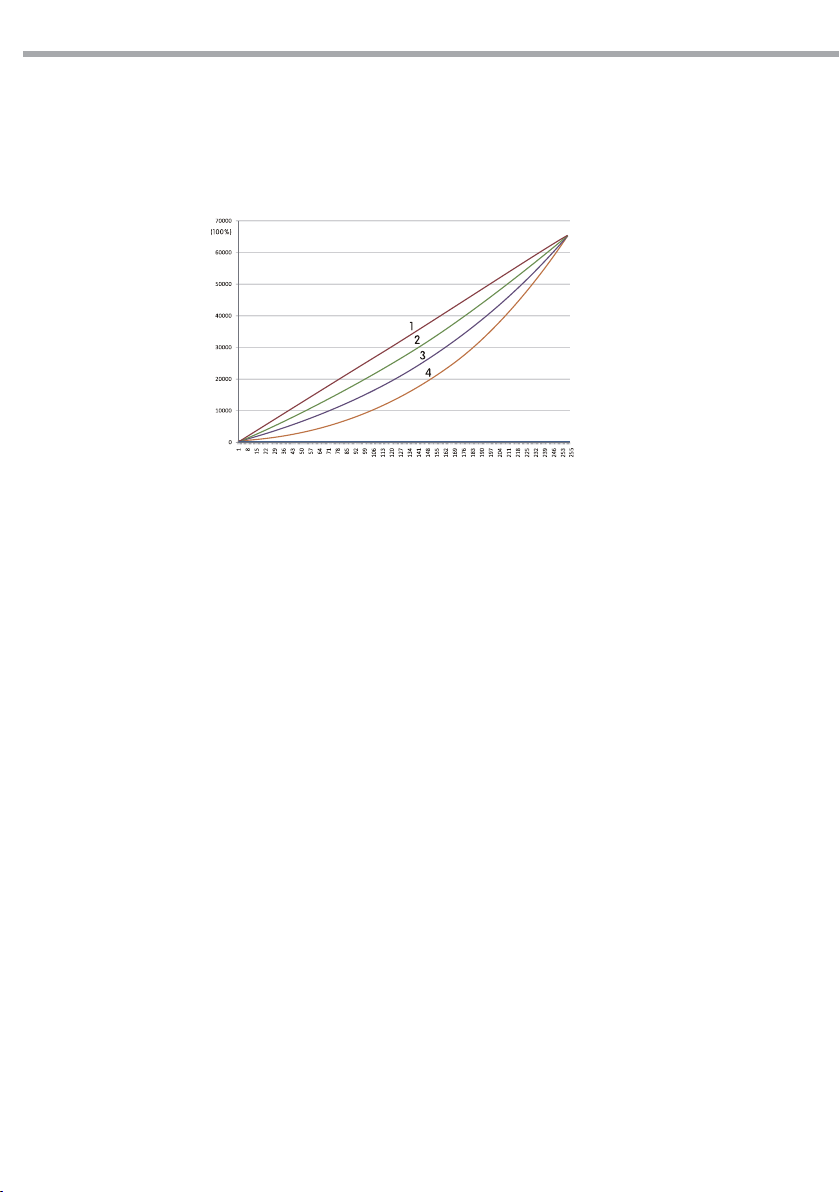
Selezionare la funzione [CURV], per regolare la forma della curva dimmer. Far riferimento al graco
riportato di seguito (g.9) per la caratteristica di ciascuna curva.
CURV dimming
DERR
Selezionare la funzione [DERR], per la gestione in caso di errore del segnale DMX.
- [SAVE] consente di salvare gli ultimi dati DMX in caso di errore del segnale DMX.
- [BLACK] consente di attivare la modalità blackout in caso di errore DMX.
ARCLED7307HD
1: OFF
2: CV1
3: CV3
4: CV4
Fig.9
SLCK
• Selezionando la funzione [SLCK] è possibile attivare o disattivare la password di accesso al menu di
impostazioni.
• Selezionare [ON] o [OFF] a seconda che si voglia, rispettivamente, abilitare o disabilitare la password.
Quando l’unità è impostata su ON, bisognerà immettere la password per accedere al menu impostazioni.
STRB
• Il proiettore ARCLED7307HD dispone di due dierenti impostazioni della strobo: CLAS strobo e SPEC
strobo. Tali impostazioni sono valide sono nelle seguenti congurazioni DMX: Tour, AR2.S e TR16.
3.16 CALIBRAZIONE
• Premere il tasto MENU e selezionare attraverso i tasti direzionali la voce [CAL]; inserire la password di
accesso corrispondente alla combinazione dei tasti UP + DOWN + UP + DOWN. Premere ENTER per
confermare.
IMPOSTAZIONI BIANCO
Per impostare il bilanciamento personalizzato della temperatura colore bianco:
• Premere il tasto MENU, quindi premere il tasto UP/DOWN no a quando sul display non appare
[CAL1], poi premere il tasto ENTER.
• Selezionare uno delle 11 impostazioni colore bianco pre-programmate (WHITE01 - WHITE11).
Page 21

ARCLED7307HD
• Le impostazioni possono essere modicate, intervenendo sui valori (000 - 255) relativi ai canali rosso,
verde e blu (Red - Green - Blue), attraverso i tasti UP/DOWN.
CALIBRAZIONE BIANCO
Per impostare il bilanciamento del bianco intervenendo sui parametri RGB:
• Premere il tasto MENU, quindi premere il tasto UP/DOWN no a quando sul display non appare
[CAL2], poi premere il tasto ENTER.
• Selezionare il canale rosso, verde, blu attraverso il tasto UP/DOWN.
• Per confermare premere il tasto ENTER
• Impostare i valori 000 - 255 attraverso i tasto UP/DOWN
Quando la nuova impostazione è attivata, l’unità di controllo DMX sceglierà RGB=255, 255, 255 il colore
bianco verrà fatto dagli attuali valori RGB nella modalità [CAL2]
3.17 ATTIVAZIONE PASSWORD
Per attivare/disattivare la password di accesso:
• Premere il tasto MENU e selezionare [KEY], quindi premere il tasto ENTER.
• Selezionare [ON] oppure [OFF] a seconda che si voglia, rispettivamente, attivare o disattivare la password
di accesso.
Quando l’unità è impostata su ON, dopo 30 secondi o al prossimo riavvio bisognerà immettere la password
per l’accesso menu di controllo.
NOTA - Le impostazioni di fabbrica relative alla password di accesso corrispondono alla combinazione dei
tasti UP+DOWN+UP+DOWN. Premere ENTER per confermare.
21
Page 22

22
ARCLED7307HD
- 4 - MANUTENZIONE
4.1 MANUTENZIONE E PULIZIA DEL SISTEMA OTTICO
• Durante gli interventi, assicurarsi che l’area sotto il luogo di installazione sia libera da personale non
qualicato.
• Spegnere l’unità, scollegare il cavo di alimentazione ed aspettare nché l’unità non si sia rareddata.
• Tutte le viti utilizzate per l’installazione dell’unità e le sue parti devono essere assicurate saldamente e
non devono essere corrose.
• Alloggiamenti, elementi di ssaggio e di installazione (sotto, truss, sospensioni) devono essere totalmente esenti da qualsiasi deformazione.
• I cavi di alimentazione devono essere in condizione impeccabile e devono essere sostituiti immediatamente nel momento in cui anche un piccolo problema viene rilevato.
• Si dovrebbe procedere, ad intervalli regolari, alla pulizia della parte frontale per asportare polvere,
fumo e altre particelle. Solo così, la luce può essere irradiata con la luminosità massima. Per la pulizia
usare un panno morbido, pulito e un detergente per vetri come si trovano in commercio. Quindi asciugare le parti delicatamente.
Attenzione: consigliamo che la pulizia interna sia eseguita da personale qualicato!
4.2 RISOLUZIONE DEI PROBLEMI
Anomalie Possibili cause Controlli e rimedi
Il proiettore non illumina
Bassa intensità di luce generale
Il proiettore non è alimentato
Il proiettore non risponde al
DMX
• Mancanza di alimentazione di rete
• Dimmer impostato a 0
• Tutti i colori impostati a 0
• LED difettoso/i
• Scheda LED difettosa
• Lenti sporche
• Lente disallineata
• Mancanza di alimentazione di rete
• Cavo di alimentazione danneggiato
• Alimentatore interno difettoso
• Indirizzamento DMX errato
• Cavo di segnale DMX difettoso
• Rimbalzo segnale DMX
• Vericare la presenza della tensione alimentazione
• Incrementare i valori del canale dimmer
• Incrementare i valori dei canali colori
• Sostituire scheda LED
• Sostituire scheda LED
• Pulire il dispositivo regolarmente
• Installare il gruppo ottico correttamente
• Vericare la presenza della tensione alimentazione
• Controllare il cavo di alimentazione
• Sostituire l'alimentatore interno
• Controllare il pannello di controllo e
l'indirizzamento delle unità
• Controllare il cavo di segnale DMX
• Installare una terminazione DMX come suggerito
Rivolgersi a un centro di assistenza tecnico autorizzato in caso di problema non riportato in tabella o che
non possono essere risolti mediante la procedura riportata in tabella.
Page 23
- 5 - APPENDICE
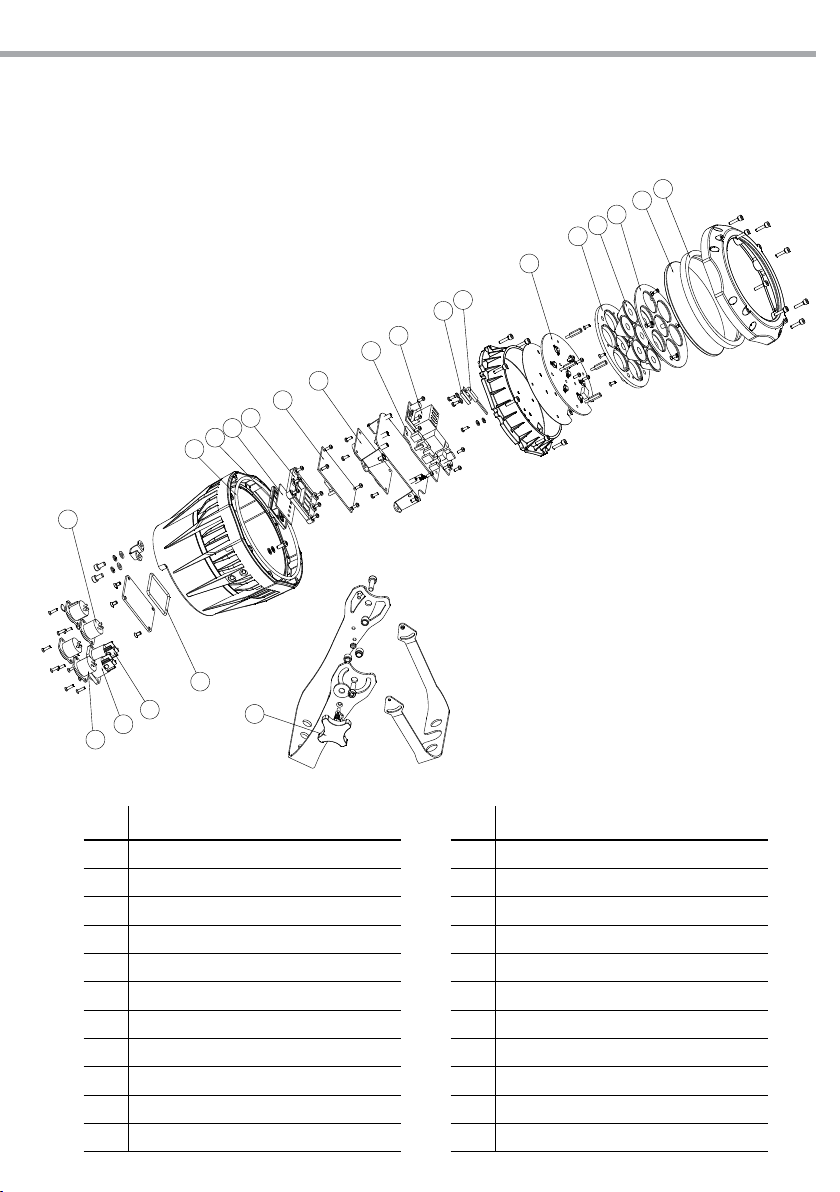
5.1 VISTA ESPLOSA
16
17
15
14
13
ARCLED7307HD
10
11
12
23
1
2
3
4
5
6
7
8
9
Fig.10
21
20
19
18
No ITEM
1 Rubber B
2 Glass
3 3 in 1 lens frame front cover
4
LED3 in 1 lens
5
3 in 1 lens frame back cover
6
LED board
7
Thermal switch
8
Thermal switch holder
9
Power supply
10
Adaptor PCB
11
Driver board
22
No ITEM
12 Display board
13
Button pressed plate
14
Display screen lens
15
Display board rubber
16
Rubber C
17
XLR 3 cores socket (male)
18
XLR 3 cores socket (female)
19
PS socket (male)
20
PS socket (male)
21
Rubber A
22
Adjusting stainless steel knob
Page 24

All rights reserved by Music & Lights S.r.l. No part of this instruction manual may be
reproduced in any form or by any means for any commercial use.
In order to improve the quality of products, Music&Lights S.r.l. reserves the right to modify the
characteristics stated in this instruction manual at any time and without prior notice.
All revisions and updates are available in the ‘manuals’ section on site www.musiclights.it
Page 25

ARCLED7307HD
1
TABLE OF CONTENTS
Safety
General instructions
Warnings and installation precautions
General information
1 Introduction
1. 1 Description
1. 2 Technical specications
1. 3 Operating elements and connections
2 Installation
2. 1 Mounting
3 Functions and settings
3. 1 Operation
3. 2 Basic
3. 3 Menu structure
3. 4 Operation in automatic mode
3. 5 Master/Slave mode
3. 6 Linking
3. 7 DMX conguration
3. 8 DMX mode
3. 9 DMX addressing
3. 10 Connection of the DMX line
3. 11 Construction of the DMX termination
3. 12 DMX control
3. 13 Static conguration
3. 14 Editing custom programs
3. 15 Special functions
3. 16 Calibration functions
3. 17 Activate the password
2
2
3
4
4
6
7
8
8
9
9
9
10
10
10
10
11
12
13
17
17
17
17
19
Packing content
4 Maintenance
4. 1 Maintenance and cleaning the unit
4. 2 Trouble shooting
5 Appendix
5. 1 Exploded view
Warranty
• ARCLED7307HD
• Mount bracket (2pc.)
• Safety cable
• User manual
20
20
21
Page 26
2
WARNING! Before carrying out any operations with the unit, carefully read this instruction
manual and keep it with cure for future reference. It contains important information about
the installation, usage and maintenance of the unit.
ARCLED7307HD
SAFETY
General instruction
• The products referred to in this manual conform to the European Community Directives and are therefore marked with .
• The unit is supplied with hazardous network voltage (230V~). Leave servicing to skilled personnel only.
Never make any modications on the unit not described in this instruction manual, otherwise you will
risk an electric shock.
• Connection must be made to a power supply system tted with ecient earthing (Class I appliance according to standard EN 60598-1). It is, moreover, recommended to protect the supply lines of the units
from indirect contact and/or shorting to earth by using appropriately sized residual current devices.
• The connection to the main network of electric distribution must be carried out by a qualied electrical
installer. Check that the main frequency and voltage correspond to those for which the unit is designed
as given on the electrical data label.
• This unit is not for home use, only professional applications.
• Never use the xture under the following conditions:
- in places subject to vibrations or bumps;
- in places with a temperature of over 45°C or -20°C.
• Make certain that no inammable liquids, water or metal objects enter the xture.
• Do not dismantle or modify the xture.
• All work must always be carried out by qualied technical personnel. Contact the nearest sales point for
an inspection or contact the manufacturer directly.
• If the unit is to be put out of operation denitively, take it to a local recycling
plant for a disposal which is not harmful to the environment.
Warnings and installation precautions
• If this device will be operated in any way dierent to the one described in this manual, it may suer
damage and the guarantee becomes void. Furthermore, any other operation may lead to dangers like
short circuit, burns, electric shock, etc.
• Before starting any maintenance work or cleaning the projector, cut o power from the main supply.
• Always additionally secure the projector with the safety rope. When carrying out any work, always com-
ply scrupulously with all the regulations (particularly regarding safety) currently in force in the country
in which the xture’s being used.
• Install the xture in a well ventilated place.
• Be sure that no ventilation slots on the product’s housing are blocked.
• Keep any inammable material at a safe distance from the xture.
• Shields, lenses or ultraviolet screens shall be changed if they have become damaged to such an extent
that their eectiveness is impaired.
• The lamp (LED) shall be changed if it has become damaged or thermally deformed.
• Never look directly at the light beam. Please note that fast changes in lighting, e. g. ashing light, may
trigger epileptic seizures in photosensitive persons or persons with epilepsy.
• Never connect the product to a dimmer pack.
Page 27

ARCLED7307HD
GENERAL INFORMATION
Shipments and claims
The goods are sold “ex works” and always travel at the risk and danger of the distributor. Eventual damage will have to be claimed to the freight forwarder. Any claim for broken packs will have to be forwarded
within 8 days from the reception of the goods.
Warranty and returns
The guarantee covers the xture in compliance with existing regulations. You can nd the full version of
the “General Guarantee Conditions” on our web site www.musiclights.it. Please remember to register the
piece of equipment soon after you purchase it, logging on www.musiclights.it. The product can be also
registered lling in and sending the form available on your guarantee certicate. For all purposes, the validity of the guarantee is endorsed solely on presentation of the guarantee certicate. Music & Lights will
verify the validity of the claim through examination of the defect in relation to proper use and the actual
validity of the guarantee. Music & Lights will eventually provide replacement or repair of the products declining, however, any obligation of compensation for direct or indirect damage resulting from faultiness.
3
Page 28

4
ARCLED7307HD
- 1 - INTRODUCTION
1.1 DESCRIPTION
ARCLED7307HD has been conceived to be the “compact” version of its popular big brother ARCLED7314,
which has become a real standard in the range of LED spotlight.
ARCLED7307 is equipped with 7x3W CREE RGB/FullColor LEDs combined with same optic design of 7314
version, representing a complementary xture of its bigger version and to introduce an high-quality tool
even in range of small lighters.
Its super-compact sizes and the construction made by die-cast aluminium housing with tempered glass
(IP66) makes ARCLED7307HD an essential product for the Rental stock, and useful for application in concerts, architectural lightings, accent lightings and corporate events.
1.2 TECHNICAL SPECIFICATIONS
Light source and optics
• 7 x 3W high-eciency CREE RGB/FC LEDs
• Lumen: 561
• Lux@2m: 1212@2m
• Peak intensity: 4837cd
• Energy-saving LEDs employed, with more vivid colours and lower power consumption than traditional
lamps
• Colour synthesis: RGB FullColor mixing (>16 million colours) for a limitless colour range
• White temperature presets: 3200K~10000K
• Installed optics: 16°
• Beam angle: 17°
• Field angle: 32°
• LEDs average life span: >50’000h
Electronics and features
• Several DMX selectable congurations (3, 4, 5, 10, 13 channels) for advanced or basic controlling
- 3 channels: RGB
- 3 channels: HSV
- 4 channels: RGB, dimmer
- 5 channels: RGB, dimmer, strobe
- 9 channels: RGB, dimmer, macro, strobe, auto programs, programs speed, dimmer curve, ID address
- 13 channels: RGB, RGBne, dimmer, dimmer ne, macro, strobe, auto programs, programs speed,
dimmer curve, ID address
• 16bit dimming and colour calibration
• LED display user interface for auto programs execution, static colour mode, creation of custom shows,
colour calibration presets
• 5 dierent dimming available curves
• Master/Slave mode for stand-alone operations
• Linear and “stepless” transition between DMX values
• Flicker-free operations (400Hz)
• Silent operations, due to natural cooling of the peculiar chassis and to absence of fans
Structure and power supply
• Sturdy die-cast aluminium body conceived for long-time durability and demanding applications
• Frontal tempered glass panel
Page 29
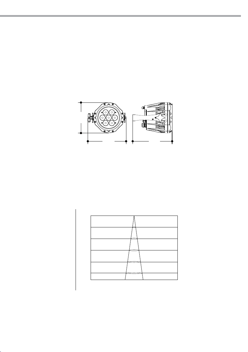
ARCLED7307HD
175
16°
Lux Center Beam Angle: 16.7° Beam Width
• Internal Protection: IP67 (IP) - IP54 (TZ)
• Pressure and temperature balance through GORE membrane vents
• Power (shuko) and data (xlr-3p) adapter cables included
• Double hanging bracket suitable for safe hanging and for oor positioning
• Power unit: 100-240V 50/60Hz
• Power output to link more units in a chain: up to 24 xtures at 230V
• Max power consumption: 27W
• Weight: 3,2 kg
• Dimensions (WxHxD): 175x220x258 mm
220 228
Fig.1
5
Photometric data
2.0m
4.0m
6.0m
8.0m
10.0m
Illuminance at a Distance
0m
1212lx
303lx
134lx
75lx
0.58m
1.17m
1.76m
2.34m
2.93m48lx
Fig.2
Page 30
6
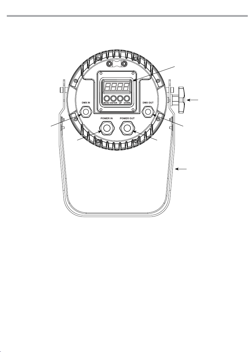
1.3 OPERATING ELEMENTS AND CONNECTIONS
ARCLED7307HD
4 5
6 7
3
2
1
1. MOUNTING BRACKET
2. LOCKING KNOB for the mounting bracket.
3. CONTROL PANEL with display and 4 button
used to access the control panel functions
and manage them.
4. DMX IN (3-pole XLR):
1 = ground, 2 = DMX -, 3 = DMX +
5. DMX OUT (3-pole XLR):
1= ground, 2 = DMX -, 3 = DMX +
6. POWER IN (Neutrik connector) for connection
to a socket (100-240V~/50-60Hz) via the
supplied mains cable.
7. POWER OUT (Neutrik connector): power
output for connection of multiple units in
series: 50 units may be connected in serie
(220V)
Fig.3
Page 31
ARCLED7307HD
7
- 2 - INSTALLATION
2.1 MOUNTING
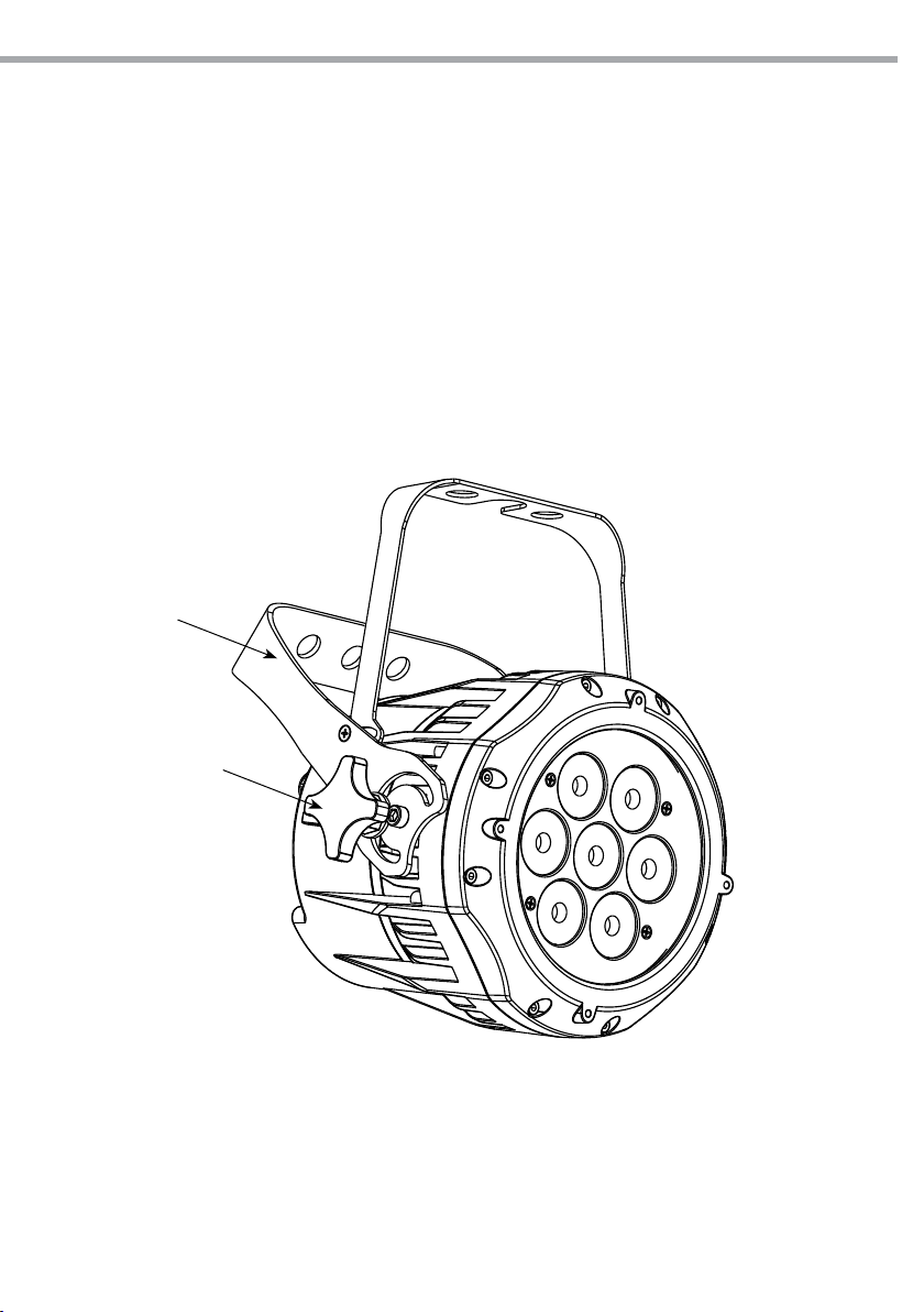
ARCLED7307HD may be set up on a solid and even surface. The unit can also be mounted upside down to
a cross arm. For xing, stable mounting clips are required. The mounting place must be of sucient stability and be able to support a weight of 10 times of the unit’s weight.
When carrying out any installation, always comply scrupulously with all the regulations (particularly regarding safety) currently in force in the country in which the xture’s being used.
• Install the projector at a suitable location by means of the mounting bracket (1).
• Always additionally secure the projector with the safety rope from falling down. For this purpose, fas-
ten the safety rope at a suitable position so that the maximum fall of the projector will be 20 cm.
• Adjust the projector and use the knob (2) to slightly release or tighten the locking mechanism of the
bracket if is necessary.
1
2
Fig.4
Page 32
8
ARCLED7307HD
- 3 - FUNCTIONS AND SETTINGS
3.1 OPERATION
Connect the supplied main cable to a socket (100-240 VAC-50/60 Hz). Then the unit is ready for operation
and can be operated via a DMX controller or it independently performs its show program in succession.
To switch o, disconnect the mains plug from the socket. For a more convenient operation it is recommended to connect the unit to a socket which can be switched on and o via a light switch.
3.2 BASIC
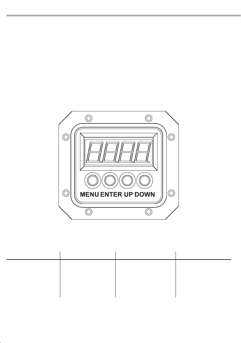
Access control panel functions using the four panel buttons located directly underneath the LED Display
(g.5).
MENU ENTER UP DOWN
Used to access the menu or
to return a previous menu
option
Used to select and store the
current menu or conrm the
current function value or
option within a menu
Fig.5
Navigates upwards through
the menu list and decreases
the numeric value when in a
function
Navigates downwards
through the menu list and
increases the numeric value
when in a function
Page 33
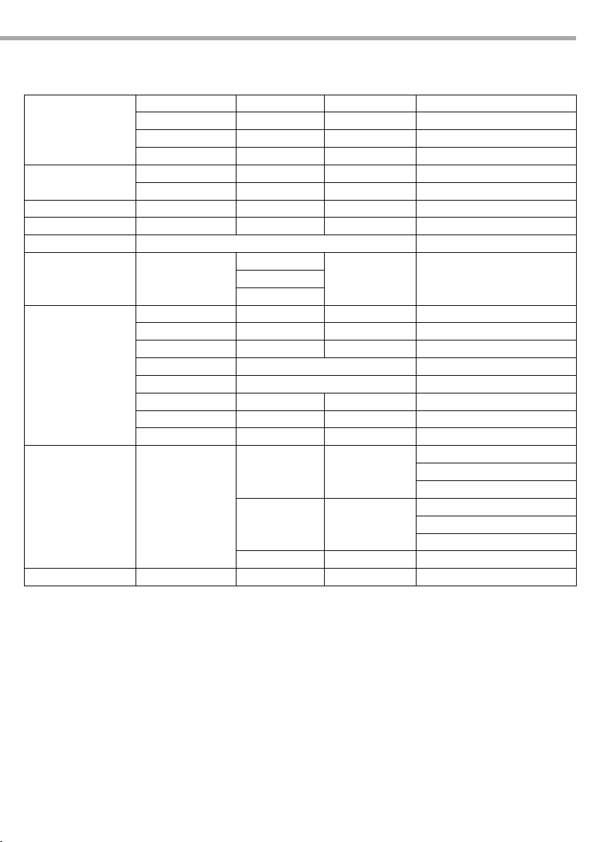
3.3 MENU STRUCTURE
STAT
AUTO
RUN dMX / SLAVE
dMX d.(001-512)
PERS TOUR / TR16 / ARC.1 / AR1.d / AR1.S / HSV
EDIT PR.01 ÷ PR.10
SET
CAL
(Password:
UP-DOWN
UP-DOWN)
KEY ON/OFF
ARCLED7307HD
RED R.(000-255)
GREN G.(000-255)
BLUE b.(000-255)
STRB S.(0-20)
AT.01 ÷ AT.10
PR.01 ÷ PR.10
SC.01
...
SC.30
UPLd **** SEND OK
REST **** REST OK
COLO OFF/ RGBw / UC
dIMX DIM4 / DIM1 / DIM2 / DIM3 / OFF
CURV OFF / CV1 / CV2 / CV3
DERR SAVE/ BLAK
SLCK OFF/ON
STRB SPEC/CLAS
CAL1 wT.01 ÷ wT.11
****
CAL2 RGBw
CALR **** OK
RED, GREN,
BLUE, STRB,
TIME, FADE
R.(000-255), G.(000-255),
b.(000-255), S.(0-20), T.(000-255),
9
F.(000-255)
R.(000-255)
G.(000-255)
b.(000-255)
R.(000-255)
G.(000-255)
b.(000-255)
3.4 OPERATION IN AUTOMATIC MODE
If no DMX control signal is present at the DMX INPUT, the unit independently runs through its show programme provided that the blackout mode is switched o:
• Press the button MENU so many times until the display shows [AUTO], then press the button ENTER.
• Press the button UP/DOWN to switch between the programs (AUTO 01 - AUTO10 o CUSTOM01 - CUSTOM10). The
unit will operate in automatic mode.
NOTE - Programs AUTO 01 - AUTO10 are fully pre-programmed and will not be altered by changes in EDIT
mode. Programs CUSTOM01 - CUSTOM10 are fully pre-programmed and can be edited in EDIT mode.
In automatic mode the unit will be set as Master.
Page 34

10
ARCLED7307HD
3.5 MASTER/SLAVE MODE
This mode will allow you to link up the units together without a controller. Choose a unit to function as the
Master. The unit must be the rst unit in line; other units will work as slave with the same eect.
• Press the button MENU so many times until the display shows [RUN], and press the button ENTER to
conrm.
• Press UP/DOWN to set the unit as [SLAVE].
• Select the desired program (see section 3.4).
• Use standard DMX cables to daisy chain your units together via the DMX connector on the rear of the
units. For longer cable runs we suggest a terminator at the last xture (see page 12).
3.6 LINKING
Several units may be interconnected in order to control all further slave units to the same eect of the
master unit.
1. Connect the DMX OUT of the master unit via 3 -pole XLR cable to the DMX IN of the rst slave unit.
2. Connect the DMX OUT of the rst slave unit to the DMX IN of the second slave unit, etc. until all units
are connected in a chain.
3.7 DMX CONFIGURATION
ARCLED7307HD is equipped with 6 DMX conguration.
• Press the button MENU so many times until shows [PERS], and press the button ENTER to conrm.
• Select the desired DMX conguration [TOUR - TR16 - ARC.1 - AR1.d - AR1.s - HSV ] through the buttons UP/
DOWN.
The tables on page 13 indicate the operating mode and DMX value. The ARCLED7307HD is equipped with
3 -pole XLR connections.
3.8 DMX MODE
• Press the button MENU so many times until the display shows [RUN], and press the button ENTER to
conrm.
• Press the buttons UP and DOWN to select [DMX] mode.
• Then enter the [ADDRESS] mode to set the ID address.
• Press the buttons UP and DOWN to select the desired value [001-512].
• After the setting value is automatically saved.
NOTE - When xtures are under Auto program operation, the [RUN] mode does no works.
3.9 DMX ADDRESSING
To able to operate the ARCLED7307HD with a light controller, adjust the DMX start address for the rst a
DMX channel. If e. g. address 33 on the controller is provided for controlling the function of the rst DMX
channel, adjust the start address 33 on the ARCLED7307HD. The other functions of the light eect panel
are then automatically assigned to the following addresses.
An example with the start address 33 is shown below:
Number of
DMX channels
Start address
(example)
DMX Address
occupied
Next possible start
address for unit No. 1
Next possible start
address for unit No. 2
Next possible start
address for unit No. 3
13 33 33-45 46 59 72
Page 35
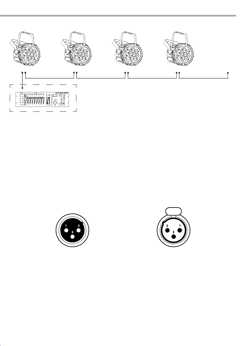
ARCLED7307HD
DMX Address: 33 DMX Address: 72DMX Address: 46 DMX Address: 59
DMX512 Controller
11
. . . . . . . . . . . .
Example 13 DMX channels configuration (TR16 mode)
Fig.6
3.10 CONNECTION OF THE DMX LINE
DMX connection employs standard XLR connectors. Use shielded pair-twisted cables with 120Ω impedance and low capacity.
The following diagram shows the connection mode:
DMX - INPUT
XLR plug
Pin1 : GND - Shield
Pin2 : - Negative
Pin3 : + Positive
Fig.5
DMX - OUTPUT
XLR socket
ATTENTION
The screened parts of the cable (sleeve) must never be connected to the system’s earth, as this would
cause faulty xture and controller operation.
Over long runs can be necessary to insert a DMX level matching amplier.
For those connections the use of balanced microphone cable is not recommended because it cannot
transmit control DMX data reliably.
• Connect the controller DMX input to the DMX output of the rst unit.
• Connect the DMX output to the DMX input of the following unit. Connect again the output to the input
of the following unit until all the units are connected in chain.
• When the signal cable has to run longer distance is recommended to insert a DMX termination on the
last unit.
Page 36
12
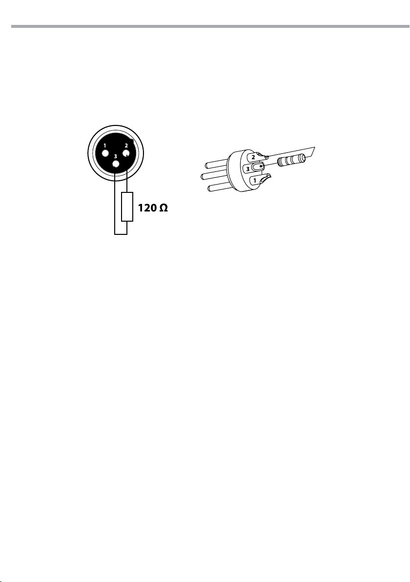
3.11 CONSTRUCTION OF THE DMX TERMINATION
The termination avoids the risk of DMX 512 signals being reected back along the cable when they reaches the end of the line: under certain conditions and with certain cable lengths, this could cause them to
cancel the original signals.
The termination is prepared by soldering a 120Ω 1/4 W resistor between pins 2 and 3 of the 5-pin male XLR
connector, as shown in gure.
ARCLED7307HD
Example:
3 pin XLR connector
Fig.6
Page 37
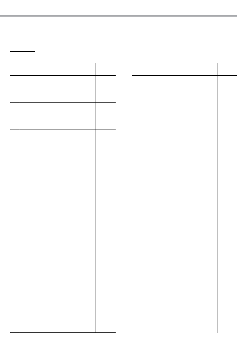
3.12 DMX CONTROL
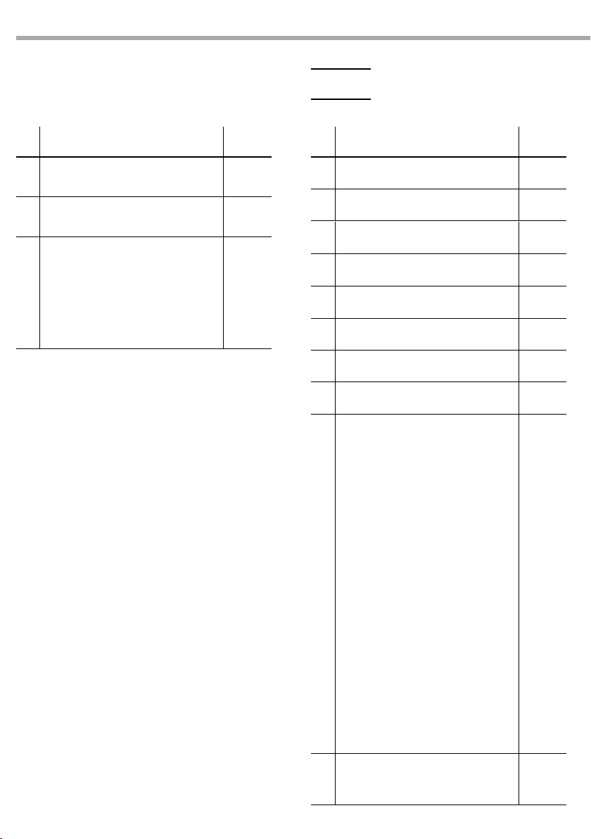
TOUR
ARCLED7307HD
13
Ch Function in TOUR mode Value
MASTER DIMMER
1
000 - 100% 000 - 255
RED
2
(CH7 select CUSTOM 01-10, CH2 CONTROL TIME) 000 - 255
GREEN
3
(CH7 select CUSTOM 01-10, CH3 CONTROL FADE) 000 - 255
BLUE
4
000 - 100% 000 - 255
COLOR MACRO+WHITE BALANCE
No function
Red 100%/Green Up/Blue 0%
Red Down/Green 100%/Blue 0%
Red 0%/Green 100%/Blue Up
Red 0%/Green Down/Blue 100%
Red Up/Green 0%/Blue100%
Red 100%/Green 0%/Blue Down
Red 100%/Green Up/Blue Up
Red Down/Green Down/Blue 100%
All LEDs 100%
5
White 1: 3200K
White 2: 3400K
White 3: 4200K
White 4: 4900K
White 5: 5600K
White 6: 5900K
White 7: 6500K
White 8: 7200K
White 9: 8000K
White 10: 8500K
White 11: 10000K
SPECIAL STROBE
No strobe
Strobe (slow to fast)
No strobe
Lightning strobe (slow to fast)
6
No strobe
Random strobe (slow to fast)
CLASSIC STROBE
0Hz
1Hz
000 - 010
011 - 030
031 - 050
051 - 070
071 - 090
091 - 110
111 - 130
131 - 150
151 - 170
171 - 200
201 - 205
206 - 210
211 - 215
216 - 220
221 - 225
226 - 230
231 - 235
236 - 240
241 - 245
246 - 250
251 - 255
000 - 009
010 - 099
100 - 109
110 - 179
180 - 189
190 - 255
000 - 009
010 - 019
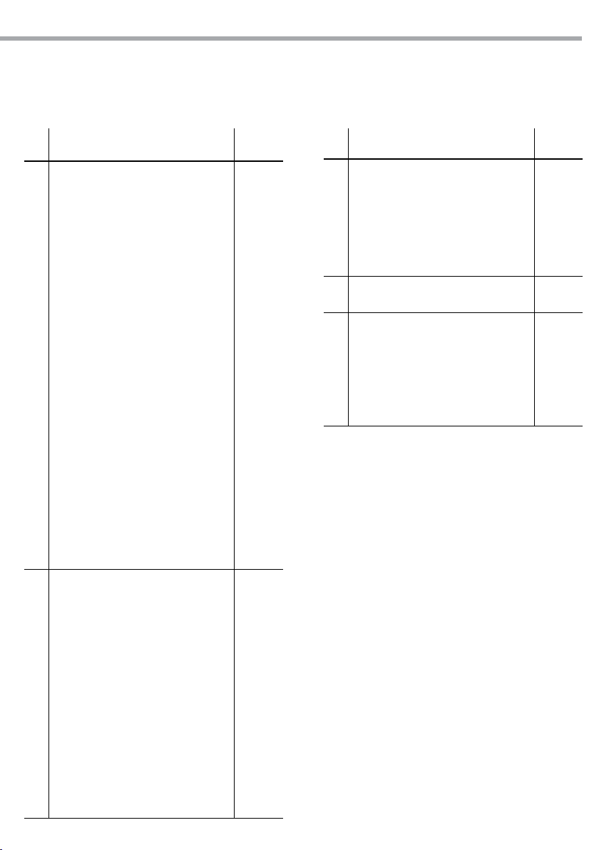
Ch Function in TOUR mode Value
6
7
2Hz
3Hz
4Hz
5Hz
6Hz
7Hz
8Hz
9Hz
10Hz
11Hz
12Hz
13Hz
14Hz
15Hz
16Hz
17Hz
18Hz
19Hz
20Hz
AUTO
No function
AUTO 01
AUTO 02
AUTO 03
AUTO 04
AUTO 05
AUTO 06
AUTO 07
AUTO 08
AUTO 09
AUTO 10
CUSTOM 01
CUSTOM 02
CUSTOM 03
CUSTOM 04
CUSTOM 05
CUSTOM 06
CUSTOM 07
CUSTOM 08
CUSTOM 09
020 - 029
030 - 039
040 - 049
050 - 059
060 - 069
070 - 079
080 - 089
090 - 099
100 - 109
110 - 119
120 - 129
130 - 139
140 - 149
150 - 159
160 - 169
170 - 179
180 - 189
190 - 199
200 - 255
000 - 020
021 - 030
031 - 040
041 - 050
051 - 060
061 - 070
071 - 080
081 - 090
091 - 100
101 - 110
111 - 120
121 - 130
131 - 140
141 - 150
151 - 160
161 - 170
181 - 190
191 - 200
201 - 210
211 - 220
Page 38
14
ARCLED7307HD
TR16
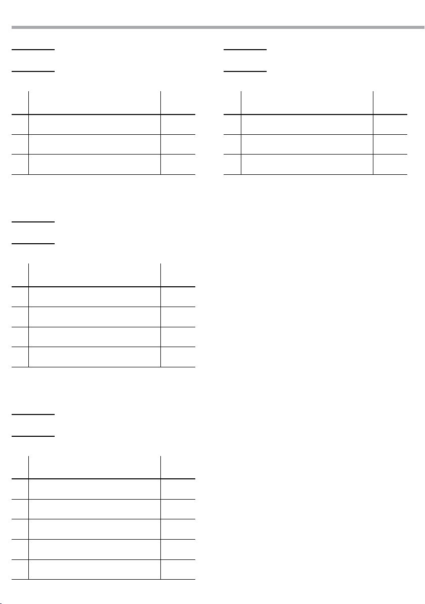
Ch Function in TOUR mode Value
CUSTOM 10
7
No function
AUTO SPEED
8
Since the walking speed (slow to fast) 000 - 255
DIMMER SPEED
Return settings
Normal
9
DIM1
DIM2
DIM3
DIM4
221 - 220
221 - 255
000 - 009
010 - 029
030 - 069
070 - 129
130 - 189
190 - 255
Ch Function in TR16 mode Value
1 MASTER DIMMER 000 - 255
2 MASTER DIMMER FINE 000 - 255
RED
3
(CH11 select CUSTOM 01-10, CH3 CONTROL TIME) 000 - 255
RED FINE
4
(CH11 select CUSTOM 01-10, CH4 CONTROL FADE) 000 - 255
5 GREEN 000 - 255
6 GREEN FINE 000 - 255
7 BLUE 000 - 255
8 BLUE FINE 000 - 255
COLOR MACRO+WHITE BALANCE
No function
Red 100%/Green Up/Blue 0%
Red Down/Green 100%/Blue 0%
Red 0%/Green 100%/Blue Up
Red 0%/Green Down/Blue 100%
Red Up/Green 0%/Blue100%
Red 100%/Green 0%/Blue Down
Red 100%/Green Up/Blue Up
Red Down/Green Down/Blue 100%
All LEDs 100%
9
White 1: 3200K
White 2: 3400K
White 3: 4200K
White 4: 4900K
White 5: 5600K
White 6: 5900K
White 7: 6500K
White 8: 7200K
White 9: 8000K
White 10: 8500K
White 11: 10000K
SPECIAL STROBE
10
No strobe
Strobe (slow to fast)
000 - 010
011 - 030
031 - 050
051 - 070
071 - 090
091 - 110
111 - 130
131 - 150
151 - 170
171 - 200
201 - 205
206 - 210
211 - 215
216 - 220
221 - 225
226 - 230
231 - 235
236 - 240
241 - 245
246 - 250
251 - 255
000 - 009
010 - 099
Page 39
ARCLED7307HD
15
CH Function in TR16 mode Value
No strobe
Lightning strobe (slow to fast)
No strobe
Random strobe (slow to fast)
CLASSIC STROBE
0Hz
1Hz
2Hz
3Hz
4Hz
5Hz
6Hz
7Hz
10
8Hz
9Hz
10Hz
11Hz
12Hz
13Hz
14Hz
15Hz
16Hz
17Hz
18Hz
19Hz
20Hz
AUTO
No function
AUTO 01
AUTO 02
AUTO 03
AUTO 04
AUTO 05
AUTO 06
11
AUTO 07
AUTO 08
AUTO 09
AUTO 10
CUSTOM 01
CUSTOM 02
CUSTOM 03
CUSTOM 04
100 - 109
110 - 179
180 - 189
190 - 255
000 - 009
010 - 019
020 - 029
030 - 039
040 - 049
050 - 059
060 - 069
070 - 079
080 - 089
090 - 099
100 - 109
110 - 119
120 - 129
130 - 139
140 - 149
150 - 159
160 - 169
170 - 179
180 - 189
190 - 199
200 - 255
000 - 020
021 - 030
031 - 040
041 - 050
051 - 060
061 - 070
071 - 080
081 - 090
091 - 100
101 - 110
111 - 120
121 - 130
131 - 140
141 - 150
151 - 160
Ch Function in TR16 mode Value
CUSTOM 05
CUSTOM 06
CUSTOM 07
11
CUSTOM 08
CUSTOM 09
CUSTOM 10
No function
AUTO SPEED
12
Since the walking speed (slow to fast) 000 - 255
DIMMER SPEED
Return settings
Normal
13
DIM1
DIM2
DIM3
DIM4
161 - 170
181 - 190
191 - 200
201 - 210
211 - 220
221 - 220
221 - 255
000 - 009
010 - 029
030 - 069
070 - 129
130 - 189
190 - 255
Page 40
16
ARCLED7307HD
ARC.1
CH Function in ARC.1 Value
1 RED 0 - 100% 000 - 255
2 GREEN 0 - 100% 000 - 255
3 BLUE 0 - 100% 000 - 255
AR1.d
CH Function in AR1.d Value
1 MASTER DIMMER 000 - 255
2 RED 0 - 100% 000 - 255
3 GREEN 0 - 100% 000 - 255
HSV
CH Function in HSV Value
1 HUE 0 - 100% 000 - 255
2 SATURATION 0 - 100% 000 - 255
3 VALUE 0 - 100% 000 - 255
4 BLUE 0 - 100% 000 - 255
AR1.S
CH Function in AR1.S Value
1 MASTER DIMMER 000 - 255
2 RED 0 - 100% 000 - 255
3 GREEN 0 - 100% 000 - 255
4 BLUE 0 - 100% 000 - 255
5 STROBE 2 000 - 255
Page 41

ARCLED7307HD
3.13 STATIC CONFIGURATION
To set the custom balance of red, blue and green:
• Press the button MENU, then press the button UP/DOWN so many times until the display shows [STAT].
Press the button ENTER to conrm.
• Select the color red, green or blue (RED - GREN -BLUE) through the buttons UP and DOWN and then press
the button ENTER.
• Set the value (000 - 255), through the buttons UP/DOWN.
• Set the value of the [STRB], (0 - 20) through the buttons UP/DOWN.
3.14 EDITING CUSTOM PROGRAMS
To set the custom balance of red, blue and green:
• Press the button MENU, then press the button UP/DOWN so many times until the display shows [EDIT ].
Press the button ENTER to conrm.
• Select the program PR.01 - PR.10.
• Each custom program has 30 steps that can be edited.
• Each step allows the creation of a scene using red (RED), green (GREEN), blue (BLUE), (STRB), (TIME) and (FADE).
• Set the value (000 - 255), through the buttons UP/DOWN.
3.15 SPECIAL FUNCTIONS
Press the button MENU and select through the directional buttons the [SETTINGS] mode; and press the but-
ton ENTER to conrm.
NOTE - The factory access password is UP + DOWN + UP + DOWN. Press ENTER to conrm the access.
It is possible to view to following functions:
17
UPLOAD
• Select [UPLd] to upload the custom programs from the current Master unit to the Slave units.
• In order to activate the upload function the password must be entered. Password is the same as the
main access password.
REST
• In order to reset custom modesto default values select [REST].
COLOR
• [COLO] is for activate/deactivate the color calibration functions.
- When [RGBW] is selected, on RGB =255, 255, 255 the color is displayed as calibrated in CAL2
(RGBW).
- When [COLOR] is set [OFF], on RGB =255, 255, 255 the RGB values are not adjusted and the output
is most powerful.
- When [UC] is selected, the RGB output adjusted to a standard preset universal color which
balances xtures from dierent generations.
DIMMER
• Enter [DIM] to select dimmer mode and dimmer speed. When dimmer is set to [OFF], the RGBW and
MASTER DIMMER are linear. The Dim1/2/3/4 are speed modes of the non linear dimmer, [DIM1] is the
faster, while [DIM4] is the slowest.
NOTE - The factory default setting is [DIM4].
Page 42

18
CURV
[CURV] allows the user to adjust the shape of the dimming curve. See the CURV chart to understand
more about actual dimming curves.
CURV dimming
DERR
Enter to [DERR] to control in case of DMX signal errors.
- [SAVE] saves the latest data DMX on error DMX signal.
- [BLACK] allows you to activate the mode on error DMX blackout.
ARCLED7307HD
1: OFF
2: CV1
3: CV3
4: CV4
Fig.9
SLCK
[SLCK] is used to lock the settings menu. When [SLCK] is set to ON the user must insert passcode (UP +
DOWN + UP + DOWN) in order to access the settings menu.
STRB
This xture allows for two dierent strobe personality settings, [CLAS] strobe or [SPEC] strobe. The [STRB]
settings are only valid in the DMX personalities TOUR, AR2.S and TR16.
3.16 CALIBRATION FUNCTION
Press the button MENU to enter the password conrmation, to enter the correct password
UP+DOWN+UP+DOWN button, press the MENU in the correct password will enter show submenu.
WHITE SETTING
Enter the [CAL] mode to select white color of dierent color temperature;
• Press the button MENU then press the button UP/DOWN so many times until show [CAL1]. Press the
button ENTER to conrm.
• There are 11 pre-programmed white colors (WHITE01 - WHITE11) can be edited by using red, green, and
blue (Red - Green - Blue).
• Set the value (000 - 255), through the buttons UP and DOWN.
Page 43

ARCLED7307HD
WHITE BALANCE
Enter the [CAL2] mode to adjust the RGB parameter to make dierent whites.
• Press the button MENU so many times until show [CAL2] and press the button ENTER to conrm.
• Select red, green or blue (RED - GREEN -BLUE), through the button UP/DOWN. Press the button
ENTER to conrm.
• Set the value 000 - 255, through the button UP/DOWN.
• When the new setting is activated, the DMX controller choose RGB=255, 255, 255 the write color will
be made by actual RGB values on the [CAL2].
3.17 ACTIVATE THE PASSWORD
Enter the KEY mode to select whether the access password is on or o.
• Press the button MENU so many times until show [KEY] and press the button ENTER to conrm.
• Select [ON] or [OFF].
When the xture is set as pass [ON], after 30 seconds or turn on the xture next time, the xture will need
an access password to enter the display menu control.
NOTE - The factory access password is UP + DOWN + UP + DOWN. Press ENTER to conrm the access.
19
Page 44

20
ARCLED7307HD
- 4 - MAINTENANCE
4.1 MAINTENANCE AND CLEANING THE UNIT
• Make sure the area below the installation place is free from unwanted persons during setup.
• Switch o the unit, unplug the main cable and wait until the unit has cooled down.
• All screws used for installing the device and any of its parts should be tightly fastened and should not
be corroded.
• Housings, xations and installation spots (ceiling, trusses, suspensions) should be totally free from any
deformation.
• The main cables must be in impeccable condition and should be replaced immediately even when a
small problem is detected.
• It is recommended to clean the front at regular intervals, from impurities caused by dust, smoke, or
other particles to ensure that the light is radiated at maximum brightness. For cleaning, disconnect the
main plug from the socket. Use a soft, clean cloth moistened with a mild detergent. Then carefully wipe
the part dry. For cleaning other housing parts use only a soft, clean cloth. Never use a liquid, it might
penetrate the unit and cause damage to it.
Warning: we strongly recommend internal cleaning to be carried out by qualied personnel!
4.2 TROUBLESHOOTING
Problems Possible causes Checks and remedies
Fixture does not light up
General low light intensity
Fixture does not power up
Fixture does not respond to DMX
• No mains supply
• Dimmer fader set to 0
• All color faders set to 0
• Faulty LED
• Faulty LED board
• Dirty lens assembly
• Misaligned lens assembly
• No power
• Loose or damaged power cord
• Faulty internal power supply
• Wrong DMX addressing
• Damaged DMX cables
• Bouncing signals
• Check the power supply voltage
• Increase the value of the dimmer channels
• Increase the value of the color channels
• Replace the LED board
• Replace the LED board
• Clean the xture regularly
• Install lens assembly properly
• Check for power on power outlet
• Check power cord
• Replace internal power supply
• Check control panel and unit addressing
• Check DMX cables
• Install terminator as suggested
Contact an authorized service center in case of technical problems or not reported in the table can not be
resolved by the procedure given in the table.
Page 45
- 5 - APPENDIX
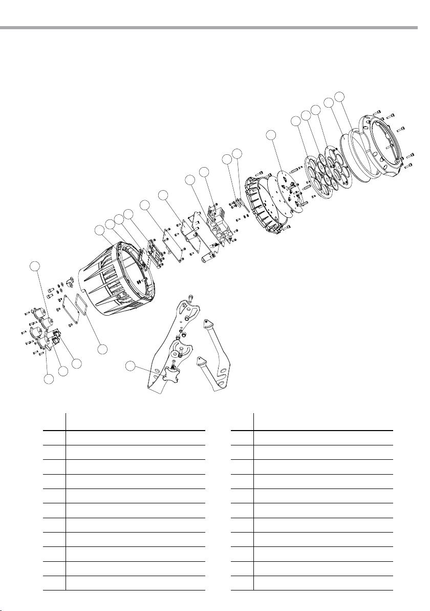
5.1 EXPLODED VIEW
17
16
15
14
13
ARCLED7307HD
10
11
12
21
1
2
3
4
5
6
7
8
9
Fig.10
21
20
19
18
No ITEM
1 Rubber B
2 Glass
3 3 in 1 lens frame front cover
4
LED3 in 1 lens
5
3 in 1 lens frame back cover
6
LED board
7
Thermal switch
8
Thermal switch holder
9
Power supply
10
Adaptor PCB
11
Driver board
22
No ITEM
12 Display board
13
Button pressed plate
14
Display screen lens
15
Display board rubber
16
Rubber C
17
XLR 3 cores socket (male)
18
XLR 3 cores socket (female)
19
PS socket (male)
20
PS socket (male)
21
Rubber A
22
Adjusting stainless steel knob
Page 46

Page 47
"
CERTIFICATO DI GARANZIA
GUARANTEE CERTIFICATE
Place Stamp Here
Arancare
Spett.le
Music&Lights S.r.l.
Via Appia Km 136.200
04020 Itri (LT) Italy
"
The guarantee covers the unit
in compliance with existing
regulations. You can find the
full version of the “General
Il prodotto è coperto da garanzia
in base alle vigenti normative.
Sul sito www.musiclights.it è
possibile consultare il testo
Guarantee Conditions” on our
web site www.musiclights.it.
integrale delle “Condizioni
Generali di Garanzia”.
Abstract
General Guarantee Conditions
Estratto dalle
Condizioni Generali di Garanzia
piece of equipment soon after you
• Please remember to register the
procedere alla registrazione del
• Si prega, dopo l’acquisto, di
purchase it, logging on
www.musiclights.it. The product
can be also registered lling in and
prodotto sul sito www.musiclights.it.
In alternativa il prodotto può essere
registrato compilando e inviando il
sending the form available on your
guarantee certicate.
modulo riportato sul retro.
• Sono esclusi i guasti causati da
• Defects caused by inexperience
imperizia e da uso non appropriato
and incorrect handling of the
equipment are excluded.
eective if the equipment has
been tampered.
• The guarantee will no longer be
• The guarantee makes no provision
dell’apparecchio.
qualora l’apparecchio sia stato
manomesso.
• La garanzia non ha più alcun eetto
sostituzione dell’apparecchio.
• La garanzia non prevede la
for the replacement of the
equipment.
esterne, le lampade, le manopole, gli
• Sono escluse dalla garanzia le parti
switches and removable parts are
• External parts, lamps, handles,
interruttori e le parti asportabili.
• Le spese di trasporto e i rischi
not included in the guarantee.
conseguenti sono a carico del
• Transport costs and subsequent
possessore dell’apparecchio.
risks are responsibility of the
owner of the equipment.
the guarantee is endorsed solely
• For all purposes, the validity of
garanzia è avallata unicamente
dalla presentazione del certicato di
garanzia.
• A tutti gli eetti la validità della
on presentation of the guarantee
certicate.
Page 48
FORM TO BE FILLED IN AND MAILED / CEDOLA DA COMPILARE E SPEDIRE FORM TO BE FILLED IN AND KEPT / CEDOLA DA COMPILARE E CONSERVARE
"
Purchased by / Acquistato da
Purchasing date
Data acquisto
del Rivenditore
ZIP CODE / C.A.P.
PROV.
CITY / CITTA’
ADDRESS / VIA N.
NAME / NOME
Dealer’s stamp
and signature
Timbro e rma
SURNAME / COGNOME
SERIAL N° / SERIE N°
MODEL / MODELLO
Purchased by / Acquistato da
Purchasing date
Data acquisto
del Rivenditore
ZIP CODE / C.A.P.
PROV.
CITY / CIT Tà
ADDRESS / VIA N.
NAME / NOME
Dealer’s stamp
and signature
Timbro e rma
SURNAME / COGNOME
SERIAL N° / SERIE N°
MODEL / MODELLO
Page 49

Page 50

Page 51

Page 52

©2013 Music & Lights S.r.l.PROLIGHTS è un brand di proprietà della Music & Lights S.r.l. PROLIGHTS is a brand of Music & Lights S.r.l .company.
Music & Lights S.r.l. entertainment technologies
Via Appia km 136,200 - 04020 Itri (LT) ITALY
tel. +39 0771 72190 fax +39 0771 721955
www.musiclights.it [email protected]
ISO 9001:2008
Certified Compa ny
 Loading...