

Page 1
2
1
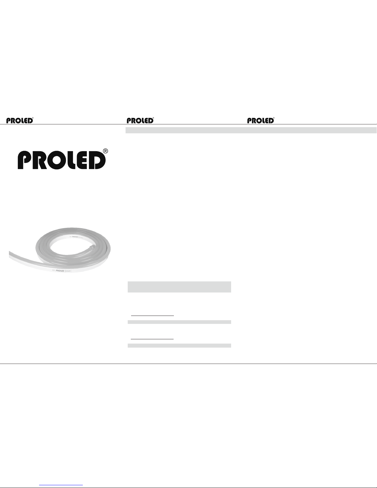
FLEX TUBE PRO MONO
WHITE / WA RM WH ITE / BLU E / GRE EN
WEISS / WA RM WE ISS / BLA U / GRÜ N
USER MANUAL
BEDIENUNGSANLEITUNG
1. Typ e / Typ: FLE X TUBE P RO MONO
2. In put vol tage / Ei ngang sspan nung: D C 24V
3. Po wer / Lei stung saufn ahme : 11 W /m
4. Di mensi on / Abme ssung en: 16 x 28 mm
5. LE D quant ity / Anz ahl: 60 L EDs/m tr
6. Mi n. cutt ing len gth / Min . Schni ttabs tand: 1 00mm (6 L EDs)
7. Ma x. runn ing len gth: 10 m trs for s ingle e nd feed
Län ge pro Ei nspei sung: 1 0 mtr bei e insei tiger E inspe isung
8. Li ght col or / Lich tfarb e: MONO
WHI TE / WARM WH ITE / BLU E / GREEN
WEI SS / WARM W EISS / B LAU / GRÜ N
9. Mi n. bent d iamet er / Min. B ieger adius : 120mm
Do no t twist t he ligh t . Nicht v erdre hen
10. P rotec tion ra te / Schu tzkla sse: IP 65
11. P rotec tion ra te for IP 65: All co nnect or join ts must b e conne cted
cor rectl y to achi eve IP6 5 ratin g.
Sch utzkl asse IP 65: Alle A nsch lüsse m üssen k orrek t ausge führt s ein
um di e Schut zklas se IP65 z u errei chen.
12. Can be cu t and ext ended . Kann ge schni tten un d erwei tert we rden
13. Worki ng ambi ent tem perat ure / : -20 °C - 45°C
Arbe its-U mgebu ngste mpera tur: -2 0°C - 45° C
14. Opera ting (b endin g) ambi ent tem perat ure: 0° C - 45°C
Bet riebs -Umge bungs tempe ratur ( Biege n): 0°C - 4 5°C
WARNIN G AN D CAUTI ON /
WARNUN GE N UND HIN WE ISE
WARN ING / WARN UNG
1. Befo re maki ng any cu ts, ins talla tion, m ainte nance o r conne ction , be sure t he main s is
dis conne cted!
Bit te vor de m Schne iden, M ontag e, Wartu ng oder V erbin dung si chers telle n, dass
Hau ptzul eitun g abgek lemmt i st !
2. NO TE: ALL CON NECTO R JOINT S MUST BE CO NNECT ED CORR ECTLY TO
ACH IEVE IP 65 RATING .
ACH TUNG: AL LE VERB INDUN GEN MÜS SEN KOR REKT AUS GEFÜH RT SEIN U M
IP6 5 ZU ERRE ICHEN .
3. Pl ease op erate t his fle x light b y instr uctio ns, and c onfir m the wor k volta ge, it mu st be
mat ched wi th prod uct req uirem ents
Bit te benu tzen Si e den Fle x Tube gemä ß der Bed ienun gsanl eitun g und ver gewis sern
Sie s ich, da ss die Sp annun g den Pro dukta nford erung en ents prich t.
4. Pl ease co nfirm t he pola rity of c onnec tor bef ore ins ertio n front c onnec tion ca ble.
Verg ewiss ern Sie s ich vor d em Ansch luss de s Verbi nders , dass di e Polar ität de s
Ansc hluss es über einst immt.
5. Co nnect a nd cut th is prod uct cor rectl y. Any w rong op erati on will d amage t his pro duct.
Verb inden u nd schn eiden S ie korr ekt. Je glich e fehle rhaft e Ausfüh rung wi rd das Pr odukt
bes chädi gen.
6. No p ressi ng on thi s produ ct duri ng stor age, lo ng term p ressi ng may le ad to dam age.
Nic ht währ end der L ageru ng zusa mmend rücke n. Läng erfri stige s zusam mendr ücken
kan n zu Besc hädig ungen f ühren .
7. Use qu alifi ed DC pow er supp ly./ Be nutze n Sie qua litat iv hoch werti ge DC Net zteil e
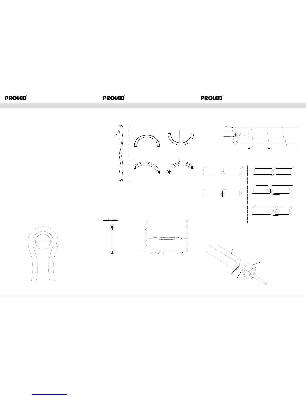
8. Min. b endin g diame ter 120 mm,se e Fig. 1.
Min . Biege durch messe r 120 mm, s iehe Fi g. 1
9. Do not t wist th e light a s Fig.2 a nd Fig. 3. / Ni cht ver drehe n gemäß F ig. 2 und 3 .
10. Do no t hang th is flex l ight in s ky as Fig .4. / Nic ht in der L uft auf hänge n wie in Fi g. 4
11.C uttin g at wron g locat ion wil l resul t in a fail ure of li ght! Se e Fig. 5.
Sch neide n an fals cher St elle fü hrt zu Fu nktio nsaus fall! S iehe Fi g. 5.
Users manual / Bedienungsanleitung
Users manual / Bedienungsanleitung Users manual / Bedienungsanleitung
MBN GmbH, Balthasar-Schaller-Str. 3, 86316 Friedberg - Germany
www.proled.com
MBN GmbH, Balthasar-Schaller-Str. 3, 86316 Friedberg - Germany
www.proled.com
MBN GmbH, Balthasar-Schaller-Str. 3, 86316 Friedberg - Germany
www.proled.com
ACC ESSOR IE S / ZUBEH ÖR
IP6 5 Acc ess ori es Ki t / IP6 5 Zub ehö r Kit
Sin gle End C onnec tion / Ei nseit iger Ans chluß verbi nder
L34 1A02 = Le ft side / l inke Se ite
L34 1A03 = Ri ght sid e / recht e Seite
01 (o r 02) Fro nt Conn ector / Vo rd. Ansc hl.
Cov er / Abde ckung
Ant i-ski dding c lip / Ant i-Rut sch-K lamme r
HST / S chrum pfsch lauch
End C ap Acces sorie s Kit / End kappe n-Kit A rt. L34 1A01
End C ap / Endk appe
Sha ding Sh eet / Abd eckka ppe
HST / S chrum pfsch lauch
1 pc/ St.
1 pc/ St.
1 pc/ St.
1 pc/ St.
1 pc/ St.
2 pcs /St.
1 pc/ St.
Fro nt Conn ector Ac cesso ries Ki t / Verbin dungs ansch luß-K it
Rem ark: HS T--Hea t Shrin k Tube
Aux iliar y Kit / Erg änzun gs-Ki t Art . L65XT 909
Glu e / Klebe r
1 pc/ St.
Rem ark: HS T--Hea t Shrin k Tube
Page 2
PCB
5
3
4
Users manual / Bedienungsanleitung
Users manual / Bedienungsanleitung Users manual / Bedienungsanleitung
MBN GmbH, Balthasar-Schaller-Str. 3, 86316 Friedberg - Germany
www.proled.com
MBN GmbH, Balthasar-Schaller-Str. 3, 86316 Friedberg - Germany
www.proled.com
MBN GmbH, Balthasar-Schaller-Str. 3, 86316 Friedberg - Germany
www.proled.com
12 0m m
Lig ht Surf ace
Lic htaus tritt
CAU TION
ACH TUNG
ASS EMBLY AN D INS TALLAT ION
ZUS AMMEN BAU UND M ONTAGE
1. Turn of f the ele ctric ity bef ore ope ratio n.
Vor de n Arbeit en bitt e Zulei tung un terbr echen .
2. Cutt ing the l ight at c orrec t locat ion (if n eeded ).
Leu chtmi ttel au f erfor derli ches Ma ß zusch neide n (fall s notwe ndig) .
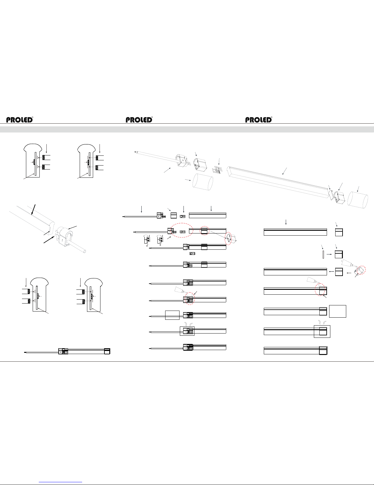
3. Asse mble li ght acc ordin g to Fig. 8.
Zus ammen bau des L eucht mitte ls gemä ß Fig. 8.
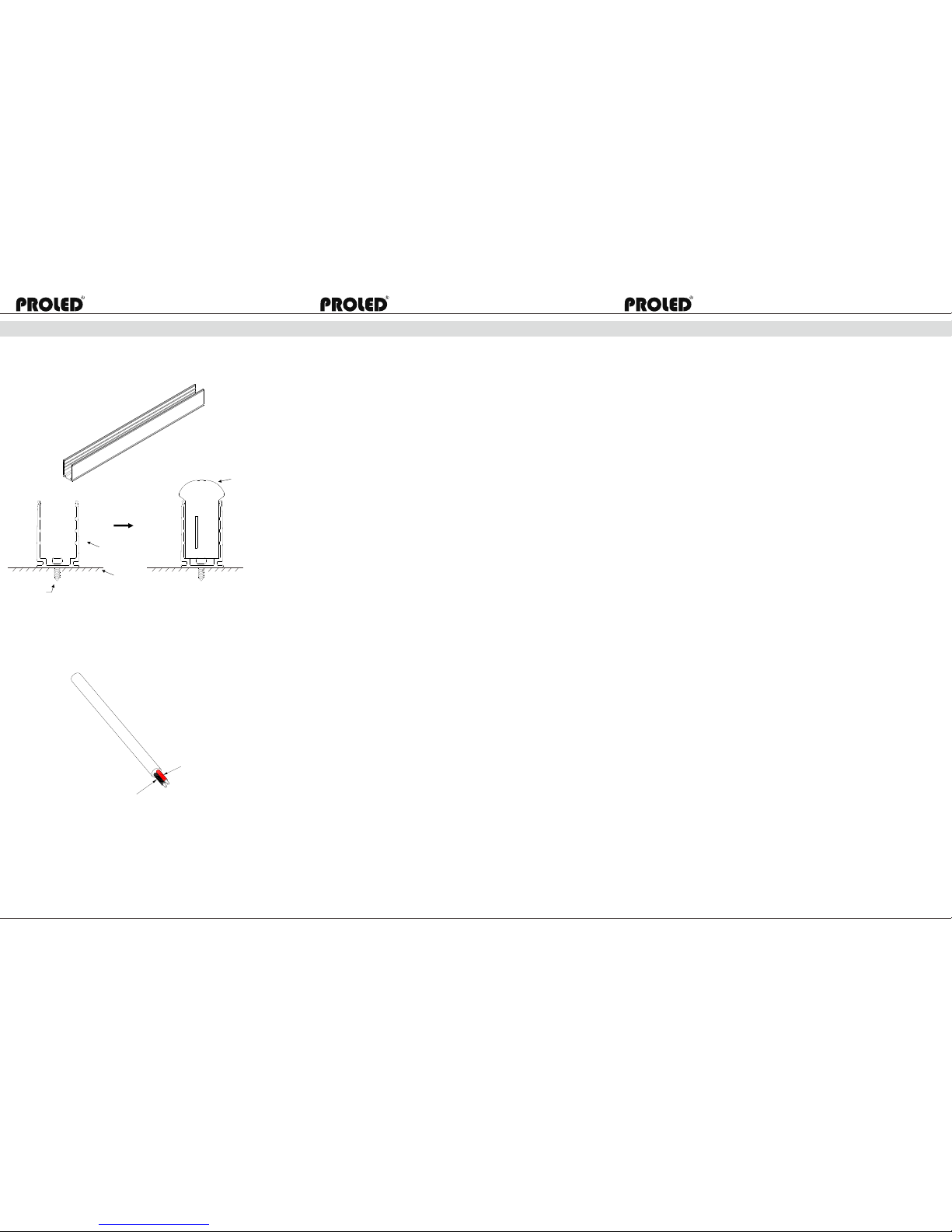
4. Inst all U cha nnel an d light a ccord ing to Fi g.9.
Bef estig ungsp rofil g emäß Fi g. 9 befe stige n.
5. Wiri ng all co nnect ors to th e power l ine and c hecki ng whol e circu it wiri ng.
Cab le colo r codin g basic s Refer t o Fig. 10.
Sch ließe n Sie all e Verbin dungs stück e an die Zu leitu ng an und ü berpr üfen al le Kabe l.
Far bcodi erung d er Kabe l siehe F ig. 10.
1. Suit able fo r mount ing on no rmall y flamm able su rface s
Mon tierb ar auf no rmal en tflam mbare n Oberf läche n.
2. Use on ly fact ory-r ecomm ended c onnec tors an d acces sorie s.
Nur m it orig inale n Verbin dern un d Zubeh ör verw enden .
3. To ens ure its l ong lif e span, o perat e the lig ht prop erly in a ccord ance to t he inst ructi ons.
Um ei ne lang e Leben sdaue r zu gewä hrlei sten, b etrei ben Sie d as Leuc htmit tel nur
gem äß der Be dienu ngsan leitu ng.
4. Do n ot oper ate in mo re than 4 5°C amb ient te mpera ture.
Nic ht bei Um gebun gstem perat ur über 4 5°C bet reibe n
5. Asse mble th e Conne ctor co rrect ly as Fig .6.
Verb indun gsstü ck gemä ß Fig. 6 ko rrekt z usamm enbau en
6. Max. r unnin g lengt h depen ds on the e nergi zing wa y as Fig. 7 show n.
Max . benut zbare L änge hä ngt von d er Eins peisu ng, wie i n Fig 7 ab.
7. Do not o perat e light w hen amb ient te mpera ture is b elow 0° C that ma y injur y the lig ht.
Bit te Leuc htmit tel nic ht unte r 0°C Umg ebung stemp eratu r betre iben.
FIGUR ES
BILDE R
Fig .1 Min imu m ben t dia met er 12 0mm
Min imale r Biege radiu s 120 mm
Twis t the lig ht is for bidde n and cor rect be nding w ay
Verdrehen des Flex Tube s ist ver boten . Korre ktes bi egen
Lig ht Surf ace
Lic htaus tritt
√
Lig ht Surf ace
Lic htaus tritt
×
×
Lig ht Surf ace
Lic htaus tritt
×
√
Fig .2 Fig .3
Lig ht Surf ace
Lic htaus tritt
Lig ht Surf ace
Lic htaus tritt
Fig .4 Han g sus pen ded i nst all ati on as t he pi ctu re il lus tra ted i s
for bidde n.
Mon tage ge mäß nac hfolg enden B ilder n ist nic ht zulä ssig.
① ②
×
×
Fig .5 Uni t cut tin g gui de
Zus chnit tanle itung
Lig ht Surf ace
Lic htaus tritt
PCB
LED
PVC
100 mm
Cut ting li ne
Sch nittl inie
√
×
×
×
The c orrec t cutti ng way, R= 90°
Ric htige S chnit tweis e, R=90 °
Wave c uttin g is inco rrect
Well iges sc hniei den ist f alsch
R>9 0° is inc orrec t
R>9 0° ist fa lsch
R<9 0° is inc orrec t
R<9 0° ist fa lsch
Beg innin g cutti ng
Sch nitta nfanf g
Fig .6 Cor rec t ins ert p osi tio n of co nne cto r pin s
Ric htige E inbau art der Verbindungpins
For 0 1 Typ e Fro nt Co nne cto r / Für Ve rbi ndu ngs ans chl uß Typ 01
Lig ht Surf ace
Lic htaus tritt
01 Fr ont Con necto r
01 Ver bindu ngsan schlu ß
Con necto r Pins
Verb indun gspin s
0
1
Page 3
PCB
LED LED
LED
LED
PCB
PCB
PCB
PCB
8
6
7
Users manual / Bedienungsanleitung
Users manual / Bedienungsanleitung Users manual / Bedienungsanleitung
MBN GmbH, Balthasar-Schaller-Str. 3, 86316 Friedberg - Germany
www.proled.com
MBN GmbH, Balthasar-Schaller-Str. 3, 86316 Friedberg - Germany
www.proled.com
MBN GmbH, Balthasar-Schaller-Str. 3, 86316 Friedberg - Germany
www.proled.com
Con necto r Pins
Verb inder P ins
Con necto r Pins
Verb inder P ins
√
×
Lig ht Surf ace / Lic htaus tritt
02 Fr ont Con necto r
02 Ver bindu ngsan schlu ß
Con necto r Pins /
Verb inder P ins
For 0 2 Typ e Fro nt Co nne cto r /
Für 0 2 Typ Ve rbi ndu ngs ans chl uß
Con necto r Pins
Verb inder P ins
√
×
Con necto r Pins
Verb inder P ins
Fig .7 Ene rgi zin g Way / An sch luß art
Sin gle end c onnec tion: M ax. len gth 10 m
ATTE NTI ON: F or ou tsi de us age o nly m ax. 7 m
Ein seiti ger Anschluss: Max. Länge 10 m
ACH TUNG: B ei Verwendung im Freien max. 7 m
0
2
Lig ht Surf ace /
Lic htaus tritt
G
lue /
K
l
e
ber
Gl
ue /
K
l
e
ber
1.
2.
3.
4.
5.
6.
7.
8.
Ste p / Schri tt
1.
2.
3.
4.
5.
6.
Gl
u
e /
Kl
e
b
e
r
Glue s on the ed ges /
Kleb er an den E nden
Wit h 1/3 glu es /
Zu 1/ 3 Klebe r fülle n
Glu e on the ed ges /
Kle ber an de n Enden
Pins on t he back o f PCB
is corr ect. Re fer to Fi g. 6 /
Pins an d er Rück seite d er
Plati ne ist ri chtig .
Siehe F ig. 6.
Fig .8 IP6 5 Con nec tor A sse mbl e / Zus amm enb au IP 65 Ans chl uß
Dia gram
Fron t Conne ctor
Verbi ndung sansc hluss
Fron t Conne ctor
Verbi ndung sansc hluss
Anti -skid ding Cl ip
Anti -Ruts ch-Kl ammer
Anti -skid ding Cl ip
Anti -Ruts ch-Kl ammer
Cove r
Abde ckung
Cove r
Abde ckung
Ligh t Surfa ce
Lich taust ritt
Ligh t Surfa ce
Lich taust ritt
End Ca p
Endk appe
HST
Sch rumpf schla uch
HST / Sc hrump fschl auch
Shad ing She et
Abde ckkap pe
Pay att entio n to
wide op en side
Aufpa ssen au f weit
geöff nete Se ite
Step / Sc hritt
Connector P ins
Verbinder P ins
Connector P ins
Verbinder P ins
HEAT
HITZE
HEAT
HITZE
End C ap
End kappe
End C ap
End kappe
Sha ding Sh eet
Abd eckka ppe
Page 4
9
10
Users manual / Bedienungsanleitung
Users manual / Bedienungsanleitung Users manual / Bedienungsanleitung
MBN GmbH, Balthasar-Schaller-Str. 3, 86316 Friedberg - Germany
www.proled.com
MBN GmbH, Balthasar-Schaller-Str. 3, 86316 Friedberg - Germany
www.proled.com
MBN GmbH, Balthasar-Schaller-Str. 3, 86316 Friedberg - Germany
www.proled.com
11
Scre w
Schr aube
Alum inium U -chan nel
Alum inium profi l
Insta llati on Surf ace
Monta geobe rfläc he
Fig .9 Ins tal lat ion G uid e / Mon tag ean lei tun g
For C ommon Al uminu m U-cha nnel
Für S tanda rd Aluminiumprofil
Ligh t Surfa ce
Lich taust ritt
Fig .10 Ca ble c olo r cod ing b asi cs / Ka bel -Fa rbc odi eru ng
Red wir e
Rote Ad er
Black w ire
Schwa rze Ade r
2-w ires ca ble:
Red w ire con nect to t he anod e (+)
Bla ck wire c onnec t to the ca thode ( -)
2-A drige s Kabel :
Rot e Ade r an Anode (+) anschließen
Sch warze Ader an Kathode (-) anschli eße n
GARANTIEBESTIMMUNGEN
Vom Tag des Kaufes an gewähren wir für unsere Produkte bei sachgemäßer Verwendung im
Falle von Qualitätsmängeln kostenlose Reparatur oder Austausch, außer in folgenden Fällen:
1. Defekte durch unsachgemäßen Betrieb.
2. Schäden durch unautorisierte Reparatur, Modifikation, falschem Anschluss.
3. Schäden durch Transport, Vibration usw. nach dem Kauf.
4. Schäden durch Erdbeben, Feuer, Blitzschlag, Verschmutzung oder Überspannung.
5. Schäden durch unsachgemäße Lagerung bei zu hohen Temperaturen, feuchter Umgebung
oder in der Nähe von Chemikalien.
6. Wenn das Produkt upgedatet wurde.
SICHERHEITSHINWEISE
1. Installieren Sie diesen Flex Tube PRO nicht während eines Gewitters, bei starken Magnetfeldern
oder Hochspannungsfeldern. Achten Sie auf einen korrekten Anschluss, um das Risiko einer
Beschädigung von Komponenten oder eines Kurzschlusses zu minimieren.
2. Stellen Sie immer eine ausreichende Kühlung sicher, um die zulässige Betriebstemperatur
einzuhalten.
3. Überprüfen Sie, ob das Netzteil den Leistungsanforderungen des Flex Tube PRO entspricht
und die Polung korrekt ist.
4. Führen Sie alle Anschlüsse nur im stromlosen Zustand durch und stellen Sie vor der
Inbetriebnahme sicher, dass kein Kurzschuss vorhanden ist.
5. Zu Informationen über Updates wenden Sie sich bitte an Ihren Händler.
LIMITED WARRENTY,
In case of quality problems we provide free repair or replacement within one year from the day of
purchase, if this product has been used properly in accordance with the user's manual, except in
following cases:
1. Any defects caused by wrong operation.
2. Any damages caused by unauthorized removal, maintenance, modifying, incorrect connection.
3. Any damages due to transportation, vibration etc. after purchase.
4. Any damages caused by earthquake, fire, lightning, pollution and abnormal voltage.
5. Any damages caused by negligence, inappropriate storing at high temperatures and humidity
or near harmful chemicals.
6. Product has been updated
SAFETY WARNINGS
1. Please don't install this Flex Tube PRO during thunderstorms, intense magnetic or high-voltage
electrical fields. To reduce the risk of component damage and fire caused by a short circuit,
make sure, that all connections are correct.
2. Always be sure to mount this unit in an area with proper cooling to avoid overheating.
3. Check voltage and power requirements of the Flex Tube PRO as well as the polarity of the
power supply.
4. Never connect any cables while power is on and always assure correct connections to avoid
short circuits before switching on.
5. For update information please consult your supplier.
 Loading...