

Page 1
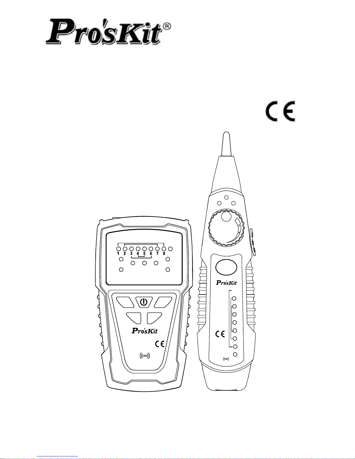
MT-7028
Network Toner & Probe Kit
SCAN
TEST
POL
MT-7028
MT-7028
NETWORK TONER & PROPE
TRANSMITTER
RECEIVER
NETWORK
TONER & PROPE
1
2
3
4
5
6
7
8
G
LED
OFF
NCV
1-8 RJ45
2-7 RJ11 6P/6C
3-6 6P/4C
4-5 6P/2C
POL-/G
POL+/R
1-8 RJ45
2-7 RJ11 6P/6C
3-6 6P/4C
4-5 6P/2C
G
POL
TEST
POWER
BAT LOW
SHORT
Ω
Ω
SCAN
SCAN
User’s Manual
1
st
Edition,
©2014 Copyright by Prokit’s Industries Co., Ltd.
Page 2

1
Thank your for your purchase of Pro’sKit MT-7028 Network Toner &
Probe Kit. The Toner and Probe set is used to quickly trace and
identify cables or wires within a group and also check the operation
of telephone lines. With proper use and care, this instrument will
provide many years of reliable service.
Index
Overview……………………………………………………….……….1
Features………………………..……………………….………….…..1
Unpacking………………………………………………………………3
Specifications………………………………………………..…………3
Safety Information………………..……………………………………5
MT-7028 Transmitter…………………….……………………………6
MT-7028 Receiver…………………………….………………………9
Locating and Isolating Cables………………………………………11
Locating Individual Wire Pairs with the MT-7028 Analog Function
Isolating Cables………………………………………………………12
Cable Map testing……………………………………………………14
Live telecommunication equipment and router test………………18
Coaxial Cable & Continuity Testing…………………….….………19
Validating Telephone Service and Polarity………………..………20
NCV (Non-Contact Voltage) Testing…………………….….………21
Battery Life and Replacement………………………………………22
Maintenance & Trouble shooting……………………………………23
OVERVIEW
The MT-7028 let you easily locate and verify the cable status and
troubleshoot wiring for continuity, shorts, opens and crossover on
RJ45 Lan cable Cat 5、5e、6、7 (UTP/STP)、RJ11/12 Telephone cable
Cat. 3 (2/4/6 pin) & normal solid/Stranded wire by alligator clips
patch cord. Ideal for all installation and maintenance fields of
telecommunication, networking, datacom, Audio/Video, cable TV,
and all weather cabling, etc.
FEATURES
Wire Tracing up to 3KM
• The tone and probe kit lets you easily track wire directly in
connection with live telecommunication equipment and router.
Cable Mapping & status Indication up to 300M
• Fast/Slow scan functions.
• Display the result of pin to pin cable mapping.
Page 3

2
• Display cable status and troubleshoot wiring for continuity, shorts,
opens and crossover.
Non Contact Voltage detection
• Tests voltage from 90 ~ 1000V, special design to make sure the
power is off before testing for circuit protection.
Polarity indication
• Identify the telephone line polarity easily.
Energy saving
• Automatically powers off after 1 hour of no operation.
ADVANCED FEATURES
• MT-7028 Transmitter generates: 1KHz audio signal with
two-tone (high / low) for selection. The maximum distance of
transmitter is
≧
3 kilometers. Works with MT-7028 receiver
by volume adjustment feature can precisely find the break
point in the range of 10~30cm. The MT-7028 receiver
contains indicated LEDs which is more accurate for testing.
• MT-7028 Transmitter works with the receiver for cable
mapping by LED lights indication. The instrument can verify
cable status for continuity, shorts, opens and crossover on
RJ45 Lan cable and RJ11 telephone cable and test
shielding/ unshielded wire. The maximum length that can be
tested is 300 meters.
• MT-7028 Transmitter: LED indicators to detect the common
wire resistance (> 300Ω) for bad connection.
• MT-7028 Transmitter has 60V AC or DC 48V protection.
Telecommunications equipment and routers can be tested in
live Electrical environments without turning off the power.
The transmitter can also identify the positive and negative
polarity telephone lines.
• MT-7028 Transmitter:with low battery indication function
and will turn off automatically after one hour non-working.
• MT-7028 Receiver:with Non Contact Voltage detection
feature which can detect AC voltage from 90~1000V to avoid
danger and damage by detecting the voltage in advance.
• MT-7028 Receiver:with LED lighting and earphone jack to
allow the product to be used in noisy or dark environments.
Page 4
3
MT-7028 Transmitter:with dual jacks for RJ45 Lan cable and RJ11
telephone line. The transmitter can be tested with a patch cord for
RJ45 / RJ11. Coaxial cable, general cable and various wiring boards
can be tested by using with alligator clip cable.
PACKING
The MT-7028 product comes with the accessories listed below. If
any accessory is damaged or missing, contact the place of purchase
immediately.
MT-7028 Network Tone and Probe Kit packing:
• MT-7028 Transmitter.
• MT-7028 Receiver.
• RJ45 (8 pin) to RJ45 (8 pin) patch cords.
• RJ11 (6 pin) to RJ11 (6 pin) patch cords.
• RJ11 (6 pin) to alligator clips patch cord.
• Earbud
• Storage bag.
• User’s manual.
SPECIFICATIONS
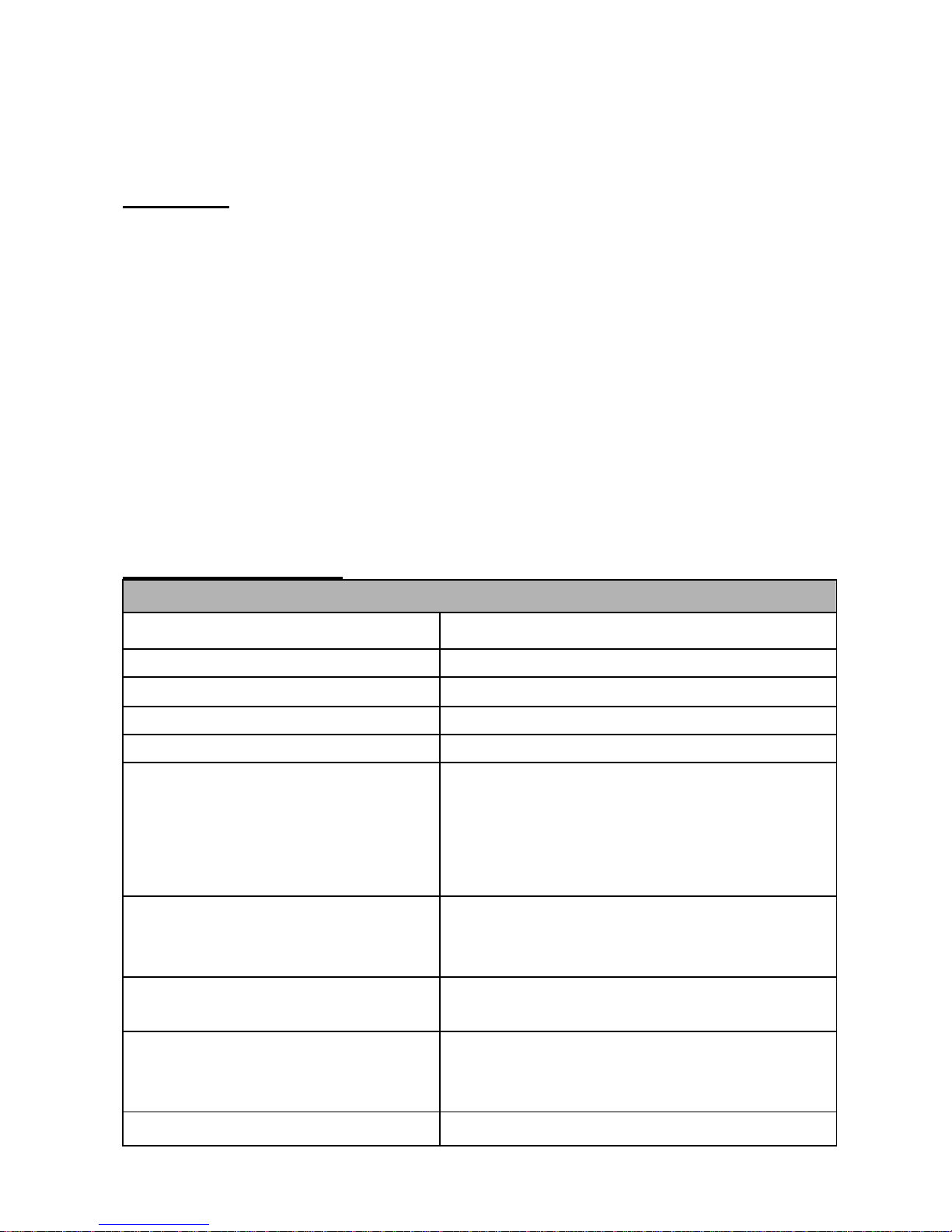
MT-7028 Transmitter specifications
Tone frequency 1kHz
Max. distance of transmission ≧3km
Max. distance of cable map 300m
Max. working current ≦65mA
Tone mode Hi/Low two-note tone
Compatible connectors
RJ45(8 pin)/RJ11(6 pin) compatible
connectors for RJ45(8 pin)、
RJ11/12(6P/2C/4C/6C) cable map and
RJ45 tone、RJ-11(6 pin) connectors for
RJ11/12(6P/2C/4C/6C) tone
Cable types tested
RJ45 Lan cable Cat 5、5e、6、7
(UTP/STP)、RJ11/12 Telephone cable Cat
3 (6P/2C/4C/6C)
Function selection
5 Push button switch (POWER、SCAN、
TEST、Ω、POL)
Continuity test
1 LED (≦300Ω), Coaxial cable & normal
solid/Stranded wire by alligator clips patch
cord.
Max. signal voltage 8Vp-p
Page 5
4
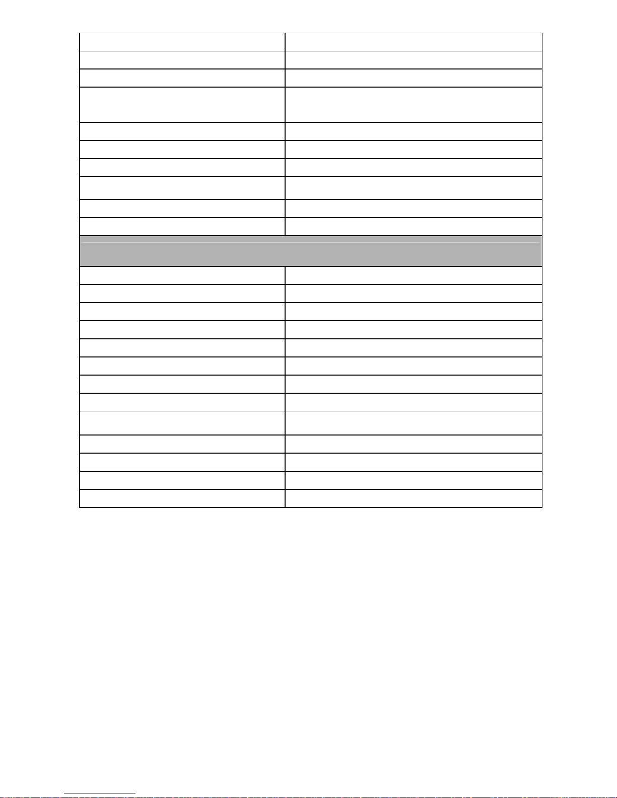
Cable map indication 8 LEDs, Fast/Slow dual speed
Shielded indication 1 LED
Phone line polarity indication 1 Dual color LED
Live telecommunication
equipment test and router test
Yes
Voltage protection AC 60V or DC 48V
Auto power off 1 hour
Low battery display 6.5V (Power LED flashes)
Battery type DC 9.0V (NEDA 1604/ 6F22 DC9V ×1pcs)
Dimension (L×W×D) 138×80×35 mm
Weight 140g
MT-7028 Receiver specifications
Frequency 1kHz
The Max. working current ≦50mA
Compatible connectors RJ45(8 pin)/RJ11(6 pin)
Function selection 3 Position mode switch (NCV、OFF、LED)
Earphone jack 1
Signal status indication 1 LED & Buzzer
Cable map indication 8 LEDs
Shielded indication 1 LED
NCV indication 1 LED (AC90~1000V,≥50mm,≤100mm)
LED illumination 1 LED
Battery type DC 9.0V (NEDA 1604/ 6F22 DC9V ×1pcs)
Dimension (L×W×D) 198×45×33 mm
Weight 80g
Transmitter drop test(Shock and Vibration):1 Meter
Operating temperature:0 ~ 50℃ (32 ~ 122℉)
Storage temperature:-10 ~ 60℃ (14 ~ 140℉)
Operating humidity:20% - 75% RH
Storage humidity:10% - 90% RH
Operating altitude:3,000 meters
Storage altitude:10,000 meters
Page 6
SAFETY INFORMATION
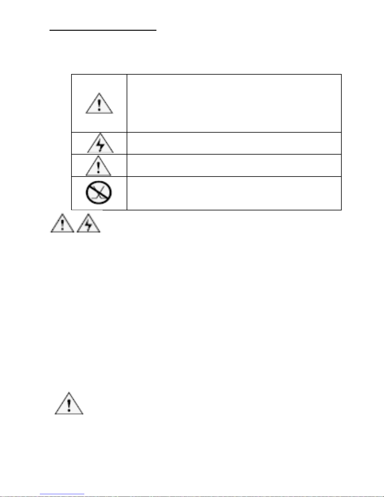
Table 1 describes the international electrical symbols used on the
tester and in this manual.
Table 1. International Electrical Symbols
Warning:Risk of personal injury. See
explanations in the manual.
Caution:Risk of damage or destruction to
equipment or software. See explanations in the
manual.
Warning:Risk of electric shock.
Please keep an eye on the status or function of
the equipment while operating.
This equipment not for connection to public
communications networks, such as active
telephone systems.
Warning
• Never use the Transmitter or Receiver on circuits of more
than AC 60V or DC 48V.
• Never use the Transmitter, Receiver, or test leads if they
are damaged. Inspect the cases and test leads for
damage before use.
• Disconnect unused test leads and connectors from the
Transmitter when testing telephone circuits.
• Never open the case except to change the battery or the
fuse; no user-serviceable parts are inside.
• Turn off the Transmitter or Receiver and disconnect all
test leads before replacing the battery.
• Use only a 9V battery, properly installed in the case, to
operate the Transmitter and Receiver.
• If this equipment is used in a manner not specified by the
manufacturer, the protection provided by the equipment
may be impaired.
Caution
• Avoid touching the Receiver tip to patch panel
connections and using the tip to dig into cable bundles.
Doing so regularly may damage the Receiver tip over
time.
5
•
To avoid unreliable test results, replace the battery as
soon as the low battery indication appears.
Page 7
INTRODUCTION
MT-7028 Transmitter:
SCAN TEST
POL
MT-7028
NET W OR K T ONE R & P R OP E
TRANSMITTER
POL - /G
POL+ /R
1-8 R J45
2-7 R J 11 6P /6C
3-6 6P/4C
4-5 6P/2C
G
PO L
TEST
POWER
BAT LOW
SHORT
Ω
Ω
SCAN
2 1
3
4
5
6
11
12
9
10
8
7
14
13
15
16
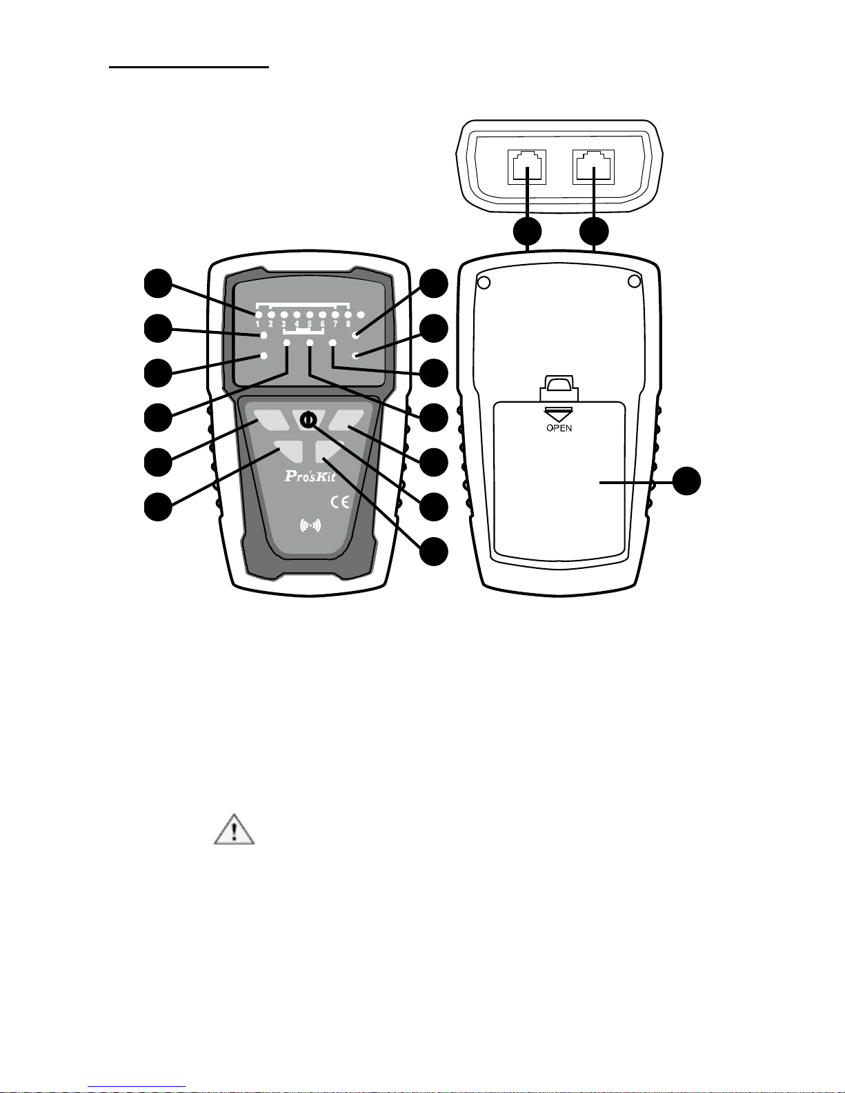
Figure 1 MT-7028 Transmitter Diagram
1. RJ45(8 pin)/RJ11(6/4/2 pin) Compatible connectors:
Used for RJ45/ RJ11 cable mapping and RJ45 cable
tracing. When used for RJ45/ RJ cable mapping, please
connect the cable to RJ45(8 pin)/RJ11(6/4/2 pin)
Compatible connectors of MT-7028 receiver to start the
function.
Caution! Do not plug in any live cable to the
RJ45(8 pin)/RJ11(6/4/2 pin) Compatible
connectors. RJ11 cable tracing can not be
operated by this connector.
6
Page 8

2. RJ11(6 pin
) Connectors:Used for RJ11 (6P/6C/4C/2C)
cable tracing.
Caution! Do not plug in any live cable over AC
60V/ DC 48V to the transmitter.
3. 「1~8、G」
Cable map & Shielded indication:Work with
MT-7028 receiver for RJ45/ RJ11 cable mapping
indicated by 8 LED and for shielded/unshielded indication.
4. 「SHORT」 Continuity test indication:When the
indication lights up means the resistance of cable is less
than 300Ω or the cable is short. If the indication doesn’t
light up, it means the resistance of the cable is over 300Ω
or the cable is open.
5. 「Ω」 Continuity function indicator:Push “
” button
to start continuity/ short features when the indication light
up.
s
6. 「SCAN」 Locating and Isolating Cables function
indicator:Push “
” button for cable tracing feature.
When the indication LED flickers slowly, it means low-tone
tracing function is working. Push “scan” button again to
switch to high-tone tracing function and the indication LED
will flicker faster.
7. 「POWER/BAT LOW」 Power ON/OFF & Battery low
indicator:Push “
” button to turn on the transmitter.
When the indication lights up, the product is working.
Select different functions by pushing other buttons.
When the battery voltage is less than 6.5V, the indication
LED will flicker, please replace a new battery for the
product.
8. 「TEST」 Cable map & Shielded function indicator:
Pushing “
” for cable mapping and shielded function
indication. When the LED flickers slowly, the low speed
scan is working. Push the TEST button again, the fast
speed scan will be operated.
9. 「POL-/G,POL+/R」 Phone line polarity indication:
This is a dual color LED. When the red alligator clip
connects positive polarity and black alligator clip connects
negative polarity, the LED will be in RED color. If the
7
Page 9

alligator clips
connect in opposite way, the LED will be in
GREEN color. If the LED did not light up, it means there is
no electrical on the cable.
10. 「POL」 Phone line polarity function indicator:Push
“
” button to operate the feature of phone line polarity
checking.
11. 「
」 Isolating Cables function push button:Push
“
” button for cable tracing feature. When the indication
LED flickers slowly, it means low-tone tracing function is
working. Push “scan” button again to switch to high-tone
tracing function and the indication LED will flicker faster.
12. 「
」 Continuity function push button:Push “Ω”
button to start continuity/ short features when the LED
lights up.
13. 「
」 Power ON/OFF push button:Push “ ” button
to turn on the transmitter. Push the button again to turn off
the transmitter and the “POWER/ BAT LOW” indicator will
be off as well.
14. 「
」 Cable map & Shielded function push button:
Push “
” for cable mapping and shielded function
indication. When the light flickers slowly, the low speed
scan is working. Push the TEST button again, the fast
speed scan will be operated.
15. 「
」 Phone line polarity function push button:Push
“
” button to operate phone line polarity function.
16. Battery cover
8
Page 10
MT
-7028 Receiver:
MT- 7028
RECEIVER
NETWORK
TONER & PROPE
1
2
3
4
5
6
7
8
G
LED
OFF
NCV
1-8 RJ45
2-7 RJ 11 6P/6C
3-6 6P/4C
4-5 6P/2C
SCAN
1
2
7
4
3
5
11
9
13
12
8
2
6
10
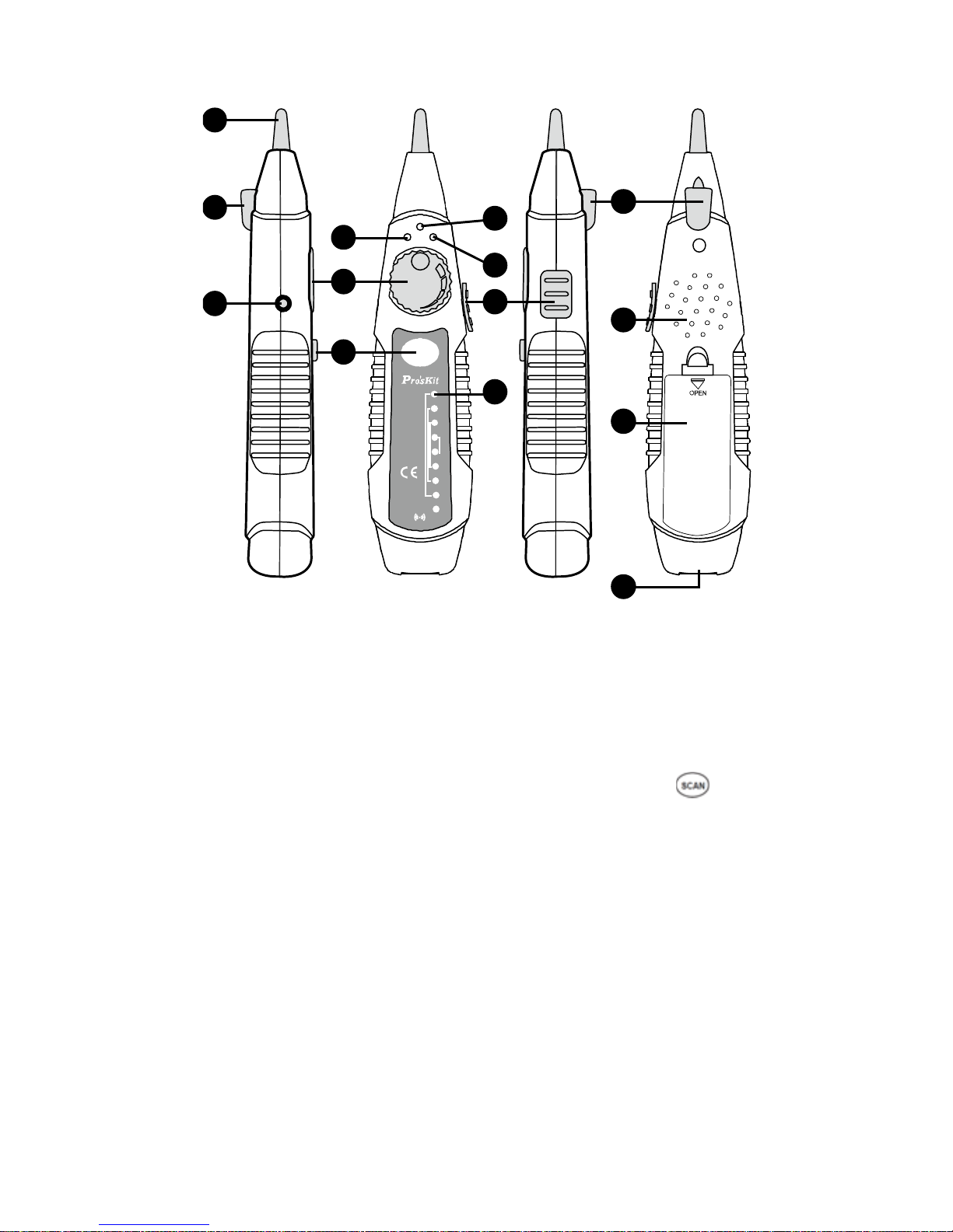
Figure 2 MT-7028 Receiver Diagram
1. Probe:Used for cable tracing and NCV detection.
2. LED illumination:Used for dark working environment.
3. Power ON/OFF indicator:The indicator will be lighted up
when the switch at LED or NCV position and the receiver
started the functions. When the switch at OFF position,
the indicator will be light up when pushing “
” button for
cable tracing.
4. NCV indicator:When the probe closes to the tested
object to detect the voltage, the indicator will light up if the
object carried AC90~1000V. If the indicator did not light up,
there is no voltage detected from the object or the AC
voltage is less than 90V.
5. Signal status indicator:When doing cable mapping by
probe, if the indication LEDs (1~8) more light up, the
signal is stronger.
9
6. V
olume control:By adjusting the volume from high to low
to adjust the sensitivity of probe. Move the position of
receiver from 30 cm to 10cm to find out the cable you are
tracing.
Page 11

7. Earpho
ne jack Φ3.5mm:Earphone can be used when
the working area is noisy.
8. Function selection:3 Position mode switch (NCV、
OFF、LED)
9. Speaker:When “SCAN” feature is working, if the speaker
is louder, the signal is stronger.
10. 「
」 Locating and Isolating Cables function push
button: When pushing the “
” button, the feature starts
and the battery indicator will be light on.
11. 「1~8、G」 Cable map & Shielded indication:Work with
MT-7028 transmitter for RJ45/ RJ11 cable mapping
indicated by 8 LED and for shielded/ unshielded
indication.
12. RJ45(8 pin)/RJ11(6/4/2 pin) Compatible connectors:
Used for RJ45/ RJ11 cable mapping. When used for
RJ45/ RJ11 cable mapping, please connect the cable to
RJ45(8 pin)/RJ11(6/4/2 pin) Compatible connectors of
MT-7028 transmitter to start the function.
Caution!
Do not plug in any live cable to the RJ45(8
pin)/RJ11(6/4/2 pin) Compatible connectors.
13. Battery cover.
10
Page 12
OPERATION
Locating and Isolating Cables:
Using MT-7028 Networking Tone & Probe kit to locate and insolate
cables using the 1KHz analog, also trace twisted wires (UTP, STP,
Cat 5e, Cat 6) and telephone line (Cat 3). Use with a patch cord for
RJ45 / RJ11. Coaxial cable, general cable and various wiring boards
can be tested by using with alligator clip cable.
Warning
• It is not intended to be used on live wires with a DC
power source (e.g., live telephone lines), nor will it work
on wire pairs that are carrying AC signals.
• Use RJ45(8 pin)/RJ11(6/4/2 pin) compatible connector
for RJ45 cable tracing. Use RJ11(6 pin) connector for
RJ11(6P/6C/4C/2C) cable tracing. Use RJ11 (6 pin)
connector and work with alligator clips for coaxial cable,
general cable and various wiring boards.
Caution
• To locate and isolate cables using the 1KHz analog
toning mode, please avoid interference sources like
electronic devices with adapter, induction coil, and
motors nearby. White noise from MT-7028 Receiver is
normal when your Transmitter is near any of the
interference. If you cannot locate the signal on
2-conductor cables, the cable may be shorted. Please
keep away from the interference sources or turn off the
electronic devices.
• The position on the MT-7028 Transmitter and Receiver
lets you use the Receiver to trace using an analog 1KHz
tone. When using the Receiver to isolate the tone source
in the cable bundle or at the patch panel, the signal
might be interfered with or decreased and the signal will
not pass through metal tubes.
• It is not necessary to touch the Receiver’s tip to the
cabling or patch panel when searching for the
Transmitter’s signal.
• Make sure the black alligator clip of the Transmitter is
connected to the ground before use.
MT-7028 Transmitter provides two 1 KHz analog toning modes,
Hi/Low two-note tone, for location and isolating cables. Both toning
signals are available at all connectors on the Transmitter.
11
Page 13
Loca
ting Individual Wire Pairs with the MT-7028 Analog
Function
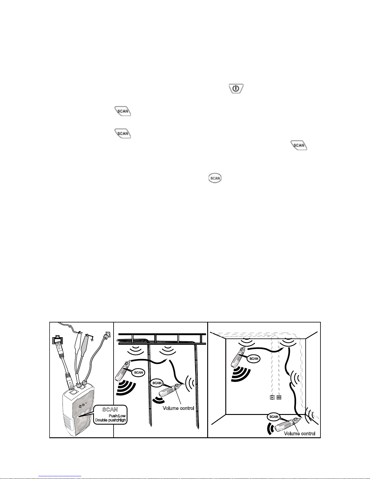
To locate cables, do the following steps (Figure 3):
1. Connect the black alligator clip of the Transmitter to the
ground, and then connect the red clip to a jack or
punch-down block as shown in Figure 3.
2. As the Figure 3 shown, when push
, the indicator of
“POWER/ BAT LOW” will light up and turn on the power.
Push
button for cable tracing. When the RED
indicator flickered, the low-tone cable tracing is working.
Push
button again to feature the high-tone cable
tracing, the RED indicator will flicker faster. Push
button again, the RED indicator will be stopped and
standby for next operation.
3. AS the figure 3 shown, push “
” on receiver to operate
cable tracing function. The tracing sound will be output
from speaker. When put on earphone, there will be no
sound from speaker, but from the earphone.
4. Use the Receiver to find the general location of the tone at
a cable rack, patch panel, or behind a wall. In locating
mode, the Receiver’s LEDs light up in red from 1 to 8, then
wrap back and light up from 1 to 8 again as the signal
strength increases.
5. Adjust the Volume Control on the Receiver to locate the
wire pairs from 10cm to 30cm.
SCAN
SCAN
SCAN
SCAN
SCAN
Push:Low
Double push:High
RJ45
Jack
RJ11 J
ack
Volume cont rol
Volume cont rol
Ground
Figure 3 Locating cables
12
Page 14
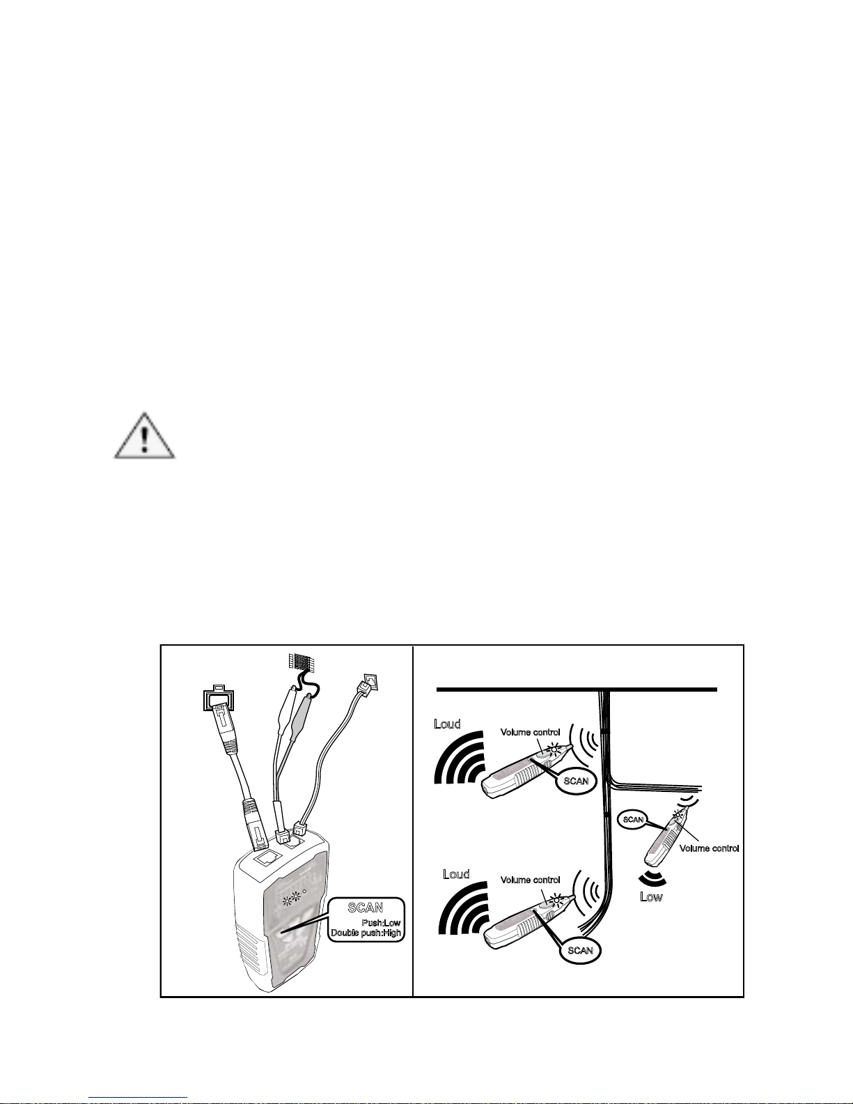
Isolati
ng Cables:
To isolate the tone source in the cable bundle or at the patch panel,
do the steps as described in the previous section of “Locating
Cables”.
1. Strip the cable’s shield to a length of between 30 to 45
centimeters and divide the wires into two parts. Do the
wire separation to isolate the cables to verify the signal of
each part. If the beeper gets louder and LED lights up, you
have located the position you are looking for.
2. Adjust the volume control from high to low to enable
looking for a more difficult to identify wire. Narrowing the
length from 30 to 10 centimeters will help to more
accurately identify the wire pairs.
3. Repeat the steps of 6 and 7 to isolate the bundled cables.
Caution
• If you cannot locate the MT-7028 signal on 2-conductor
cables, the cable may be shorted or opened. Use the
Continuity Test (Fig. 8) to check for shorts or opens on
coax and non-terminated cables.
SCAN
SCAN
SCAN
SCAN
Push:Low
Double push:High
Loud
Loud
Volu me contro l
Volum e c o nt r ol
Volume control
Low
RJ45 Jack
RJ11 Jack
Telephone
block
Figure 4 Isolating Cable
13
Page 15
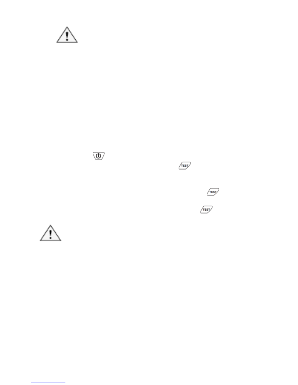
Cable Ma
p Testing:
Caution
• When use the product for RJ45 or RJ11 cable
mapping, please only plug in the cable to
RJ45/RJ11 compatible connector on transmitter.
Do not use RJ11 (6pin) connector.
• You can use the MT-7028 Transmitter or Receiver
to validate the cable map on RJ45/RJ11 by
RJ45/RJ11compatible connector on transmitter.
The cable map function finds the most common
wiring faults on twisted pair cabling: shorts, opens,
and crossed pairs.
1. Connect the MT-7028 Transmitter or Receiver to RJ45/
RJ11 jacks.
2. Push “
”, the indicator of “POWER/ BAT LOW” will light
up and turn on the power. Push “
” on MT-7028
transmitter for cable mapping and shielded function
indication. When the green LED indicator flickers slowly,
the low speed scan is working. Push the “
” button
again, the green LED indicator flickers faster and the fast
speed scan will be operated. Push the “
” button again,
the product will be standby for next operation.
Caution
• Each LED that corresponding to an active pin flashes
briefly, and then should light for about 1 second. For fast
scan cable mapping, the light will be flicker about 0.5
second, from 1 to 8, G. If the cable is open, the LED
indicator will not light up.
• Before cable map testing, repeat the procedures of
“Locating Cables” on page 7 to identify the correct
connector or wires on the other end of the cable if
necessary.
14
Page 16
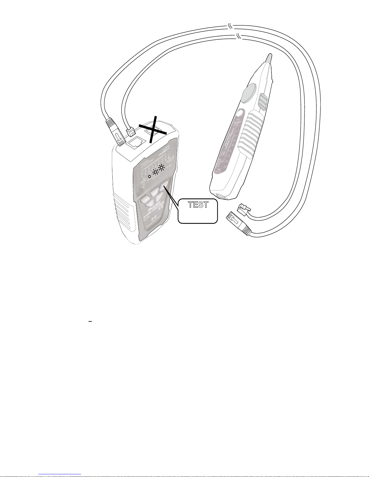
TEST
Push:Slow
Push agai n:Fast
RJ45/RJ 11 Jack
(8P/8C,6P/6C, 6P/4C,6P/2C)
RJ45/RJ 11 Jack
(8P/8C,6P/6C,6P/4C,6P/2C)
Figure 5 Validating Cable Maps
3. Different connectors generate different LED and sound
indications as shown in Figure 6.
• RJ45(8P/8C) LED indication:MT-7028 Transmitter
(from 1-8 seconds in sequence) is synchronized with
the MT-7028 Receiver cable map.
•
RJ11(6P/6C, 6P/4C, 6P/2C) LED indication:MT-7028
Transmitter cable map, 6P/6C each second from 2 to 7
in sequence, 6P/4C each second from 3 to 6 in
sequence, 6P/2C each second from 4 to 5 in sequence
is synchronized with the MT-7028 Receiver cable map.
If it encounters an empty line, the indication will cease.
15
Page 17
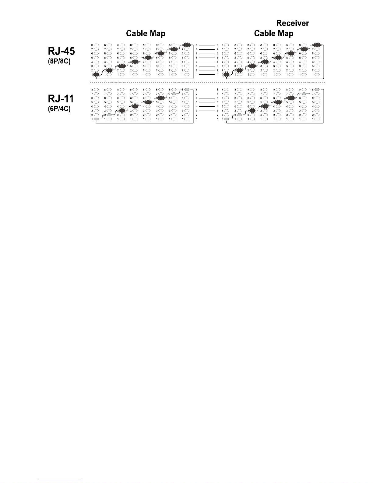
MT-7028 MT-7028Transmitter
Figure 6 Different Connector’s Cable Map
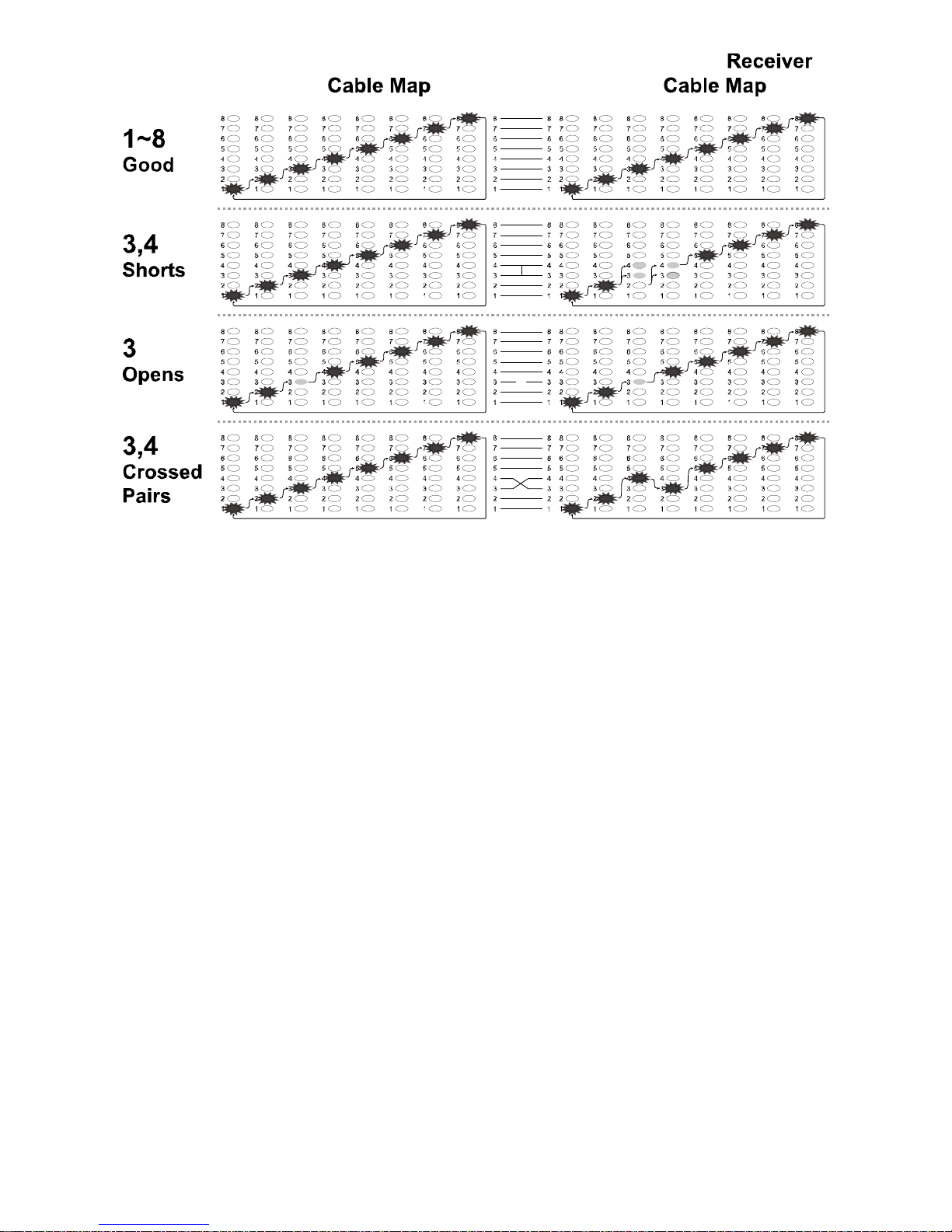
4. You can use the MT-7028 Transmitter and Receiver to validate
the cable map on RJ11 and RJ45 connectors. The cable map
function finds the most common wiring status on twisted pair
cabling: good, shorts, opens, and crossed pairs as shown in
Figure 7.
• Good wiring: Each LED that corresponding to an active
pin flashes briefly and in a stairway order.
• Shorts: If two LEDs turn on for 1 second at the same time,
those two pins are shorted together. If more than 2 wires
are shorted together, the LEDs for the shorted pins
indicate opens.
• Opens: If an LED flashes briefly, then no LEDs turn on,
that pin is open.
• Crossed pairs: If one LED flashes briefly, then another
LED lights for one second, the wire for the first LED is
crossed pairs to the pin for the second LED.
5. Each LED that corresponds to an active pin flashes briefly, it
should light for about 1 second. The brief flash shows which
LED is next in the sequence.
16
Page 18
MT-7028MT-7028
Transmitte
r
Figure 7 good wiring, shorts, opens, crossed pairs
17
Page 19
Li
ve telecommunication equipment and router test:
Caution! The feature can only be used for testing cable
continuity and opens, cannot be used for cross over and short.
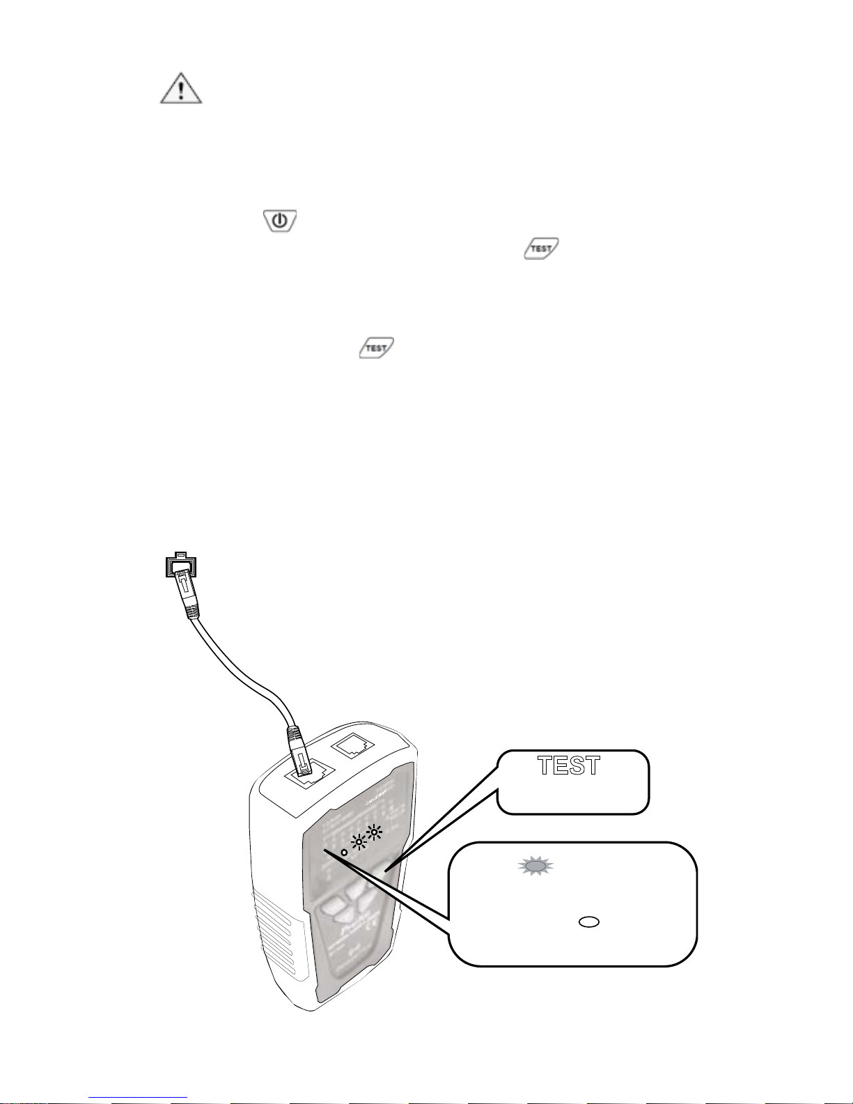
1. According to Figure 8, connect MT-7028 transmitter and
working router by RJ45(8P/8C).
2. Push
button to turn on the power, “POWER/ BAT
LOW” indicator will light up. Push
button on
transmitter to feature cable map function. When the TEST
indication green LED flickers slowly, the slow cable
mapping is working and the red cable map LED starts
scanning. Push
button again, the TEST indication
green LED twinkled fast, the fast cable mapping is
working and the cable map LED starts scanning. Push the
button again, the TEST green LED light will be off and the
product will be standby for next operation.
3. When the “1~8, G” LED indicator on MT-7028 transmitter
lighted one by one, the cable (1~8, G) is good. If any of
LED indicator is not lighted, the cable is damaged.
RJ45 Jack
TEST
1~8.G Red
No Light
indicates the cable is good
connection
1~8.G
indicates the cable is damaged
Push:Slow
Push again:Fast
Lights up
Figure 8 Cable testing on working line
18
Page 20
Coaxial Cable &
Continuity Testing:
DA
NGER:Before testing, please be sure the power
of receiver is OFF.
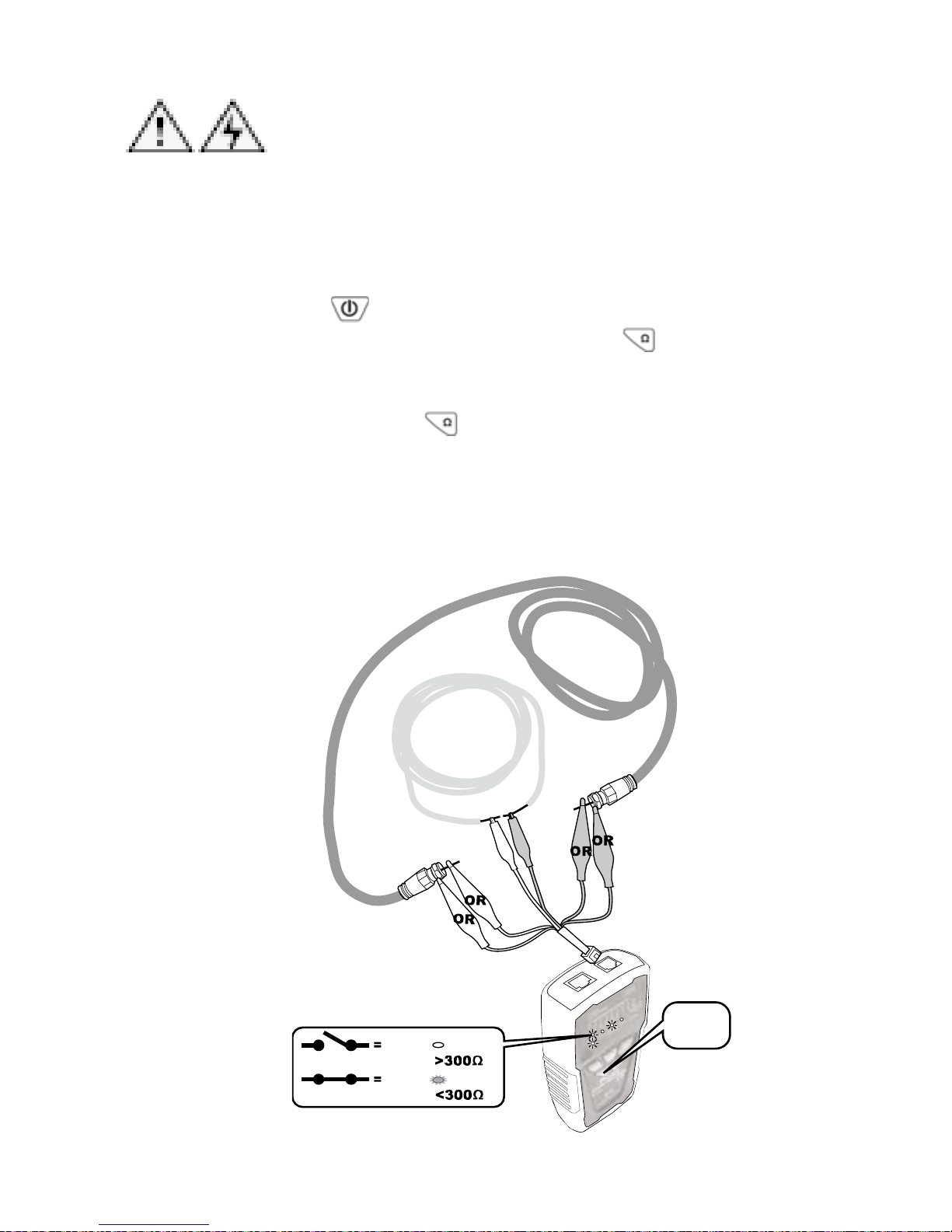
To validate cable shield during cable map tests, do the following as
shown in Figure 9:
1. Connect the Transmitter to the circuit as shown in
Figure 8. Connect the test leads to the coaxial cable to
be tested.
2. Push “
” button to turn on the power, “POWER/ BAT
LOW” indicator will light up. Push “
” button on
transmitter for short/ open function, the green LED
indicator lights up and the short/ open testing is
working. Push “
” again, the green LED lights off and
the product is standby for next operation.
3. When “SHORT” red LED indicator lights up, the cable
is connected. (the resistance of cable is less than
300Ω). If the indicator is off, the cable is short or
resistance of the cable is over 300Ω .
Testing for
continuity
Validating the
cable ’s shield
push
Ω
OPEN
SHORT
Open : Resistance
Short : Resi stan ce
No light
RED
19
Figure 9 Coaxial Cable & Continuity Test
Page 21
Validati
ng Telephone Service and Polarity:
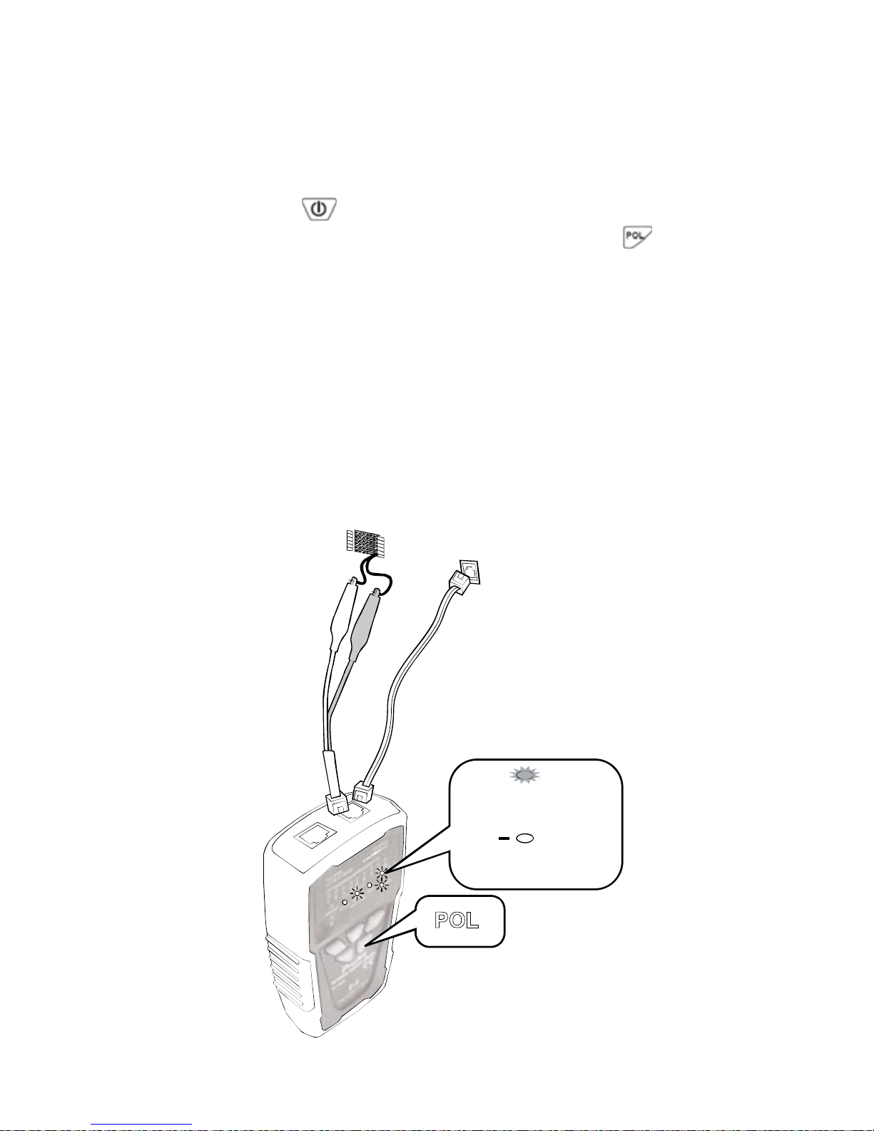
Please follow the following steps to check the polarity of telephone
lines:
1. Connect the Transmitter to the circuit as shown in
Figure 9. Connect the test leads to the telephone
punch-down blocks, RJ11, and RJ45 jacks.
2. Push
button to turn on the power, “POWER/ BAT
LOW” indicator will light up. Then push
to operate
the polarity indication feature and the LED indicator will
light up. Push the button again to get the product back
to standby status.
3. 「POL-/G,POL+/R」LED indicator is dual color
(Red/ Green). The LED indicator of the Transmitter
indicates the status as below:
• Red light:Red test lead at positive (+) polarity;
Black test lead at negative (-) polarity.
• Green light:Red test lead at negative (-)
polarity;Black test lead at positive (+) polarity.
• No Light:Non service or line fault.
POL
POL
RED
Green
Red test lead (+ Polarity)
Black test lead(- Polarity)
Red test lead (- Polarity)
Black test lead(+ Polarity)
+
POL
RJ11 Jack
Telephone
Block
20
Figure 10
Validating Telephone Service and Polarity
Page 22
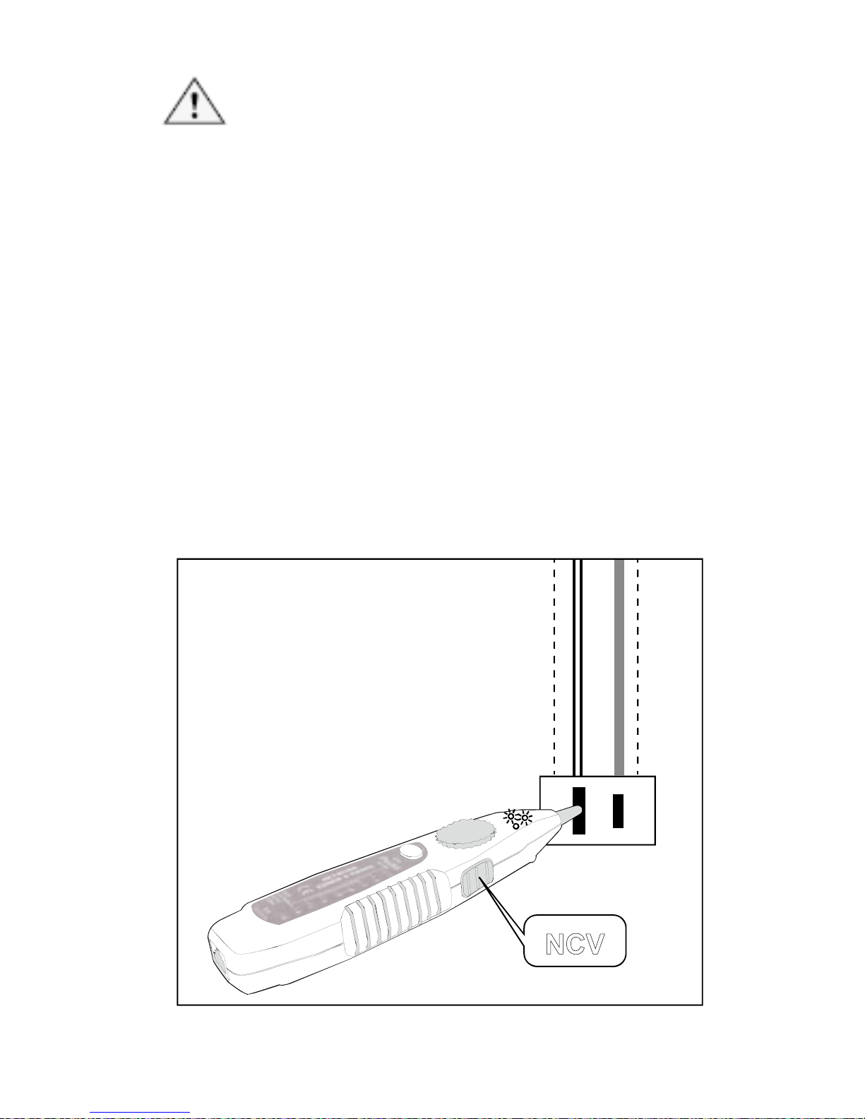
NCV (N
on-Contact Voltage) Testing:
Caution
• The feature can be used before locating, isolating,
cable mapping to identify if the tested cable is with
AC voltage. It can not only help to ensure the safety
of user and avoid possible electric shock or personal
injury, but also protect the product from being
damaged by AC power.
1. Per Figure 11, turn the switch to “NCV”, the function is
started when the power indication is on.
2. When doing the NCV testing, place the probe of MT-7028
receiver to the tested cable, the NCV indicator twinkled fast
and the buzzer sounded it means the tested objective has
AC 90~1000V. If the indicator did not come on and no
buzzer sounded, it means the tested objective has AC
power less than 90V or there is no AC power on it.
AC
Socket
NCV
Figure 11 Non Contact Voltage Test
21
Page 23
Batter
y Life and Replacement
Caution
To avoid unreliab
le test results, replace the battery as soon
as the low battery indication appears.
Warning
To avoid possible electric shock or personal injury, turn off
the Transmitter or Receiver and disconnect all test leads
before replacing the battery.
Battery Status: ”BAT LOW” LED lights up on the Transmitter
indicates the voltage is under 6.5V for powering up the device.
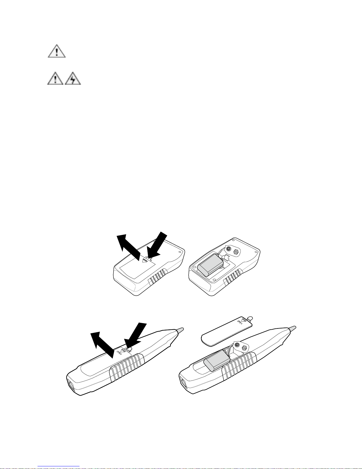
To replace the battery, do the following (Fig 12):
1. Turn off the Transmitter or Receiver and disconnect all
test leads before replacing the battery.
2. Properly installed in the case to power the Transmitter
and Receiver.
3. Use only a 9V (6FF22) battery.
O
P
E
N
Figure 12 Replacement of the Battery
22
Page 24
Mainte
nance & Trouble shooting:
Warning
Turn off the Transmitter or Receiver and disconnect all test
s before replacing the battery. lead
Caution
To avoid damagi
ng the case, do not use solvents or
abrasive cleansers. Clean the case with a soft cloth
dampened with water or a mild soap solution.
Trouble shooting
Possible Problems Trouble shooting
1. Shortage of battery power: Check the
batter on both transmitter and receiver.
If the battery voltage is less than 6.5V,
please replace with a new battery.
2. Make sure the switch position on
receiver is “OFF” or “LED”. The SCAN
function will not work if the switch is at
“NCV” position.
The signal from
transmitter can not be
detected by receiver
3. Device damaged: please return the
product to the place you purchased the
product for maintenance.
No signal received from
transmitter on Live
telecommunication
device testing
There might be conflict between the signal
from telephone office and the signal from
transmitter. Please turn off the telephone
exchange device.
LED indicator broken: please return the
product to the place you purchased the
aintenance. product for m
Incorrect cable mapping
result
Improper connection of networking or
telephone cables: please reconnect the
cables toRJ45/ RJ11 compatible
connectors.
Others
Device damaged: please return the
product to the place you purchased the
product for maintenance.
23
 Loading...