

Page 1
MICROPROCESSOR BASED REVERSE POWER RELAY
FEATURES
Micro controller based, hence accurate and precise.
Protection of generator / prime movers against reverse power
Visual indication of power, pick-up and relay tripping.
Display of reverse power on the LCD.
Continuous display of sensing voltage, current, frequency and power factor with lead/lag
indication.
Wide Auxiliary voltage range from 85 – 275 VAC/DC.
Cost effective and highly reliable compact design.
Test Facility, allowing the user to check the NO and NC contacts of the relay.
SPECIFICATION
Rated Current
Trip Level
5Amps
4 % – 20 % In in steps of 1%
Delay
0 – 20 Sec in steps of 0.1 Sec
Sensing Voltage Range
50 – 500 V
Frequency Range
40 – 60 Hz
Accuracy
± 5 %
Repeatability
± 1 %
Operating Voltage
85 – 275 V AC/DC
Enclosure Dimensions
144 * 144 * 105 mm
APPLICATIONS
The reverse power relay prevents the generator from running as a motor, thus protecting the
prime mover (eg. A diesel engine) by tripping the generator breaker, and at the same time
avoiding overload on the remaining generators.
Page 2
FUNCTION
The reverse power relay measures the phase voltage (L – N operation) and the current of that
phase through the current transducer. It calculates I Cos ө representing the active power. If the
active power becomes negative and exceeds the preset level (4 – 20 %) the pickup, RED LED
will blink and the delay timer will start. After the preset time (0 – 20 sec) the relay will trip and
the RED LED will glow. The reverse power (-I * Cos ө) is displayed on the LCD. During the
healthy condition the GREEN LED glows,
SETTING PROCEDURE
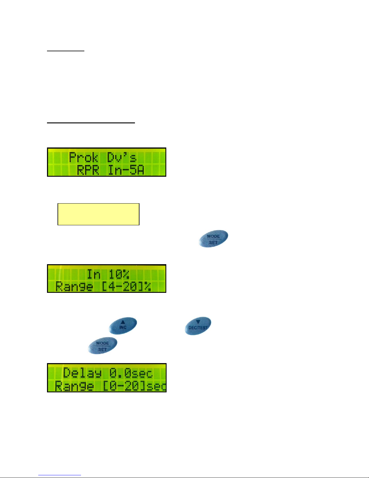
Connect the auxiliary supply, sensing voltage and current to the reverse power relay.
The display shows
After few seconds, the display shows the sensing voltage, current, frequency and power factor
(only if both voltage & load current above 100ma available at the sensing input).
To enter the setting mode, press the mode/set key . At first display comes for setting
of reverse current. The display shows
Range is from 4% to 20% at steps of 1%
Press the increment and decrement key to make the desired setting.
Press the set key to store the value. The display changes as shown
Range is from 0 sec to 20 sec at steps of 0.1 sec
V=240V F=49.9Hz
I=5.00A PF+0.95
Page 3
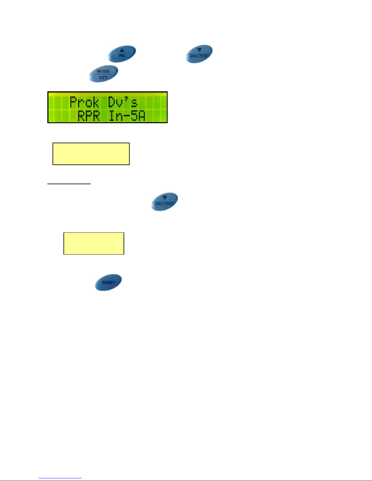
Press the increment and decrement key to make the desired setting.
Press the set key to store the value. The display shows
For a while and then displays the sensing voltage, current, frequency and power factor.
Relay Testing
Press and hold the decrement/test key for 3 seconds. The relay goes into the test
mode. The display shows
At first the relay trips, then the GREEN LED switches OFF and at last the RED LED switches
ON, with a definite time gap of 2 seconds. It goes to LOCK MODE. The Relay Test blinks till
the RESET key is pressed.
Relay Test
--------------------
V=240V F=49.9Hz
I=5.00A PF+0.95
Page 4
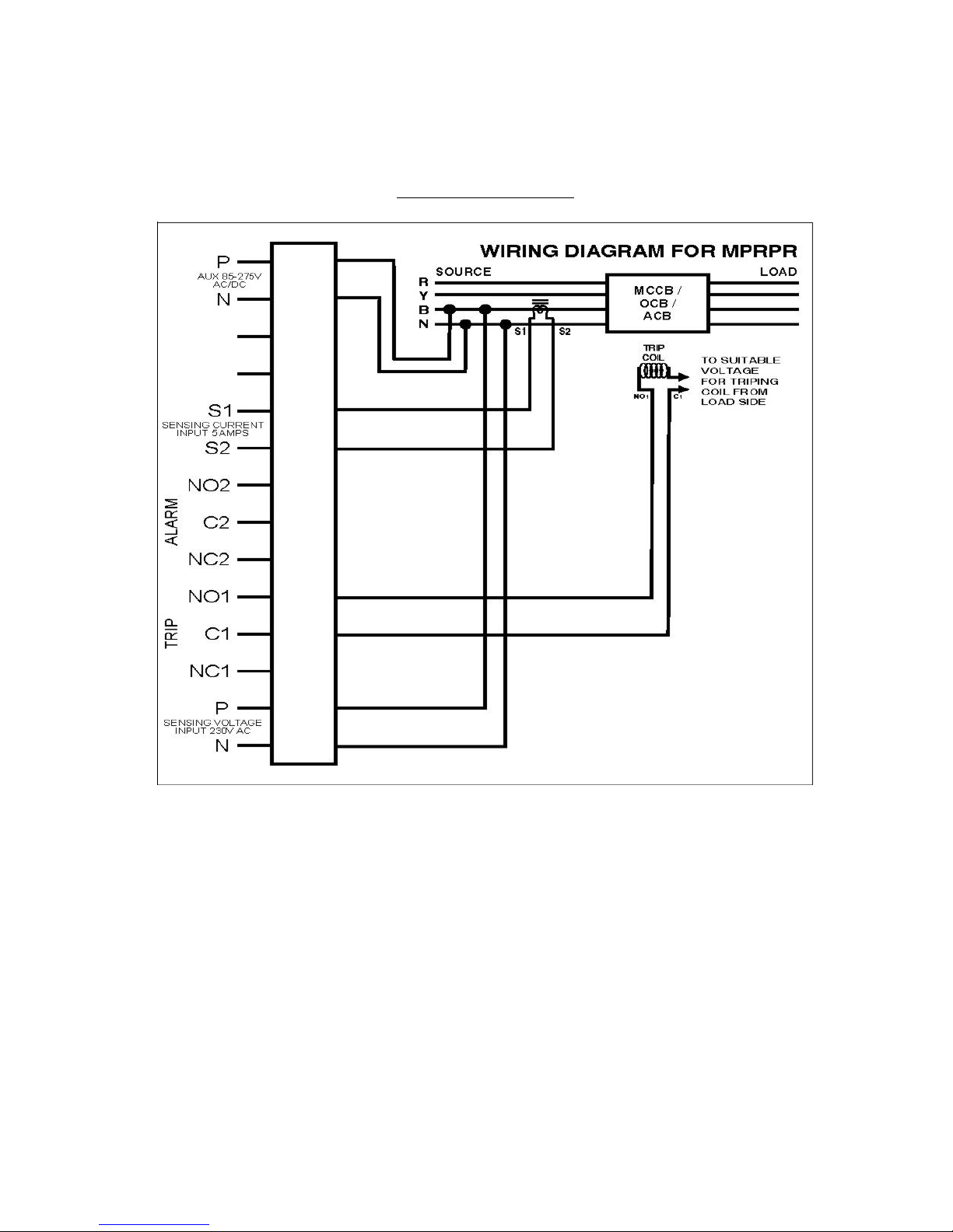
WIRING DIAGRAM
Page 5

 Loading...