

Page 1

projectiondesign as
projectiondesign as
user’s guide
SXGA+
HD720
HD1080
dnx
COMPATIBLE
user’s guide
Benutzer Handbuch
guide d’utilisateur
guía del usario
manuale d’uso
bruksanvisning
Page 2

TABLE OF CONTENTS
english
INTRODUCTION ........................................................................4
SAFETY & WARNINGS ...................................................................6
WARNING SYMBOLS ON THE PROJECTOR ...............................................12
SUPPLIED MATERIAL ...................................................................14
OPTIONAL LENSES ....................................................................16
OVERVIEW ...........................................................................18
KEYPAD ............................................................................20
INDICATORS .........................................................................24
REMOTE CONTROL ....................................................................26
CONNECTOR PANEL ...................................................................32
SET UP ..............................................................................34
SET UP VIDEO ......................................................................34
SETUP COMPUTER ..................................................................34
INITIAL SET UP ........................................................................36
LAMP OPERATION .....................................................................38
PIN CODE ...........................................................................38
CEILING MOUNT ......................................................................40
CEILING MOUNT ......................................................................42
CEILING MOUNT COVER ..............................................................42
USING THE PROJECTOR ................................................................44
SWITCHING ON AND OFF .............................................................44
RS 232 AND LAN CONTROL ...........................................................46
TIMER ............................................................................48
IMAGE CALIBRATION AND CORRECTION .................................................50
MENU SYSTEM .......................................................................52
OVERVIEW .........................................................................52
TOP MENU .........................................................................52
NAVIGATING THE MENU SYSTEM .......................................................52
PICTURE MENU .....................................................................54
RealColor SUB MENU .................................................................58
ADVANCED SUB MENU ...............................................................60
ENHANCEMENTS SUB MENU ..........................................................62
INSTALLATION SUB MENU .............................................................64
LAMP SUB MENU ...................................................................66
LAMP MODE SUB MENU ..............................................................66
SETTINGS SUB MENU ................................................................68
PROFILES SUB MENU ................................................................72
LANGUAGES SUB MENU ..............................................................72
STATUS SUB MENU ..................................................................74
TROUBLE SHOOTING ..................................................................76
NO IMAGE .........................................................................76
DARK IMAGE .......................................................................76
FLICKERING IMAGE ..................................................................76
UNSHARP IMAGE ....................................................................76
MAINTENANCE .......................................................................78
HEAVY DUTY AND CONTINOUS USE .....................................................78
SERVICE INFORMATION ................................................................78
LAMP CHANGE .......................................................................80
TECHNICAL DATA .....................................................................82
CONNECTORS ......................................................................82
IMAGE SIZES .......................................................................84
DECLARATIONS .......................................................................88
2
Page 3

INTRODUCTION
This digital projector is designed with the latest state-of-the-art technologies in illumination,
imaging, optics, electronics, thermal and industrial design in order to serve traditional as well as
novel imaging applications across a variety of markets, offering features such as:
Full HD 1080p, 720p, or sxga+ resolution single chip DLP® technology•
Patented Dual Architecture illumination system and optics•
RealColor advanced colour management suite•
Fail safe, how swap Dual Lamp architecture•
Dual optomechanical IRIS for customizable brightness and contrast•
Full powered horizontal and vertical lens shift, allows direct stacking •
Full 10-bit colour resolution for minimised artefacting and high accuracy•
BrilliantColor™ technology with six-colour processing for accurate colours•
Elevated contrast levels for unmatched image dynamics•
High brightness for large screen applications•
Range of application specific colour wheel options•
Wide range of projection lenses•
Highly versatile colour management and calibration options•
Built-in real time clock for timed operations•
Pixelworks DNX™ technology video de-interlacing and processing•
Economy mode for reduced power consumption and prolonged lamp life•
Small and ergonomic footprint, with low weight•
Direct view status monitor and lamp function indicators•
Six video and graphics inputs for virtually any video and data source•
HDMI ver. 1.3a•
LAN, RS232 and USB ports for control and monitoring•
The specifications and functionality of this projector may change without prior notice.
english
4
Page 4

SAFETY & WARNINGS
This user guide contains important information about safety precautions and the set-up and use of
the projector. Please read the manual carefully before you operate the projector.
english
SAFETY
This device complies with relevant safety regulations for data processing equipment for use in an
office environment. Before using the projector for the first time, please read the safety instructions
thoroughly.
WARNING
Use only the cables and cords supplied with the projector or original replacement cables. Using
other cables or cords may lead to malfunction and permanent damage of the unit.
Always use 3-prong / grounded power cord to ensure proper grounding of the unit. Never use
2-prong power cords, as this is dangerous and could lead to electrical shock.
Never open the unit. The projector contains no user serviceable parts. Refer all repairs to qualified
personnel only. Make sure that no objects enter into the vents and openings of the set.
Do not spill any liquids on the projector or into the vents or openings of the unit.
Always remove lens cap before switching on the projector. If the lens cap is not removed, it may
melt due to the high energy light emitted through the lens. Melting the lens cap may permanently
damage the surface of the projection lens.
Do not look into the projection lens when the projector is switched on. The strong light may
permanently damage sight. Do not look into the laser beam when activated on the remote control.
Laser light may permanently damage sight.
Do not point laser beam on people.
Only place the projector on a stable surface, or mount it securely using an approved ceiling-mount.
Do not drop the projector.
Always operate the projector horizontally, within the range of the adjustable rear feet. Operating the
unit in other positions may reduce lamp life significantly, and may lead to overheating, resulting in
malfunctioning.
Always allow ample airflow through the projector. Never block any of the air vents. Never cover the
unit in any way while running. Allow for sufficient distance to walls and ceilings to avoid overheating.
Minimum safety distance to any side of the unit is 50 cm / 20” in any direction.
CAUTION! Hot air is exhausted from the rear vent. Do not place objects that are sensitive
to heat nearer than 50cm / 20” to the exhaust vent.
The projector is designed for indoor use only. Never operate the unit outdoors.
6
Page 5

SAFETY & WARNINGS
Do not operate the projector outside its temperature and humidity specifications, as this may result
in overheating and malfunctioning.
Only connect the projector to signal sources and voltages as described in the technical
specification. Connecting to unspecified signal sources or voltages may lead to malfunction and
permanent damage of the unit.
Allow the unit to cool down for 60 minutes before lamp change.
INFORMATION AND WARNING ABOUT POTENTIAL HEALTH ISSUES RELATED TO
MERCURY VAPOR.
This projector uses a very powerful UHP™ lamp for illumination to produce an extremely bright
image.
This technology is similar to other high-pressure discharge lamps that are extensively used in cars,
street lights and other lighting appliances today. These lamps, like fluorescent lighting, contain small
amounts of mercury. The amount of mercury present in a lamp is far below the limits of danger set
by the authorities. It is very important that lamps containing mercur y are treated properly to minimize
potential health hazards.
The UHP™ lamp, like any other high brightness projector lamp, is under high-pressure when
operating. While the lamp and the projector are carefully designed to minimize the probability of
lamp rupture, the lamp may break while operating and small amounts of mercury vapor may be
emitted from the projector. The probability of rupture increases when the lamp reaches its nominal
life. It is therefore highly recommended that the lamp is replaced when the rated lifetime is reached.
As a general precaution, secure good ventilation in the room when operating the projector. If lamp
rupture occurs, evacuate the room and secure good ventilation. Children and pregnant women in
particular should leave the room.
When replacing a worn lamp, dispose of the used lamp carefully by proper recycling.
Mercury is a naturally occurring, stable metallic element that may pose a safety risk to people under
certain conditions. According to the Public Health Statement for Mercur y published by the Agency
for Toxic Substances and Disease Registry (“ATSDR”, part of the United States Public Health
Service), the brain, central nervous system and kidneys are sensitive to the effects of mercury,
and permanent damage can occur at sufficiently high levels of exposure. Acute exposure to high
concentrations of mercury vapor can cause conditions such as lung and airway irritation, tightness
in the chest, a burning sensation in the lungs, coughing, nausea, vomiting and diarrhea. Children
and fetuses are particularly sensitive to the harmful effects of metallic mercury to the nervous
system.
Seek medical attention if any of the above symptoms are experienced or if other unusual conditions
are experienced following lamp rupture.
english
8
Page 6

SAFETY & WARNINGS
english
WEEE INFORMATION
This product conforms to all requirements of the EU Directive on waste
electrical and electronic equipment (WEEE). This product shall be
recycled properly. It can be disassembled to facilitate proper recycling
of it’s individual parts. This product is using projection lamps that shall
be recycled properly. Consult your dealer or relevant public authority
regarding drop-off points for collection of WEEE.
WARNING
This product contains chemicals, including lead, known to the State of
California to cause birth defects or other reproductive harm. Recycle
properly, do not dispose of in ordinary waste!
REMOTE CONTROL WARNING
Laser radiation class II product; wavelength 670nm; maximum output
1mW.
Remote control complies with applicable requirements of 21 CFR
1040.10 and 1040.11.
Remote control complies with applicable requirements of EN 60 825-1:
1994 + A11
10
Page 7
SAFETY & WARNINGS
english
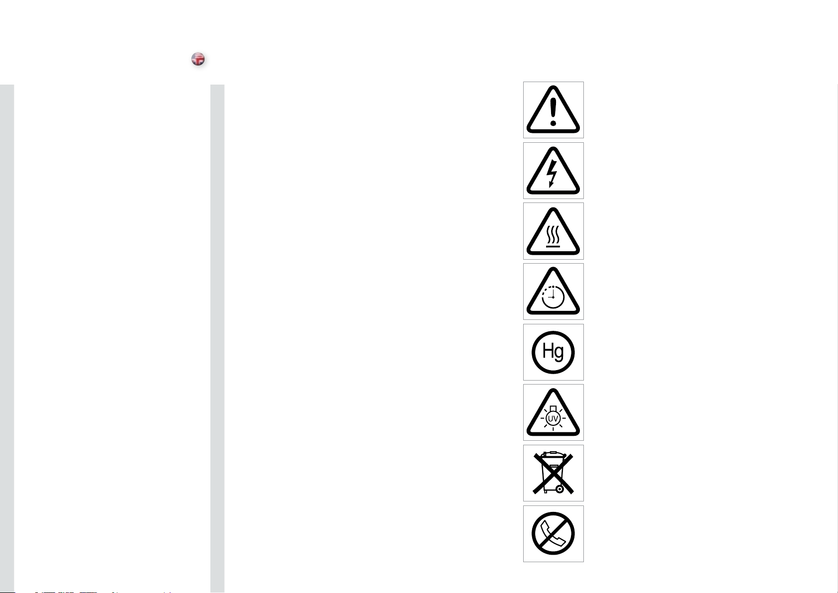
WARNING SYMBOLS ON THE PROJECTOR
READ USER GUIDE
Attention! Read the user guide for further information!
DANGEROUS VOLTAGE
Danger! High voltage inside the product!
HOT
Warning! Hot surfaces!
WAIT
Warning! Wait until cooled down!
MERCURY
Warning! Lamp contains mercury! Recycle properly, do not dispose of
in ordinary waste!
UV
Warning! UV radiation inside the product!
RECYCLE
Warning! Recycle properly, do not dispose of in ordinary waste!
NO TELEPHONE
Warning! Do not connect to telephone lines!
12
Page 8
SUPPLIED MATERIAL
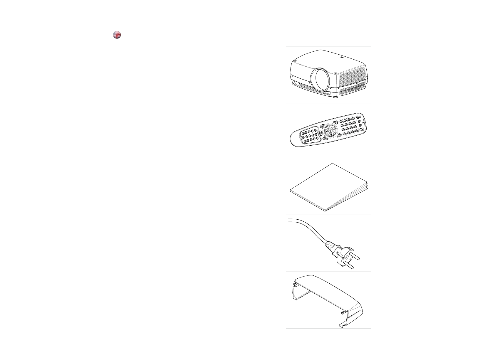
Projector without lens
Lens supplied separately
Remote control with batteries
Quick Start Guide
english
Power Cord
(country dependent)
Ceiling mount cable cover
Before Set up and Use
Unpack the supplied parts and familiarise yourself with the
various components.
14
Page 9
OPTIONAL LENSES
A range of fixed and zoom lenses is available to cover most
applications, both front and rear. The lenses are powered and fitted
with a bayonet mount for ease of installation.
english
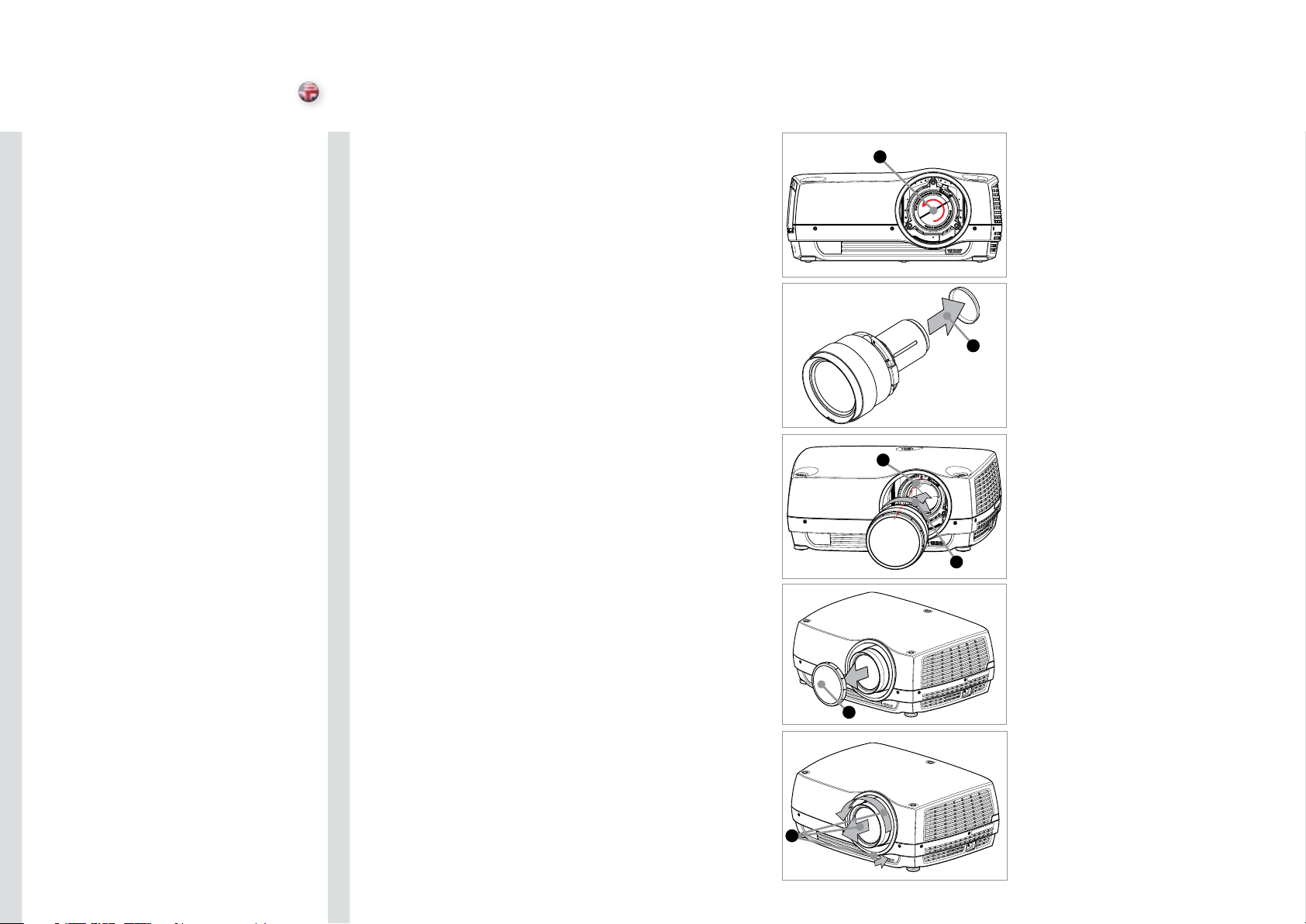
Switch off all equipment before setting-up for proper
function.
When mounting and changing lenses, be aware that the optical
system is exposed to dust and foreign particles as long as the lens is
not attached to the system. Do not leave the lens mount open longer
than necessary to change lens. If a lens is not mounted, always insert
the protection lid to avoid dust and foreign particles entering the
internal optics.
Never run the projector without lens mounted.
A
Remove the protection lid from the bayonet mount by turning the A
knob anti-clockwise.
Remove the rear lens cap. B
Attach the projection lens using the bayonet mount, observing the C
red insertion marks.
Turn the lens firmly clockwise until it stops with a click.D
Remove the lens cap from the projection lens. If you switch the E
projector on with the lens cap in place, the lens cap may melt,
damaging not only the lens cap, but also the projection lens and
surrounding parts.
To change lens, first remove the curret lens by pushing the release F
button and twisting the lens counter-clockwise until it comes loose.
Pull the lens out.
Insert the new lens as described above.
B
C
D
E
16
F
Page 10
OVERVIEW
english
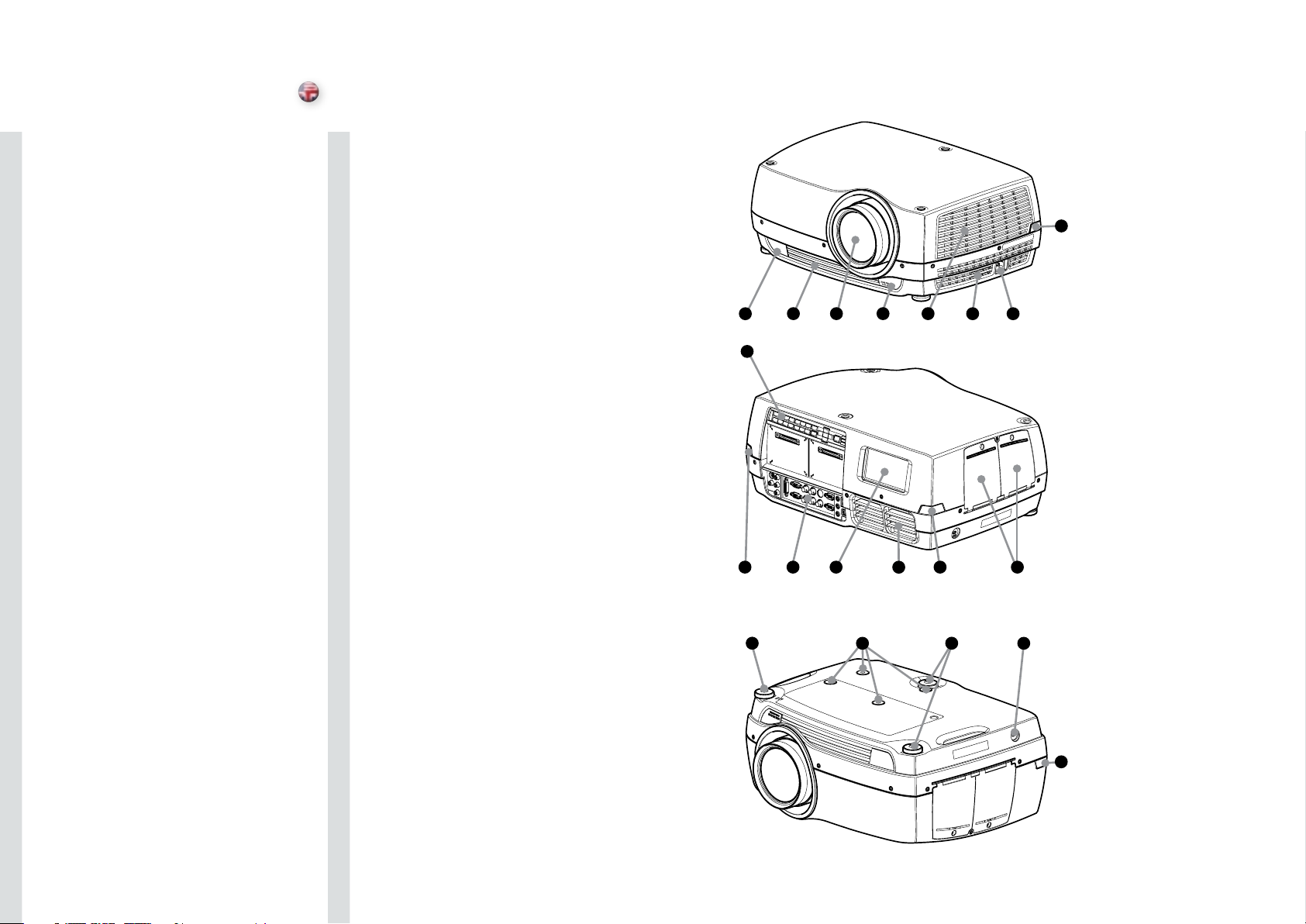
LensA
IR sensorB
VentilationC
Lens releaseD
Power connector E
Keypad F
Connector panelG
LCDH
Lamp lidsI
Adjustable feetJ
Security lockK
Ceiling mountL
B
B G H
C A D C
F
C
B I
C E
B
18
J
L
J
K
B
Page 11
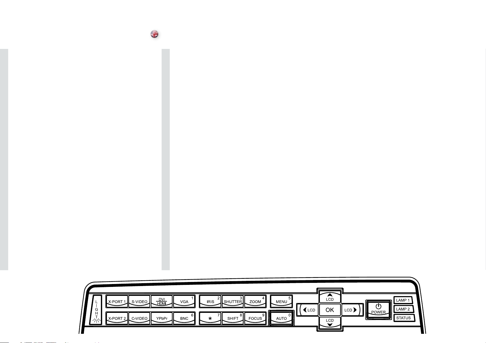
KEYPAD
The keypad is illuminated for operation in dark environments. Available functions are illuminated
in yellow while selected (active) functions are illuminated in green. Functions that are not
available are not illuminated.
In addition to the various functions, 10 keys are numbered 0-9. These keys are used for PIN
code and other numeric functions as applicable.
english
POWER
Switches the projector between on and standby modes. Press firmly (1 sec) to switch on. Press
firmly (1 sec) twice to switch off.
AUTO
Adjusting the projector to display a correct image, including position, width, height, contrast,
brightness and overall stability.
MENU
Activates the menu system. Use the four arrow keys to navigate and «OK» to activate.
ARROW KEYS
Use the arrow keys to navigate the menu system or to control lens and LCD functions.
OK
Confirm menu option when menu system is activated.
ZOOM
Select ZOOM, then use arrow keys to zoom in or out.
FOCUS
Select FOCUS, then arrow keys to focus the image
SHIFT
Select SHIFT, then the arrow keys to shift the image up, down or sideways.
IRIS
Select IRIS, then arrow keys to adjust to desired combination of brightness and contrast.
SHUTTER
Press SHUTTER to stop the projected image completely.
20
20
Page 12
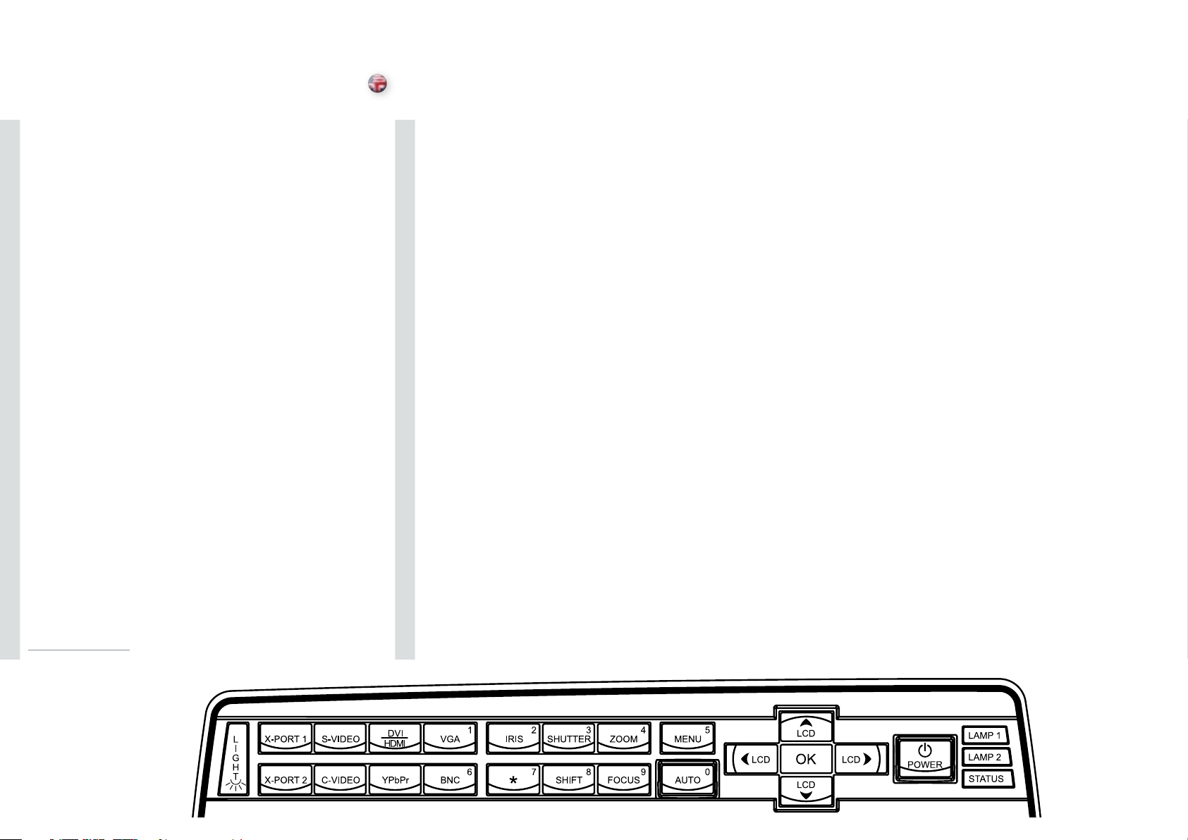
KEYPAD
english
VGA
Selects the VGA input as active source.
DVI/HDMI
Activates the DVI-D input.
BNC
Selects BNC as source.
YPbPr
Activates the component video input.
S-VIDEO
Selects super video as active source.
C-VIDEO
Activates the composite video input.
X-PORT 1
Activates the X-PORT 1. This key is enabled by the X-PORT 1 device as and when attached.
Functionality depends on the actual device connected (see separate user guide for this device).
X-PORT 2
Activates the X-PORT 2. This key is enabled by the X-PORT 2 device as and when attached.
Functionality depends on the actual device connected (see separate user guide for this device).
1
1
LIGHT
This key switches the illumination of the connector area on and off.
INDICATORS
The LAMP 1, LAMP 2 and STATUS indicators are not keys, so please do not push.
1 Not applicable to all models.
22
Page 13
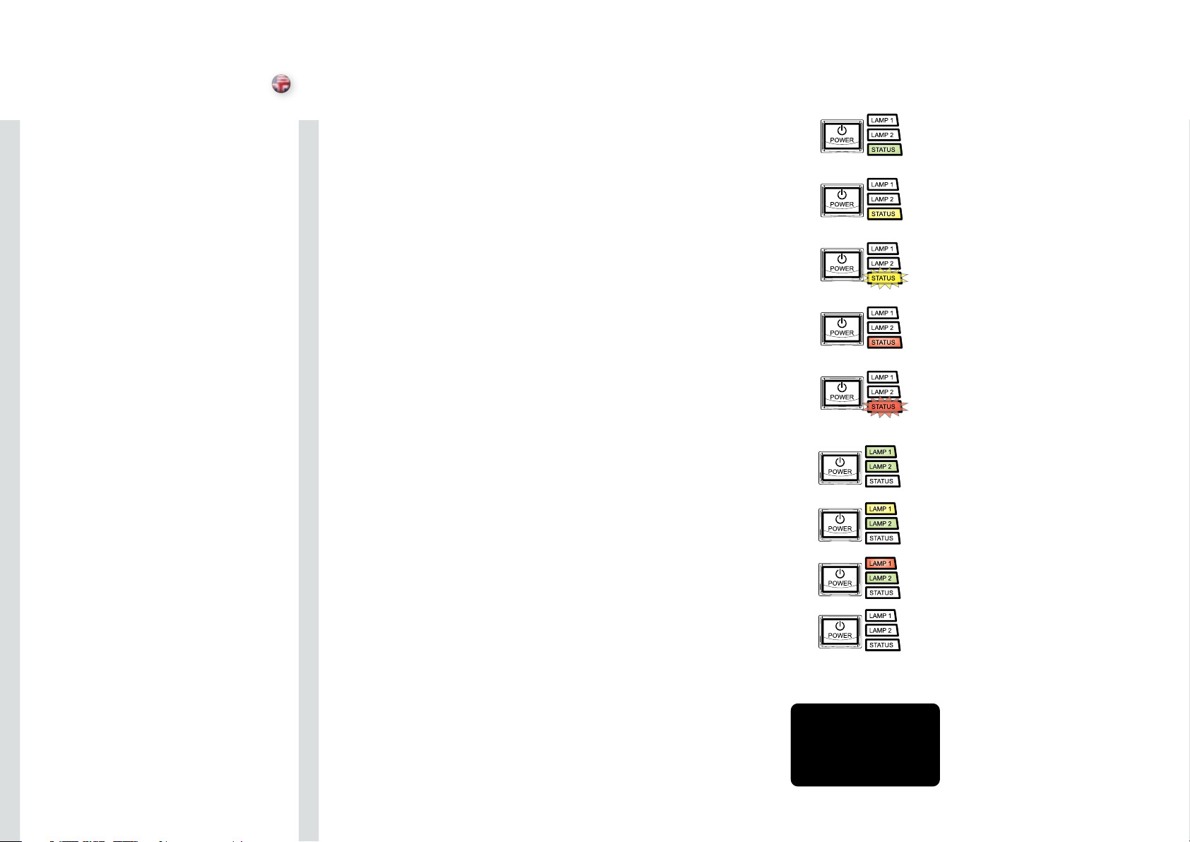
INDICATORS
english
STATUS
Indicates the overall system status by green, yellow and red colors.
PERMANENT GREEN LIGHT
The projector is turned on and in normal operation.
PERMANENT YELLOW LIGHT
The unit is in standby mode; no source(s) connected, or the source(s)
connected are inactive or switched off, thereby activating the powersave function (DPMS). You may enable or disable the power save
function in the SET UP sub menu, DPMS on or off.
FLASHING YELLOW LIGHT
Please wait. The yellow light will flash a period after power cord is
connected (10-15 sec.), and a period after going to standby mode
while lamp is cooling down (approximately 45 sec.). The projector may
not be turned on again until the light has turned to permanent yellow.
FLASHING RED LIGHT
Projector is overheated. Turn off immediately! Check if air inlets are
covered or if ambient temperature is outside specifications. The
projector can not be restarted unless the power cord is disconnected
and reconnected again. If the projector continues to flash red, you will
need to return the unit for service.
LAMP 1, LAMP 2
Indicate the status of each lamp by green and red colors.
PERMANENT GREEN LIGHT
The lamp is on and in normal operation.
PERMANENT YELLOW
The lamp is ready and in standby mode
FLASHING YELLOW
Please wait. Lamp is cooling down.
PERMANENT RED LIGHT
Lamp life has expired or lamp is not igniting or lamp door is open.
Please change projection lamp immediately. Failing to change lamp
may lead to lamp explosion.
NO LIGHT
No lamp inserted / connected
LCD
The projector is fitted with a backlit LCD screen that reports system
status. You can navigate the LCD screen by using the arrow keys on
the keypad.
24
LCD
Page 14
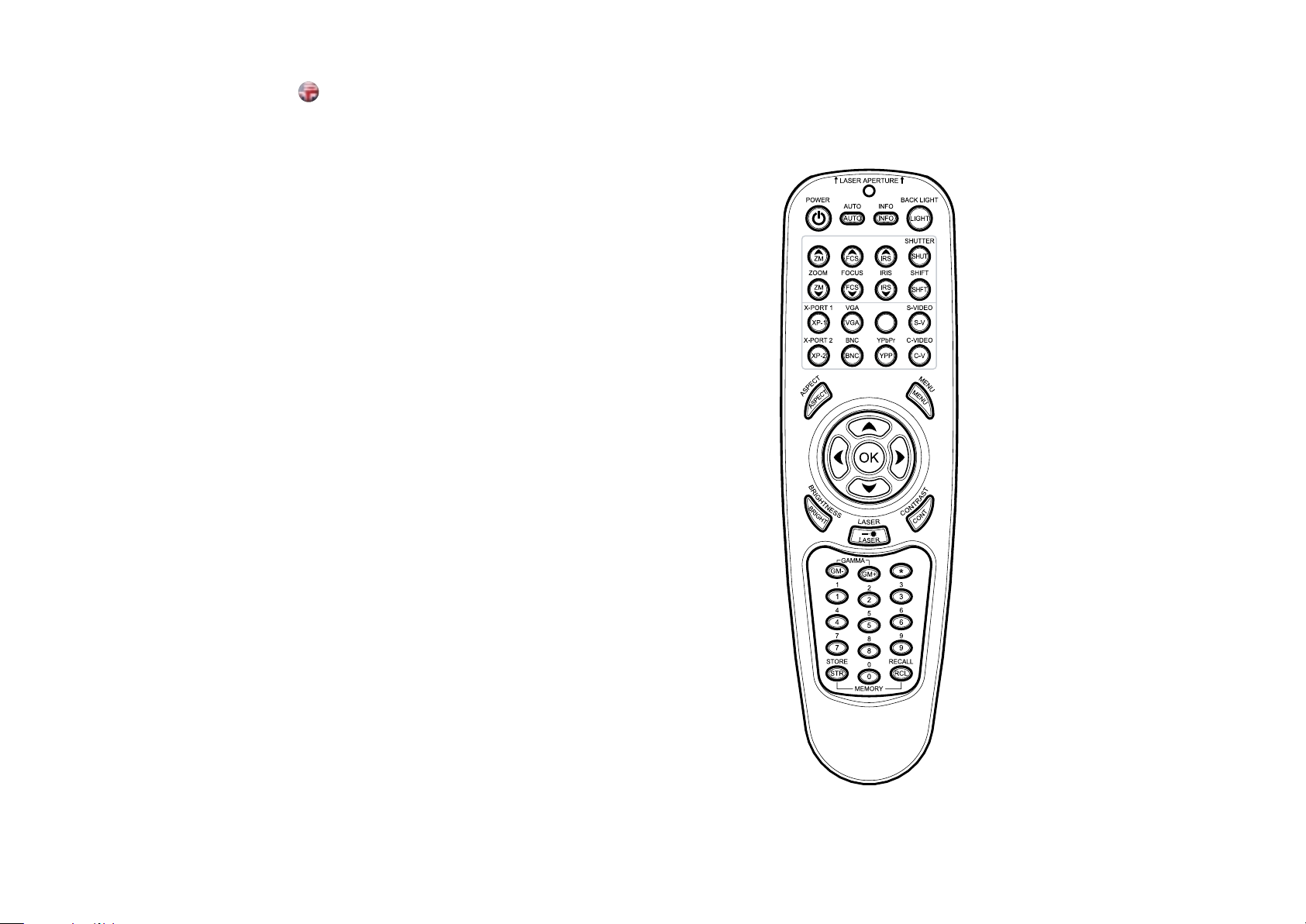
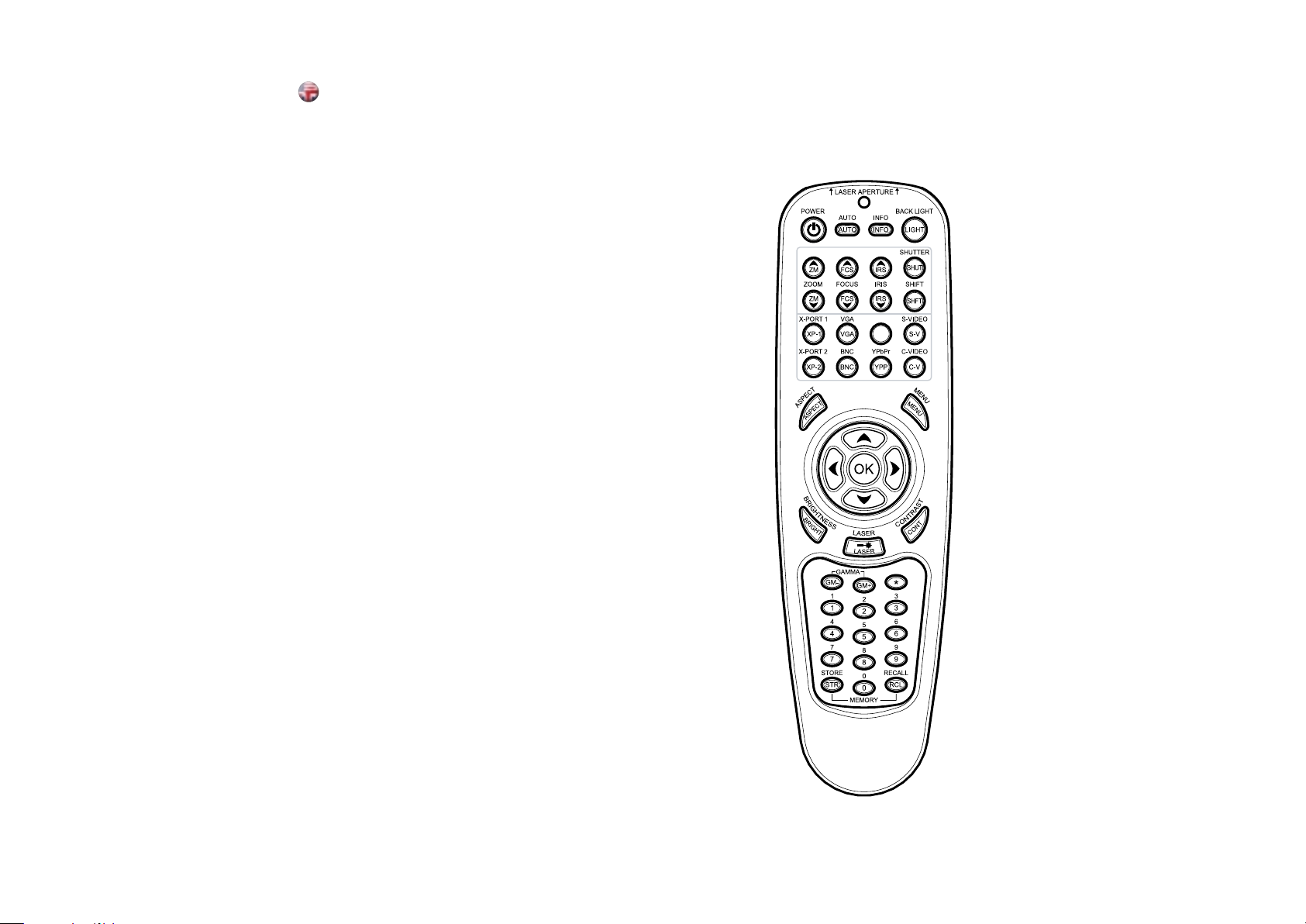
REMOTE CONTROL
The remote control allows flexible access to the projector settings,
either through direct keys, or through the menu system. The remote
control is backlit for use in dark environments. It also has a data-jack
that allows for wired connection to the projector. When the wire is
connected, the IR (infra-red) beam and internal batteries are switched
off.
The remote control can be operated either in ‘broadcast mode’, or
‘individual mode’. When several projectors are in use in an installation,
individual control may be convenient. Individual control is available
either by wired remote control, using the data-jack, or by using an
individual number code. For individual control, first set the individual
RC ID code using the projector menu system, see the SETTINGS sub
menu. Then, to select a specific projector to control, first press the
‘*’ button in the lower keypad area, then the code as set in the target
projector. A code can be in the range ‘0’..’255’. ‘0’ is reserved for
broadcast. To select another target, repeat the process by pressing ‘*’
and a new code. To exit individual control, press ‘*’’*’ twice or press
‘*’ and ‘0’.
english
DVI/HDMI
D/H
POWER
Switches the projector between on and standby modes.
AUTO
Adjusting the projector to display a correct image, including position,
width, height and overall stability.
INFO
Displays source and projector status on screen.
BACKLIGHT
Switches the backlight on and off. The backlight will switch off
automatically after ten seconds.
BRIGHT
Adjusts image brightness.
CONTRAST
Adjusts image contrast.
COLOR
Adjusts color saturation of the image.
26
Page 15
REMOTE CONTROL
english
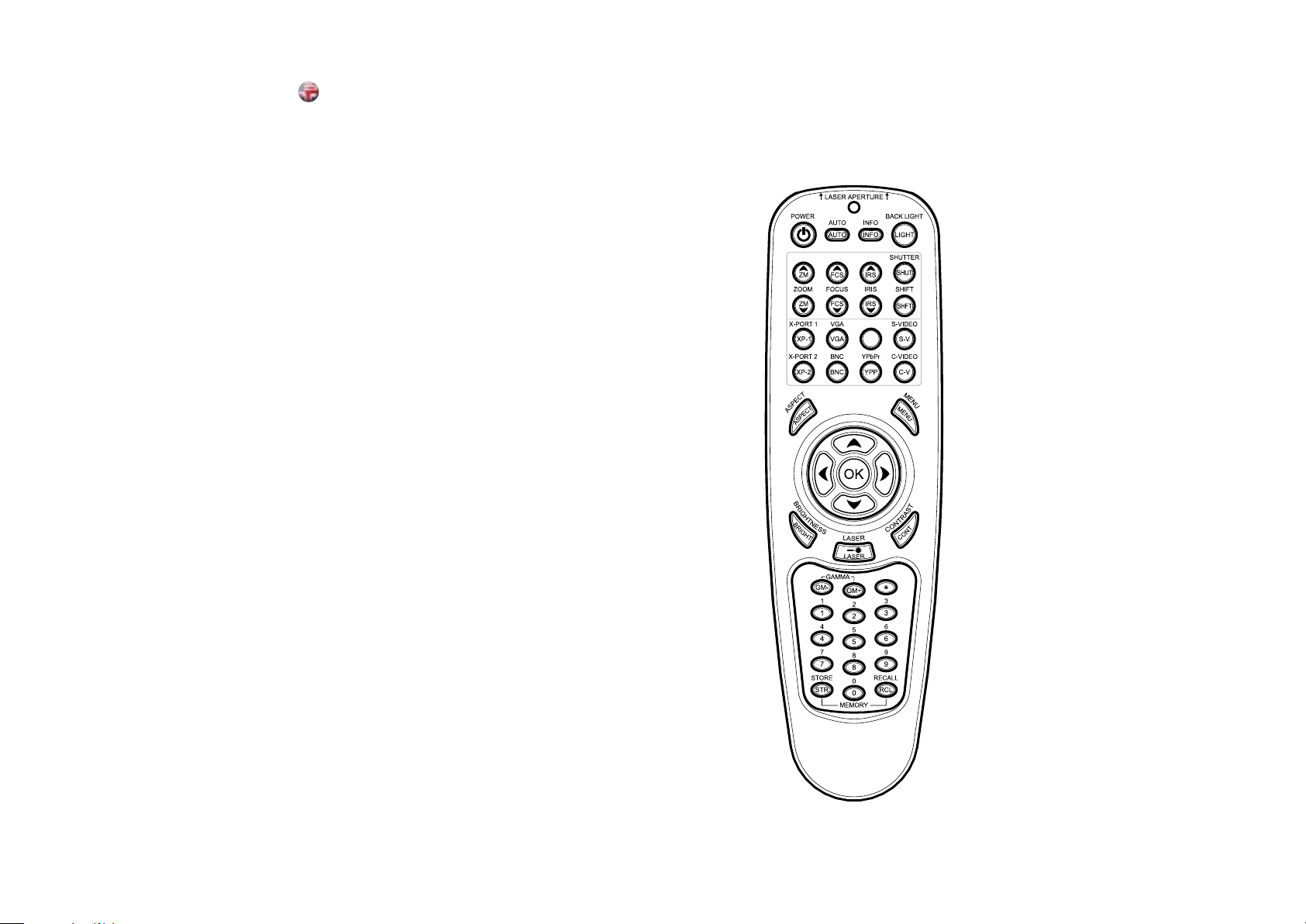
C-VIDEO
Selects the composite video input as signal source.
S-VIDEO
Selects the super video input as signal source.
YPbPr
Selects component video input.
DVI/HDMI
Selects the DVI or HDMI input.
VGA
Selects the VGA input.
BLACK
Toggles the projected image on and off. The lamp is not shut off.
STILL
Toggle function, locking the projected image on and off.
TIME
Displays date and time. Set the date and time in the MENU system,
SETTINGS sub menu.
KEYSTONE
Press KEYSTONE to activate the electronic trapezoid correction,
adjust with arrow keys.
ASPECT
Cycles through the aspect ratios available with the current source.
MENU
Toggles the menu system on and off, and navigates one step
backward in the menu system.
ARROW KEYS
Use the arrow keys to navigate in the menu system and other
adjustments.
OK
Press OK to confirm selected option in menu.
LASER
Activates the built-in laser pointer. CAUTION! Do not point laser beam
at people. Do not stare into laser beam.
DVI/HDMI
D/H
28
Page 16
REMOTE CONTROL
english
GAMMA
Press GM+ or GM- to select between gamma settings.
STORE
Press STORE, then one digit 0-9, to store user setting in memory.
RECALL
Press RECALL, then one digit 0-9, to recall user setting from memory.
0-9
Used for various numeric functions such as PIN code and user
memory.
* (ASTERISK)
Used for RC ID control. See the explanation above.
DVI/HDMI
D/H
30
Page 17

CONNECTOR PANEL
english
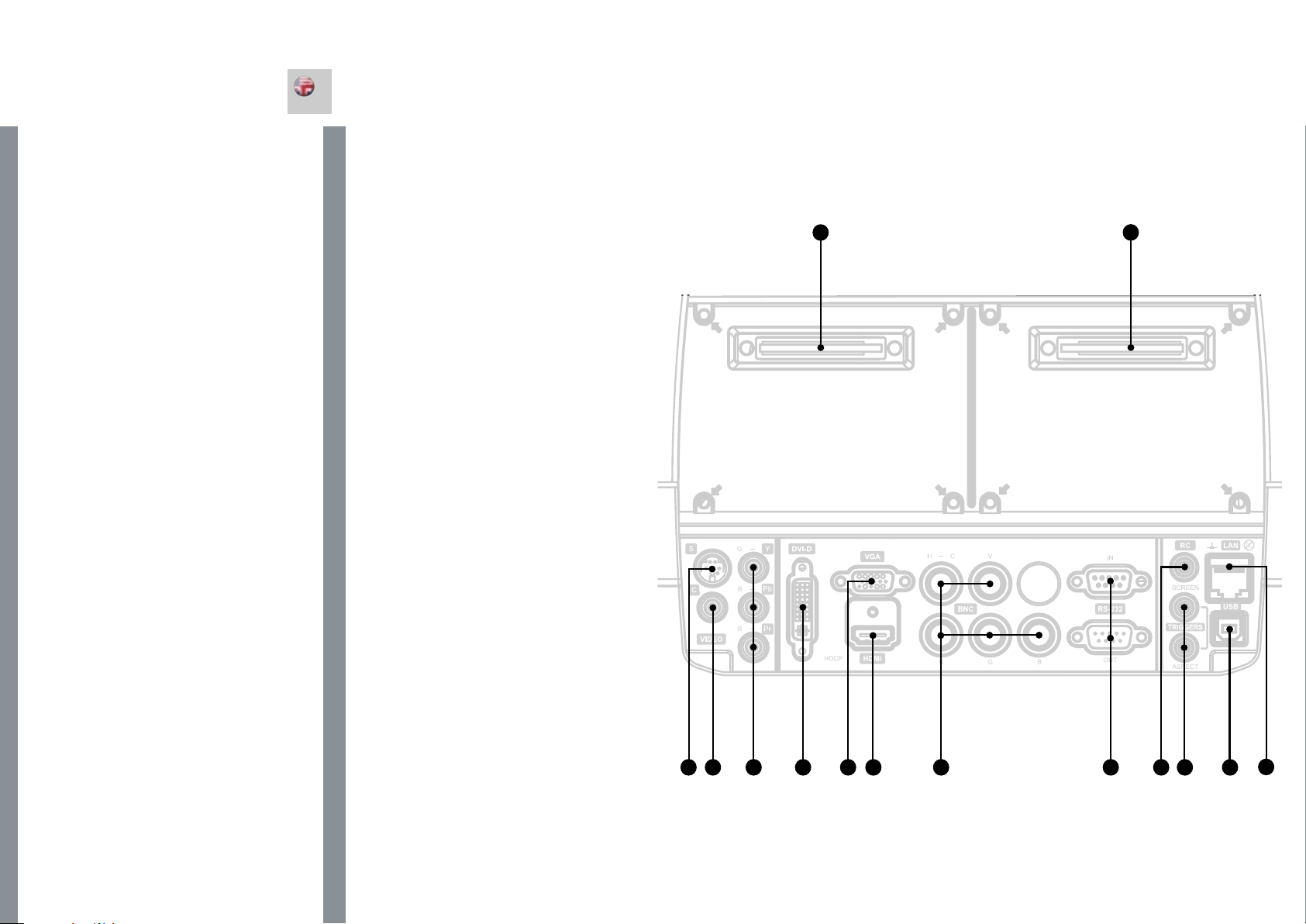
The conector panel may be illuminated by pushing the LIGHT key on
the keypad.
S-VIDEO:A Used for improved quality video.
C-VIDEO:B Used for standard video quality.
YPbPr:C Used for high quality video reproduction.
DVI-D - Digital RGB:D For a low noise computer and video image.
HDCP compatible.
VGA (analogue RGBHV):E Standard analog computer graphics
interface.
HDMI:F High quality digital RGB or YCbCr (ver. 1.3a). HDCP
compatible.
BNC (analogue RGBHV):G An alternative analog computer graphics
or video interface.
RS 232 control in-out: H Allows for wired remote control and
monitoring of many projector functions used in installation
environments. The secondary output connector allows for daisychaining, enabling both individual and global control and monitoring
of multiple projectors.
RC: I Allows connection of external IR receiver or wired remote
control.
Triggers:J 12V DC (60mA max.) for screen drop and aspect ratio
control.
USB: K Control port only.
LAN (RJ45):L Provides access to control and monitoring over a Local
Area Network.
X-Port 1, 2:M Custom interfaces used for application-specific signal
processing. Use only approved interfaces that conform to the
X-PORT specification. Not available on all models.
32
Page 18
CONNECTOR PANEL
The conector panel may be illuminated by pushing the LIGHT key on
the keypad.
A S-VIDEO: Used for improved quality video.
B C-VIDEO: Used for standard video quality.
C YPbPr: Used for high quality video reproduction.
D DVI-D - Digital RGB: For a low noise computer and video image.
HDCP compatible.
E VGA (analogue RGBHV): Standard analog computer graphics
interface.
F HDMI: High quality digital RGB or YCbCr (ver. 1.3a). HDCP
compatible.
G BNC (analogue RGBHV): An alternative analog computer graphics
or video interface.
H RS 232 control in-out: Allows for wired remote control and
monitoring of many projector functions used in installation
environments. The secondary output connector allows for daisy-
chaining, enabling both individual and global control and monitoring
of multiple projectors.
I RC: Allows connection of external IR receiver or wired remote
control.
J Triggers: 12V DC (60mA max.) for screen drop and aspect ratio
control.
K USB: Control port only.
L LAN (RJ45): Provides access to control and monitoring over a Local
Area Network.
M X-Port 1, 2: Custom interfaces used for application-specific signal
processing. Use only approved interfaces that conform to the
X-PORT specification. Not available on all models.
english
M
M
32
B C
A E G H
D
F
I
J
L
K
33
Page 19
SET UP
english
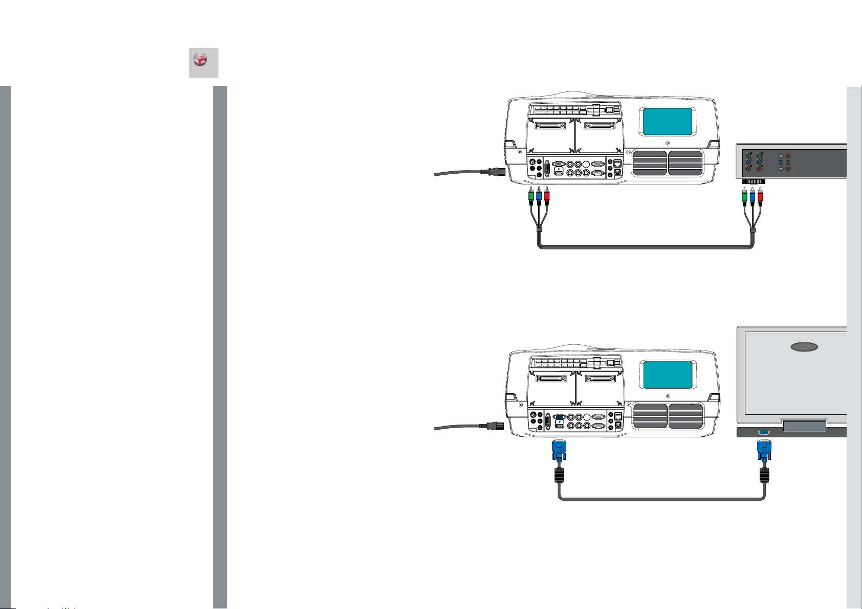
SET UP VIDEO
Before setting up, switch off all equipment.
For best quality video, connect digital video using the HDMI or DVI-D
interfaces. Both inputs are HDCP copy protection compliant.
Additionally, four analogue video sources may be connected, using the
YPbPr (component), BNC (RGB), S-VIDEO (super video) and VIDEO
(composite video) inputs.
Component and RGB video will display more detailed images.
Composite video yields images with less detail.
Connect the power cord.
SETUP COMPUTER
Before setting up, switch off all equipment.
The projector may be connected to up to four computer sources
simultaneously, using the HDMI, DVI-D, VGA, and BNC inputs.
The HDMI and DVI-D interfaces are all-digital and will yield a projected
image with very low noise.
The VGA and BNC interfaces are analog and may cause some noise
in the projected image, depending on the signal quality from the
graphics card in the computer.
Connect the RS232 interface to allow for individual or global control of
multiple units in a daisy chain configuration.
Connect the LAN connector for individual control and monitoring of
multiple projectors over LAN.
Connect the power cord.
34
Page 20
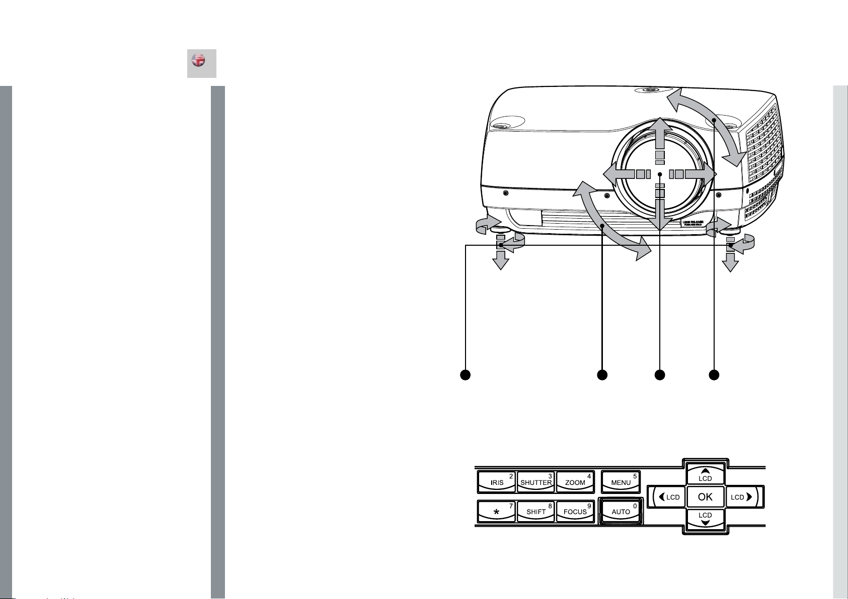
INITIAL SET UP
english
Various optical adjustments are available, depending on your choice
of lens. All lens adjustments are motorized and controlled from the
keypad, remote control or via RS232 or LAN.
Two kinds of lenses are available; fixed focal, or zoom. A fixed focal
lens has permanent focal length, or throw ratio. A zoom lens has
variable focal length or throw ratio.
In addition, fixed focal lenses may or may not be shiftable, depending
on type and model. See the specifications for the particular lens.
The throw ratio is defined as the ratio between the projection distance
to the screen and the projected image width. With a fixed lens, this
ratio is set. With a zoom lens, this ratio can be changed within certain
limits specific to the lens in use.
On the keypad, first select lens function, then use the cursor keys to
adjust. On the remote control, zoom and focus are direct keys, while
lens shift is operated by first selecting SHIFT, then use the arrow keys.
A mechanical SHUTTER is employed that totally shuts off the optical
image path. The shutter is directly available from the keypad and
the remote control. The shutter is also aactivated when no lens is
attached.
Select a lens suitable for the application. A range of lenses from ultra
wide angle to long tele zoom is available.
Adjustments to the following settings are done from the keypad
(examples); press the desired function, then adjust with arrow keys:
A Adjust the horizontal and vertical SHIFT, if applicable, in order to align
the image on screen.
B If a ZOOM lens is used, adjust the image to the right size. If a fixed
lens is used, relocate the unit to achieve the right image size.
C FOCUS the image properly.
D Adjust the IRIS to achieve the desired optical balance between
brightness and contrast. In a bright environment, brightness
is usually maximized resulting in reduced contrast. In a dark
environment, where less light is needed or desired, high contrast and
deep blacks may be appreciated.
E To level the image, adjust the feet as needed by turning the feet
accordingly.
B
AE
C
36
Page 21

LAMP OPERATION
The projector is fitted with two individual projection lamps that can be run in various modes.
In addition, lamps can be replaced as needed separately. This ensures an optimized cost of
ownership. Individual lamp timers are maintained for each lamp.
Lamp operation mode is controlled in the LAMPS sub menu.
english
PIN CODE
The projector may be locked for security by a PIN (Personal Identity Number) code. The PIN
code is 4 digits, and if the PIN code is activated, you must enter the correct code to unlock the
projector.
To activate the PIN code, see the SETTINGS > PIN CODE sub menu.
If an incorrect PIN code is entered, you may try again two times. If you fail three times in a row, a
PUK (unlock) code is needed. The PUK code is supplied with the product.
If you also fail three times with the PUK code, the projector locks up permanently, and can only
be unlocked by a special service unlock code.
To access this code, you will need to contact your dealer or a service station. The service unlock
code will be generated based on a secure, encrypted number that is produced by the projector
itself. The projector will produce a new number every time.
38
Page 22
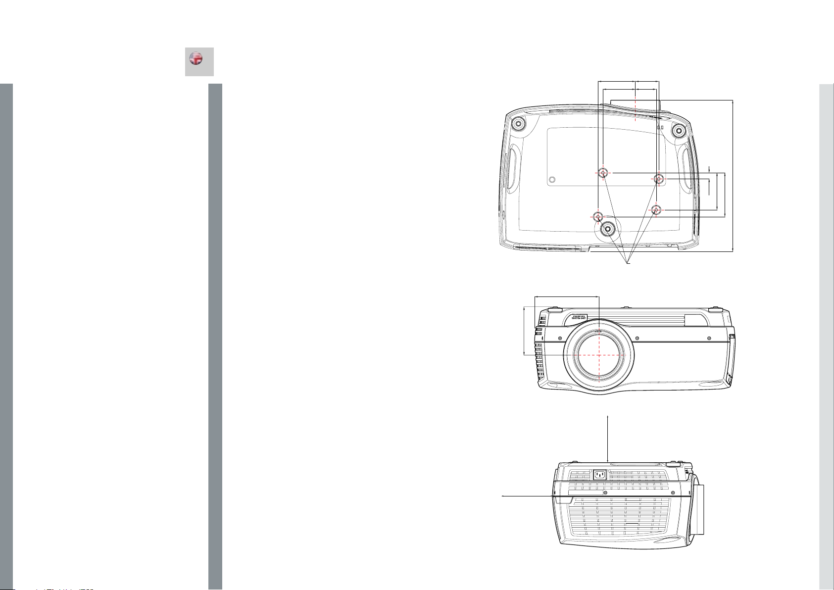
CEILING MOUNT
english
The projector can be ceiling mounted using an approved UL tested/
listed ceiling mount fixture, with a capacity of minimum 60 kg / 130
lbs.
For ceiling mount use M6 screws that penetrate maximum 15 mm /
0.6” into the projector body.
For proper ventilation the minimum distance from ceiling/ rear wall
should be: 30/ 50 cm, 12/ 20 inch.
95
59,5
82,5
163,3
123,1
53
Ceiling Mount Interface
M6 Threads
15,5
94,3
384,9
111,8
40
300mm
500mm
Page 23
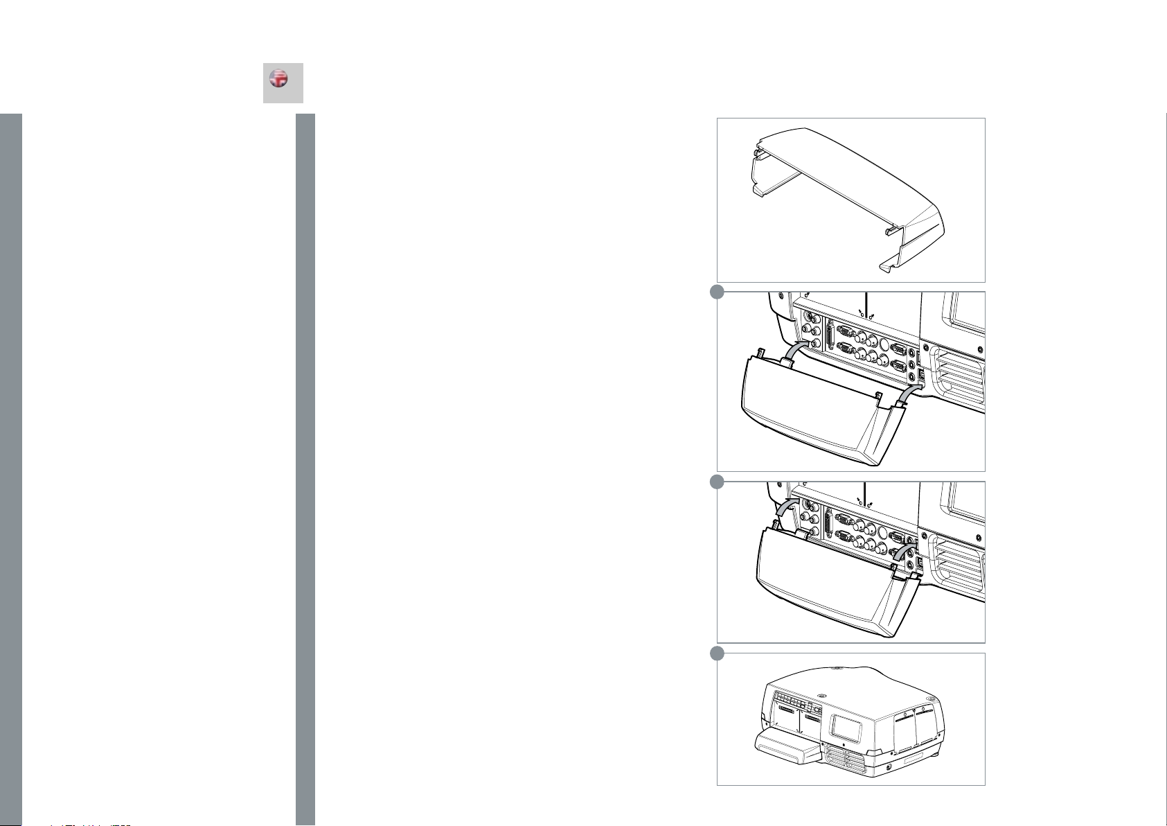
CEILING MOUNT
english
CEILING MOUNT COVER
The auxiliary cable cover can be mounted on the projector to conceal
the interface cables and power cord when the unit is ceiling mounted.
Connect all cables and fix them in place before the cable cover is
attached to the projector.
A Attach the cable cover to the projector by inserting the horisontal
hooks on the cover in the horisontal slots on the rear of the projector.
B Turn the cover untill the vertical hooks on the cover are inserted into
the vertical slots on the rear of the projector.
C The cover will snap in place, to release pull the vertical hooks on
the cover out of the slots, letting the cover hinge on the horisontal
hooks.
A
42
B
C
Page 24
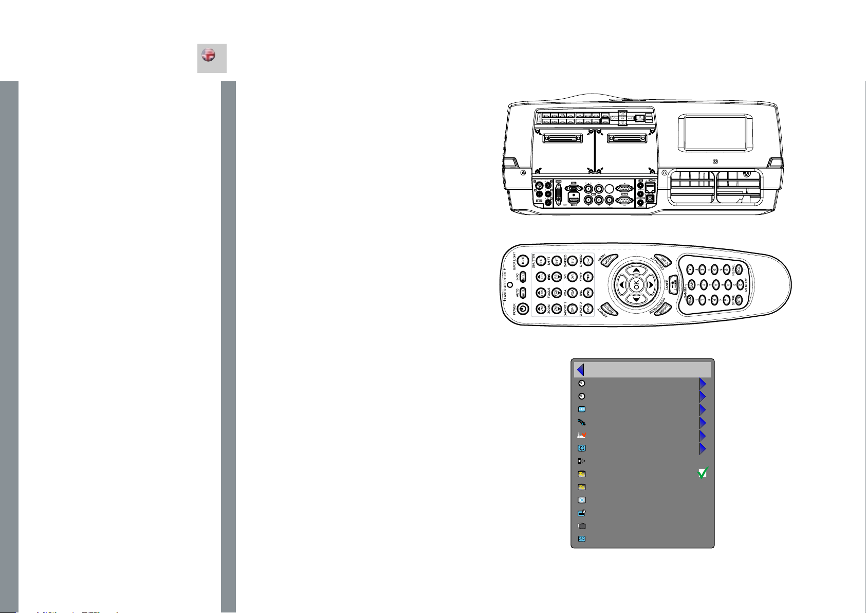
USING THE PROJECTOR
english
SWITCHING ON AND OFF
After setting up, switch on all equipment. The projector can be
controlled by the keypad, by the remote control or using the RS232
or LAN interfaces. To switch the projector on, firmly press the POWER
key on the keypad or the remote control. The STATUS indicators will
turn from yellow to blinking green when the unit is switched on, then
stabilize on permanent green either both LAMP1 and LAMP2, or either
one, depending on the lamp operation setting selected.
When using the remote control, either all or select individual units may
be addressed, see the SETTINGS sub menu - RC ID. By activating
the RC ID, individual control of units in a multiple-unit set-up is then
made possible.
The keypad with light up so that all accessible funtions are lit yellow.
Functions that are selected will turn green.
If the STATUS indicators are flashing yellow, please wait until they turn
permanent yellow. Issue the PIN code if activated.
When only one source is connected, the projector will auto-detect
that source. If more sources are connected, the projector will search
for the next active source according to the following list, provided
that SOURCE SCAN is activated in the SETTINGS sub menu (see
description of menu system):
• HDMI
• VGA
• BNC
• DVI-D
• C-video
• S-Video
• YPbPr (Component)
Select source by pressing the direct access source keys on the
keypad or the direct source selection keys on the remote control. Only
sources that are active will be displayed.
If no source is active, searching messages will appear on the screen.
If no source is active for a long time, the projector will go in standby
mode if DPMS (Display Power Management Signalling) is enabled
in the SETTINGS sub menu. The STATUS indicators will turn from
green to flashing orange, then permanent orange. The projector will
turn back on if at least one source is (re-)activated. The power-down
function can be disabled via the menu system. See DPMS in the
SETTINGS sub menu.
To switch the projector off, firmly press the POWER button on the
keypad or the remote control, and confirm with a second press. The
STATUS indicators will turn from green to flashing orange, then orange
when completely switched off. You may not switch the unit on while
the STATUS indicator is flashing orange. Please wait until the indicator
is permanent orange.
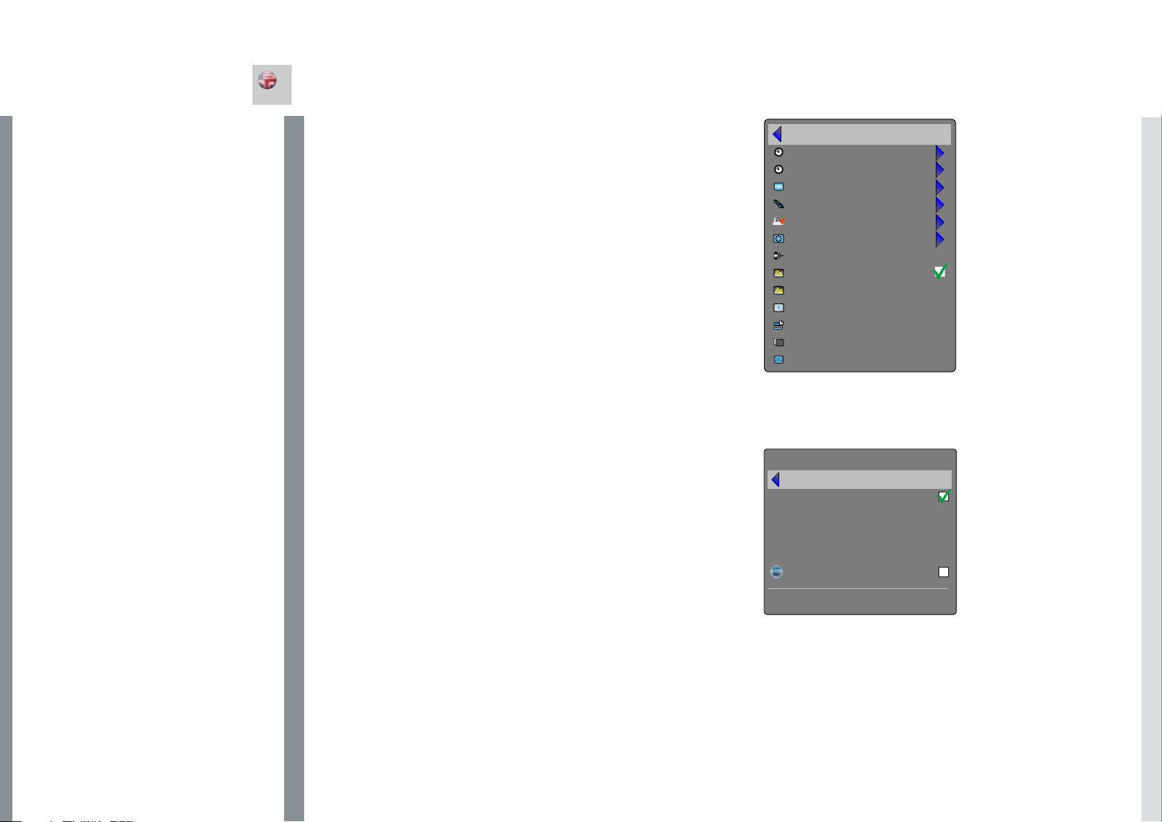
back
set date and time
timer
PIN code
network
factory reset
service
remote control ID
broadcast
DPMS
DPMS timeout
backlight timeout
menu timeout
splash
baudrate
Settings sub menu
30 minutes
30 seconds
30 seconds
black
19200
44
Page 25
USING THE PROJECTOR
english
RS 232 AND LAN CONTROL
RS 232
You may control and monitor the projector remotely through the serial
RS232 control interface.
Two RS232 protocols are employed. A simple instruction set (SIS)
ASCII protocol gives access to the most frequently used commands.
In addition, a binary protocol is available where each command is a
series of 32 bytes in one packet. The protocols allow for both SET and
GET operations. To utilize GET operations the host needs a routine
for receiving and interpreting incoming packets. SET operations
are used to force the projector into different modes, like setting
brightness and contrast, switching between sources, etc. A separate
document “RS-232 and LAN communication protocol and command
set” is available that describes the communications parameters and
operational codes in detail.
When using the RS232 interface, make sure that the baudrate is set
correctly. Baudrate can be set in the INSTALLATION menu, and can
be toggled between 4800, 9600, and 19200 bps.
LAN
The projector can be controlled and monitored through the LAN
connector as an alternative to RS232. LAN control is available
either through an embedded web page for the most frequently used
commands or using the same command set as for RS232 for full
access to all system controls.
NOTE! THE PROJECTOR IS CONFIGURED WITH A DEFAULT
IP ADDRESS. SEE THE SYSTEM INFORMATION AVAILABLE
THROUGH THE MENU SYSTEM OR REMOTE CONTROL FOR
THE ACTUAL IP-ADDRESS.
Detailed descriptions of configuration, use and command set is
described in a separate document “RS-232 and LAN communication
protocol and command set”. You may consider using the LAN
interface as a means of theft detection. When the projector is
removed, the LAN will be disconnected; this may be detected over the
local area network and could be used to trigger an alarm.
back
set date and time
timer
PIN code
network
factory reset
service
remote control ID
DPMS
DPMS timeout
backlight timeout
menu timeout
splash
baudrate
network
back
DHCP enabled
IP address
subnet mask
default gateway
TCP/UDP port
Device Discovery
MAC address
broadcast
30 minutes
30 seconds
30 seconds
black
19200
192.168.1.90
255.255.255.0
192.168.1.1
1025
00-0D-34-A0-FF-18
46
Page 26
USING THE PROJECTOR
english
TIMER
The projector features a real-time clock that enables timing control.
This means that the projector can be programmed to switch on
and off at certain pre-set times during a weekly cycle. To allow for a
flexible schedule, 10 ‘programs’ are available. With each program, you
can define the switch on or switch off time for a single day (Monday
to Sunday), all work days (Monday through Friday), or week-end
(Saturday and Sunday). One, several or all programs can be active
at the same time as desired. In this way, a flexible scheme can be
established. Observe the 24 hour time format. For more information,
see the SETTINGS > TIMER menu.
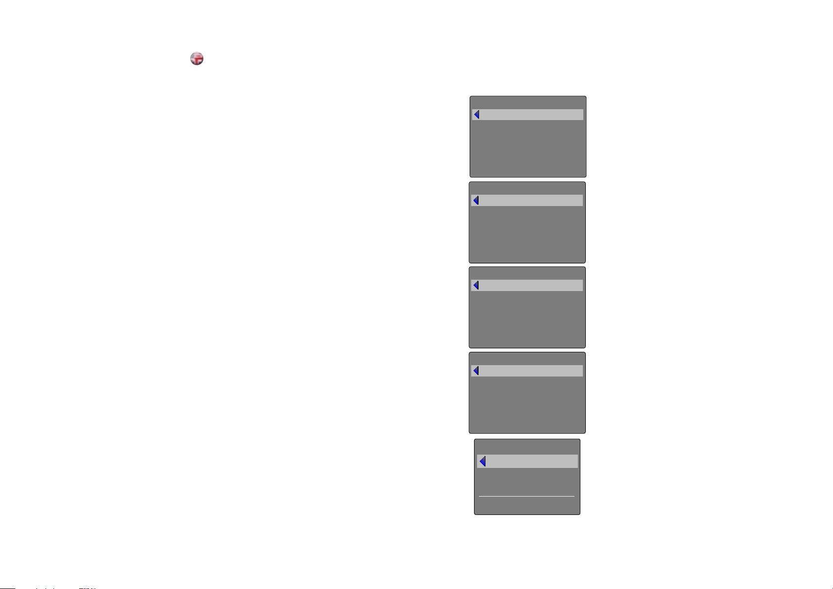
The following example illustrates a case where the projector turns
on at 08:00 in the morning (8 am) and switches off at 20:00 (8 pm)
on weekdays (Monday through Friday). Weekends (Saturdays and
Sundays), it turns on at 10:00 (10 am) and off at 18:00 (6 pm). VGA is
used as the source. For this, four programs are needed, 2 for on and
two for off.
timer
back
program number
weekday(s)
execute time
action
start-up source
status
timer
back
program number
weekday(s)
execute time
action
start-up source
status
timer
back
program number
weekday(s)
execute time
action
start-up source
status
monday - friday
08 : 00
power on
VGA
enabled
monday - friday
20 : 00
power off
VGA
enabled
saturday - sunday
10 : 00
power on
VGA
enabled
1
2
3
48
timer
back
program number
weekday(s)
execute time
action
start-up source
status
set date and time
back
date
time
day of week
saturday - sunday
4
18 : 00
power off
VGA
enabled
dd.mm.yyyy
hh:mm:ss
monday
Page 27

USING THE PROJECTOR
english
IMAGE CALIBRATION AND CORRECTION
Some applications require very precise color reproduction of the images. In addition, depending
on application, different color standards are applied. When preparing for correct color
reproduction, both the source and the projector must be considered.
The projector offers several ways to calibrate colors, as well as correction of the input signal.
The source may need correction because it is usually not calibrated from the factory, which leads
to higher or lower signal levels than nominal. In addition, R, G and B may be slightly different
(not balanced), adding a tint to the image. Correcting the input signal means adjusting the gain
(contrast) and offset (brightness) of R, G and B individually. This is in addition to the normal
brightness and contrast controls.
The projector may also need calibration regardless of the source signal, because there may
be slight differences in optical coatings, as well as the spectral distribution of individual lamps,
which can even change over time. Calibrating the projector can be done in different ways, either
by changing the color temperature, by defining the x and y color coordinates or by R, G and B
adjustment.
See the MENU system, PICTURE sub menu, for details on how to correct and calibrate.
50
Page 28
MENU
MENU SYSTEM
english
OVERVIEW
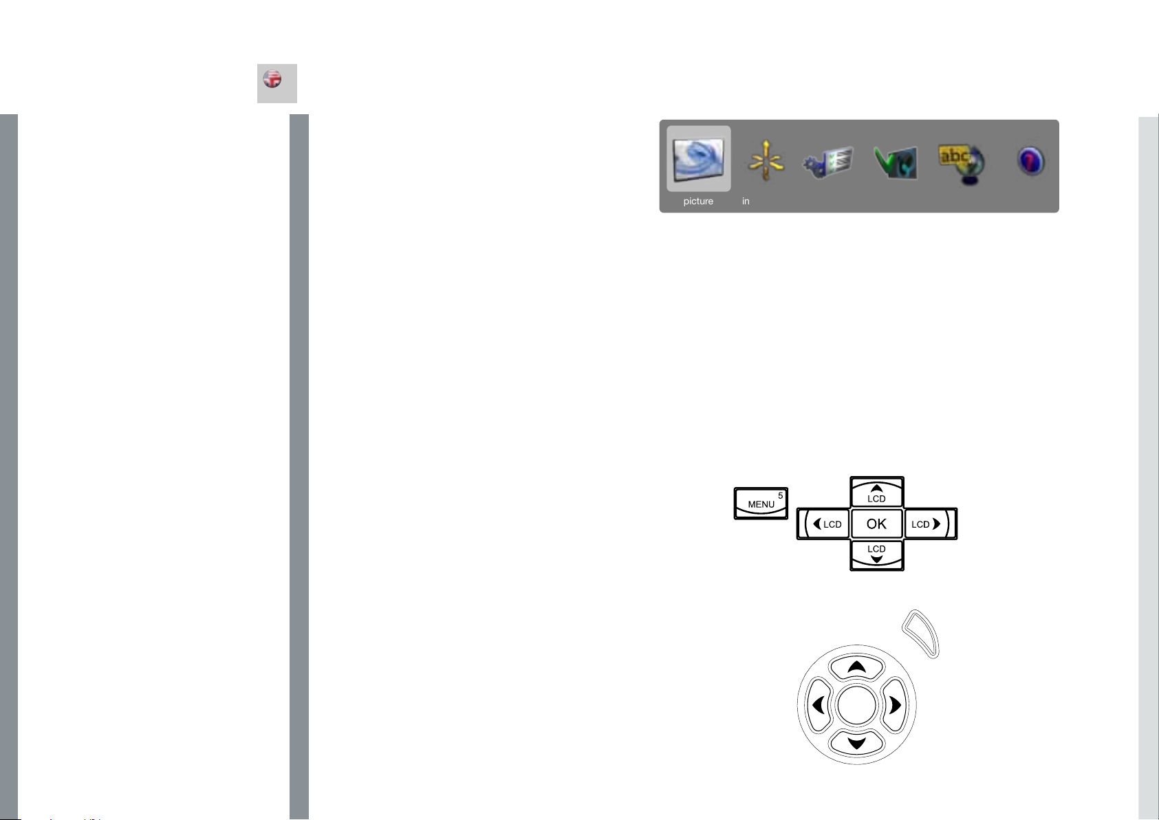
The menu system gives access to a multitude of image and system
controls. The menu system is structured through a top menu and
several sub menus. The sub menus may vary depending on the actual
source selected. Some functions are not available with some sources.
Press the MENU key and navigate using the arrow keys on the keypad
or the arrow keys on the remote control
TOP MENU
picture
Basic and advanced picture controls.
installation
System controls and information.
settings
Settings that affect how the projector behaves or interacts with third
party devices, such as networks and control systems
profiles
Pre-stored, and user defined settings.
language
Selects menu language.
status
System information.
NAVIGATING THE MENU SYSTEM
The menu system can be navigated through the on board keypad, or
via the remote control.
menu
Invokes the menu, or returns to the previous level, and exits the menu
when at top level.
OK
Selects desired function, toggles checkboxes, or enters sub menus.
Pressing OK on a directly adjustable function such as “brigthness”
minimises the menu system, and invokes a mini adjustment dialog
box. Pressing OK again returns to the full menu system
up/down arrows
Navigates up or down in menu.
left / right arrows
Moves between top level menus. Changes, or toggles adjustable
values. Enters or exits sub menus.
picture installation settings profiles language status
MENU
52
OK
Page 29
MENU SYSTEM
english
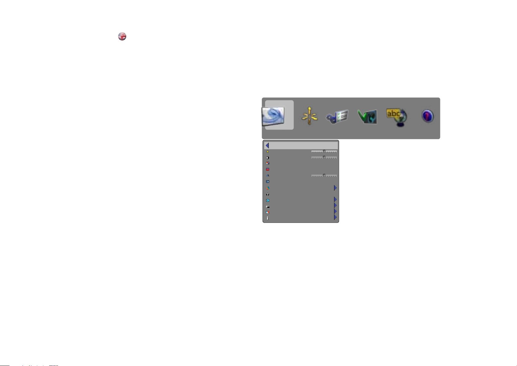
PICTURE MENU
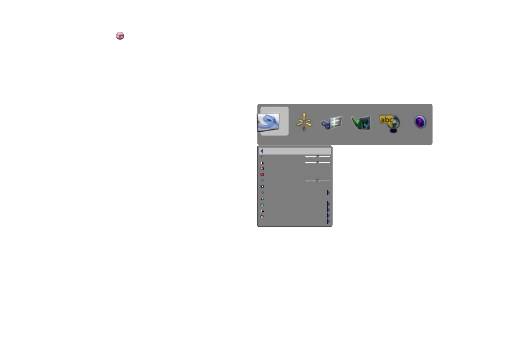
The picture menu contains basic and advanced settings and
adjustments for detailed picture enhancement control. All adjustments
are local, ie specific to each single source being displayed, and are
stored in memory as such. All picture settings are automatically stored
relative to the source, and recalled upon reconnection.
brightness
Adjusts the image brightness. A higher setting will increase the
brightness, a lower setting will decrease the brightness of the image.
contrast
Controls the contrast of the image. A higher setting will yield a ‘harder’
image with larger difference between shades, while a low setting will
produce a ‘softer’ image with less difference between shades.
color
Adjusts the color saturation. A higher setting will produce stronger
coloring, while a lower setting will yield paler colors.
hue
Adjusts the NTSC color tint. Applicable to the NTSC video standard
only. A higher setting will yield a more reddish color scheme, while a
lower setting will turn colors more greenish.
sharpness
Controls the image sharpness. A higher setting will yield a harder
image, with less filtering. In video applications, this may produce more
noise in the projected image. A lower setting will soften the image,
looking more smeared out, and reducing the overall noise.
aspect
Selects image format. An image may be displayed in various aspect
ratios. This function is used when displaying source formats that differ
from the projectors native display format. Options include “fill aspect
ratio” (default – follows the source input aspect ratio), “fill all” (streches
or compresses input aspect ratio to fill the projector resolution), “fill
16:9” (adapts the input aspect ratio to fill a 16:9 window), “letterbox to
16:9” (adapts the input to fill a center 16:9 box), and “letterbox sub title
to 16:9” (adapts the input aspect ratio to fill a 16:9 window, and
moves it up to give room for subtitles).
gamma
The source image is adapted to characteristics typical to certain
applications. This enables an optimized display of images, depending
on whether the source material is film based, video, computer etc.
picture installation settings profiles language status
back
brightness
contrast
color
hue
sharpness
aspect
color management
gamma
advanced
enhancements
picture reset
source information
50
50
fill aspect ratio
film 1
54
Page 30
MENU SYSTEM
english
RealColor
Accesses the colour management sub menu, see the Colour
management submenu for more information.
advanced
Enters the advanced settings sub menu.
enhancements
Enters the enhancement settings sub menu.
picture reset
Resets all source specific settings, such as brightness, contrast and
format settings. Picture reset does not affect global settings such as
installation specific valuses.
source information
Displays information about the source currently being displayed.
picture installation settings profiles language status
back
brightness
contrast
color
hue
sharpness
aspect
RealColor
gamma
advanced
enhancements
picture reset
source information
50
50
fill aspect ratio
film 1
56
Page 31
MENU SYSTEM
english
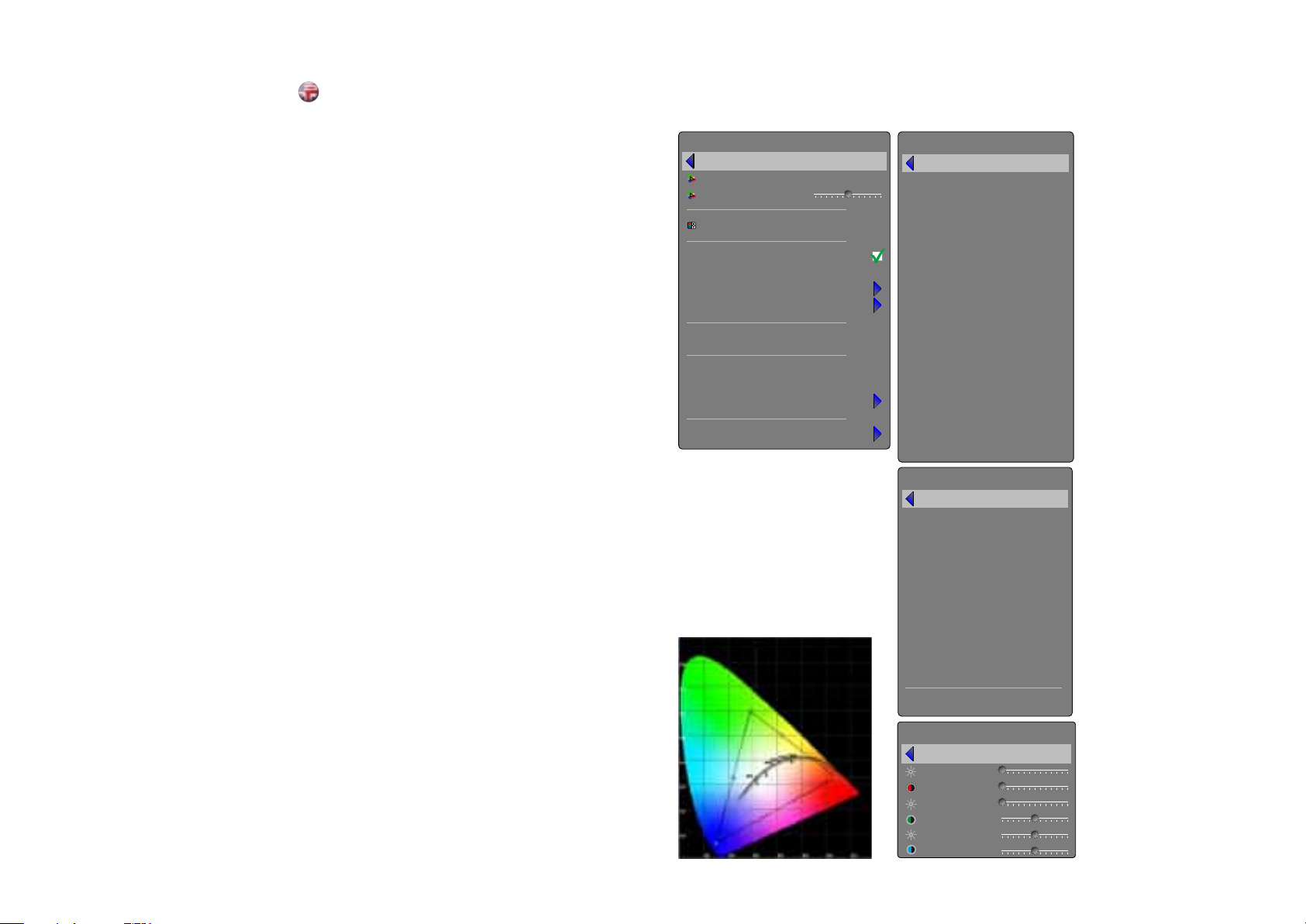
RealColor SUB MENU
The RealColor sub menu gives access easy-to-use tools to achieve
perfect colours, grey scale, and colour matching between projectors,
and is increadibly powerful. Each projector is characterized as it leaves
the factory to ensure correctly displayed images.
BrilliantColor™ preset
Sets BrilliantColor™ processing to on or off.
BrilliantColor™ boost
Adjusts the effect of BrilliantColor™ colour processing from 0 to 10.
balance gains enable
Automatically balances R, G, B, C, M, and Y intencity values so they
are correct relative to white.
desired coords mode
Allows the user to set a desired output colour gamut, used for colour
matching and accurate colour display.
desired values
When desired coords mode is set to on, the desired output colour
coordinates can be set here.
measured values
The projector’s measured colour coordinates that are used to calculate
the desired output coordinates. Custom measured values can be
entered.
temperature
Sets projected image colour temperature to a value between 3200
and 9300 degrees Kelvin when temperature is set under mode.
x-coordinate
Sets projected image white point x-coordinate when “coordinates” is
set under mode.
y-coordinate
Sets projected image white point y-coordinate when “coordinates” is
set under mode.
reset to D65
Resets the projected image white point to D65 (x=0.312, y=0.329) for
true video white colours.
display customization
Changes the R, G, and B drive output from the display.
RealColor
back
BrilliantColorTM preset
BrilliantColorTM boost
mode
balanced gains enable
desired coords mode
desired values
measured values
temperature
x-coordinate
y-coordinate
reset to D65
display customization
5
coordinates (x,y)
6500K
0.312
0.329
on
on
off
desired values
back
red x
red y
red gain
green x
green y
green gain
blue x
blue y
blue gain
cyan x
cyan y
cyan gain
magenta x
magenta y
magenta gain
yellow x
yellow y
yellow gain
measured values
back
red x
red y
red luminance
green x
green y
green luminance
blue x
blue y
blue luminance
white x
white y
0.600
0.300
0.300
0.550
0.140
0.070
0.639
0.348
0.137
0.336
0.558
0.765
0.140
0.121
0.102
0.312
0.344
58
white luminance
display customization
back
red offset
green offset
blue offset
red gain
green gain
blue gain
1.000
0
0
0
100
100
100
Page 32
MENU SYSTEM
english
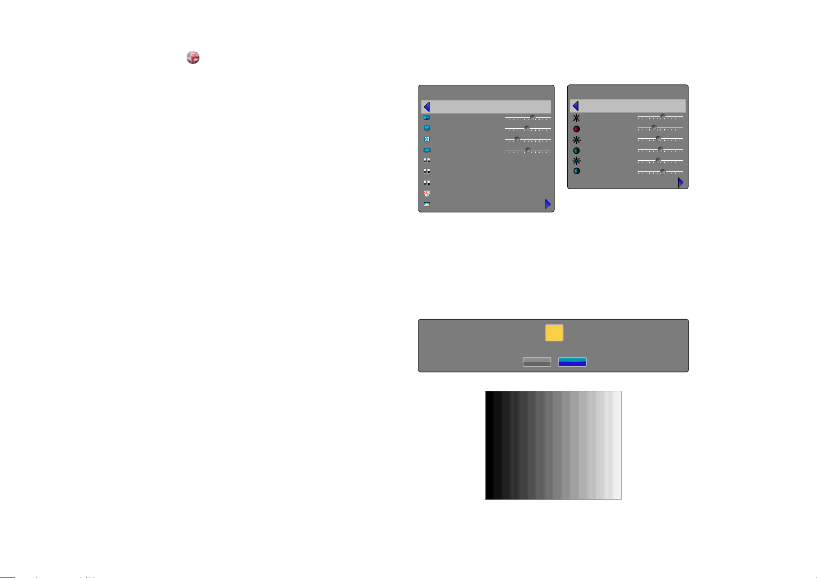
ADVANCED SUB MENU
The advanced sub menu contains less used, and more specific picture
adjustment settings.
horizontal position
Shifts the image sideways.
vertical position
Shifts the image up or down.
phase
Adjust for stable image. A jittery image may appear with certain VGA
sources. You may also press the AUTO button on the keypad or
remote control to optimize.
frequency
Adjust image width. An incorrect setting may produce vertical,
unstable bands in the image, and parts of the image may not be
displayed on screen. Push the AUTO button to find a correct setting,
or manually adjust the frequency until the vertical bands disappear.
Frequency adjusts the pixel clock sampling frequency.
IRE setup
Sets black level for NTSC video input sources.
digital level
Sets the dynamic range for the digital inputs to video or range; 16 –
234 or 0 – 255.
digital level and colour space
When set to automatic, the projector automatically detects both the
colour space and the level of the digital input signal over HDMI or DVI.
Manual lets the user override the detection.
digital color space
Sets digital colour space to RGB or YUV.
source correction
Only available with an analogue RGB input signal. Optimises input
signal for processing. Use this to correct for source signal level
inaccuracies. The AD calibration process can only be performed with
a specific input test image for accurate results. Use with an incorrectly
displayed image may result in reduced performance. For more
information, please contact your dealer, or visit our web site.
advanced
back
horizontal position
vertical position
phase
frequency
IRE setup
digital level and color space
digital level
digital color space
source correction
267
31
8
1312
7.5 IRE
auto
source correction
back
red offset
green offset
blue offset
red gain
green gain
blue gain
AD calibration
0
0
0
100
100
100
!
using this function without the correct input signal may result in reduced image quality
yes no
60
Page 33

MENU SYSTEM
english
ENHANCEMENTS SUB MENU
The enhancements sub menu contains a range of picture
enhancement settings for analogue video inputs.
DLTI (Digital Luminance Transient Improvement) level
Use this function to increase visible image sharpness.
DCTI (Digital Chroma Transient Improvement) level
Use this function to increase visible colour sharpness in video images.
3D comb filter
This filter reduces dot crawl in composite video signals.
2D peaking
A collection of built-in filters provided to enhance detail display in
edges and blocks.
adaptive noise reduction
This filter adapts to the source material, and reduces noise in motion
video.
CEH (Colour Enhancement) red, blue, green, yellow,
fleshtone
The Colour Enhancement filters enhance individual colours by
analyzing the image, and allowing gain (contrast) to the colour
selected. Fleshtone adjustment enhances the gain setting for a range
of colours that are typical flesh tones.
horizontal deblocking
A 2D filter that analyzes each frame for jaggies and blocking, and
reduces so called MPEG blocking artefacts typical with DVD and other
compressed video formats.
dynamic contrast enhancement
Dynamically adjusts and adapts image contrast.
dynamic contrast level
Dynamically adjusts and adapts image contrast.
enhancements
back
DLTI level
DCTI level
3D comb filter
2D peaking
adaptive noise reduction
CEH red
CEH blue
CEH green
CEH yellow
CEH fleshtone
dynamic contrast enhancement
dynamic contrast level
horizontal deblocking
6
6
0
1
1
1
1
1
on
18
off
62
Page 34
MENU SYSTEM
english
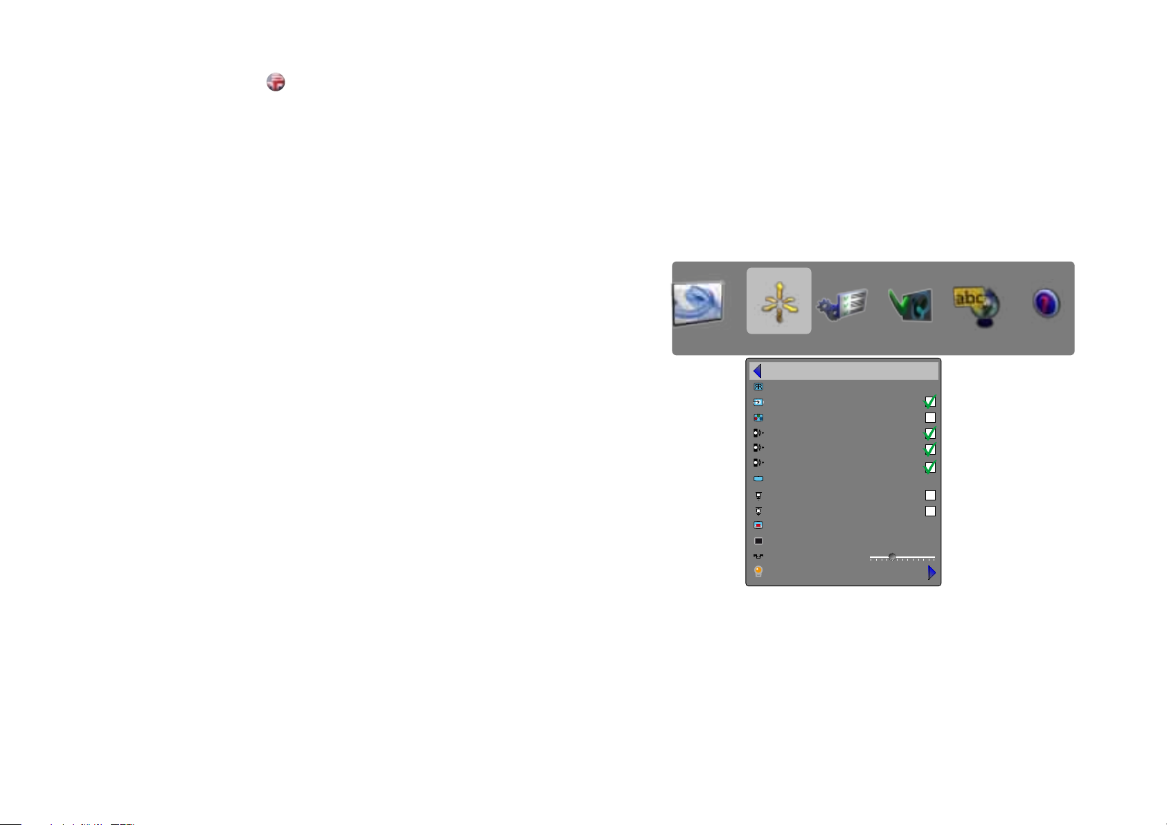
INSTALLATION SUB MENU
The installation sub menu provides easy access to global system
settings, including ceiling mount and rear projection settings, analogue
source sync termination settings, and keystone. These settings will
affect all sources connected, and are system specific, rather than
source specific.
image orientatation
Set the image orientation to reflect the installation setting.Select
between “desktop front”, “desktop rear”, “ceiling front” and “ceiling
rear” modes. The image will be flipped and reversed accordingly.
source scan
When enabled, the projector automatically searches for available
sources on all input terminals, and displays the image from the first
one available with a valid input signal. Source scan is on by dafault.
RGB video
The component video input can be configuted to receive RGB
and composite sync (using the composite video input as a fourth
connector).
IR front, rear right/left
Enables or disables individual IR receivers. Disable if the projector is
being used with a control system, if the projector experiences strange
behaviour (due to stray IR light in some environments), or the remote
control is not needed. IR enable is on by default.
wide setup
Wide setup gives manual control to correctly displaying sources that
are wide aspect ratio of standard resolutions, such as 1680x1050
(SXGA+), 1280x768 (WXGA), and similar.
sync termination VGA, BNC
Changes the input impedance to match source signal impedance. Use
if signal is fuzzy or unstable.
OSD enble
Enables or disables the OSD (On Screen Display) dialogues. Possible
settings include “on”, “off”, or “only warnings”. The latter will display
system warnings, such as overheating, lamp life expiry, other other
critical information. “off” disables all warnings and messages. OSD
enable is set to “on” by default.
test image
Displays a test image frame that is easy to use when setting up and
determining screen size, and position. Options include 4:3, 16:9,
1.85:1, 2.35:1, and a combination of all of the above.
Sync level
Manually changes the level of sync that is needed for the projector to
accept it.
Warning! If set too low, the image will disappear!
lamp
Enters the lamp management sub menu.
picture installation settings profiles language status
back
image orientation
source scan
RGB video
IR front
IR rear right
IR rear left
wide setup
sync termination VGA
sync termination DVI-A
OSD enable
test image
sync level
lamp
desktop front
on
only warnings
off
8
64
Page 35
MENU SYSTEM
english
LAMP SUB MENU
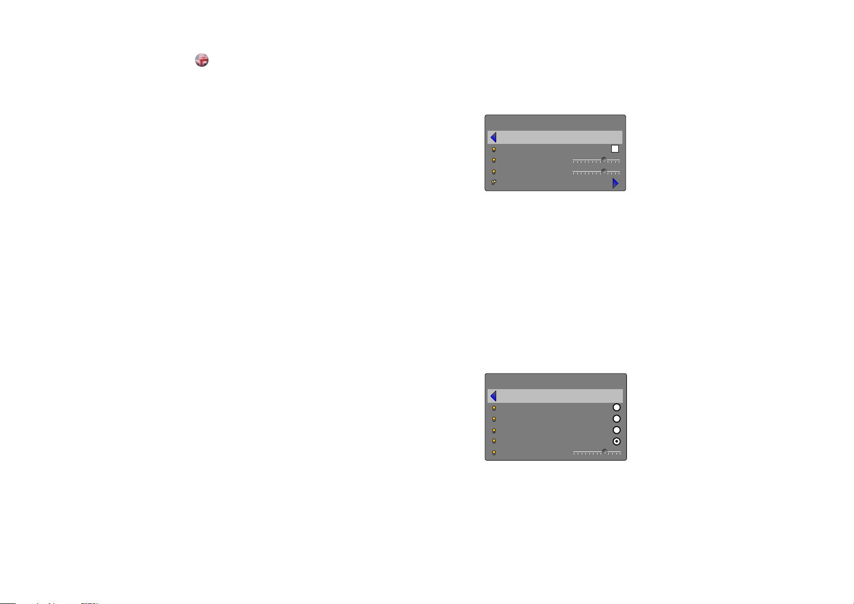
eco mode
Switch eco mode (low power and long life) on or off. When on, lamp
power may not be adjusted. When off, lamp power may be adjusted.
lamp 1, 2 power
Adjust lamp power when not in eco mode. Individual control of each
lamp.
lamp mode
Enters the lamp mode sub menu.
LAMP MODE SUB MENU
single 1, 2
Selects which lamp to run in single lamp mode.
dual
Runs both lamps simultaneously.
auto switch
Enables automatic switching between the two lamps.
auto switch delay
Sets the delay and timing when switching automatically. Delay can be
adjusted in 1 hour steps from 1 - 24 hours.
lamp
back
eco mode
lamp 1 power
lamp 1 power
reset lamp timer
lamp mode
back
single 1
single 2
dual
auto switch
auto switch delay
18 hrs
66
Page 36
MENU SYSTEM
english
SETTINGS SUB MENU
The settings sub menu contains settings that are system specific, and
source independent, such as networking, and third party equipment
interaction, display power management, PIN code and security
settings, amongst other things.
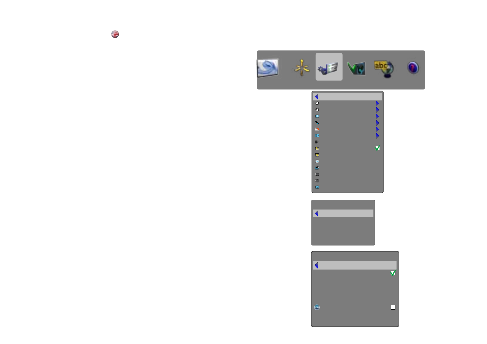
set date and time
Set system date and time for the projector to utilise timer and
programming options.
Date and time are easiest set with the remote control. Select either
date or time, press “OK” on the remote control, and the first digit will
be highlighted. Change value with the up / down arrow keys, and
move between values with the left / right arrow keys. Press OK when
done. Day of week is automatically set when a date is set.
timer
The projector can be programmed to power up or down at any time
desired, using the timer option. See example on pages 40 - 41.
Configure “program number” (1-10), “weekday(s)”, “execute time”, and
“start up source” (the input the projector defaults to when starting up)
, and enable or disable the programme.
Select the value to be edited, and change the value with the left / rigth
arrow keys.
For “execute time”, press “OK”, change value with the up / down
arrow keys, move between values with the left / right arrow keys.
PIN code
The projector can be secured and locked with a 4-digit PIN (Personal
Identification Number) code, similarly to mobile phones and other
electronic equipment. To enable PIN code protection, a valid, four-digit
code must be entered. Press “OK” to select the code, enter new PIN
code via the numeric pad on the keypad or remote control. Please
note that entered numbers are masked. To disable PIN code, or
change it, follow the same procedure as above.
When PIN code is enabled, the user is prompted to enter the code
when powering up the projector. The user has three attempts. See PIN
code security on page 30 - 31 for more information.
network
The projector features a built-in network connector for asset
management and control over IP. The network menu allows enabling
DHCP in order to automatically be assigned an IP when connected, or
setting a static IP address, subnet mask, and default gateway.
Highlight the setting to be changed, press “OK”, and change the
values with the up / down arrow keys. Move beteween values with the
left / right arrow keys.
factory reset
Factory reset erases all memorised source and system settings, and
sets all back to default values.
service
Service enters the service menu. This is available to authorised service
personnel only. Entering the service menu without proper knowledge
may permanentely damage the projector.
picture installation settings profiles language status
back
set date and time
timer
PIN code
network
factory reset
service
remote control ID
DPMS
DPMS timeout
backlight timeout
menu timeout
background
splash
baudrate
set date and time
broadcast
30 minutes
30 seconds
30 seconds
black
logo
19200
back
date
time
day of week
dd.mm.yyyy
hh:mm:ss
monday
network
back
DHCP enabled
IP address
subnet mask
default gateway
TCP/UDP port
192.168.1.90
255.255.255.0
192.168.1.1
1025
Device Discovery
68
MAC address
00-0D-34-A0-FF-18
Page 37
MENU SYSTEM
english
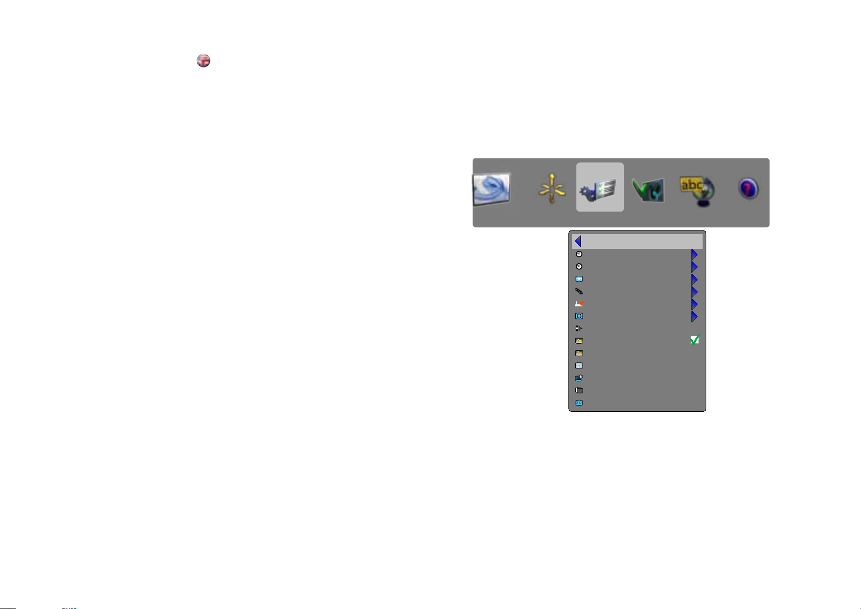
remote control ID
The projector can be set up to have a unique ID, so that it only
responds to remote controls transmitting the same ID. Up to 99 units
can be handled without interfering with eachother, using the same
remote. By default, the projector is set to respond to any one remote
control, thus is set to “broadcast”. To change, and set a unique ID,
select, and change the value with the left / right arrow keys.
To set the remote control to broadcast to a specific ID, press the
asterisk key (“*”), and enter a number that corresponds with the
projector you wish to control using the numeric keypad. When
pressing the asterisk key towards a projector, it will respond with its
unique ID, and prompt the user to enter a matching one.
DPMS
Enable or disable the DPMS (Display Power Management Signalling).
When enabled, the projector will automatically switch to standby mode
after a specified time if there is no valid source present at its inputs.
When a valid source is reconnected, the projector will start up again.
DPMS timeout
DPMS can be set from 1 – 180 minutes. Default is 30 minutes.
backlight timeout
Set the amount of time before the backlight for the on-board keypad
fades out after use. Default is 30 seconds.
menu timeout
Set the amount of time before the menu automatically goes away if
not used. Default is 30 seconds.
splash
Select the splash screen to be displayed if no valid source is
connected. Options include black, grey, and white.
baudrate
Set the baudrate at which the projector communicates over
RS232. Options include 4800, 9600, and 19200 bps. See separate
documentation for details on RS232 and LAN communications.
picture installation settings profiles language status
back
set date and time
timer
PIN code
network
factory reset
service
remote control ID
DPMS
DPMS timeout
backlight timeout
menu timeout
splash
baudrate
broadcast
30 minutes
30 seconds
30 seconds
black
19200
70
Page 38
MENU SYSTEM
english
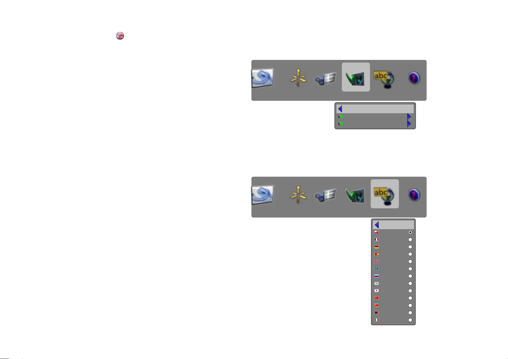
PROFILES SUB MENU
The profiles sub menu contains predefined and user saved projector
setup profiles, so that a specific setting or desired projection mode
quickly can be reinstated.
store settings
Displays information about the source and projector status.
recall settings
Turn the On Screen Display on (display) or off (hide) during source
scan.
LANGUAGES SUB MENU
Selects menu language.
picture installation settings profiles language status
back
store settings
recall settings
72
picture installation settings profiles language status
back
english
français
Deutsch
español
norsk
svensk
Русский
한국어
日本語
?体中文
繁體中文
português
italiano
Page 39
MENU SYSTEM
english
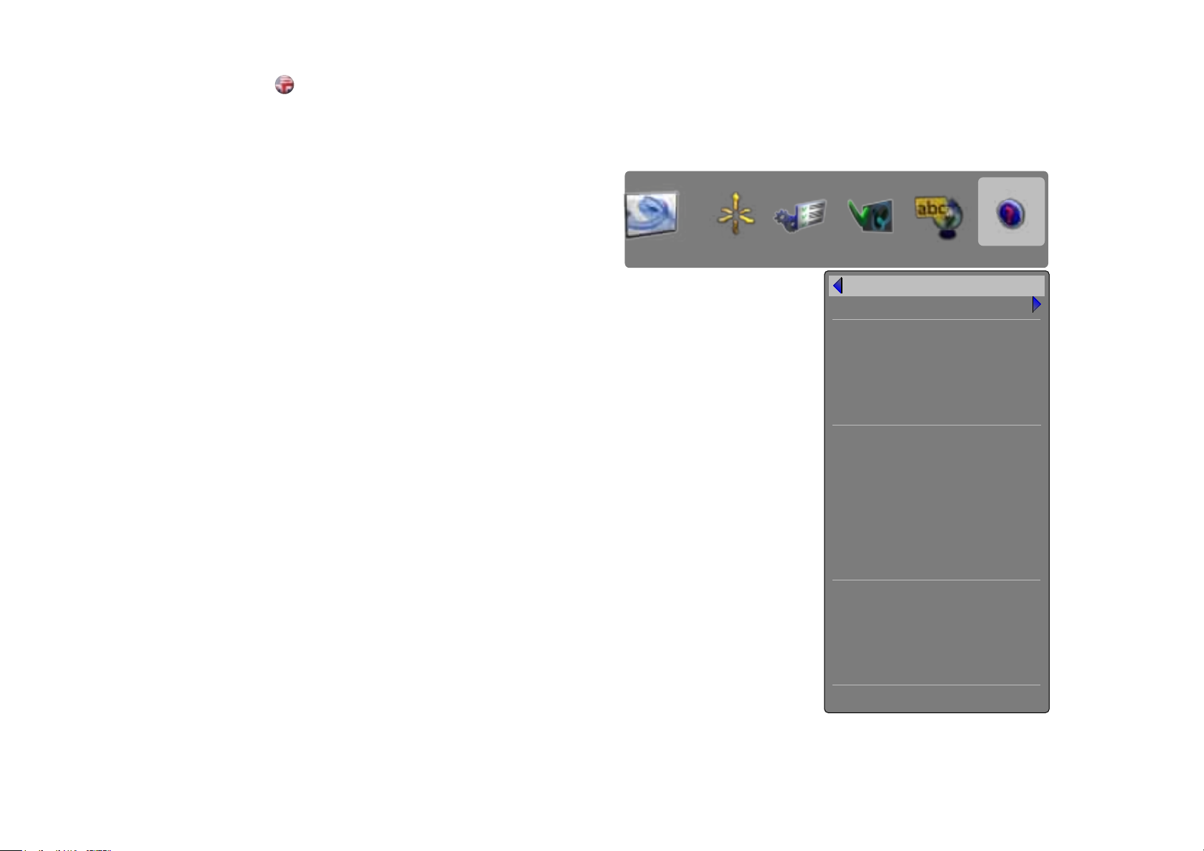
STATUS SUB MENU
The status sub menu can be invoked through the menu system, or
directly from the “INFO” key on the remote control. It gives direct, and
easy to understand information on system and connected source
status.
picture installation settings profiles language status
back
source information
part number
serial number
manufactured (y)
manufactured (w)
software version
lamp 1 remaining
lamp 1 time
lamp 2 remaining
lamp 2 time
total operating
lamp 1 power
lamp 2 power
lamp mode
MAC address
IP address
subnet mask
default gateway
TCP/UDP port
ØØØ-ØØØØ-ØØ
ШШШШШШШШШ
YYYY
WW
ØØØ-ØØØØ-ØØ
ØØØØ hrs
ØØ hrs
ØØØØ hrs
ØØ hrs
ØØ hrs
ØØ
ØØ
dual
00-0D-8A-43-2A-0B
192.168.1.90
255.255.255.0
198.162.1.1
1025
lens mounted standard (1.60 - 2.32 : 1)
74
Page 40

TROUBLE SHOOTING
english
NO IMAGE
No connection:
Check if all connections are properly made.
Source off:
Check if the equipment is powered on.
Lamp dead:
The lamp may need replacement.
Source hibernated:
Engage the source to display and activate image.
Notebook external screen:
Different notebook PC’s use different combinations of keystrokes to enable the external graphics
port.
Source scan off:
Check SOURCE SCAN in the INSTALLATION sub menu. If setting is OFF, the projector will not
search for the next active source, but will remain with the current source selected.
Lens cap:
Check that the lens cap is off!
DARK IMAGE
Old, worn lamp:
The lamp may need replacement. Check the lam life time in the STATUS sub menu.
Low brightness or contrast settings:
Use the remote control or the menu system, PICTURE sub menu for CONTRAST and
BRIGHTNESS adjustment.
FLICKERING IMAGE
Bad lamp:
Replace the lamp. Check the LAMP TIME in the STATUS sub menu.
UNSHARP IMAGE
Lens not focused:
Focus the lens properly. Keystone correction may have been activated inadvertently: Parts of the
image is compressed that affects the display of fine-line graphics, text and other images of high
resolution.
Source resolution is different from projectors native resolution:
The projector will automatically scale and resize the input format to its native resolution. Use
a different scaling factor in the PICTURE sub menu, ASPECT RATIO. You may also adjust the
SHARPNESS.
76
Page 41

MAINTENANCE
The projector may from time to time need cleaning. Never open the unit, as this will void any
warranties. Refer service and repair to qualified personnel only.
The projector is using lamps that have a limited life time. Please refer to the LAMP CHANGE
section below for further details.
Only the exterior of the unit may be cleaned. Use a damp cloth. Make sure no liquids enter the
inside of the projector Vacuum clean all the air vents (A) regularly to maintain sufficient air flow.
The projection lens (B) is sensitive to scratches. Use lens cleaning tissue, available at all
photographic stores when cleaning the projection lens. Use lens cap when not in use.
english
HEAVY DUTY AND CONTINOUS USE
The projector contains moving parts (such as cooling fans) that have limited life-expectancies.
When the projector has been used for 8 000 hours, and when the unit is used in mission-critical
applications, it is recommended that the projector is given preventive maintenance by a qualified
service person. This will help ensure long term stable operation.
This product contains no user serviceable parts. If the product fails to function as expected,
please first check that all connections are properly made, and that the power cord is properly
SERVICE INFORMATION
connected. Please check that the projector as well as the video and computer sources are all
switched on. Cables and cords may break over time. Try to change cables and cords, in case
there is a bad or intermittent connection. Check if the circuit breaker or fuse of your mains
is intact. In the event of product failure, please contact your reseller. You should prepare a
description of the symptoms of failure you experience. Please also state product number and
serial number as printed on the label on the bottom of the projector.
SERVICE PERSONNEL INFORMATION
WARNING
Use UV radiation eye and skin protection during servicing.
78
Page 42
LAMP CHANGE
english
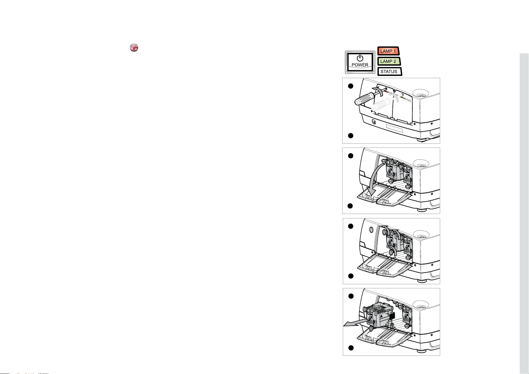
The LAMP indicators on the keypad will turn red when lamp life
expires.
Change the lamp when lifetime expires. Always replace lamp with the
same type and rating.
The lamp includes an electronic lamp timer that is tracking the life time
of the lamp.
Allow lamp to cool down before changing. One lamp may be changed
while the other lamp is operating (hot-swap).
A Release the screw (LAMP 1) or (LAMP 2) depending on which lamp
that needs to be replaced.
B Open the lamp lid(s).
C Turn the three locking screws a quarter turn anti-clockwise.
D Pull the lamp out.
Replace with a new lamp in reverse order.
E Insert a new lamp. Observe the guide pins.
F Turn the tree locking screws a quarter turn clockwise.
G Close the lamp lid.
H Turn the locking screw clockwise.
WARNING
Be careful not to touch the protective glass when replacing the
lamp house, this may cause the protective glass to overheat and
break while in use.
WARNING
Be extremely careful when removing the lamp module. In the
unlikely event that the bulb ruptures, small glass fragments may
be generated. The lamp module is designed to contain these
fragments, but use caution when removing the lamp module.
A
I
B
H
C
F
D
E
81
Page 43
TECHNICAL DATA
english
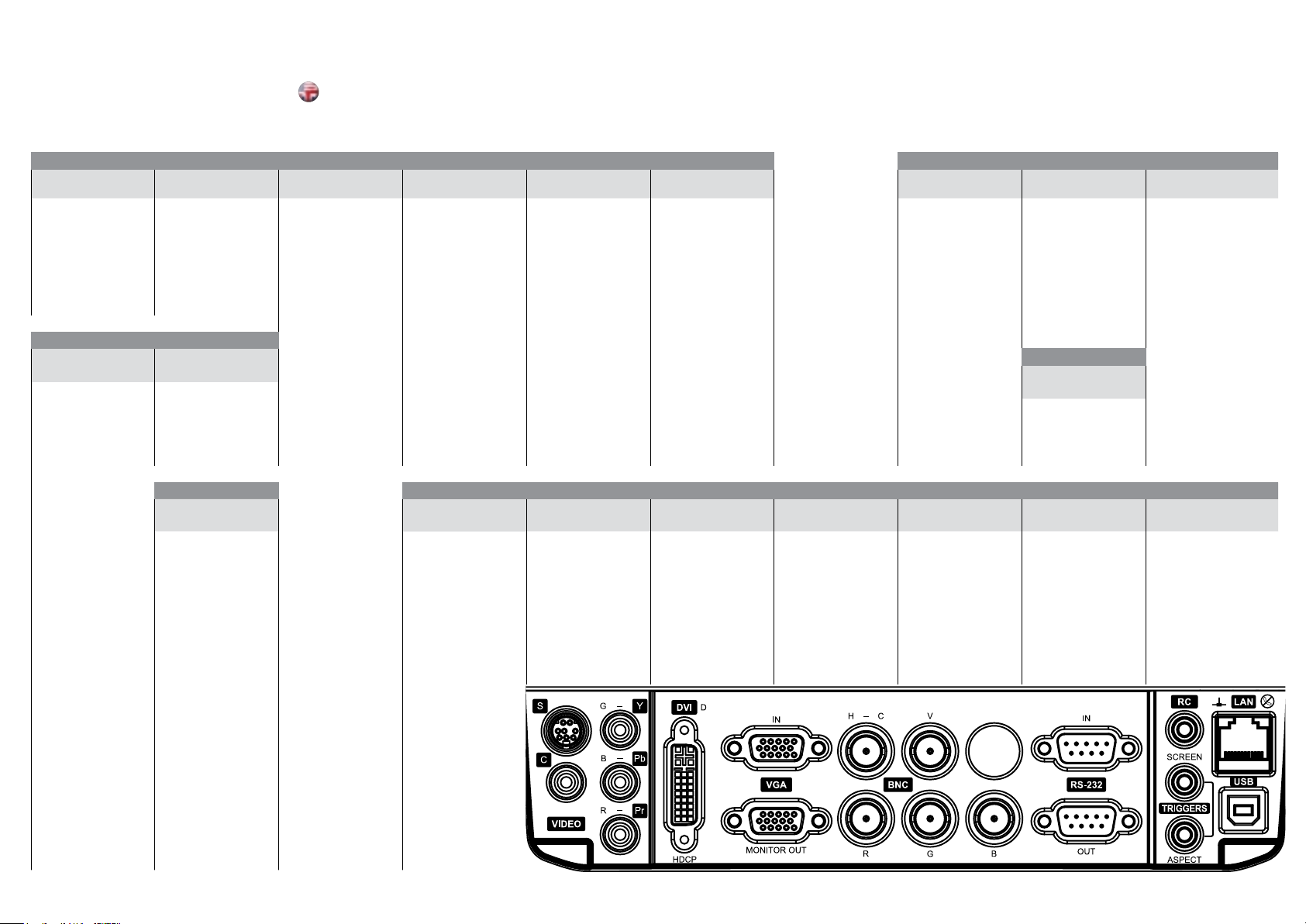
CONNECTORS STECKER CONNECTEURS CONECTADORES
S-Video G/Y Computer DVI Computer VGA 1 BNC H - C BNC V RS-232 in RC in LAN
4 PIN MINI DIN FEMALE
1 GND STEM GREEN: G/Y 1 TMDS Data 2- 1 Analog R in STEM: Horizontal/ STEM: Vertical 1 NC TIP: 5V DC 1TX+
2 GND SHIELD: GND 2 TMDS Data 2+ 2 Analog G in Composite sync. sync. 2 RXD RING: SIGNAL 2TX3 Luma 3 TMDS Data 2/4 Shield 3 Analog B in SHIELD: GND SHIELD: GND 3 TXD STEM: GND 3RX+
4 Chroma 4 Not used 4 AGND 4 NC 4GND
C-Video B/Pb
PHONO/RCA FEMALE PHONO/RCA FEMALE
STEM YELLOW: STEM BLUE: B/Pb 12 Not used 12 DDC/SDA
Composite SHIELD: GND 13 Not used 13 H Sync in TIP: 12V DC
SHIELD: GND 14 +5V Power 14 V Sync in 60mA max
82
82
PHONO/RCA
FEMALE
R/Pr HDMI BNC R BNC G BNC B RS-232 out Aspect USB
PHONO/RCA FEMALE HDMI BNC MALE BNC MALE BNC MALE 9 PIN DSUB MALE 3.5mm mini jack DIGITAL USB
STEM RED: R/Pr 1 TMDS Data 2 + STEM: RED STEM: GREEN STEM: BLUE 1 NC TIP: 12V DC 1 VCC
SHIELD: GND 2 TMDS Data 2 Shield SHIELD: GND SHIELD: GND SHIELD: GND 2 TXD 80mA max 2 -Data
DVI-D
5 Not used 5 AGND 5 GND 5GND
6 DDC Clock 6 Analog R GND in 6 NC 6RX7 DDC Data 7 Analog G GND in 7 NC 7GND
8 NC 8 Analog B GND in 8 NC 8GND
9 TMDS Data 1- 9 Reserved
10 TMDS Data 1+ 10 Sync GND in
11 TMDS Data 1/3 Shield 11 AGND
15 HIGH DENSITY
DSUB FEMALE
15 DDC/SCL STEM: GND
3 TMDS Data 2 - 3 RXD STEM: GND 3 +Data
4 TMDS Data 1 + 4 NC 4 GND
5 TMDS Data 1 Shield 5 GND
6 TMDS Data 1 - 6 NC
7 TMDS Data 0 + 7 NC
8 TMDS Data 0 Shield 8 NC
9 TMDS Data 0 -
10 TMDS Clock +
11 TMDS Clock Shield
12 TMDS Clock 13 CEC
14 Not Used
15 DDC Clock
16 DDC Data
17 Ground
18 +5V Power
19 Hot Plug Connect
20 Shell
BNC MALE BNC MALE 9 PIN DSUB FEMALE
3,5mm stereo
mini jack
Screen
3.5mm mini jack
RJ 45
Page 44
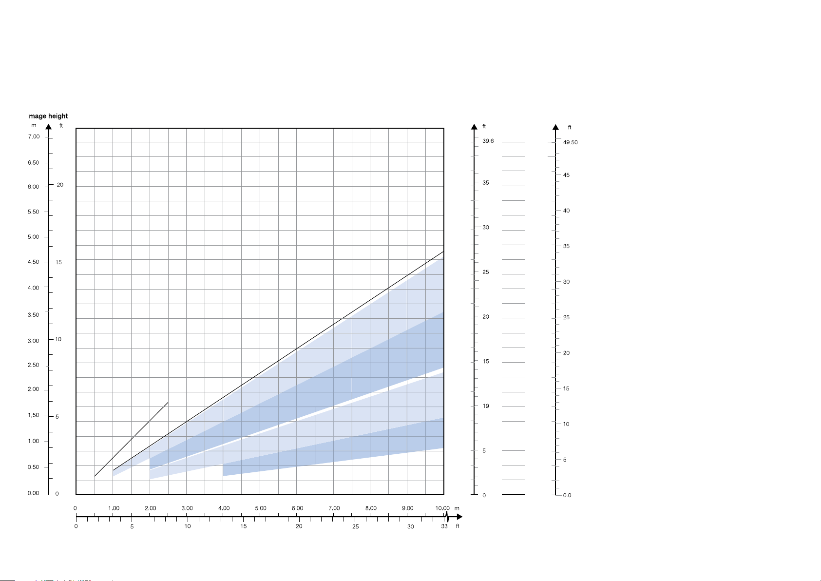
IMAGE SIZES BILDGRÖßE TAILLE D’IMAGE TAMAÑO DE PANTALLA
1920x1080
Image width
m
12.00
11.00
10.00
9.00
8.00
7.00
6.00
5.00
Wide Angle 1.16 : 1 (1.0 - 15m)
Wide Angle Zoom 1.24 - 1.60 : 1 (1.0 - 15m)
Standard Zoom 1.60 - 2.32 : 1 (2.0 - 15m)
Ultra Wide Angle 0.79 : 1 (0.5 - 2.5m)
Tele Zoom 2.37 - 3.79 : 1 (2.0 - 30m)
Long Tele Zoom 3.80 - 6.50 : 1 (4.0 – 40 m)
4.00
3.00
2.00
1.00
0
Screen diagonal
m
15.00
13.75
12.50
11.25
10.00
8,75
7.50
6.25
5.00
3.75
2.50
1.25
0
84
Projection distance
Page 45
DIMENSIONI DELLO SCHERMO SKJERMSTØRRELSER
1280x720
Wide Angle 1.37 : 1 (1.0 - 15m)
Wide Angle Zoom 1.46 - 1.9 : 1 (1.0 - 15m)
Standard Zoom 1.9 - 2.75 : 1 (2.0 - 15m)
Ultra Wide Angle 0.93 : 1 (0.5 - 2.5m)
Tele Zoom 2.8 - 4.49 : 1 (2.0 - 30m)
Zoom Tele Zoom 4.5 - 7.8 : 1 (4.0 - 40m)
Image width
m
12.00
11.00
10.00
9.00
8.00
7.00
6.00
5.00
4.00
3.00
2.00
1.00
0
Screen diagonal
m
15.00
13.75
12.50
11.25
10.00
8,75
7.50
6.25
5.00
3.75
2.50
1.25
0
Projection distance
85
Page 46
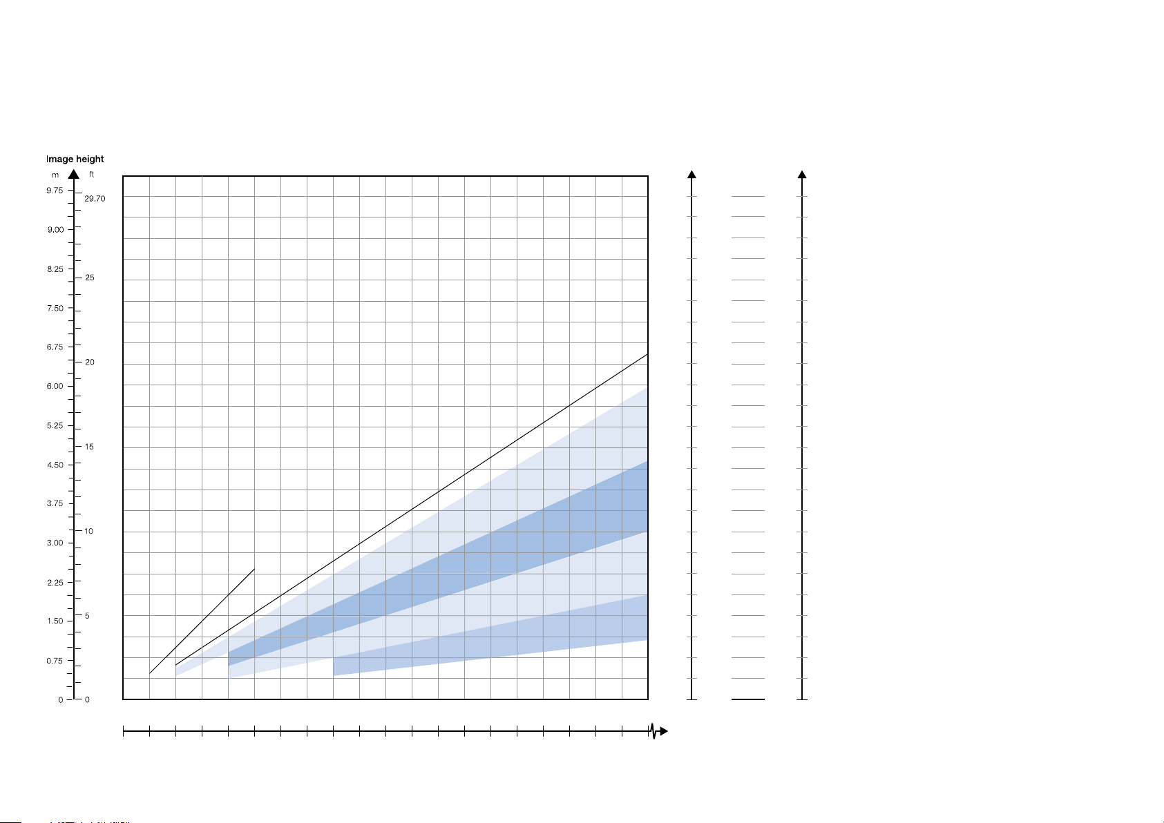
TECHNICAL DATA
S
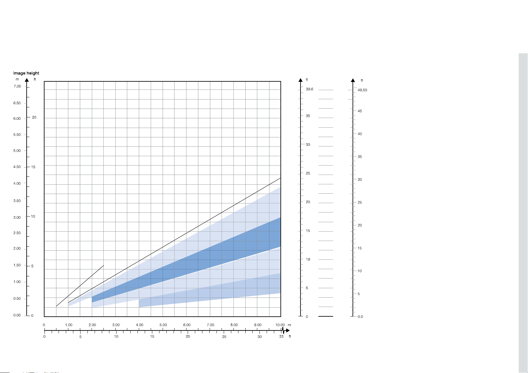
IMAGE SIZES BILDGRÖßE TAILLE D’IMAGE TAMAÑO DE PANTALLA
1400x1050
Wide Angle 1.25 : 1 (1.0 -15m)
Wide Angle Zoom 1.34 - 1.74 : 1 (1.0 - 15m)
Standard Zoom 1.74 - 2.51 : 1 (2.0 - 15m)
Tele Zoom 2.56 - 4.1 : 1 (2.0 - 30m)
Ultra Wide Angle 0.84 : 1 (0.5 - 2.5m)
0 1.00 2.00 3.00 4.00 5.00 6.00 7.00 8.00 9.00 10.00 m
Long Tele Zoom 4.1 - 7.1 : 1 (4.0 - 40m)
Image width
m
9.00
8.00
7.00
6.00
5.00
4.00
3.00
2.00
1.00
0
39.6
36.3
33.00
29.70
26.40
23.10
19.80
16.50
13.20
9.90
6.60
12.00
11.00
10.00
ft
3.3
0
creen diagonal
m
15.00
13.75
12.50
11.25
10.00
8,75
7.50
6.25
5.00
3.75
2.50
1.25
0
ft
49.50
65.18
41.25
37.13
33.00
28.88
24.75
20.63
16.50
12.38
8.25
4.13
0.0
Projection distance
0 3.30 6.60 9.90 13.20 16.50 19.80 23.10 26.40 29.70 33 .00 ft
86
Page 47

DECLARATIONS
english
FCC
FCC regulations provide that changes or modifications not expressly approved by the party
responsible manufacturer could void your authority to operate the equipment.
This device complies with part 15 of the FCC Rules. Operation is subject to the following two
conditions:
(1) This device may not cause harmful interference, and
(2) this device must accept any interference received, including interference that may cause
undesired operation.
Note: This equipment has been tested and found to comply with the limits for a Class B digital
device, pursuant to part 15 of the FCC Rules. These limits are designed to provide reasonable
protection against harmful interference in a residential installation. This equipment generates,
uses and can radiate radio frequency energy and, if not installed and used in accordance with
the instructions, may cause harmful interference to radio communications. However, there is no
guarantee that interference will not occur in a particular installation. If this equipment does cause
harmful interference to radio or television reception, which can be determined by turning the
equipment off and on, the user is encouraged to try to correct the interference by one or more of
the following measures:
Reorient or relocate the receiving antenna.
Increase the separation between the equipment and receiver.
Connect the equipment into an outlet on a circuit different from that to which the receiver is
connected.
Consult the dealer or an experienced radio/TV technician for help.
Changes or modifications made to this device which are not expressly approved by the party
responsible for compliance could void the user’s authority to operate the equipment.
CANADA
This Class B digital apparatus complies with Canadian ICES-003. / Cet appareil numérique de la
classe B est conforme à la norme NMB- 003 du Canada.
88
 Loading...