


INSTALLATION INSTRUCTIONS
Interactive Dry Erase Rear Projector Protection Guard
Instrucciones de instalación
Installationsanleitung
Instruções de Instalação
Istruzioni di installazione
Installatie-instructies
Instructions d´installation
Spanish Product Description
German Product Description
Portuguese Product Description
Italian Product Description
Dutch Product Description
French Product Description
11830027
11830027 Installation Instruc tions
DISCLAIMER
Milestone AV Technologies and its affiliated corporations and
subsidiaries (collectively “Milestone”), intend to make this
manual accurate and complete. However, Milestone makes no
claim that the information contained herein covers all details,
conditions or variations, nor does it provide for every possible
contingency in connection with the installation or use of this
product. The information contained in this document is subject
to change without notice or obligation of any kind. Milestone
makes no representation of warranty, expressed or implied,
regarding the in formation cont ai ned her ein. Mil estone assu mes
no responsibility for accuracy, completeness or sufficiency of
the information contained in this document.
Projecta® is a registered trademark of Milestone AV
Technologies. All rights reserved.
IMPORTANT SAFETY INSTRUCTIONS
WARNING: A WARNING alerts you to the possibility of
serious injury or death if you do not follow the inst ructions.
CAUTION: A CAUTION alerts you to the possibility of
damage or destruction of equipment if you do not follow the
corresponding instructions.
WARNING: Failure to read, thoroughly understand, and
follow all instructions can result in serious personal injury,
damage to equipment, or voiding of factory warranty! It is the
installer’s responsibility to make sure all components are
properly assembl ed and installed using the instructions
provided.
WARNING: Failure to provide adequat e structural strength
for this component can result in serious personal injury or
damage to equipment! It is the installer’s responsibility to
make sure the structure to which this component is attached
can support five times the combined weight of all equipment.
Reinforce the structure as required before installing the
component.
WARNING: Use this mounting system only for its intended
use as described in these instructions. Do not use
attachments not recommended by the manufacturer.
WARNING: Never operate this mounting system if it is
damaged. Return the mount ing system to a ser vice ce nter f or
examination and repair.
WARNING: Do not use this product outdoors.
--SAVE THESE INSTRUCTIONS--
2
Installation Instructions 11830027
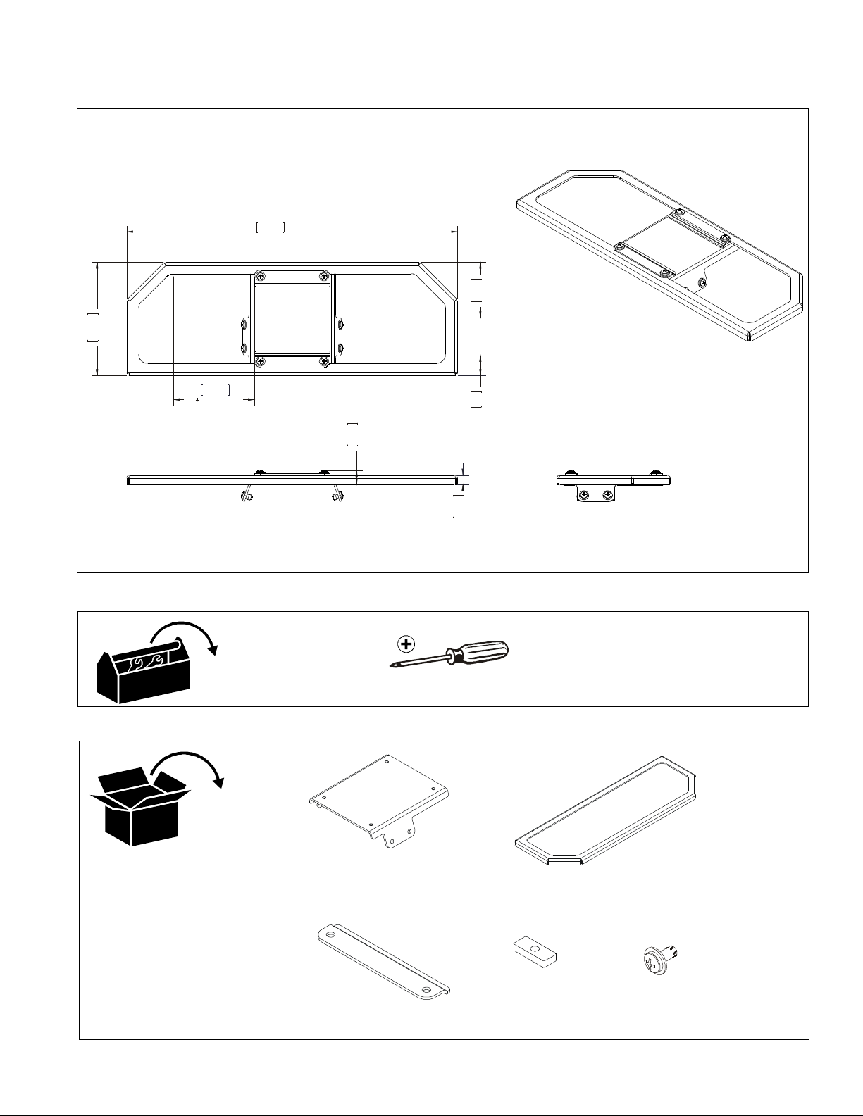
74.
6
17.50
2.9
4
444.527108.8
LATERAL SHIFT
12.
7
8
.
8
.
7
4
DIMENSIONS
6.00
152.4
4.28
1
0
TOOLS REQUIRED FOR INSTALLATION
PARTS
1.06
0.50
#2
A (1)
[guard base]
C (2)
[guard clamp]
D (4)
[slide nut]
B (1)
[guard bracket]
E (8)
#10-24 x 7/16”
3

11830027 Installation Instruc tions
LEGEND
Tighten Fastener
Apretar elemento de fijación
Befestigungsteil festziehen
Apertar fixador
Serrare il fissaggio
Bevestiging vastdraaien
Serrez les fixations
Loosen Fastener
Aflojar elemento de fijación
Befestigungsteil lösen
Desapertar fixador
Allentare il fissaggio
Bevestiging losdraaien
Desserrez les fixations
Phillips S cr ewdriver
Destornil lador Phillips
Kreuzschlitzschraubendreher
Chave de fendas Phillips
Cacciavite a stella
Kruiskopschroevendraaier
Tournevis à pointe cruciforme
Pencil Mark
Marcar con lápiz
Stiftmarkierung
Marcar com lápis
Segno a matita
Potloodmerkteken
Marquage au crayon
Drill Hole
Perforar
Bohrloch
Fazer furo
Praticare un foro
Gat boren
Percez un trou
Adjust
Ajustar
Einstellen
Ajustar
Regolare
Afstellen
Ajuster
Open-Ended Wrench
Llave de boca
Gabelschlüssel
Chave de bocas
Chiave a punte aperte
Steeksleutel
Clé à fourche
By Hand
A mano
Von Hand
Com a mão
A mano
Met de hand
À la main
Hex-Head Wrench
Llave de cabeza hexagonal
Sechskantschlüssel
Chave de cabeça sext avada
Chiave esagonale
Zeskantsleutel
Clé à tête hexagonal e
Remove
Quitar
Entfernen
Remover
Rimuovere
Verwijderen
Retirez
Optional
Opcional
Optional
Opcional
Opzionale
Optie
En option
Security Wrench
Llave de seguridad
Sicherheitsschlüssel
Chave de segurança
Chiave di sicurezza
Veiligheidssleutel
Clé de sécurité
4

Installation Instructions 11830027
Assembly And Installation
NOTE: The following installation instructions assume that
Projecta’s rear projector cart (part number 11630010)
has already been completely assembled. Do NOT
attempt to install this monitor arm to any other cart or
stand.
1. Use four #10-24 x 7/16” Phillips screws with captured
washers (E) and two guard clamps (C) to secure guard
bracket (B) to guard base (A). (See Figure 1)
1
(C) x 2
(E) x 4
3. Remove end cover from rear projector arm. (See Figure 3)
3
Figure 3
4. Slide assembled protection guard onto pro jector arm by
inserting sli de nuts ( D) int o cor res pondi ng gro oves on arm.
(See Figure 4)
5. Tighten screws whe n protecti on guard is in des ired positio n.
(See Figure 4)
6. Reinstall end cover to projector arm. (See Figure 4)
(A)
(B)
Figure 1
2. Loosely inst all remaining four # 10-24 x 7/16” Philli ps screws
with captured washers (E) through guard base (B) holes
and into four slide nuts (D). (See Figure 2)
(B)
2
(E) x 4
4
4
6
5
(E) x 4
Figure 4
Figure 2
(D) x 4
5

11830027 Installation Instruc tions
Adjustments
Lateral Shift
1. Loosen four sc rews holding gua rd bracket (B) to guar d base
(A). (See Figure 5)
2. Adjust guard br acket lat eral position as desir ed. (See Figure
5)
3. Tighten four s crews holding guar d bracket (B) to g uard base
when desired position is achieved. (See Figure 5)
1
2 3
Figure 5
2
6

Installation Instructions 11830027
7

11830027 Installation Instruc tions
8800-002436 Rev00
07/13
Projecta - Milestone AV Technologies B.V.
P.O. Box 191
6000 AD Weert, the Netherlands
Phone: +31 (0)495.580.850
Fax: +31 (0) 495.580.860
www.projectascreens.co.uk
emea.sales@milestone.com
 Loading...