

Page 1

BP1SL
Switch able (Ch.A or Ch.B)
Por ta ble Head set Sta tion
Op er at ing In struc tions & Con nec tions
The BP1SL is a sin gle-cir cuit beltpack which can mon i tor ei ther of two cir cuits, but not si mul ta neously. A front panel slide
switch per mits you to choose. It has a unique fea ture which pro vides a signal light for each chan nel and both lights are op er a tional no mat ter which cir cuit you are cur rently mon i tor ing. For si mul ta neous 2-cir cuit com mu ni ca tions see the BP2
1. Plug a head set into the XLR type 4-pin socket on the back of the unit. The rear panel con nec tions are de tailed on the
next page. In Pro In ter com sys tems, the phase of the ear phone is the re verse of that some times used. This was done to
re duce the ef fect that the head set con nec tor and wir ing has on the head set sta tion bridg ing im ped ance and ‘Sidetone’
(See #8) ad just ment sta bil ity. Ei ther stan dard of head set wir ing will work with Pro In ter com head set sta tions.
2. Plug the stan dard mi cro phone ca ble from your power sup ply or mas ter sta tion into each of the XLR 3-pin type sock ets
on the back of the unit.
3. Press the mic. but ton and partly turn up the ‘Lis ten level’ con trol on your unit and oth ers on the same cir cuits as
your self.
4. You should now be able to com mu ni cate with any of these other out sta tions.
5. The thumb op er ated ‘Lis ten-level’ con trol reg u lates the loud ness of your head set ear phone(s). It has NO ef fect on the
mi cro phone level, or the vol ume that oth ers hear.
6. The mi cro phone am pli fier gain is fac tory ad justed to suit most types of head set mi cro phones. It con tains a lim iter/com pres sor which com pen sates for dif fer ences in mi cro phone out put and voice lev els.
(Beltpack)
7. The flash (sig nal) push but ton flashes a light in all out sta tions con nected to your cir cuit. It is used to at tract at ten tion in
the event that a user has re moved his/her head set.
8. The screw driver pre set con trols the level of your own voice in your head set. This ad just ment is called ‘Sidetone’. This is
set at the fac tory at a level suit able to the ma jor ity of the us ers. This can be al tered for per sonal pref er ence or ad justed for
deep can cel la tion al low ing the head set to be re moved and used to mon i tor.
9. The BP1SL is com pat i ble with Clear-Com® and other, lesser-known 200W un bal anced party-line head set in ter com
sys tems.
Spec i fi ca tions:
Head set Mi cro phone Im ped ance: 200W dy namic, 30W to 1 KW ac cept able, or 1.2~1.8kW electret..
Head set Ear phone Im ped ance: 150-600W pre ferred, 8W - 4 KW ac cept able.
Volt age: 24V DC nom i nal, 18-30V DC ac cept able.
Cur rent con sump tion: 10 mA with speech, 30 mA with sig nal lamp ac ti vated.
Lamp type: 4-seg ment 20mA LED )
Line bridg ing im ped ance: 200W un bal anced
Sidetone can cel la tion: 0dB to 55dB
Con trols:
Chan nel se lec tor: Slide switch
Talk: Push on/push off, self in di cat ing switch
Lis ten level: Thumbwheel op er ated po ten ti om e ter
Sig nal: Non-latch ing push but ton switch.
Sidetone: Screw driver ad just, re cessed po ten ti om e ter.
(Con tin ued on next page)
Pro In ter com LLC
PO Box 7035 Al gon quin Il li nois 60102-7035
Phone: +1 (815) 680-5205 Or ders and Tech sup port: (888) 320-5928 Fax: +1 (815) 526-8689
Printed in USA
sup port@prointercomllc.com Skype: intercom4pros
Rev.3_01.13
Page 2
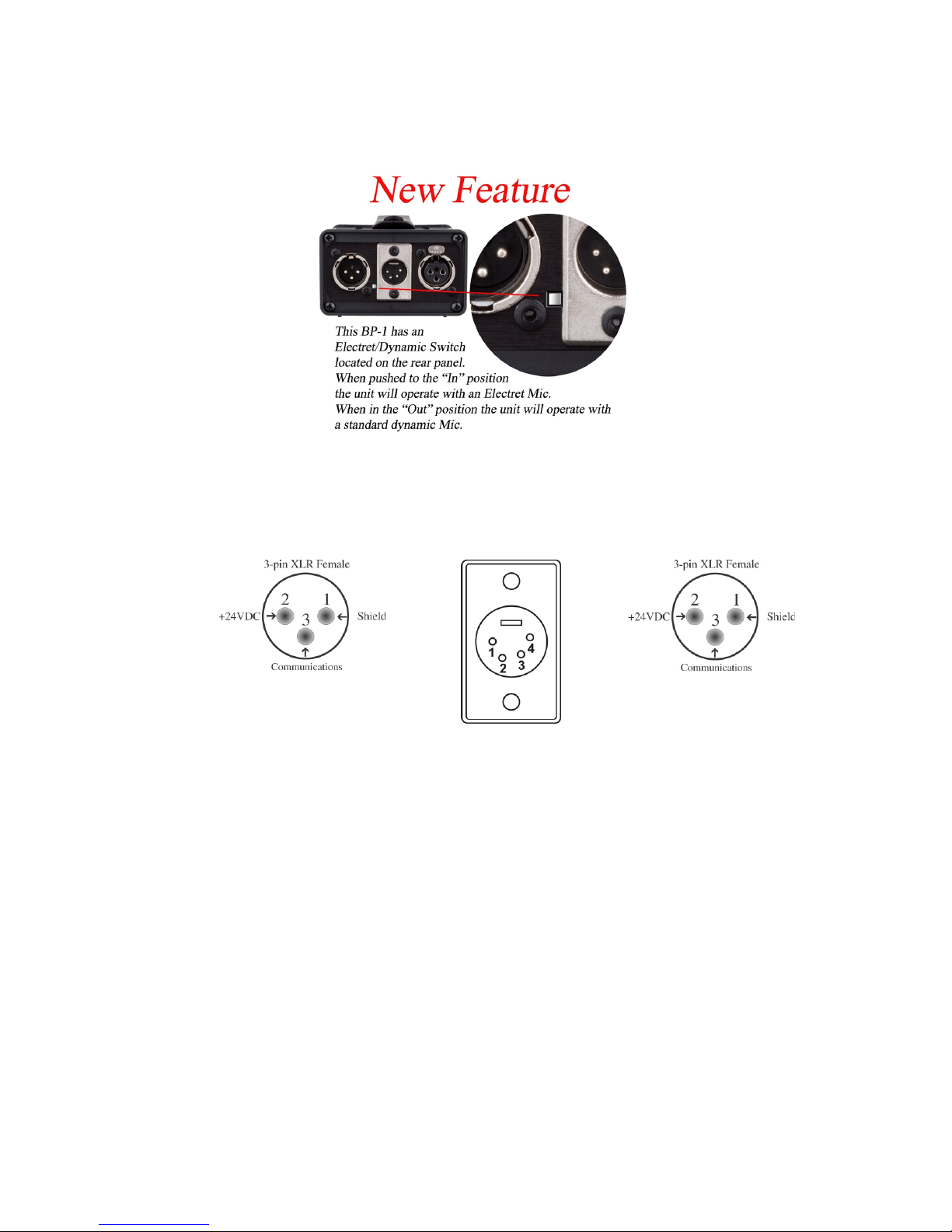
Now you can use head sets with electret
mi cro phones!
Rear (Back) Panel Con nec tions
4-pin Male XLR
Mic. Gnd. è
Mic. + è
Circuit B
ç Ear +
ç Ear 0
Circuit A
Head set
If you don’t read any thing else, please read this!!!
By con ven tion, in or der to avoid any con fu sion with low im ped ance mi cro phone jacks, the fe male jack on in ter com equip ment is con sid ered
the in put, while the male jack is in tended to be used to loop on wards to
other sta tions in the sys tem. Re vers ing this or der will not ef fect per for mance, but does make it more prob a ble that a re ver sal of pins 2 and 3
will oc cur. This is the sin gle most com mon cause of fail ure in both
beltpacks and in com plete in ter com sys tems. The re ver sal will ap ply
24VDC to the com mu ni ca tions con duc tor which will, at a min i mum,
cause the sig nal light sys tem to be come er ratic and even tu ally fail,
caus ing in ter nal dam age to the beltpack(s).
 Loading...