

Page 1
Member
Installation and Operation Guide for
PD1201 Inverter Remote Display
I. LIMITED WARRANTY: Progressive Dynamics Warrants its power inverters to be free from defects in material or workmanship under normal use and ser-
vice; and limits the remedies to repair or replacement.
II. DURATION: This warranty shall extend for a period of two years from the original date of purchase, and is valid only within the continental limits of the
United States and Canada.
III. WARRANTY EXCLUSIONS: This warranty does not apply to:
A. Any product which has been repaired or altered in any way by an unauthorized person or service station
B. Damage caused by excessive input voltage, misuse, negligence, or accident; or an external force
C. Any product which has been connected, installed, or adjusted or used other than in accordance with the instructions furnished, or has had the serial number
altered, defaced, or removed
D. Cost of all services performed in removing and reinstalling the power inverter
E. ANY LOST PROFITS, LOST SAVINGS, LOSS OF USE OF ENJOYMENT OR OTHERINCIDENTAL DAMAGES ARISING OUR OF THE USE OF,
OR INABILITY TO USE, THE PRODUCT. THIS INCLUDES DAMAGES TO PROPERTY AND, TO THE EXTENT PERMITTED BY LAW, DAM-
AGES FOR PERSONAL INJURY. THIS WARRANTY IN IN LIEU OF ALL OTHER WARRANTIES, INCLUDING WARRANTIES OF MER-
IV. PROOF OF PURCHASE: A warranty claim must be accompanied by proof of the date of purchase.
V. CLAIM PROCEDURE: Upon discovery of a defect, Progressive Dynamics shall be supplied the following information a the address listed below:
Upon determination that a warranty claim exists (a defect in material or workmanship occurring under normal use and service) the inverter shall be shipped postage
prepaid to Progressive Dynamics together with proof of purchase. The product will be repaired or replaced and returned postage prepaid.
507 Industrial Road
Marshall, MI 49068
CHANTABILITY AND FITNESS FOR A PARTICULAR PURPOSES.
A. Name and address of claimant
B. Name, model, and serial number of the product
C. Name year and model of the recreational vehicle in which the product was installed
D. Date of purchase
E. Complete description of the claimed defect
Mail Returns to: Progressive Dynamics
For Warranty Service Call: (269) 781-4242
Record the unit’s model and serial number in case you need provide this information in the future. It is
much easier to record this information now, instead of trying to gather it after the unit has been installed.
PD1201 (Remote Display)
© 2018 Progressive Dynamics Enterprises, LLC. All rights reserved.
Consult a licensed electrician or RV technician for installation assistance
Model: Serial Number:
See website www.progressivedyn.com
for more trouble shooting information and return instructions
Page 2
Included Items & Connecting the Remote
The PD1201 Remote Display is designed for use with all PD1200 Series Inverters. The remote will allow complete monitoring of your inverter. This guide will help you install and use the remote control to monitor the functions of your inverter.
NOICE: EQUIPMENT DAMAGE
This PD1201 Remote Display User Guide is in addition to, and incorporate by reference, the relevant product information for each product
in the PD1200 Series Inverter. Before reviewing this guide, you must read the relevant product manual. Unless specified, information on
safety, specifications, installation, and operation is as shown in the primary documentation. Ensure you are familiar with that information
before proceeding.
Failure to do follow these instruction will result in your inverter to not function properly.
Materials List
The PD1200 series inverter base package includes the
following items:
(1) PD1200 series inverter remote
(1) Owner’s guide & mounting template
(1) 25’ connection cable (included)
NOTE: If any of the items are missing, contact Progressive Dynamics for replacement.
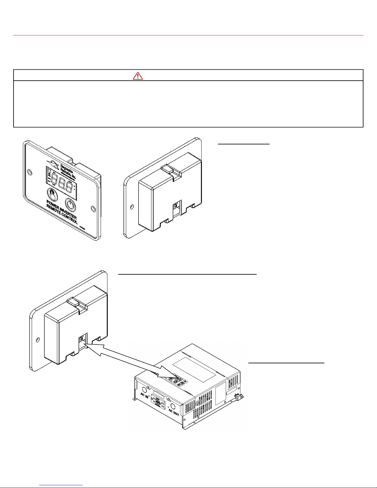
Figure 1 Inverter Remote (25’ communication cable not shown)
Connecting the remote to the inverter
Plug the connector plug into the port on the top of the inverter and the back of the remote
control using the supplied communication cable (see Figure 2). Failure to use the supplied
communication cable may result in damage to the PD1201 Remote Display.
It is recommended that you install the remote into the desired location prior to connecting
the cable to the remote and the inverter. Please refer to the installation portion of this guide
for those instructions.
Verifying connection
Once the remote display is securely connected to the PD1200 Series Inverter and the
inverter is turned on, it will begin displaying
readouts immediately. If your remote control
display does not begin to display information,
confirm that the communication cable is secured connected into both ports on the inverter and the remote control.
Figure 2 Connecting communication cable
Consult a licensed electrician or RV technician for installation assistance
Page 3
Using the Controls
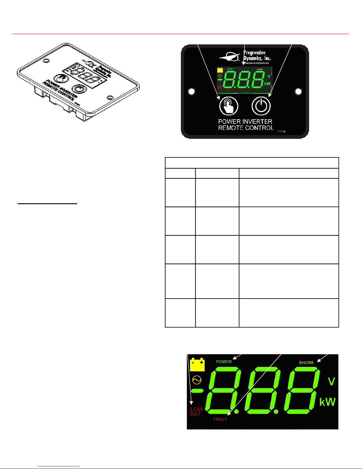
Figure 3 Inverter Remote Display
Display Features
Power Button: Press to turn on; hold to turn off
Select Button: Cycles between display states:
Input Voltage, Output Voltage, Output
Power, Sleep, Error Code (if applicable)
Power Indicator: Lights up green when the inverter is on
Fault Indicator: Flashes red when an error has occurred
Shore Indicator: Lights up yellow when AC input is detected
Low Bat Warning Indicator: Lights up red when the battery
is nearing the end of its charge
Sleep: Lights automatically dim after 30 seconds
Select Button
Figure 4 Remote Display Panel
ERROR CODES
Error Code Condition Description
Low battery voltage detected
E-1
High battery voltage shutdown
E-2
AC output overload shutdown
E-3
Over-temperature
shutdown
E-4
Input voltage has dropped beneath 10.5V for
several seconds. The PD1200 Series inverter
will automatically restart when the input
voltage reaches 12.0V.
Input voltage has surpassed 15.5V. The
PD1200 Series inverter will automatically
restart when the input voltage falls below
15.0V.
Output power has surpassed the continuous
power limit or the peak power limit. The
PD1200 Series inverter will not automatically restart. A manual restart is necessary
Internal temperature of the inverter has exceeded its safe operating limit. The PD1200
Series inverter will automatically restart
when internal temperatures return to safe
operating conditions.
Power Button Display
Consult a licensed electrician or RV technician for installation assistance
Internal Error An internal error has been detected. The
E-5
NOTE: For all error codes consult page 16 in the Installation and
Operation Guide for troubleshooting methods
PD1200 Series inverter will not automatically restart. A manual restart is necessary
Power Indicator Shore Power Indicator Low Bat Warning Indicator Fault Indicator
Figure 5 Display Indicators
Page 4
Installation Template
MOUNTING
HOLE
[101.64]
4.00
[73.03]
2.875
[69.89]
2.75
[57.15]
2.250
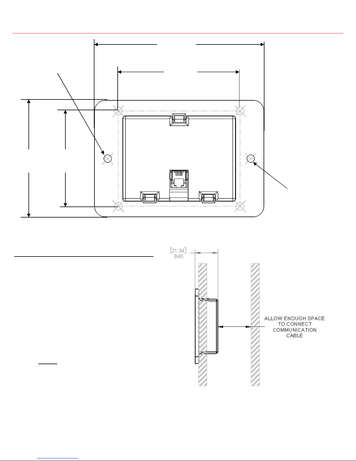
Figure 5 PD1201 Remote Display Mounting Template
Installing the remote display on the wall
1. Place the template on the wall.
2. Mark the corners (or trace the dotted lines) of the recess outline
on the wall.
3. Mark the two mounting holes for the two screws on the wall.
4. Remove the template from the wall.
5. Cut along the recess outlines on the wall to make a hole for the
remote control.
6. Pre-drill the mounting holes appropriate to the mount screws
(not provided) that will be used.
7. Connect the communication cable to the RJ9 port on the inverter
and the remote control (see Figure 2).
8. Mount the remote panel unit on the wall.
MOUNTING
HOLE
Note:
Ensure that there are no
Obstructions present, such as:
- Pipes
- Insulation
- Electrical Wiring
Ensure that there is at no less than 1” (25.4 mm) of space for communication cable.
Consult a licensed electrician or RV technician for installation assistance
Figure 6 Mounting Diagram
 Loading...