

Page 1
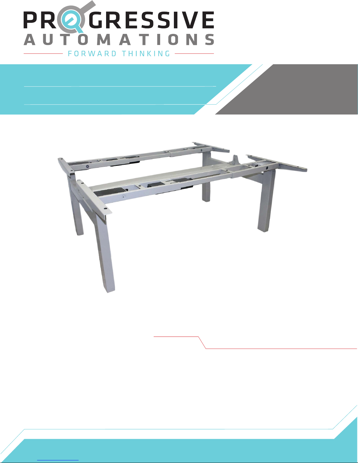
FLT-08
User Manual
Contents
Caution/Liability
Technical Specifications
Parts
Assembly Instructions
Operational/Reset Procedure,
Troubleshooting
Dimensions
Page 2
Page 3
Page 4
Page 5-6
Page 7
Page 8
Page 2
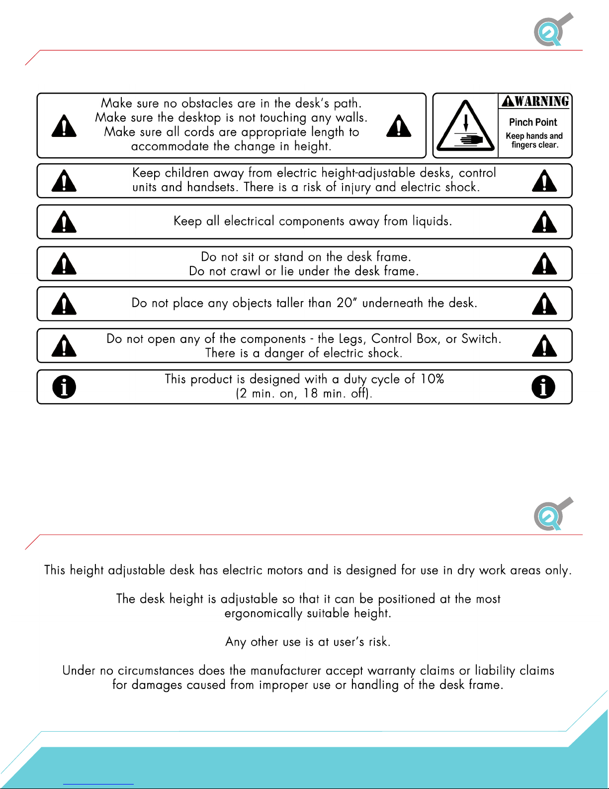
Caution
Liability
2
Page 3

Technical Specifications
Input Voltage
Output Voltage
Stroke
Weight Capacity
Speed
Height Range
Duty Cycle
Material
Certification
Base Width
120 VAC, 60 Hz
24 VDC
25.5"
220 lbs per set
1.5"/sec
23.5” - 49” (without table top)
10% Max. 2 mins on, 18 mins off
Steel
UL
43” min. - 74” max. (55.3" with Cable Tray installed)
Minimum Table Top Size
Features
43"x 24” (per set)
Soft start/stop, adjustable leveling studs & 4 memory presets
3
Page 4
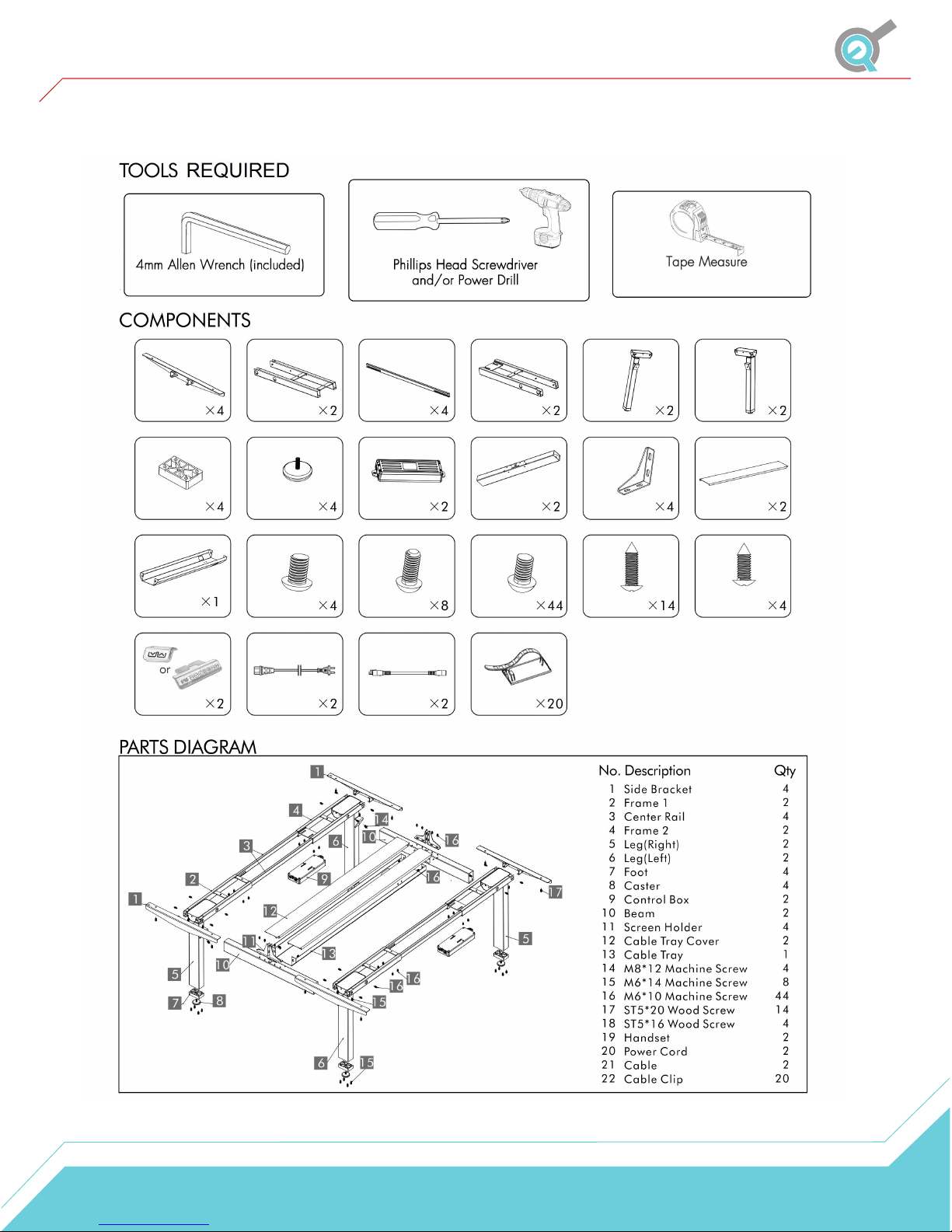
Parts
Side Bracket
Foot
Cable Tray
Handset
Frame 1
Caster
M8x12 Machine
Screw
Power Cord
Center Rail Frame 2
Control Box
M6x14 Machine
Screw
Cable
Beam
M6x10 Machine
Screw
Cable Clip
Leg
(Right)
Screen Holder
ST5x20 Wood
Screw
Leg
(Left)
Cable Tray
Cover
St5x116 Wood
Screw
4
Page 5
Assembly Instructions
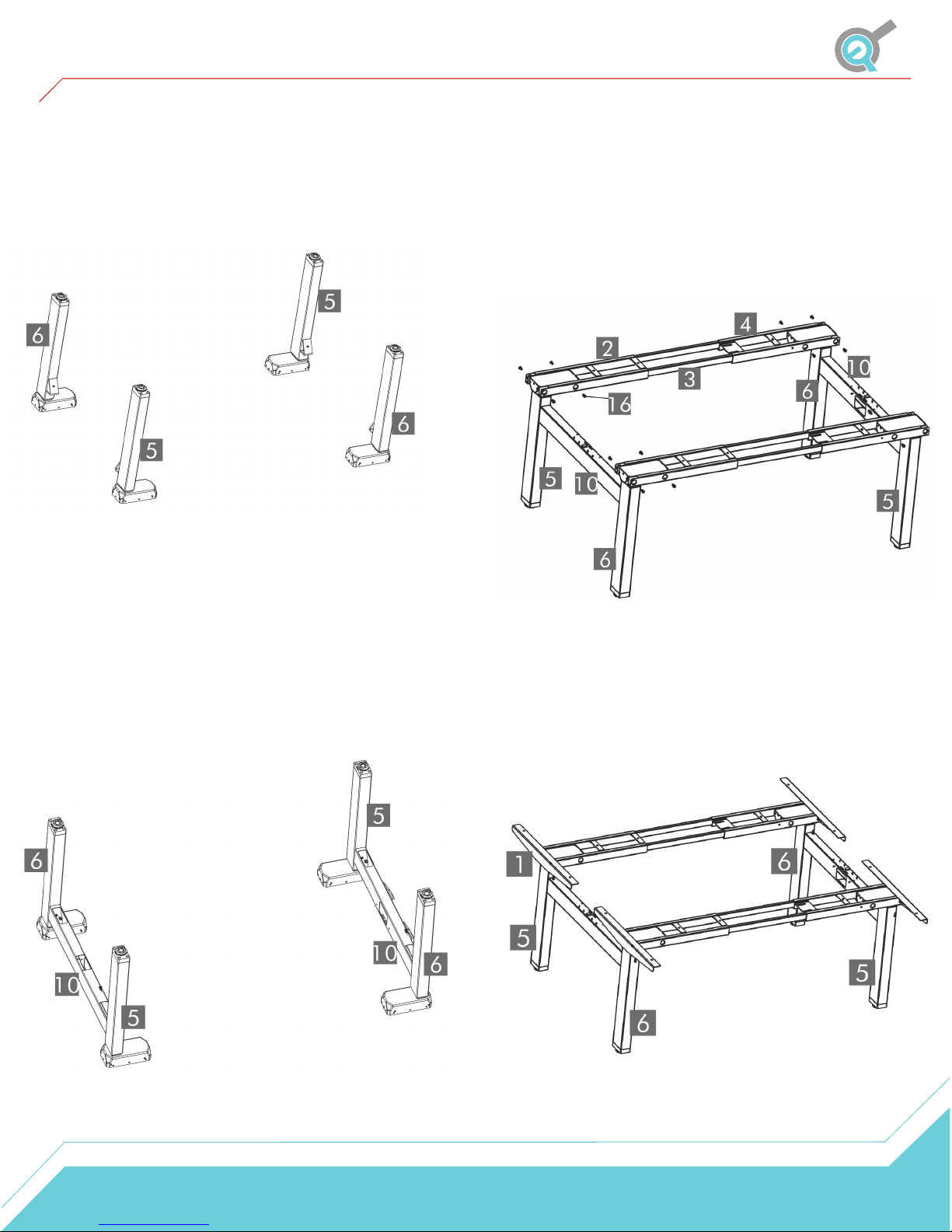
STEP 1
Prepare the four legs (5 & 6) as shown in the
picture below.
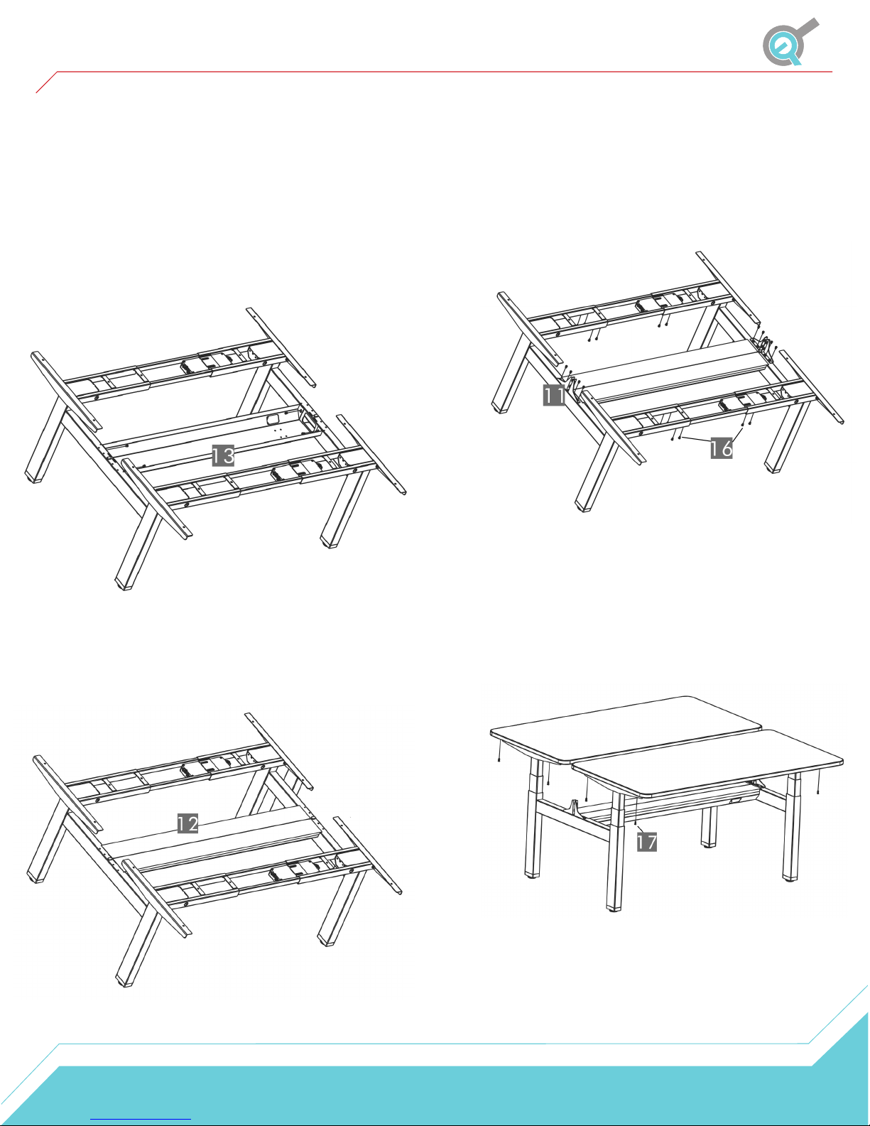
STEP 3
Use 16 of the M6x10 Machine Screws (16) to attach the
Frames to the Legs. Put the Center Rails (3) into the Frames
as shown in the picture below.
*Please note that while the picture shows the table lift set
flipped over, we do not recommend flipping it until Step 5*
STEP 2
Using the supplied Allen Wrench, insert four M8x12 Machine
(14) Screws to attach the Beams (10) to the legs as shown in the
picture below.
STEP 4
Slide the Side Brackets (1) into the Frames. Use eight of
the M6x14 Screws to attach the Side Brackets to the
Frames.
5
Page 6
Assembly Instructions
STEP 5 (optional)
Insert four of the M6x10 Machine Screws into the holes of
the Beams then assemble the Cable Tray as shown in the
picture below.
*Please note that once you install the Cable Tray, the base
width will be locked in that position. If you'd like to adjust
the base width, skip to step 7*
STEP 7
Use 24 of the M6x10 Machine Screws to
attach the Center Rails to the Frames and to
attach the Screen Holders (11).
STEP 6
Place the Cable Cover Tray (12) on top of the
Cable as shown in the picture below.
STEP 8
Use the ST5x20 Wood Screws to attach your two
table tops (sold separately) to the assembled table lift
set. Please ensure this is enough space between the
table tops so they do not over lap one another.
STEP 9
Connect the Cables and attach the Hand Remotes
to the table tops. Position them wherever you want.
6
Page 7

Operational Procedure
Once your table lift is installed, operation is simple. Using the wired remote will allow full control over
extending and retracting the lift columns. Use the up button to raise the table lift and the down button
to lower the table lift.
You can program up to 4 locations using the memory setup: Use the up/down buttons on the remote to
find your desired height(s), then press “M” followed by a number 1-4. The table height position is now
saved. To move to the set position, hold the number button.
Reset Procedure
IMPORTANT
You must reset the desk prior to use:
To reset, press and hold the DOWN button on the Hand Remote (7) until the table lift reaches its
lowest point. Release the DOWN button. Press and hold the DOWN button again until the LED display
shows "RST". If you are not using an LED hand remote hold it for about 10 seconds. Release the
DOWN button. Finally press and hold the DOWN button once more until the table lift lowers, slightly
rises then stops. This signals the end of the reset procedure. Release the DOWN button and your table
lift is now ready to use.
Troubleshooting
If your desk is not functioning it might need to be reset. Follow the RESET procedure.
If your hand remote has an LED display and it displays "RST" (reset), perform the reset procedure.
If the LED displays shows an error message ("Er1" - "Er13"), confirm that all wired connections are
secure. Then perform the reset procedure.
If the LED remote displays "HOT", let the unit cool down for 20 minutes.
If the error message persists after the reset procedure, contact us at 1-800-676-6123 or
[email protected].
7
Page 8
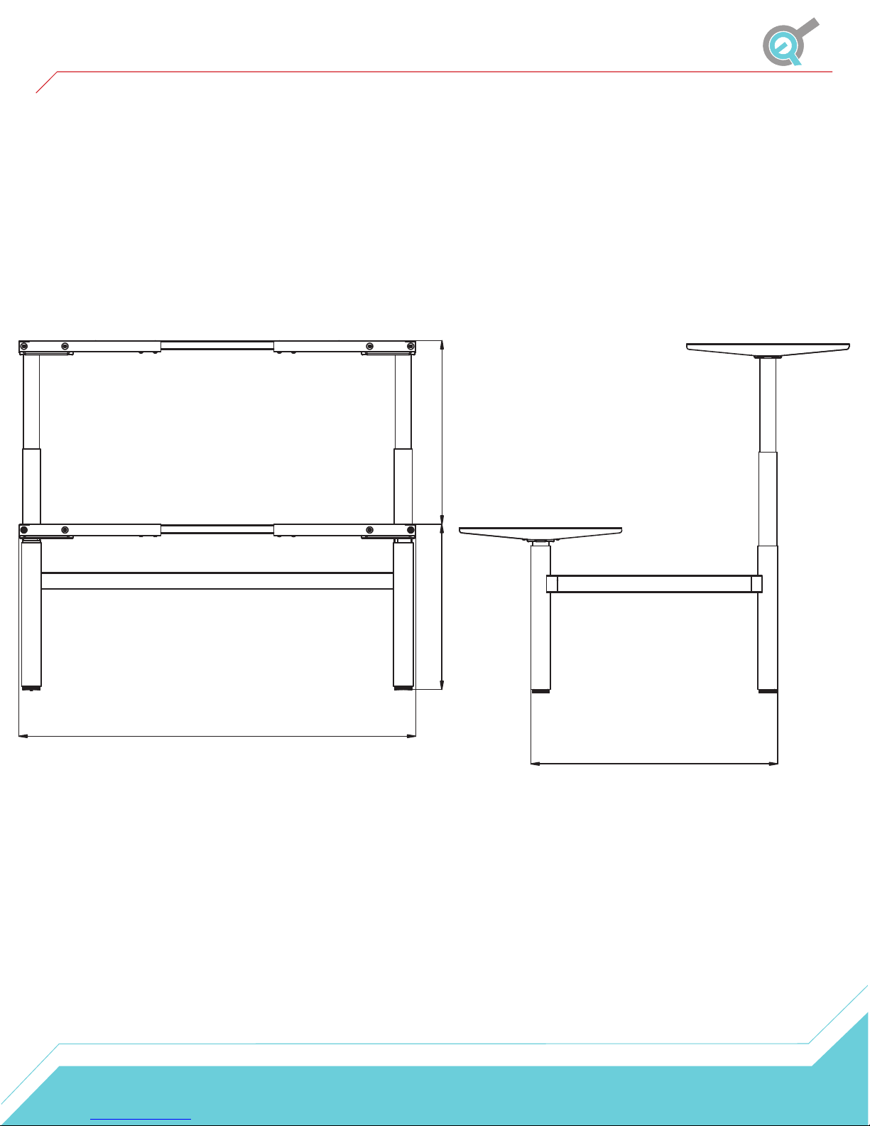
Dimensions
25.5"
55.3" with Cable Tray
23.5"
34.4"
8
 Loading...