

Page 1
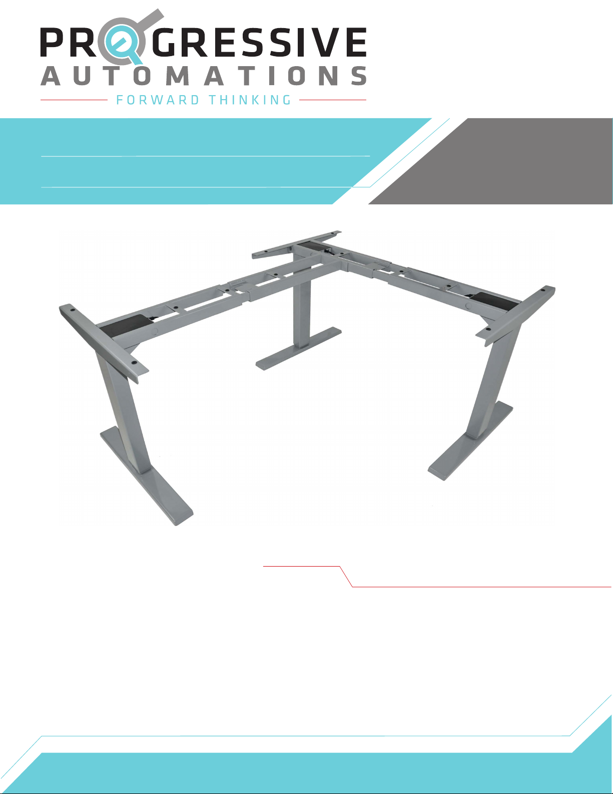
FLT-05
User Manual
Contents
Caution
Specifications
Dimensional Drawing
Components
Assembly
Operation
Reset Procedure
Troubleshooting
1
2
3
4
5-6
7
7
8
Page 2
Caution
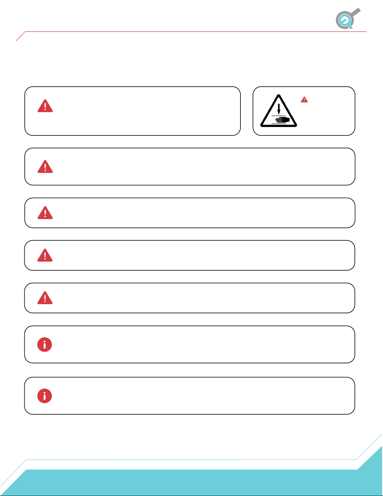
Ensure no obstacles are in the table lift's path. Ensure the
tabletop is not touching any walls. Ensure all cords are
appropriate length to accommodate the change in height.
Keep children away from electric height-adjustable table lifts, control units, and handsets. There
is a risk of injury and electric shock.
Keep all electrical components away from liquids.
Do not sit or stand on the table lift. Do not crawl or lie under the table lift.
Warning
Pinch Point
Keep hands and
fingers clear.
Do not place any objects taller than 20" underneath the table lift.
During the Reset Procedure, the table lift will retract 7mm below the lowest normal
operating height, ensure no obstacles impede this motion of travel.
Under no circumstances does the manufacturer accept warranty claims or liability claims for
damages caused by improper use or handling of the table lift.
1
Page 3
Specifications
Input Voltage 120VAC, 60 Hz
Output Voltage 24VDC
Stroke (movement) 25.5"
Height Range (without tabletop) 23.5” - 49”
Weight Capacity (load) 330 lbs (110 lbs per leg)
No Load Speed 1.57"/s
Full Load Speed 1.18"/s
Duty Cycle 10% (2 minutes on, 18 minutes off)
Operating Noise < 50 dB
Frame Material SPCC/ SPHC Steel
Finish Powder Coat - Grey(RAL7045)
Leveling Adjustable Leveling Feet
Low Power Mode Standby < 0.1W
Certification UL and BIFMA United Certificate
Feature Description
Soft Start and Stop
Memory Presets
The table lift will accelerate to maximum speed
and decelerate to a stop to ensure smooth travel.
The Smart Remote has the ability to save preset height locations
for convenience. Set the numbered buttons on the Smart Remote
for quick and seamless adjustment.
Anti-Collision
The Anti-Collision feature will help protect the table lift against obstacles
which impede the motion of travel. There are 3 force settings which can
be detected during travel, 22lbs, 33lbs, and 44lbs.
2
Page 4
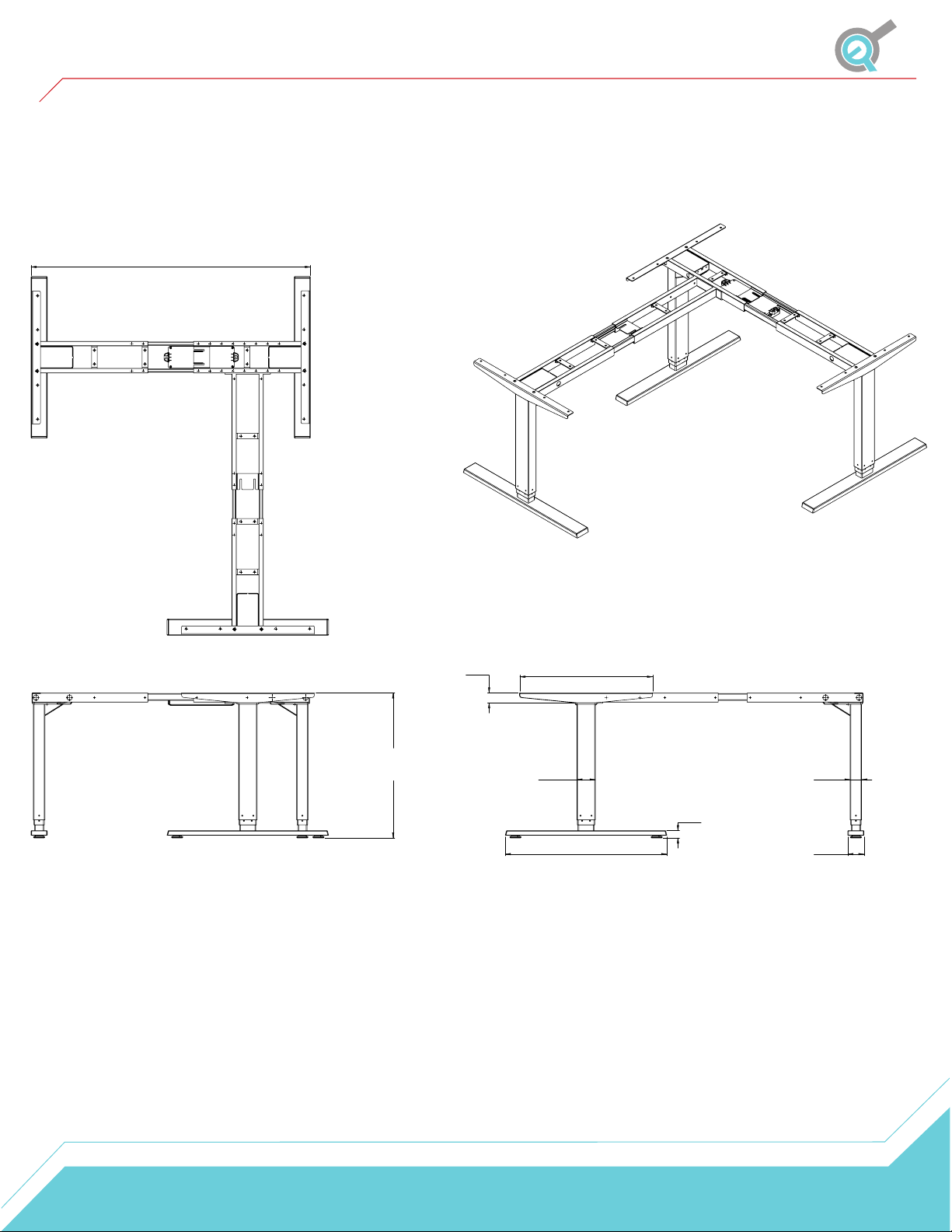
Dimensional Drawing
Maximum Width - 72.6"
Minimum Width - 42.7"
Extended - 49.0"
Retracted - 23.5"
1.7"
3.1"
22.6"
2.0"
1.3"
27.6"
2.8"
*Feet and column style may vary slightly
3
Page 5
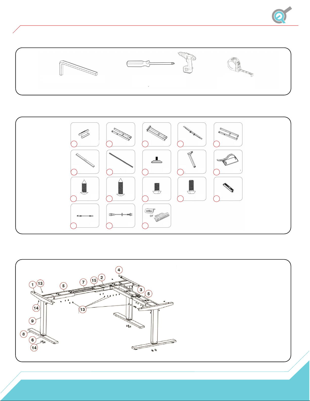
Components
Tools
Parts
4mm Allen Wrench (included)
1
66 7
1
11
11
1
16
16
x12
x2
x2
12
12 13
17
17 18
Phillips Head Screwdriver
and/or Power Drill
2
2 3
x1 x1 x3 x2
x12
4 5
8 9 10
x32
14 15
x18
x1x1
Tape Measure
x16x3x6x4x3
x1
Parts List
NO.
1
2
3
4
5
6
7
8
9
10
11
12
13
14
15
16
17
18
Description
Rubber Block
Frame 1
Frame 2
Side Bracket
Frame 3
Foot
Ceter Rail
Caster
Leg
Cable Clip
ST5x16 Wood Screw
ST5x20 Wood Screw
M6x10 Machine Screw
M6x14 Machine Screw
Control Box
Cable (1.3m)
Power Cord
Handset
Qty
12
1
1
3
2
3
4
6
3
16
2
12
32
18
1
2
1
1
4
Page 6
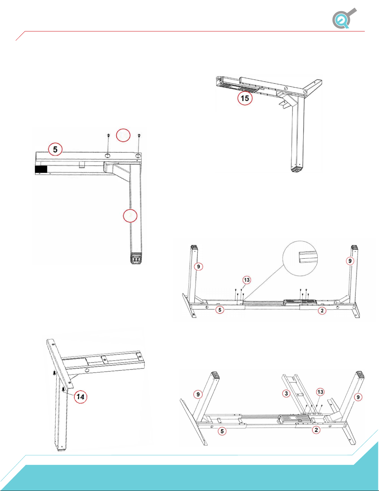
Assembly
STEP 1
Place one of the Legs (9) into Frame 3 (5). Line up the
holes on the Leg (9) with the holes on Frame 3 (5).
Using the supplied Allen Wrench, insert four M6x 10
Machine Screws (13) through the holes in the Frame
(5), going into the Leg (9) and rotate each screw just a
few times. After all four screws are inserted, tighten
them all.
Follow these steps for the other two Legs (9) and
other Frames (2,5).
13
• •
9
STEP 3
The Frame 1 (2) should be placed on the side of the
desk where you plan to mount the Control Box (15).
Slide the Control Box into the Frame (2).
STEP 4
Slide the two Center Rails (7) into the two Frames (2,5)
ensuring that the slots in the Center Rails face inward
and are closer to the top edge when the assembly is
upside down (see image).
Lock the position of the Center Rails (7) using eight
M6x10 Machine Screws (13).
•
STEP 2
Choose the appropriate Side Bracket (4) and slide it
into the Frame (5). Insert two M6x14 Machine
Screws (14) through the two holes in the top of the
side bracket going into the frame end. Using the
supplied Allen Wrench, rotate each screw just a few
turns. After both machine screws are inserted,
tighten them both. Do the same fo the other frame
ends.
STEP 5
Using four M6x10 Machine Screws (13) to link Frame 2
(3) and Frame 1 (2) as shown in the image beow.
5
Page 7
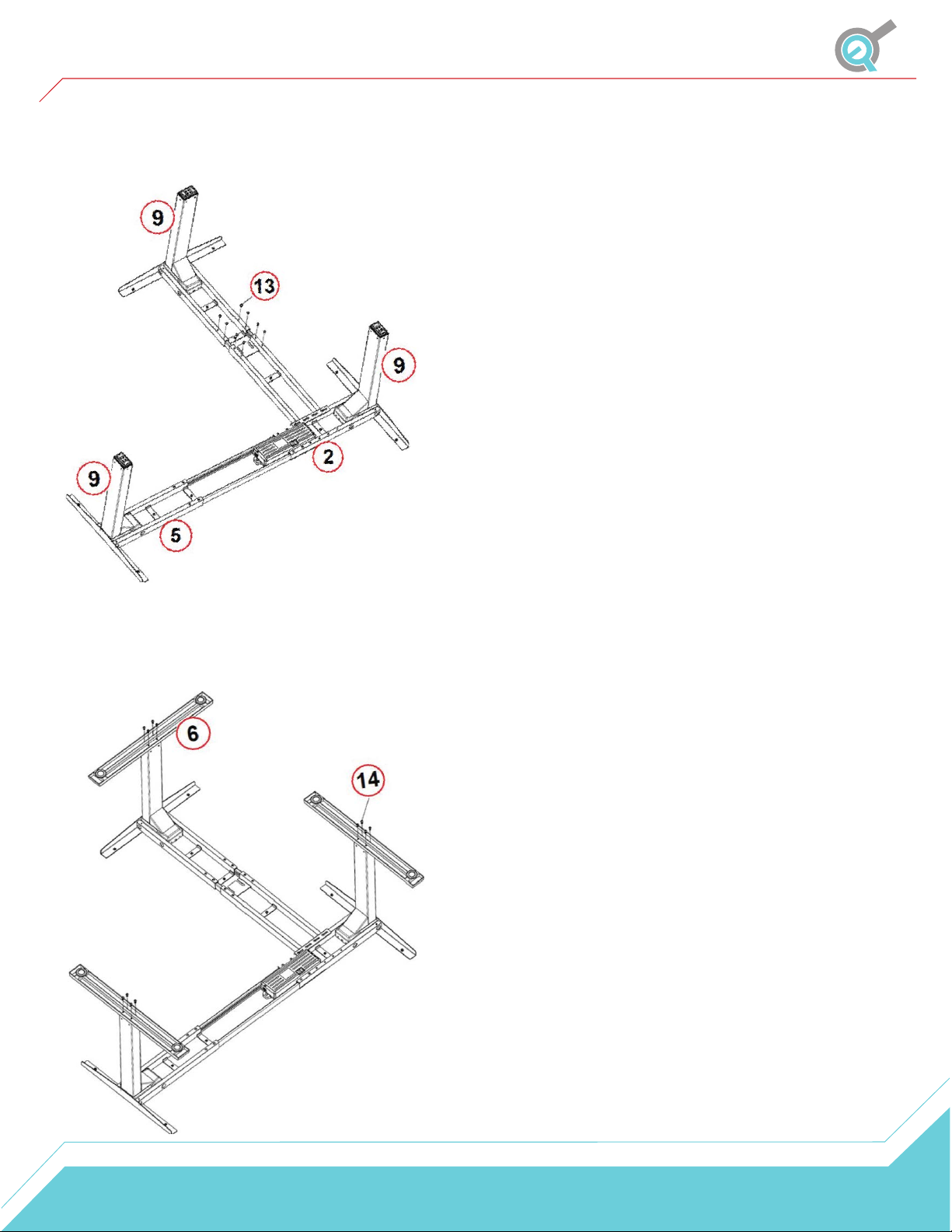
Assembly
STEP 6
Lock in the position of the Center Rails (7) using eight
M6x10 Machine Screws (13) as shown in the image below.
STEP 8
We recommend having at least two people for this
step. Grab the base (the legs) of the assembled frame
and turn it right side up.
STEP 9
Plug the Power Cord (17) into a 110V outlet and plug
in all three cables from the Legs into the Control Box.
Use the two Cables (16) for the two farthest legs. It is
now ready for use.
IMPORTANT
Prior to normal operation, please complete a Reset
Procedure outlined in the next section.
STEP 7
Attach each Foot (6) with four M6x14 Machine Screws (14)
and tighten them in a cross-pattern.
6
Page 8
Operation
Normal Operation
Using the wired remote, press and hold the 'Up' button to raise the table lift. To lower the table lift, press and hold
the 'Down' button. The 'Up' and 'Down' buttons are momentary controlled, when they are released, the table lift will
stop immediately.
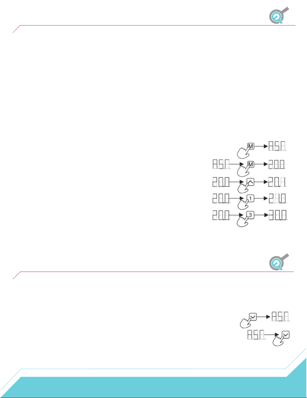
To set a preset location, move the table lift to the desired height. Press the 'M' button followed by a numbered
button. The LED display will flash an 'S', followed by an 'S - Number'. This will indicate that the preset has been saved.
To use a preset, press any of the numbered buttons and the table lift will begin to move to the preset position. It is
important to ensure that no obstacles impede the motion of travel. To stop the table lift, press any button.
If the table lift does not function as intended or the LED display flashes "RSt", please follow the Reset Procedure
outlined in the next section.
Setting the LED Display
Using the wired smart remote, retract the table lift to the lowest position. Press and
hold the 'Down' button again until the LED display flashes "RST".
Press and hold the 'M' button until the LED display flashes the starting height (if
the display returns to "RSt" before the next step, repeat this step).
To change the value of the starting height, use the 'Up', 'Down' to increase and
decrease by 0.1. Use the '1', '2' to increase and decrease by 1s. Use the '3', and '4'
buttons to increase or decrease by 10s.
Once the correct value is displayed, wait 5 seconds until the LED display flashes
"RSt". Follow the Reset Procedure outlined in the next section to save the new
starting height.
Note: the LED display has a tolerance of ±0.1.
Reset Procedure
WARNING: During the Reset Procedure, the table lift will retract 7mm below the lowest normal operating height,
please ensure that no obstacles impede this motion of travel.
1. Move the table lift to the lowest position. (If there is an 'RSt' displayed on the remote, continue
to step 3.)
2. To initiate the Reset Procedure, press and hold the down button on the remote until "ASr" is
displayed. Release the down button.
3. Press and hold the down button on the remote, the table lift will begin to retract 7mm lower
than the lowest normal operating height. To stop motion at any time, let go of the down button.
4. Once the table lift has completed the Reset Procedure, height will be displayed on the remote.
7
Page 9
Troubleshooting
Problem Possible Cause Corrective Action
Low power mode
Remote LED is off.
activated
Connection issue
Troubleshooting Guide
Press any button on the remote and LED will activate.
Disconnect and reconnect the RJ-45 remote connector. Ensure connection is
secure and cable is not damaged.
Table lift does not
move when motion
control buttons are
pressed.
Table lift travels at a
significantly slower
speed than rated
specification.
Unusual noise during
travel.
Table lift stops abruptly
during travel.
Table lift is not level. Out of sync
Limit switch reached
Connection issue
Weight issue Ensure weight capacity has not exceeded the maximum load rating.
Weight issue Ensure weight capacity has not exceeded the maximum load rating.
Obstacle
Follow "Setting Limit Switches" instructions to remove the programmed limit. If
maximum or minimum height limit has been reached, please move the system
in the opposite direction.
Disconnect and reconnect the Lifting Columns, Control Box, AC Power, and
Remote.
Ensure there are no obstacles in the path of the table lift. If the movement
continues to fail, initiate the Reset Procedure.
Disconnect and reconnect all cables (Lifting Column, Control Box, AC Power,
and Remote), then initiate the Reset Procedure.
Error Codes (remotes with LED display)
Error Code Error Summary Description
E01 M1 overcurrent protection
E02 M2 overcurrent protection
E03 M3 overcurrent protection
E04 M4 overcurrent protection
All columns stop moving and remote displays E01-E04. Ensure that the total
weight capacity of the table lift has not been exceeded and that no obstacles
obstruct the movement. Press any key and remote will display
RST, initiate the Reset Procedure. If the issue persists, disconnect and
reconnect all of the lifting columns, including the main power. Repeat the Reset
Procedure.
E07 M1 hall error
E08 M2 hall error
E09 M3 hall error
E10 M4 hall error
H01
Over heat /duty cycle
protection
All columns stop moving and remote displays E07-E10. Ensure that all columns
are still properly connected to the control box. Check to see if any cables have
been damaged. Press any key and remote will display RST, initiate the Reset
Procedure. If the issue persists, disconnect and reconnect all of the lifting
columns, including the main power. Repeat the Reset Procedure.
All columns stop moving, remote displays H01 (if LED screen available). Allow
the system to rest for 16 minutes, use normally. Follow the Duty Cycle rating to
ensure no issues arise from overheating.
8
 Loading...