

Page 1
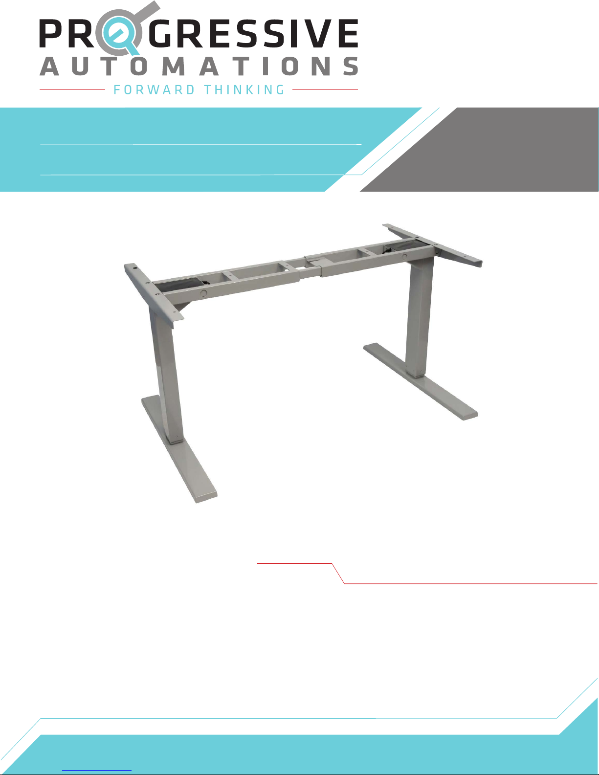
FLT-02
User Manual
Contents
Caution/Liability
Technical Specifications
Parts
Assembly Instructions
Operational/Reset Procedure,
Troubleshooting
Dimensions
Page 2
Page 3
Page 4
Page 5-7
Page 8
Page 9
Page 2
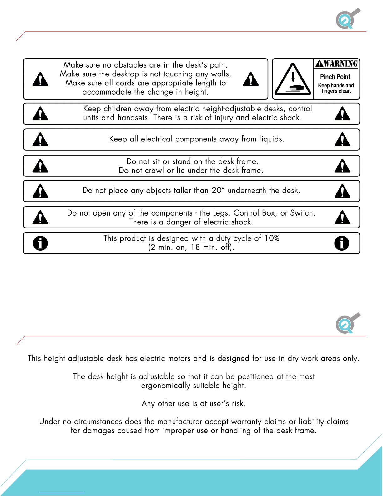
Caution
Liability
2
Page 3

Technical Specifications
Input Voltage
Output Voltage
Stroke
Weight Capacity
Speed
Height Range
Duty Cycle
Material
Certification
Base Width
120 VAC, 60 Hz
24 VDC
25.5"
270lbs (135 lbs Per Leg)
1.30"/sec
23.5” - 49” (without table top)
10% Max. 2 mins on, 18 mins off
Steel
UL
43” min. - 72.4” max.
Minimum Table Top Size
Color Options
Features
43"x 24”
Grey, black, or white
Soft start/stop, adjustable leveling studs & 4 memory presets
3
Page 4
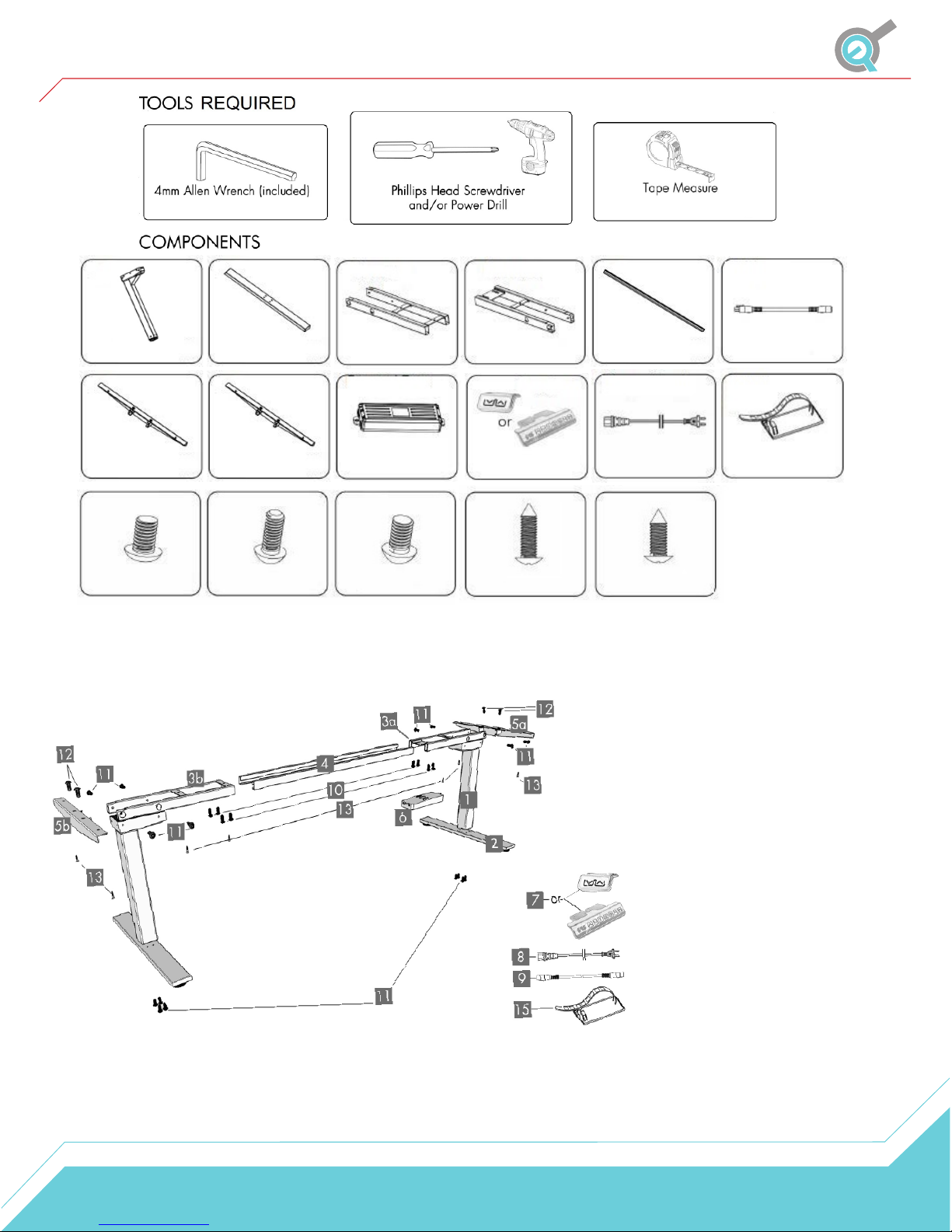
Parts
Legs
x2
Side Bracket A
M6x10 Machine
Screw
x8
Foot
x2
Side Bracket B
M6x14 Machine
Screw
x16
Frame End-CB
Control Box
M6x35 Machine
Screw
x4
Frame End
Remote
M5x20 Wood
Screw
x7
Center Rail x2
Power Cord
M5x16 Wood
Screw
x2
NO.
1
2
3a
3b
4
5a
5b
6
7
8
9
10
11
12
13
14
15
Cable
Cable Clip
Components
Leg
Foot
Frame End CB
Frame End
Center Rail
Side Bracket A
Side Bracket B
Control Box
Handset
Power Cord
Cable
M6x10 Machine Screw
M6x14 Machine Screw
M6x35 Machine Screw
M5x20 Wood Screw
M5x16 Wood Screw
Cable Clip
x10
Qty
2
2
1
1
2
1
1
1
1
1
1
8
16
4
7
2
10
4
Page 5
Assembly Instructions
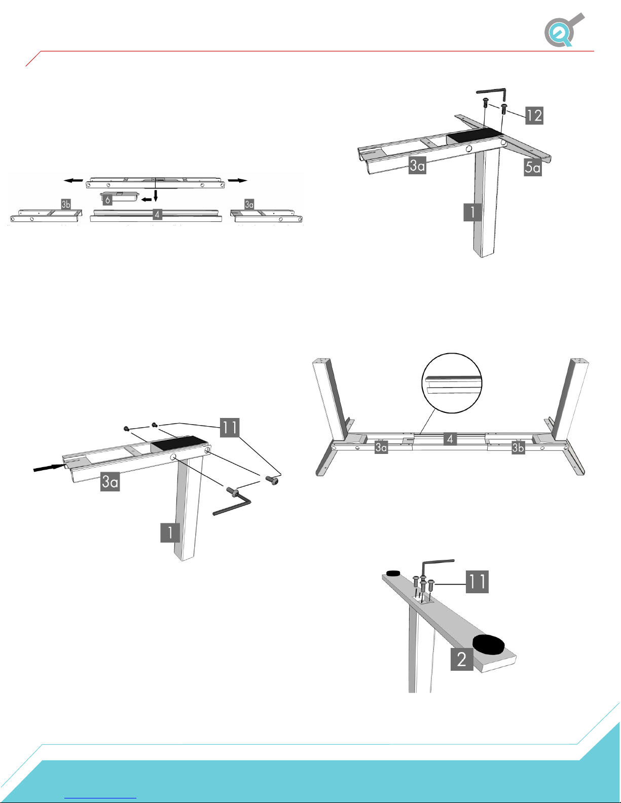
STEP 1
Before you start make sure to lay out all the
components and hardware to ensure you have all the
necessary parts listed on the parts page. Separate the
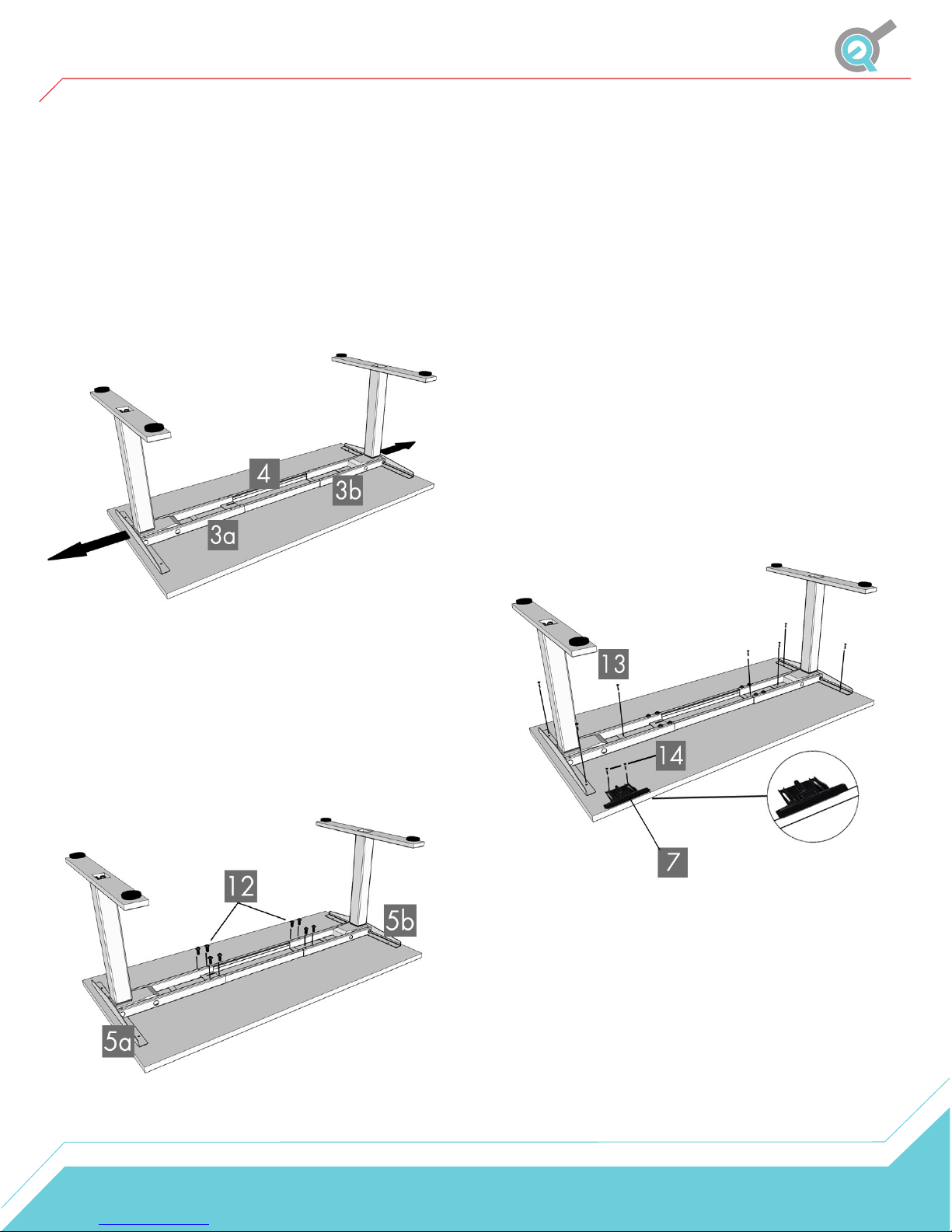
Frame Ends
(3a,3b) and you will find the Center Rails (4) inside.
STEP 2
Place one of the Legs (1) into the Frame End-CB (3a)
making sure that the bar is on the top side in relation to the
(Leg 1) Then line up the holes on each Leg (1) with the
holes on the Frame End-CB (3a)
Insert four M6x14 Machine Screws (11) through the
holes on the Frame End-CB (3a) going into the Leg (1).
Rotate each screw with the supplied Allen Wrench just a
few turns, then once all four are inserted you can tighten
them until secure. Do this for both Legs.
STEP 4
Slide the two Center Rails (4) into the two Frame Ends
(3a,3b). Make sure the slots in the Center Rails are
facing inward and that they are closer to the top edge
when the assembled unit is upside down (see picture
below).
STEP 3
Take a Side Bracket (5a or 5b) and slide it into the
Frame End-CB (3a). Insert two of the M6x35 Machine
Screws (12) through the two holes in the top of the
Side Bracket. Use the supplied Allen Wrench to rotate
each screw a few turns. Once both the screws are
inserted, tighten until secure. Repeat this process for
both legs.
STEP 5
Attach a Foot (2) with four M6x14 Machine Screws (11)
and tighten until secure in a cross-pattern. Repeat this
process for both legs.
5
Page 6
Assembly Instructions
STEP 6
Depending on your desktop, it may or may not be predrilled. Make sure to check both sides of the desktop
before placing the assembled unit on the underside of
your desktop.
Adjust the width of the unit to fit your desktop by
sliding the two halves apart. We recommend to leave
at least a half inch of the desktop extending beyond
the assembled frame. Make sure to center the Side
Brackets (5a,5b).
STEP 8
Make sure that the wood screws are not too long for your
desktop, otherwise they will puncture the surface once
screwed all the way in.
We recommend that you pre-drill any holes needed for
fasteners if your desktop is not pre-drilled already. Do not
use countersunk screws.
Make sure the assembled unit is positioned properly on
the underside of your desktop. Attach the unit to the
underside of your desktop using seven of the M5x20
Wood Screws (13).
Attach the Hand Remote (7) so the front of the remote is
lined up with the desktop edge. Place the remote
anywhere along the edge so that you'll have easy access
to it. Use two of the M5x16 Wood Screws (14) to attach
and secure the remote to the desktop.
Make sure you do not over-tighten the screws. Doing so
could cause damage to the components.
STEP 7
If your desktop is pre-drilled skip ahead to Step 8. If
your desktop is not pre-drilled, lock the position of
the Center Rails using eight of the M6x10 Machine
Screws (10).
Make sure the screws contact the Center Rails (4)
by sliding them as needed.
6
Page 7
Assembly Instructions
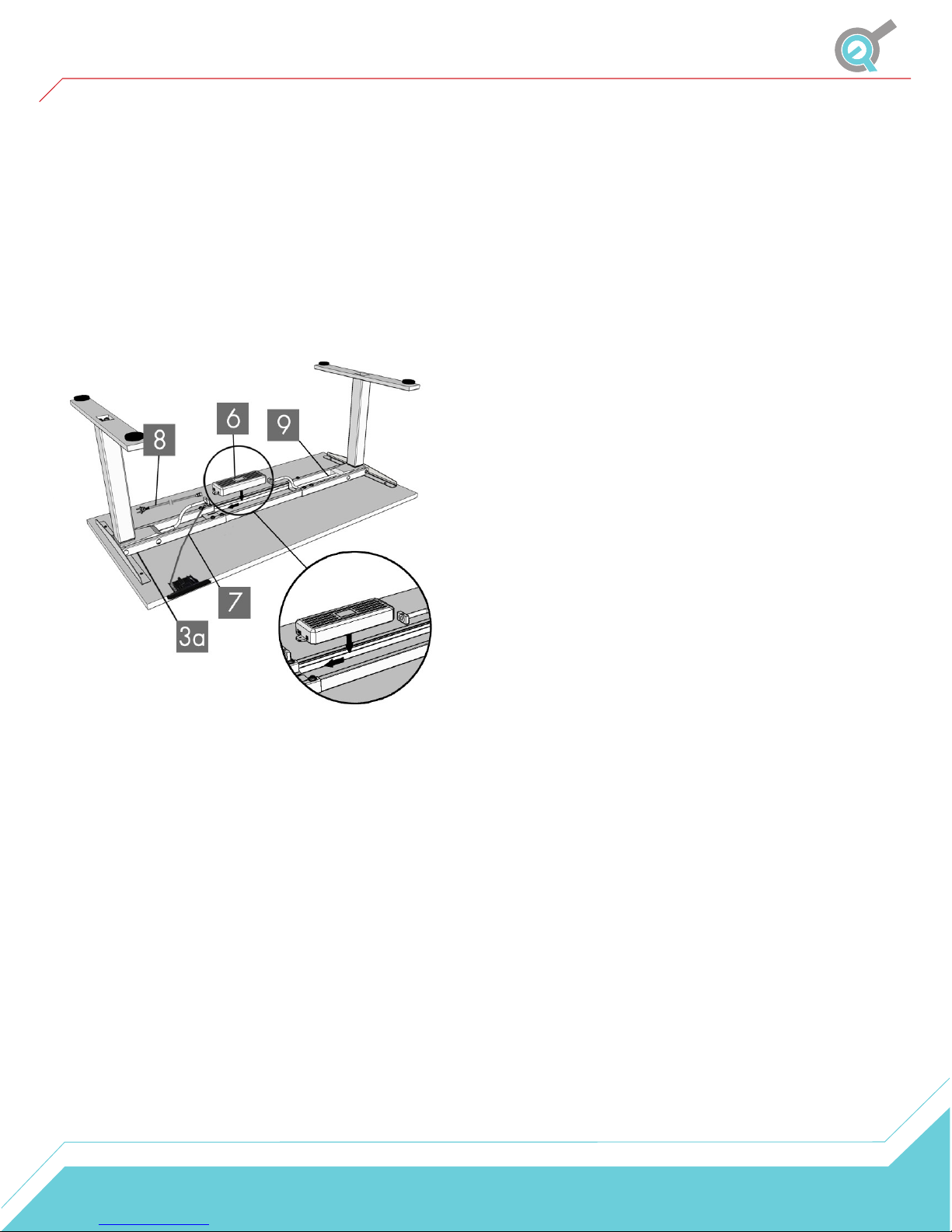
STEP 9
Connect the cable from the Leg (1) that is attached to the
Frame End-CB (3a) directly into the Control Box (6). Then
Slide the Control Box (6) into the Frame End-CB (3a).
Connect the Cable (9) to the other Leg (1) and the
Control Box (6). Then Connect the Hand Remote (7)
cable to the Control Box (6).
Use the adhesive-backed Cable Clips (15) to secure the
cables so they are not loose and in the way.
IMPORTANT
You must reset the desk prior to use:
To reset you must press and hold the DOWN button on
the Hand Remote (7) until the table lift reaches its lowest
point. Release the DOWN button. Press and hold the
DOWN button again until the LED display shows "RST". If
you are not using an LED hand remote hold the DOWN
button for 10 seconds. Release the DOWN button. Finally
press and hold the DOWN button once more until the
desk lowers, slightly rises then stops. Release the DOWN
button and your desk is now ready to use.
To program up to four presets with the remote just use the
Up/Down buttons to find your desired height, then press
the “M” button followed by a number 1-4.
Once a preset button is pressed, the desk will move to the
programmed height. Make sure no obstacles are in the
desk's path or in contact with any walls.
STEP 10
We recommend having two people for this step. Grab the
fully assembled desk by the legs (not by the desktop) and
turn the desk right-side up. Adjust the pre-installed glides
on the Feet (2) as needed.
STEP 11
Plug the Power Cord (8) into a 110V outlet.
7
Page 8
Operational Procedure
Once your table lift is installed, operation is simple. Using the wired remote will allow full control over
extending and retracting the lift columns. Use the up button to raise the table lift and the down button
to lower the table lift.
You can program up to 4 locations using the memory setup: Use the up/down buttons on the remote to
find your desired height(s), then press “M” followed by a number 1-4. The table height position is now
saved. To move to the set position, hold the number button.
Reset Procedure
IMPORTANT
You must reset the desk prior to use:
To reset, press and hold the DOWN button on the Hand Remote (7) until the table lift reaches its
lowest point. Release the DOWN button. Press and hold the DOWN button again until the LED display
shows "RST". If you are not using an LED hand remote hold it for about 10 seconds. Release the
DOWN button. Finally Press and hold the DOWN button once more until the table lift lowers, slightly
rises then stops. This signals the end of the reset procedure. Release the DOWN button and your table
lift is now ready to use.
Troubleshooting
If your desk is not functioning it might need to be reset. Follow the RESET procedure.
If your hand remote has an LED display and it displays "RST" (reset), perform the reset procedure.
If the LED displays shows an error message ("Er1" - "Er13"), confirm that all wired connections are
secure. Then perform the reset procedure.
If the LED remote displays "HOT", let the unit cool down for 20 minutes.
If the error message persists after the reset procedure, contact us at 1-800-676-6123 or
[email protected].
8
Page 9
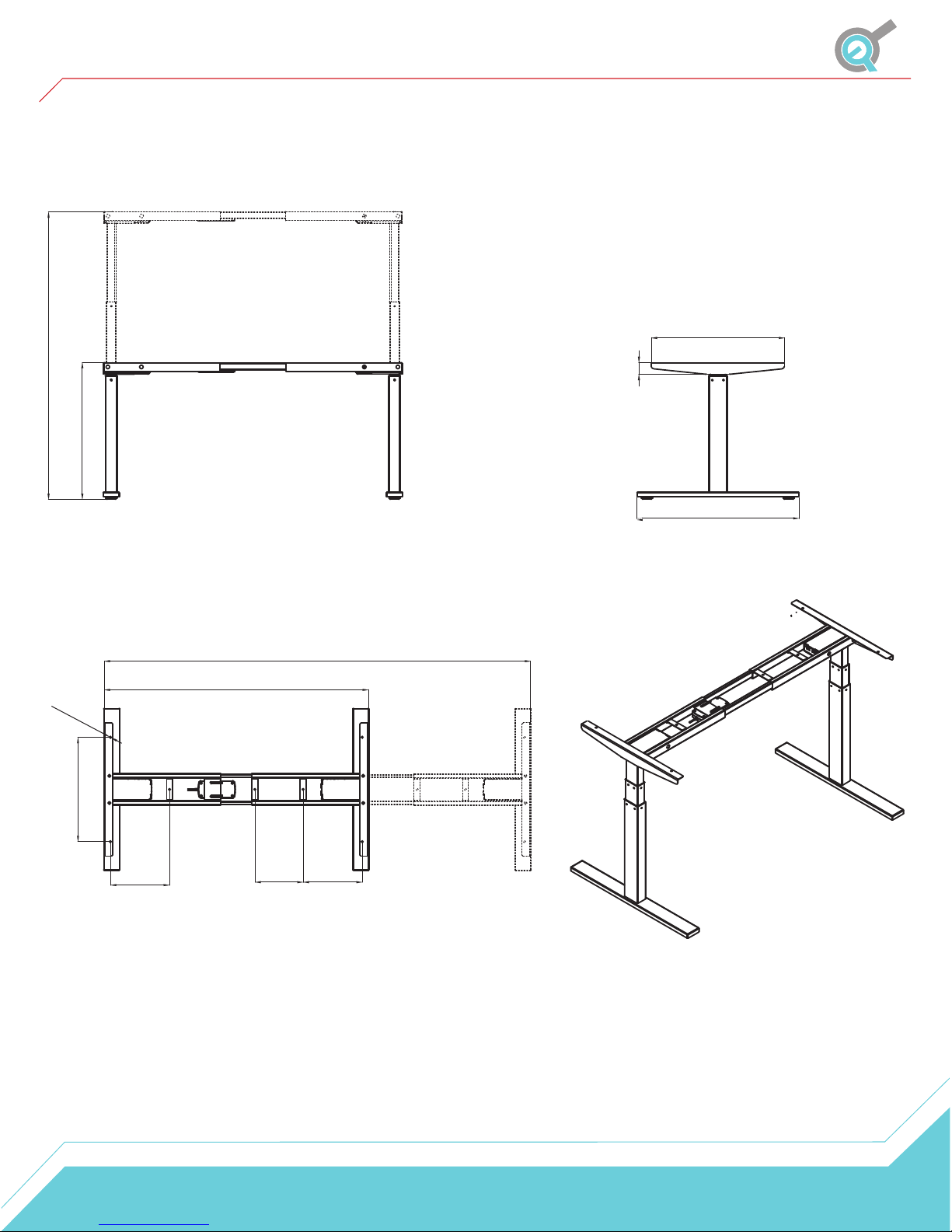
Dimensions
49"
23.5"
22.6"
2"
27.5"
0.3"
17.7"
10"
43"
8.2"
72.4"
10"
9
 Loading...