

Page 1
FLT-01
User Manual
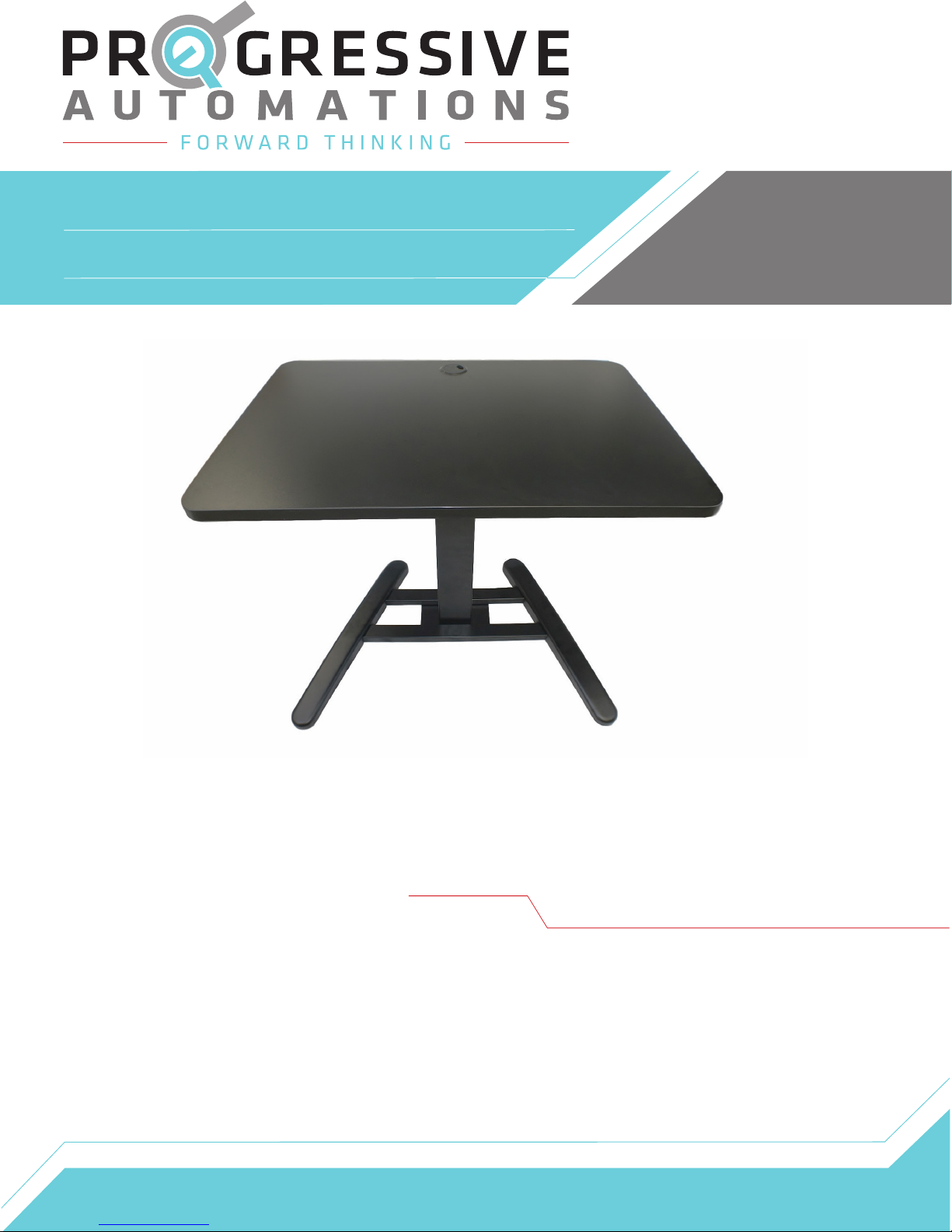
The FLT-01 is a single leg table lift set with an 18.1” stroke size and 175 lbs
of force. This model includes a power supply, remote for an interactive up/
down motion control, and a table top so you have everything you need for
your ideal height adjustable table.
Contents
Caution/Information
Use/Liability
Technical
Specifications
Troubleshooting
Parts
Assembly
Instructions
Page 2
Page 2
Page 3
Page 3
Page 4
Page 5-6
Page 2
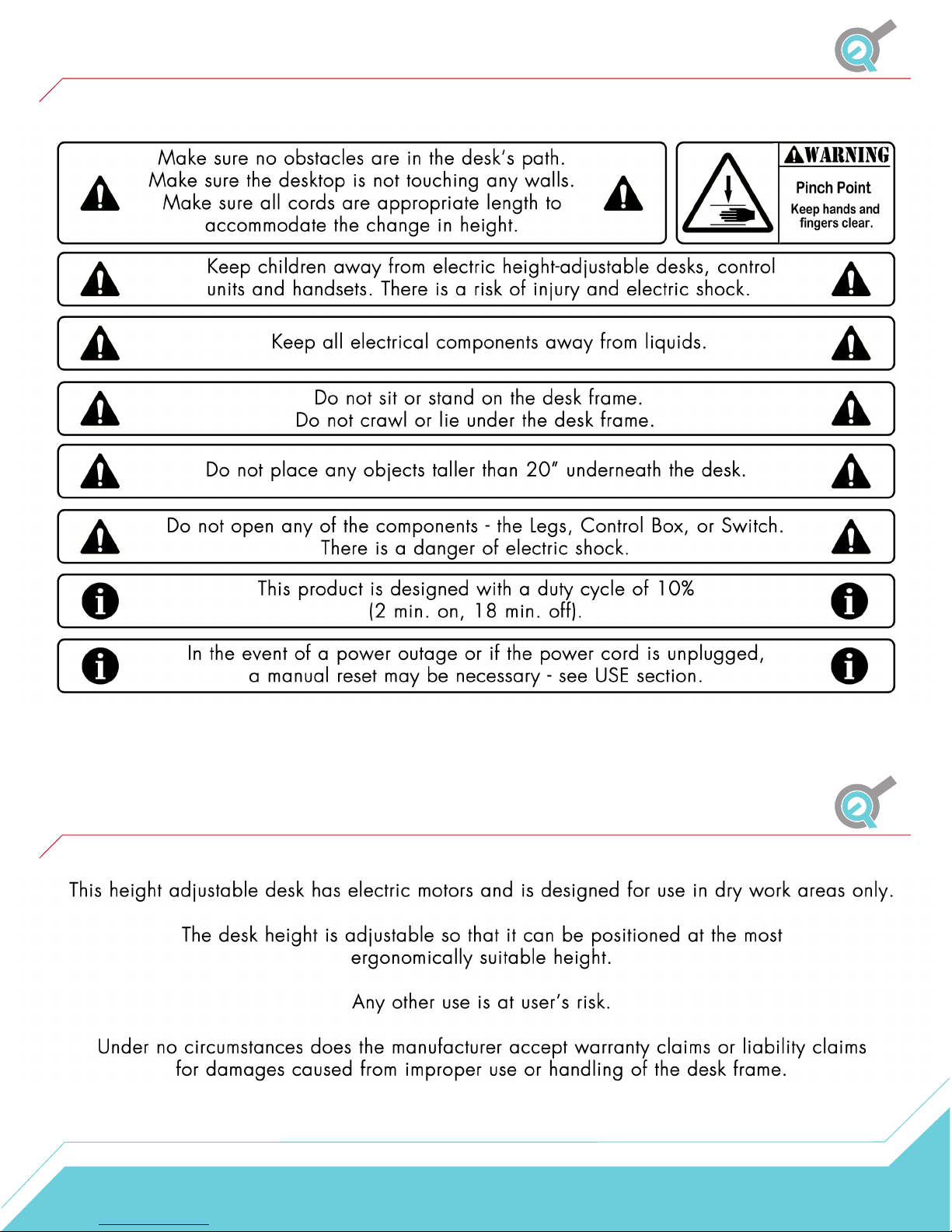
Caution/Information
Use/Liability
2
Page 3

Technical Specifications
Height Range
Base Width
Minimum Table Top Size
Travel Speed
Weight Capacity
Duty Cycle 10% Max. 2 mins on, 18 mins off
Features Soft start/stop
26.6” - 44.7”
43” min. - 72.4” max.
43"x 24”
0.8" per second (varies, slowest w/ max load)
180 lbs.
Adjustable leveling studs
39.5" x 27.5" Table top included
Troubleshooting
If the unit is not functioning correctly for any reason, contact us at 1-800-676-6123
or [email protected].
3
Page 4
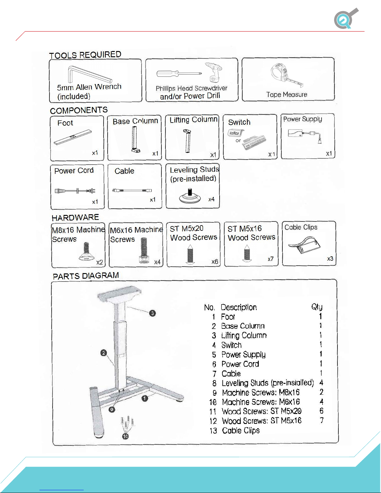
Parts
4
Page 5
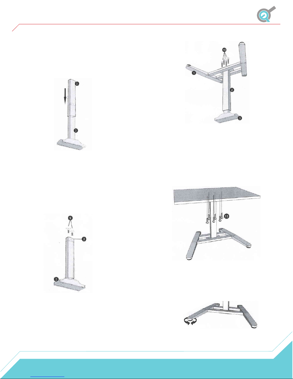
Assembly Instructions
STEP 1
Lay out all the included components and hardware to
ensure you have everything listed on the parts page.
Take the Lifting Column (P3) and place it upside
down. Then slide the Base Column (P2) over the
Lifting Column (P3) until it is fully inserted.
STEP 2
When sliding the Base Column (P2) over the Lifting
Column (P3) make sure to line up the holes in the bottom
of the Base Column (P2) with the holes in the bottom of
the Lifting Column (P3). In order to line up the holes you
may need to adjust the Base Column (P2) a bit until both
holes line up. Secure the Base Column (P2) to the Lifting
Column (P3) with the two M8x16 Machine Screws (P9)
and using the supplied Allen Wrench, tighten the two
screws until secure.
STEP 4
For this step we recommend pre-drilling the included
desktop before attaching it to the Lifting Column (P3).
Turn your assembled desk base right-side up and place
the desktop onto the desk base. Using the six M5x20
Pan Head Wood Screws (P11), secure the desktop to
the desk base. Make sure not to damage the desktop
surface when securing the screws.
STEP 3
For this step we recommend using two people to
be safe. Turn the Foot (P1) upside down and
place the steel plate in the center over the Base
Column (P2). Secure the Foot (P1) to the Base
Column (P2) with the four M6x16 Machine Screws
(P10). Using the supplied Allen Wrench, tighten
the screws until secure.
STEP 5
Adjust the four Leveling Studs in the Foot (P1)
as needed.
5
Page 6
Assembly Instructions
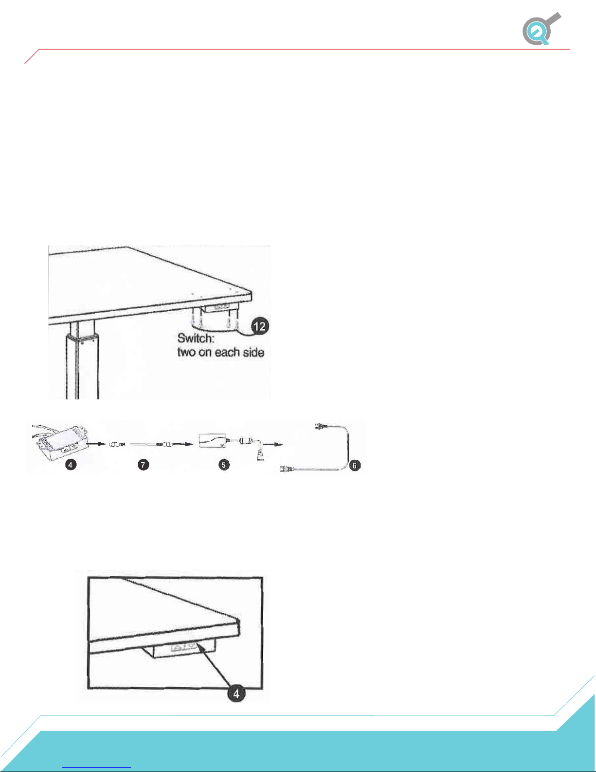
STEP 6
Attach the Remote (P4) to the underside of the
desktop with the four M5x16 Pan Head Wood Screws
(P12). Then connect the Remote (P4) to the Power
Supply (P5) using the Cable (P7). Finally connect the
Power Cord (P6) to the Power Supply (P5).
Use the adhesive-backed Cable Clips (P13) to secure
the wires so they don’t get in the way.
STEP 7
Plug the Power Cord (P6) into a
110V outlet.
6
 Loading...