

Progress Replacement Motion Sensor P6036 Owner's Manual
MANUAL MODE
AUTO
TEST
Replacement
Motion Sensor
Requirements
• The Light Control requires 120-volts AC.
• If you want to use Manual Mode, the control must
be wired through a switch.
• Some codes require installation by a qualified
electrician.
598-1280-00
Features
• Turns on lighting when motion is detected.
• Automatically turns lighting off.
• Photocell keeps the lighting off during daylight
hours.
•
LED indicates motion was sensed (day or night).
Model P6036
OPERATION
* resets to Auto Mode at dawn.
Note: When first turned on wait about 1 1/2 minutes
for the circuitry to calibrate.
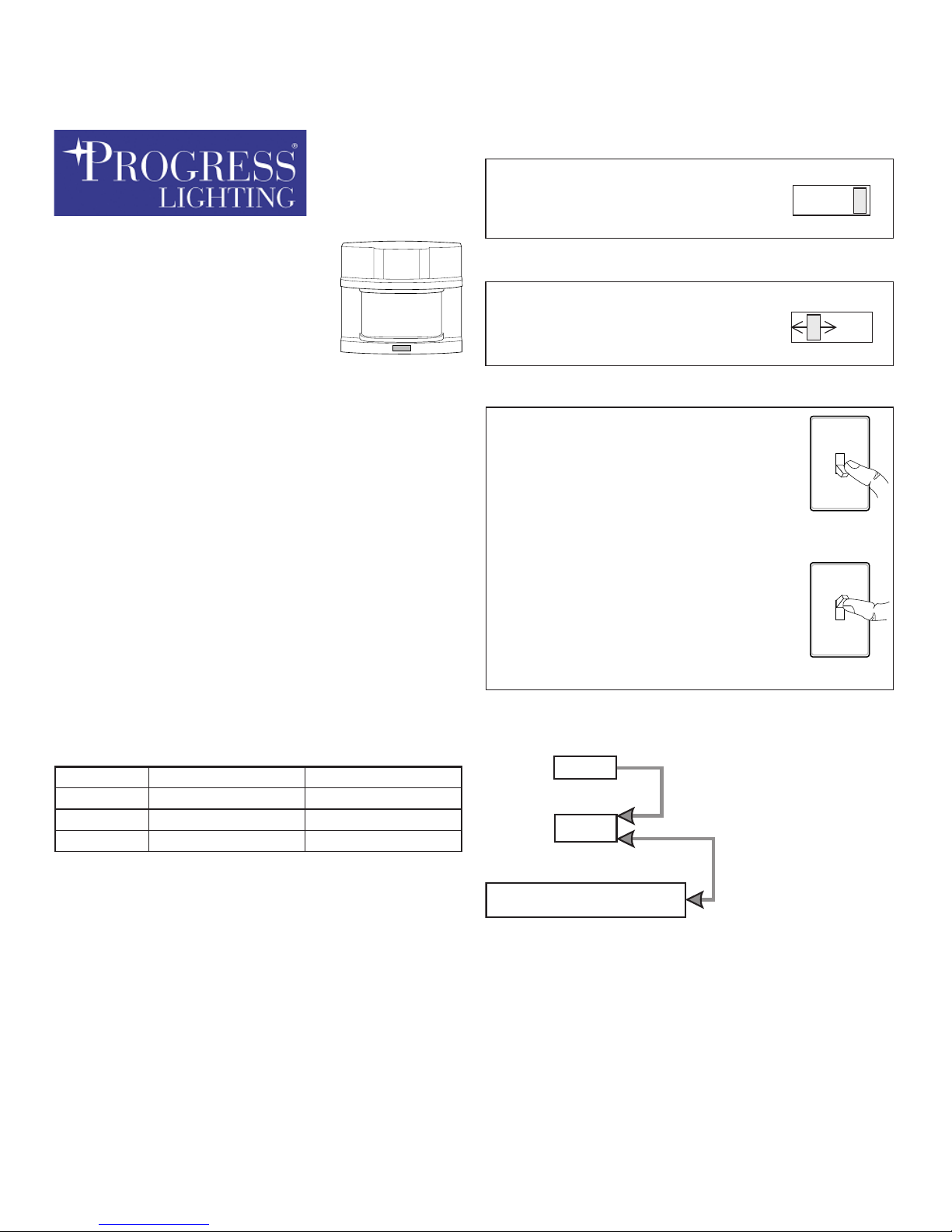
ON-TIME
10 5 1 TEST
10 5 1 TEST
ON-TIME
Put the ON-TIME switch in the 1,
5, or 10 minute position.
Put the ON-TIME switch on the
bottom of the sensor in the TEST
position.
Manual mode only works at night
because daylight returns the sensor to AUTO.
Flip the light switch off for one
second then back on to toggle
between AUTO and MANUAL
MODE.
Manual mode works only with the
ON-TIME switch in the 1, 5, or 10
position.
Move ON-TIME Switch to
1, 5, or 10 minutes
Mode Switching Summary
Flip light switch
off for one second
then back on*
* If you get confused while switching modes, turn
the power off for one minute, then back on. After
the calibration time the control will be in the AUTO
mode.
TEST
AUTO
MANUAL MODE
... back on.
1 Second
OFF
then...
Mode: On-Time Works: Day Night
Test
5 Seconds x x
Auto
1, 5, or 10 Min
x
Manual
To Dawn*
x
-2-
598-1280-00
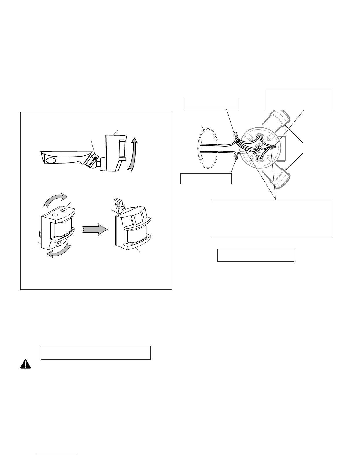
❒ Swing the sensor head towards the clamp
screw.
For eave mount only:
Controls
INSTALLATION
Wire the Light ControL
WARNING: Turn power off at the fuse or
circuit breaker.
❒ Remove the existing light fixture, if present.
These instructions show the sensor wired to flood
lamps. The white sensor wire is neutral. The black
sensor wire is hot. The red wire is the switched
"hot" wire. The lighting load (500 W, 4.2A max) is
placed across the white and red wires.
❒ After screwing the sensor into the wall plate,
connect the junction box wires to the Light
Control wires by twisting together and securing
with wire connectors.
Mount the Light
❒ Follow the instructions that came with your light fix-
ture for mounting and adjusting the light fixture.
❒ Keep regular PAR-38 lamps at least 1" (25 mm)
from the sensor. Halogen lamps should be kept
at least 2" (51 mm) from the sensor.
Black to Black
White to White
Red Sensor Wire to
Black Lamp Wire
Optional: Connect additional load
across the white and red wires. Total
lighting load including lampheads on
fixture must not exceed 500W (4.2A).
Junction
Box
Lamp Holders
For under eave installation, the sensor head
must be rotated as shown in the next two steps
for proper operation and to avoid the risk of electrical shock.
❒ Rotate the sensor head clockwise 180° so
the controls face down.
Clamp Screw
Controls
Controls
If the sensor pops out of the ball joint, loosen the
clamp screw and push the sensor back into the
ball joint. Tighten the clamp screw when done.
 Loading...