

Page 1

1
INSTRUCTION
MANUAL
VERSION 2 AT 220 Vac (or 115 Vac)
INDEX
Section Theme Page
1. INDEX/PRESENTATION 1
2. BASIC FUNCTIONAL DESCRIPTION 2
Sections for the installer
3. DIMENSIONS 5
4. INSTALLATION 5
4.1. Placing the unit 5
4.2. Connection placing 6
4.3. Connection 7
Charts to write down the relay outputs 9
4.4. Extensions 12
4.5. Maintenance 12
4.6. Codification of inputs and outputs 12
4.7. Installer’s configuration 13
5. TECHNICAL CHARACTERISTICS 15
6. PARAMETERS 16
6.1. Fertilization parameters 16
6.2. Filter cleaning parameters 17
6.3. General outputs parameters 18
6.4. Input parameters 19
6.5. Flow parameters 22
6.6. Sectors parameters 22
6.7. Programs parameters 23
6.8. Communication parameters 25
6.9. Miscellaneous parameters 29
PRESENTATION
We wish to take this opportunity to thank you for the confidence in us which you have demonstrated in ex-
pressing interest or acquiring the AGRÓNIC 4000.
This confidence, for our part, stimulates our efforts to meet and surpass the expectations of our clients to jus-
tify the traditional quality of our products.
This manual will explain the specification of the equipment as well as its installation and use.
However, if after reading this you still have any doubts, contact us and we will happily answer them.
Sections for the user
7. PROGRAMS 30
8. READINGS 33
8.1. Totals readings 33
8.2. Anomalies readings 34
8.3. History readings 35
8.4. Sensors readings 36
8.5. Agrónic Radio 868 readings 36
8.6. Agrónic Radio 2,4 readings 36
8.7. Agrónic Monocable readings 36
9. ERASURE 37
10. MANUAL 37
11. CLOCK 38
12. VIEW 39
12.1. General view 39
12.2. Programs view 40
Notes 41
GENERAL SUMMARY 42
Page 2

2
2. BASIC FUNCTIONAL DESCRIPTION
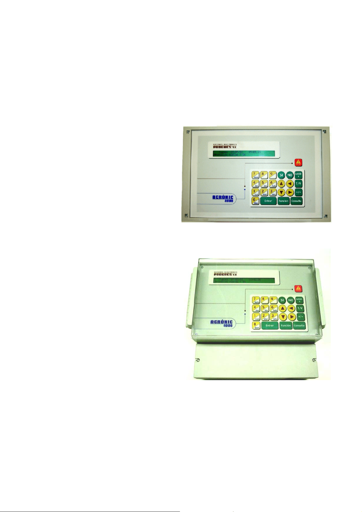
Electronic unit for the control of irrigation, fertilization, pH, pumping and filter cleaning, plus malfunction
detection and with the possibility of telemanaging the
data via PC or mobile phone.
Models with 16, 24, 32, 48, 64, 80 and 96 configurable outputs, plus 12 signal inputs at the base. Extension of configurable outputs and inputs for the
reading of analogical and digital sensors; both by
direct connection to the unit or by means of field
modules via cable 24 Vac or Monocable, or through
the Agrónic Radio system. Possibility of programming
by time and volume, both in irrigation and fertilization
as in filter cleaning, with possibility of mixed
ance (independent for each sub-program).
By means of climatic or crop sensors, it can influence the start conditions or the irrigation and fertilizer
units.
IRRIGATION
It can control up to 99 irrigation sectors, governed by 40 sequential programs, with 12 subprograms in every sequence (total 480), and possibility of linking programs in order to carry out sequences
of 24, 36, or more sub-programs.
Every sub-program can activate from 1 to 10 irrigation sectors simultaneously.
Every program can start its performance at a
concrete time, when another program finishes, when a
sensor reaches a certain value (°C, soil moisture, etc.),
due to an input when a contact is closed, by mobile
telephone via SMS message. It can also start its performance according to the days of the week, the irrigation frequency (irrigate every day, every 2 days, every
3 days, etc.) or irrigate every day with several performances. The period of the year when the program
has to work can also be indicated. In a start by sensors, an active period and a margin of time between
starts can be chosen.
Modification of irrigation and fertilization units by
a manual factor or by sensors which will have an influence depending on their values from the previous
irrigation, such as rain, evapotranspiration, integration
of the solar radiation, etc.
When an irrigation is taking place, a program can
be cancelled temporarily by sensor values such as
wind, temperature, level, etc.
Grouping of programs up to 9 groups so that only
one program of every group can irrigate at the same
time.
Complete control of instantaneous flow of four
possible irrigation counters, with programming of the
expected flow in each sector and tolerance percentage both for excess or lack.
FERTILIZATION
Capacity to configure from 0 to 8 fertilizers, in independent tanks.
perform-
Independent pre- and post-irrigation values for
every program.
The time or volume of application of every fertilizer can be programmed independently for every subprogram.
The use of mixers can be configured, with premixing and intermittent or non-stop mixing.
Fertilizers can be applied in two different ways:
In series: one type of fertilizer after the other,
with just one injector. In proportional fertigation, independent proportions for every fertilizer.
In parallel: several fertilizers are applied simultaneously, with one injector for every one
of them. In proportional fertilization, independent proportions for every type of fertilizer
and sub-program.
The injection track can be cleaned automatically,
with water, between the application of different types
of fertilizer and at the end of the fertilization.
Reading of the instantaneous flow of fertilizers, as
in irrigation.
With the option of “control pH”, it can be controlled by injecting acid or base with a reference value
independent for every sub-program. With values of
alarm by excess or lack in the reading of the pH and in
the electrical conductivity (EC).
It is possible to choose the control of pH at the
pre-irrigation and post-irrigation.
PUMPING
It has from 1 to 4 general irrigation outputs, which
can be assigned to sectors, with independent activation and deactivation temporizations. The general
number 1, by means of the “pressure regulation option”, can give a 0-10 volt Analog output, in order to
connect it to a frequency variator and maintain a pressure in the irrigation pipe line independent for every
sector.
Optional control of a diesel engine, with outputs
for start, stop, contact and warming up. Start and stop
control of the electrical pumps.
FLOWS
Every irrigation sector can be assigned to one of
the 4 possible volumetric counters to irrigate in liters
3
or m
. In the totals, the volume of irrigation and fertilizer is shared in proportion to the nominal flow assigned to every sector.
The fertilizer is programmed in liters, deciliters or
centiliters with 8 counters.
FILTER CLEANING
Up to four groups of independent filters, with the
following values:
The number of filters to be used in every group
can be configured. Two cleaning times for every filter
group. Pause time between filters. The cleaning can
be started by the differential pressure and/or by the
time or volume of water circulation. Start or not of the
Page 3

3
sectors when cleaning. Assignation of generals and
counters. Control of continuous cleanings.
MANUAL CONTROL
With manual control, you can start, stop and
leave out of service irrigation programs; out of service
or general Stop; start or stop the filter cleaning; end of
alarms and malfunctions; direct activation of the outputs.
READINGS
It can have the following records which are always updated:
Sector totals and a general one to show the irrigation units in time and volume plus the calculated
flow and the applied units of every fertilizer.
Anomalies which have taken place during a period of several weeks, such as a power cut, flow cut,
filter cleaning, fertilizer without control, irrigation or
fertilizer counters, too much fertilizer, proportional
fertilization, lack of communication with external modules, due to inputs of general malfunction, definitive,
temporary or conditional stop, intrusion alarm, pH and
EC sensors, error in memory, start and pressure in
diesel engine, etc. All of them go with the day and
time when they took place and the most relevant data
in relation to the type of anomaly.
New anomalies: with this record, the anomalies
that have taken place since the last visualization are
displayed.
Record of the last 30 days, where the starts of
every program, the filter cleanings that have taken
place, the integration of the solar radiation and the
room temperature, the rain accumulated that day and
the evapotranspiration are showed. It will also show,
for every sector, the irrigating units which have been
carried out, the average of EC and pH applied and the
fertilizer units. When there is a connection to a PC, the
average of the readings of every half an hour, of every
one of the 30 days will be recorded from the first 20
sensors, and the readings of all the active life of the
unit can be stored.
Sensors: with the instantaneous value of the different sensors connected to extensions, field modules
or Microisis connected to the Agrónic 4000.
Connecting a personal computer (PC), the operations are recorded, showing the day and time of
every operation carried out by the unit, such as
anomalies, irrigation starts with their main values, performance of the filters, mixers, erasures, etc. The information can be selected by means of the date, programs and anomalies. The Agrónic 4000 has a recording capacity of several weeks.
ALARMS
It can generate alarms for more than 20 different
conditions, activating one of the two alarm outputs
(general and fertilization), recording the anomaly and
sending a warning by GSM message if necessary.
VISUALIZATION
Lightened screen of 2 lines of 40 characters, with
internal contrast adjustment. Membrane keyboard with
23 keys and pulsing acoustic warning device. “STOP”
key.
MANAGEMENT THROUGH A PC
The unit can be managed through a personal
computer by means of a PC program for the Agrónic
4000.
It can be linked via cable (RS232 or RS485) or by
means of a telephonic modem (conventional or GSM).
Punctual information of the controller (recording,
incidences, situation of the irrigation, etc.) can be obtained from the PC, giving the opportunity of acting on
the Agrónic, modifying parameters, programs, ranks,
etc., from any place using the PC.
SMS MESSAGES
Connected to a GSM modem, “SMS messages”
can be sent to a digital telephone, with alarms and
incidences and regular messages of pre-established
values. It can also receive orders such as start or stop
a program, set at “Stop”, modify the manual factor of
a program, give the value of a virtual sensor such as
the evapotranspiration, etc.
The sending of one or two reports a day about
the irrigations that have taken place to a mobile phone
can be configured
EXTERNAL MODULES
Capacity to connect with external modules of dif-
ferent types:
Expansion modules: up to 16 modules with 5 re-
lay outputs, 2 digital inputs and 2 Analog inputs
every one and communication through the 24
Vac line.
Agrónic Radio 868 and 868-16: up to 64 modules,
it is possible up to 16 latch solenoid outputs,
and up to 16 digital inputs, and 2 analog inputs
for sensors for each one of them.
Agrónic Radio 2,4: up to 120 modules, it is possi-
ble up to 16 latch solenoid outputs, and up to
16 digital inputs, and 2 analog inputs for sensors for each one of them.
Agrónic Monocable 64 and 120: up to 120 mod-
ules, it is possible up to 8 latch solenoid outputs, and up to 10 digital inputs and 1 analog
input at every one.
Via Radio 400 MHz: up to 31 modules with 4 or 7
outputs for latch solenoids of 2 wires, solar
panel and battery for every one of them.
4 Microisis with 8 Analog inputs for sensors every
one.
µMetos: reading collection station of 24 different
probes.
MODELS AND OPTIONS
Model to “to built- in” a frame or “box” in a wall.
Page 4
4
Model with power supply at 230 Vac. (115 Vac.)
or at 12Vdc.
Extension of Analog inputs and outputs, 4 inputs and 2 outputs 0-10 V.
Extension at 3 serial ports.
Modem for connection to expansion modules.
Expansion modules for field by cable being able
to collect data about sensors.
Expansion modules for field via radio.
Option of sending GSM messages.
Option of link to PC through a serial port RS232,
RS485 or by means of GSM modem.
Option of regulation of the pressure of the irrigation water.
Option control pH and reading EC with alarm.
Option conditioning of programs by sensors.
Option diesel engine.
Latch outputs (pulses) for two or three wires.
Double voltage at outputs.
Option of link with Agrónic radio.
Option of link Monocable Modules.
Option of link Microisis.
Option of link MicroMetos.
Version in Spanish, French, English, Italian and
Portuguese.
WARRANTY
The irrigation controller Agrónic 4000 meets all the
norms set by the CE.
The products created by PROGRÉS enjoy a two-
year warranty against all manufacturing defects.
Compensation for direct or indirect damage
caused by the use of the equipment is excluded from
the warranty.
Page 5
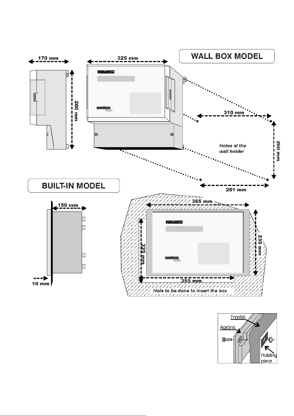
3. DIMENSIONS
5
4. INSTALLATION
4.1. PLACING THE UNIT
Place the unit at the right position and height.
Avoid direct sun exposure, humidity, dust and
vibrations.
Avoid proximity to any source of interference
which could affect the correct operation of the unit.
The A-4000 is made up of just one piece, except
the built-in models with more than 32 outputs, which
go with a second box.
In the “built-in model”, a hole is to be
done in the frontal part
of the wall or desk,
according to the measures in the section
DIMENSIONS. It will be
held with the screws of
the corners, using the
four pieces which are included in the unit.
The wardrobe must have a double isolation with
protection for the operation relationship to the net
power supply circuit.
Page 6
6
In the “box” model, the unit is held by the upper
pieces at the corners and by the two holes placed at
the below cover of the connection housing, according
to the measures shown in the section DIMENSIONS.
In the version with "box", the equipment is
provided in a hermetically sealed (box IP65) with a
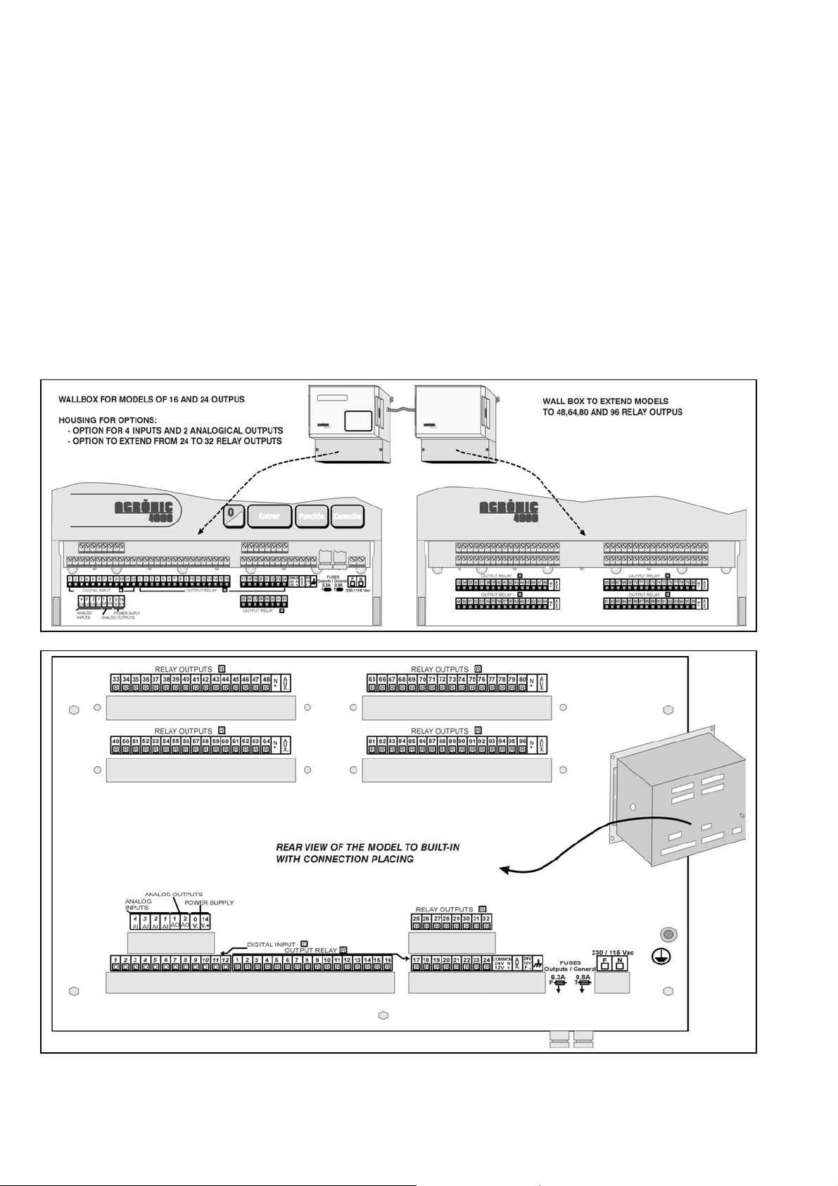
4.2. CONNECTION PLACING
In order to carry out the connections in the unit of
the “built-in” model, access the connectors placed at
the back.
In the “box” model, take the below cover off to
access the connectors.
The necessary terminals have to be taken out to
enter
the cables (do it with the connection cover on
transparent front cover for the keyboard/display and
an opaque cover for the connection housing.
In order to maintain isolation of the box it is
necessary to maintain the covers always closed, as
well as install grommets at the outputs of the cables.
and screwed, in order to avoid possible malfunctions.).
It is advisable to link the cables to the terminals
with connection terminals, which are supplied with the
unit. (The terminals accept cables of up to 2.5 mm
section).
2
of
Page 7
7
4.3. CONNECTION
The unit has to be installed following the
prevailing regulations for electrical installations. The
unit will not be completely protected if it is not used
according to the information given in the manual.
The unit has to be placed in such a way that the
elements which may get interferences, such as the
sensor inputs, the sensor power supply, the links to
the PC and modem, have their cables in the best
emplacement, so that they do not receive
interferences from power elements which might be in
their surroundings.
All the connection terminals of the Agrónic 4000
can be switched which allows a fast maintenance.
Progrés also offers a protection box for all the
terminals, in case there is a high risk of electrical
sparks from storms entering the cables.
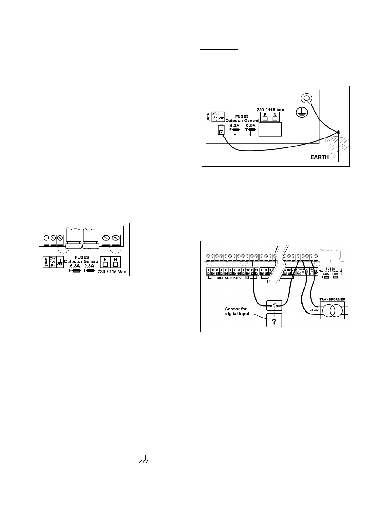
4.3.1. Power connection
Before connecting the unit, it is necessary to
check its identification label where the characteristics
of the power supply are to be found.
The standard power supply is at 230 Vac, being
possible at 115
Vac. but it is
necessary to ask
Progrés about this
last one.
Connect the
phase and the
power supply
neutral to the terminals marked as “N” and “F”.
A 6 amp magneto-thermal switch is to be
included in the installation. It will be used as a
disconnection device and it has to be placed near the
unit at an accessible place for the user.
It is recommendable to do this as directly as
possible, avoiding that the same cable supplies other
devices. Use cable of the H05VV-F type, 1mm
The power supply input is protected by a fuse,
marked as General Fuse
and a varistor.
The varistor might short-circuit the fuse
automatically, on detecting an overload on the line
(lightning, etc.). Replace it with one of the same
characteristics.
For unstable or fluctuating voltages use grid
stabilizers.
4.3.2. Earth terminal connection
The “built-in” model has a terminal screw to
connect the protection earth terminal (in the “box”
model it is not necessary as it has not got a metallic
casing). A pressed terminal will be applied to the
cable when joining it to the screw.
The box terminal marked as is internally
connected to the filters and protections.
Both the earth and the box terminals are used to
screen the circuitry, for this reason, it is very important
2
.
that the earth line is correctly installed and free of
electric noise. It is also used to protect the unit by
directing all electrical sparks through the internal gas
discharger to the earth. These sparks can come in
through the output cables when lightning strikes
during a storm.
4.3.3. Digital input connection
The different elements of the installation, such as
pressure gauges, levels, counters, etc. are to be connected to the group of 12 terminals labeled as “Digital
inputs (D)”. This is done by connecting one contact
pole to the corresponding input and the other pole to
the 24 Vac “COMMON”.
Contacts must normally be open and free of voltage.
One of the 44 possible functions can be assigned
to everyone of the inputs in the section “ParametersInputs”.
The inputs are optically isolated from the internal
circuitry and depend on the same 24 Vac power
supply of the outputs.
4.3.4. Output connection
All outputs are ready to work at 24 Vac (it is very
important not to supply the unit with voltages above to
30V).
The unit must have a external transformer with 24
Vac output and double isolation according to the UNE
EN61010 norm. Its input will be connected to the output of the magneto-thermal switch which protects the
Agrónic 4000. The 24Vac output is connected to the
terminals marked with this voltage, entering a pole of
Page 8
8
the output of the transformer into one of the terminals
marked as “COMMON / 24 V N”, and the other pole
into one of the terminals marked as “24 V F”.
Connect the solenoids, relays, etc. between the
output common “COMMON” and the corresponding
output.
Do not exceed the maximum power by output of
1 Amp and the general of 6,3 Amp. If this happens
insert external relays.
The “output fuse” protects from overloads and
short-circuits; to replace it half turn the cover of the
fuses box and replace it by another one of similar
characteristics.
The “AUX” terminal corresponds to the “PHASE”
of the 24 Vac which goes through the fuse. It will be
useful to connect auxiliary elements of manual command and extensions of relays above to 32 outputs.
The outputs are isolated from the internal circuitry
by relays and protected by a varistor at everyone of
them, plus a general gas discharger in the lines of 24
Vac.
The number of outputs can vary from 16 to 24,
32, 48, 64, 80 or 96 in the same unit. It is possible to
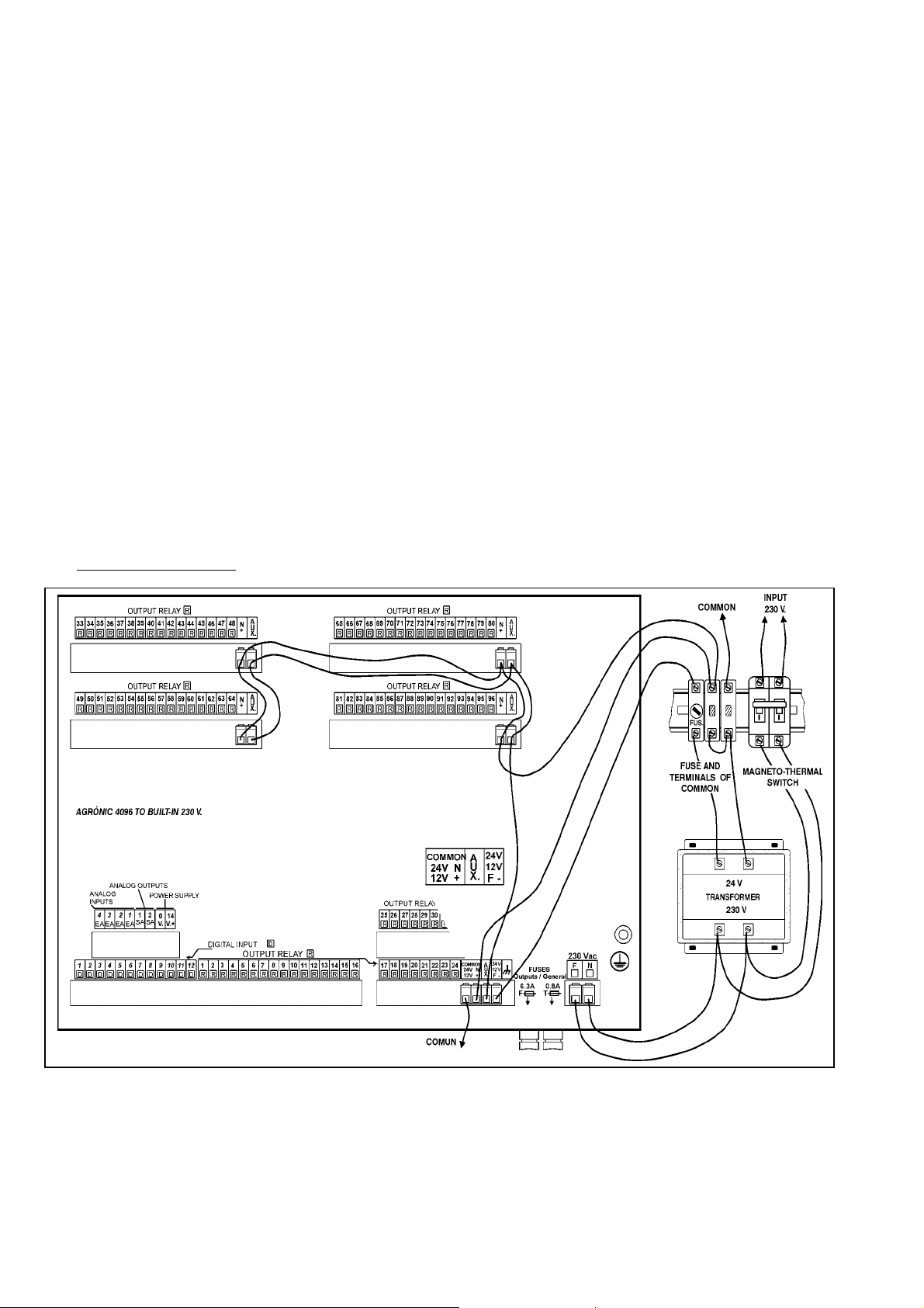
Example of connection
extend the outputs at a distance, in external modules
“via radio” or “via cable”.
The maximum number of sectors to be controlled
by the Agrónic 4000 is 99.
Every output can be assigned to an irrigation sector (one or more electrovalves) or to a general output
(pumps, filters, mixers, etc.). To do so, go to the section of “Parameters-Sectors” or “ParametersGenerals”.
4.3.5. RS232 and RS485 connection links
An Agrónic 4000 with RS232 option will have a
side connector where the power cable may be linked
to a PC and an adapter for connection to modem.
An Agrónic 4000 with RS485 link will have a side
connector (box model) or on the top (built-in model).
This link is always made with bifilar wire: wires A and
B. The connection shall be made by inserting wire “A”
in terminal “1” of the connector and wire “B” in terminal “2”. To connect different equipment through RS485 communication a linear bus must be used, with a
single start and end; it must not be in star topology.
Page 9
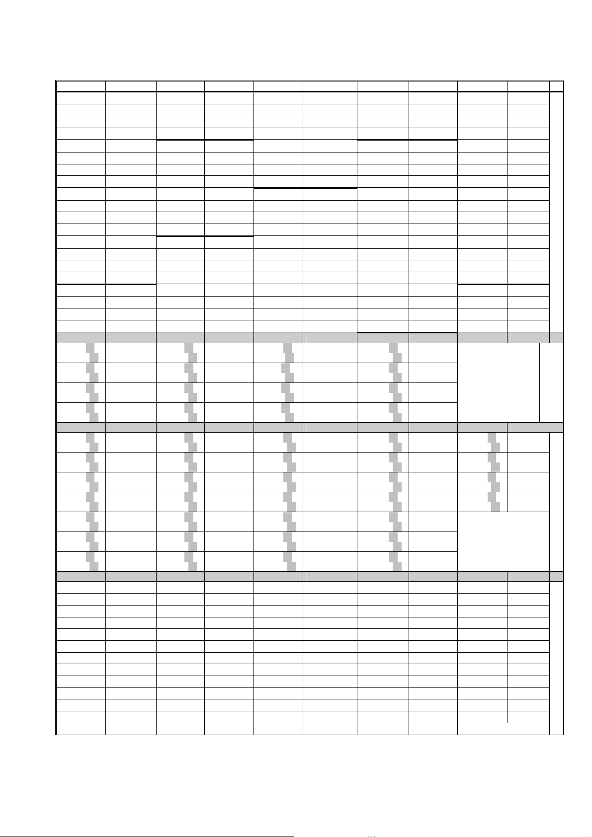
Charts to write down the relay outputs to generals and sectors:
Relay Relay Relay Relay Relay
00000001 00000021 00000041 00000061 00000081
00000002 00000022 00000042 00000062 00000082
00000003 00000023 00000043 00000063 00000083
00000004 00000024 00000044 00000064 00000084
00000005 00000025 00000045 00000065 00000085
00000006 00000026 00000046 00000066 00000086
00000007 00000027 00000047 00000067 00000087
00000008 00000028 00000048 00000068 00000088
00000009 00000029 00000049 00000069 00000089
00000010 00000030 00000050 00000070 00000090
00000011 00000031 00000051 00000071 00000091
00000012 00000032 00000052 00000072 00000092
00000013 00000033 00000053 00000073 00000093
00000014 00000034 00000054 00000074 00000094
00000015 00000035 00000055 00000075 00000095
00000016 00000036 00000056 00000076 00000096
00000017 00000037 00000057 00000077
00000018 00000038 00000058 00000078
00000019 00000039 00000059 00000079
00000020 00000040 00000060 00000080
01000101→
01000105
01000201→
01000205
01000301→
01000305
01000401→
01000405
02100101→
02100108
02100201→
02100208
02100301→
02100308
02100401→
02100408
02100501→
02100508
02100601→
02100608
02100701→
02100708
03100101 03101401 03102701 03104001 03105301
03100201 03101501 03102801 03104101 03105401
03100301 03101601 03102901 03104201 03105501
03100401 03101701 03103001 03104301 03105601
03100501 03101801 03103101 03104401 03105701
03100601 03101901 03103201 03104501 03105801
03100701 03102001 03103301 03104601 03105901
03100801 03102101 03103401 03104701 03106001
03100901 03102201 03103501 03104801 03106101
03101001 03102301 03103601 03104901 03106201
03101101 03102401 03103701 03105001 03106301
03101201 03102501 03103801 03105101 03106401
03101301 03102601 03103901 03105201
01000501→
01000505
01000601→
01000605
01000701→
01000705
01000801→
01000805
02100801→
02100808
02100901→
02100908
02101001→
02101008
02101101→
02101108
02101201→
02101208
02101301→
02101308
02101401→
02101408
01000901→
01000905
01001001→
01001005
01001101→
01001105
01001201→
01001205
02101501→
02101508
02101601→
02101608
02101701→
02101708
02101801→
02101808
02101901→
02101908
02102001→
02102008
02102101→
02102108
01001301→
01001305
01001401→
01001405
01001501→
01001505
01001601→
01001605
02102201→
02102208
02102301→
02102308
02102401→
02102408
02102501→
02102508
02102601→
02102608
02102701→
02102708
02102801→
02102808
02102901→
02102908
02103001→
02103008
02103101→
02103108
02103201→
02103208
9
Base and extensions
modules
Expansion
Agrónic Radio 868 modules
Monocable 64 modules
Page 10
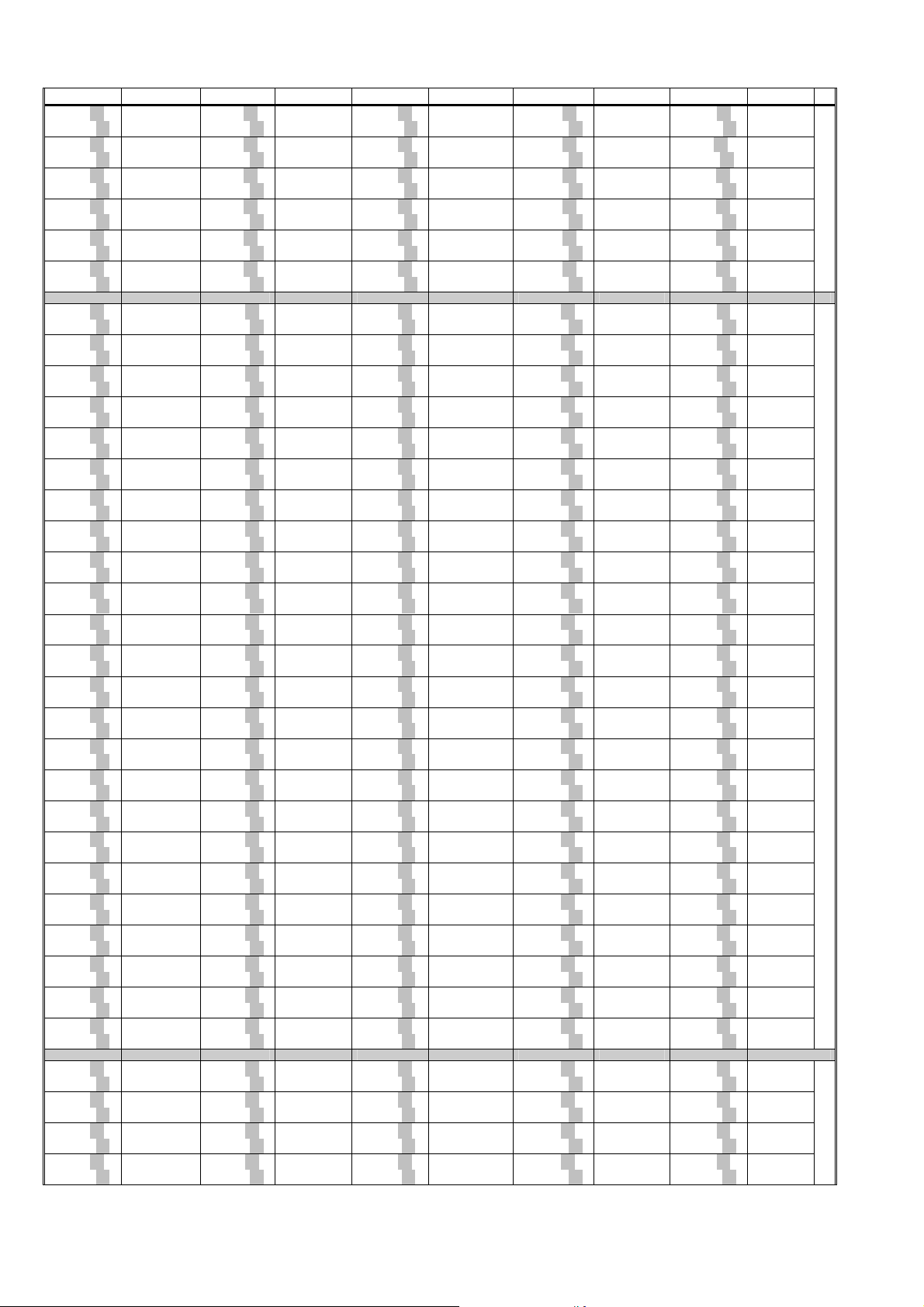
10
A
ó
i
R
di
16 modules
Relay Relay Relay Relay Relay
06000101→
06000115
06000201→
06000215
06000301→
06000315
06000401→
06000415
06000501→
06000515
06000601→
06000615
07100101→
07100108
07100201→
07100208
07100301→
07100308
07100401→
07100408
07100501→
07100508
07100601→
07100608
07100701→
07100708
07100801→
07100808
07100901→
07100908
07101001→
07101008
07101101→
07101108
07101201→
07101208
07101301→
07101308
07101401→
07101408
07101501→
07101508
07101601→
07101608
07101701→
07101708
07101801→
07101808
07101901→
07101908
07102001→
07102008
07102101→
07102108
07102201→
07102208
07102301→
07102308
07102401→
07102408
08100101→
08100116
08100201→
08100216
08100301→
08100316
08100401→
08100416
06000701→
06000715
06000801→
06000815
06000901→
06000915
06001001→
06001015
06001101→
06001115
06001201→
06001215
07102501→
07102508
07102601→
07102608
07102701→
07102708
07102801→
07102808
07102901→
07102908
07103001→
07103008
07103101→
07103108
07103201→
07103208
07103301→
07103308
07103401→
07103408
07103501→
07103508
07103601→
07103608
07103701→
07103708
07103801→
07103808
07103901→
07103908
07104001→
07104008
07104101→
07104108
07104201→
07104208
07104301→
07104308
07104401→
07104408
07104501→
07104508
07104601→
07104608
07104701→
07104708
07104801→
07104808
08101401→
08101416
08101501→
08101516
08101601→
08101616
08101701→
08101716
06001301→
06001315
06001401→
06001415
06001501→
06001515
06001601→
06001615
06001701→
06001715
06001801→
06001815
07104901→
07104908
07105001→
07105008
07105101→
07105108
07105201→
07105208
07105301→
07105308
07105401→
07105408
07105501→
07105508
07105601→
07105608
07105701→
07105708
07105801→
07105808
07105901→
07105908
07106001→
07106008
07106101→
07106108
07106201→
07106208
07106301→
07106308
07106401→
07106408
07106501→
07106508
07106601→
07106608
07106701→
07106708
07106801→
07106808
07106901→
07106908
07107001→
07107008
07107101→
07107108
07107201→
07107208
08102701→
08102716
08102801→
08102816
08102901→
08102916
08103001→
08103016
06001901→
06001915
06002001→
06002015
06002101→
06002115
06002201→
06002215
06002301→
06002315
06002401→
06002415
07107301→
07107308
07107401→
07107408
07107501→
07107508
07107601→
07107608
07107701→
07107708
07107801→
07107808
07107901→
07107908
07108001→
07108008
07108101→
07108108
07108201→
07108208
07108301→
07108308
07108401→
07108408
07108501→
07108508
07108601→
07108608
07108701→
07108708
07108801→
07108808
07108901→
07108908
07109001→
07109008
07109101→
07109108
07109201→
07109208
07109301→
07109308
07109401→
07109408
07109501→
07109508
07109601→
07109608
08104001→
08104016
08104101→
08104116
08104201→
08104216
08104301→
08104316
06002501→
06002515
06002601→
06002615
06002701→
06002715
06002801→
06002815
06002901→
06002915
06003001→
06003015
07109701→
07109708
07109801→
07109808
07109901→
07109908
07110001→
07110008
07110101→
07110108
07110201→
07110208
07110301→
07110308
07110401→
07110408
07110501→
07110508
07110601→
07110608
07110701→
07110708
07110801→
07110808
07110901→
07110908
07111001→
07111008
07111101→
07111108
07111201→
07111208
07111301→
07111308
07111401→
07111408
07111501→
07111508
07111601→
07111608
07111701→
07111708
07111801→
07111808
07111901→
07111908
07112001→
07112008
08105301→
08105316
08105401→
08105416
08105501→
08105516
08105601→
08105616
Radio modules (400MHz)
Agrónic Monocable 120 modules
868o
a
c
n
gr
Page 11
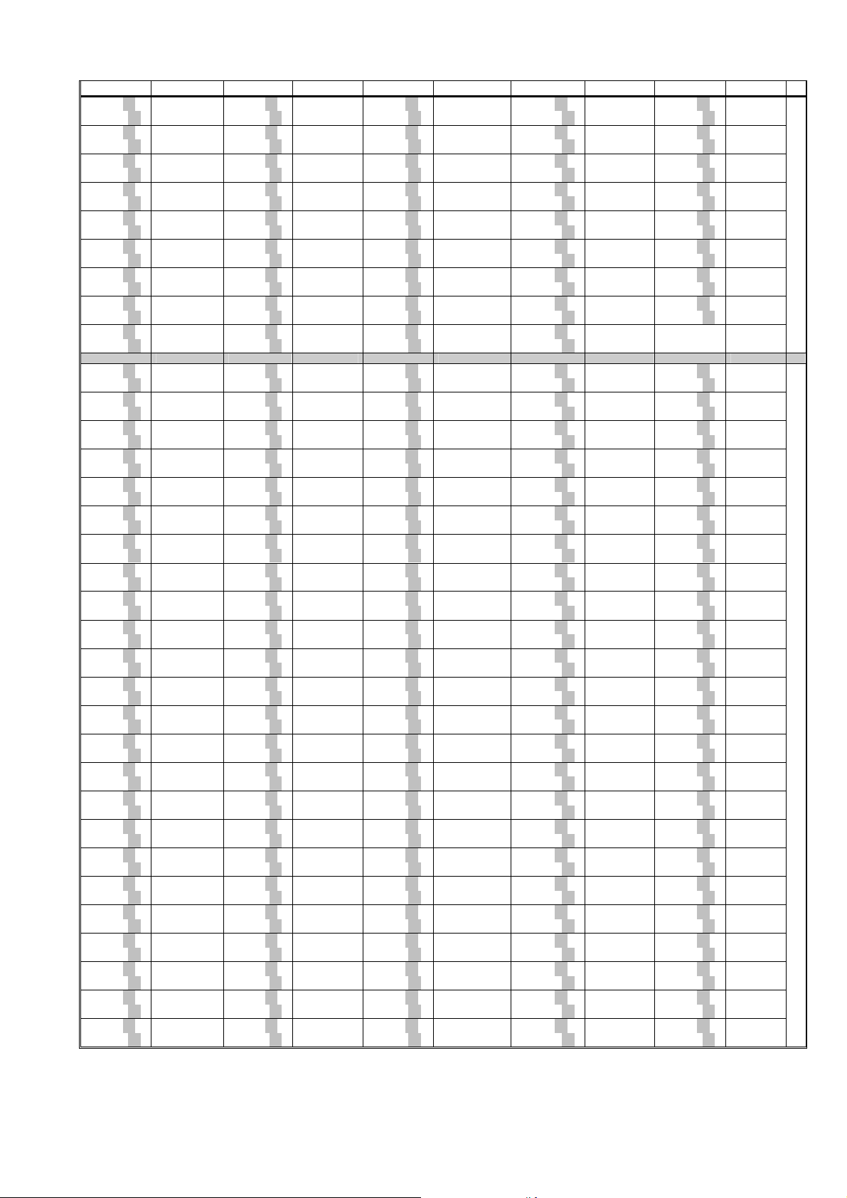
Relay Relay Relay Relay Relay
08100501→
08100516
08100601→
08100616
08100701→
08100716
08100801→
08100816
08100901→
08100916
08101001→
08101016
08101101→
08101116
08101201→
08101216
08101301→
08101316
09100101→
09100116
09100201→
09100216
09100301→
09100316
09100401→
09100416
09100501→
09100516
09100601→
09100616
09100701→
09100716
09100801→
09100816
09100901→
09100916
09101001→
09101016
09101101→
09101116
09101201→
09101216
09101301→
09101316
09101401→
09101416
09101501→
09101516
09101601→
09101616
09101701→
09101716
09101801→
09101816
09101901→
09101916
09102001→
09102016
09102101→
09102116
09102201→
09102216
09102301→
09102316
09102401→
09102416
08101801→
08101816
08101901→
08101916
08102001→
08102016
08102101→
08102116
08102201→
08102216
08102301→
08102316
08102401→
08102416
08102501→
08102516
08102601→
08102616
09102501→
09102516
09102601→
09102616
09102701→
09102716
09102801→
09102816
09102901→
09102916
09103001→
09103016
09103101→
09103116
09103201→
09103216
09103301→
09103316
09103401→
09103416
09103501→
09103516
09103601→
09103616
09103701→
09103716
09103801→
09103816
09103901→
09103916
09104001→
09104016
09104101→
09104116
09104201→
09104216
09104301→
09104316
09104401→
09104416
09104501→
09104516
09104601→
09104616
09104701→
09104716
09104801→
09104816
08103101→
08103116
08103201→
08103216
08103301→
08103316
08103401→
08103416
08103501→
08103516
08103601→
08103616
08103701→
08103716
08103801→
08103816
08103901→
08103916
09104901→
09104916
09105001→
09105016
09105101→
09105116
09105201→
09105216
09105301→
09105316
09105401→
09105416
09105501→
09105516
09105601→
09105616
09105701→
09105716
09105801→
09105816
09105901→
09105916
09106001→
09106016
09106101→
09106116
09106201→
09106216
09106301→
09106316
09106401→
09106416
09106501→
09106516
09106601→
09106616
09106701→
09106716
09106801→
09106816
09106901→
09106916
09107001→
09107016
09107101→
09107116
09107201→
09107216
08104401→
08104416
08104501→
08104516
08104601→
08104616
08104701→
08104716
08104801→
08104816
08104901→
08104916
08105001→
08105016
08105101→
08105116
08105201→
08105216
09107301→
09107316
09107401→
09107416
09107501→
09107516
09107601→
09107616
09107701→
09107716
09107801→
09107816
09107901→
09107916
09108001→
09108016
09108101→
09108116
09108201→
09108216
09108301→
09108316
09108401→
09108416
09108501→
09108516
09108601→
09108616
09108701→
09108716
09108801→
09108816
09108901→
09108916
09109001→
09109016
09109101→
09109116
09109201→
09109216
09109301→
09109316
09109401→
09109416
09109501→
09109516
09109601→
09109616
08105701→
08105716
08105801→
08105816
08105901→
08105916
08106001→
08106016
08106101→
08106116
08106201→
08106216
08106301→
08106316
08106401→
08106416
09109701→
09109716
09109801→
09109816
09109901→
09109916
09110001→
09110016
09110101→
09110116
09110201→
09110216
09110301→
09110316
09110401→
09110416
09110501→
09110516
09110601→
09110616
09110701→
09110716
09110801→
09110816
09110901→
09110916
09111001→
09111016
09111101→
09111116
09111201→
09111216
09111301→
09111316
09111401→
09111416
09111501→
09111516
09111601→
09111616
09111701→
09111716
09111801→
09111816
09111901→
09111916
09112001→
09112016
11
(continuation)
Agrónic Radio 868-16 modules
Agrónic Radio 2,4 modules
Page 12
12
4.4. EXTENSIONS
On installing extensions in the Agrónic 4000, protecting measures have to be taken in order not to
damage the circuits. It is very important to disconnect
any connection to the mains to avoid electro-shock.
Follow the installation instructions enclosed in the
extension element.
characteristics as it may damage the unit if this is not
taken into account.
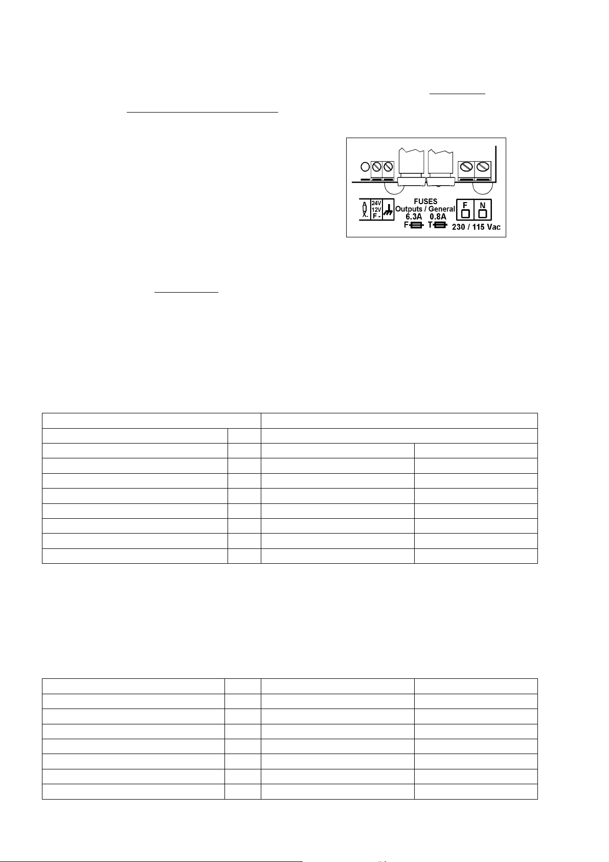
The fuse marked as “Output fuse
outputs from short-circuits. Replace it with one with
the same characteristics as it may damage the unit if
this is not taken into account.
4.5. MAINTENANCE
4.5.1. Fuses
In order to replace the fuses it is necessary, for
precaution, to disconnect the unit from the general
mains, half turn the cover of the fuse holder and insert
one of the same characteristics, as it is indicated at
the label placed next to the fuse holder. Spare fuses
are included in the unit.
The fuse marked as “General fuse”
protects the
power supply input. Replace it with one of the same
4.5.2. Cleaning
The frontal part is cleaned with a slightly humid
cloth, disconnecting the unit from the mains previously.
4.6. CODIFICATION OF INPUTS AND OUTPUTS
Both the analog and digital inputs as well as the digital outputs (relays) are coded using an 8-digit number
that indicates its physical location. Following tables are shown to help code them.
4.6.1. Digital outputs (relays)
Device
00: Base 0 00001 a 00096
Module Output
01: Expansion modules 0 001 to 016 01 to 05
02: Agrónic Radio 868 module 1 001 to 032 01 to 08
03: Agrónic Monocable 64 modules 1 001 to 064 01
06: Via radio a 400MHz modules 0 001 to 030 01 to 15
07: Agrónic Monocable 120 modules 1 001 to 120 01 to 08
08: Agrónic Radio 868-16 modules 1 001 to 064 01 to 16
09: Agrónic Radio 2,4 modules 1 001 to 120 01 to 16
Examples:
00000001: output 1 of the Base
01000103: output 3 of the Expansion module 1 (ME1)
08100503: output 3 of the Agrónic Radio 868-16, Agrónic Radio module 5 (MAR5)
09102301: output 1 of the Agrónic Radio 2,4, Agrónic Radio module 23 (MAR023)
07101005: output 5 of the Agrónic Monocable 120, Agrónic Monocable module 10 (MAM10)
4.6.2. Digital inputs
Device
00: Base 0 000 01 to 12
01: Expansion modules 0 001 to 016 01 to 02
02: Agrónic Radio 868 modules 1 001 to 032 01 to 08
03: Agrónic Monocable 64 modules 1 001 to 064 01
07: Agrónic Monocable 120 modules 1 001 to 120 01 to 10
08: Agrónic Radio 868-16 modules 1 001 to 064 01 to 16
09: Agrónic Radio 2,4 modules 1 001 to 120 01 to 16
Module Input
Output
” protects the
Page 13
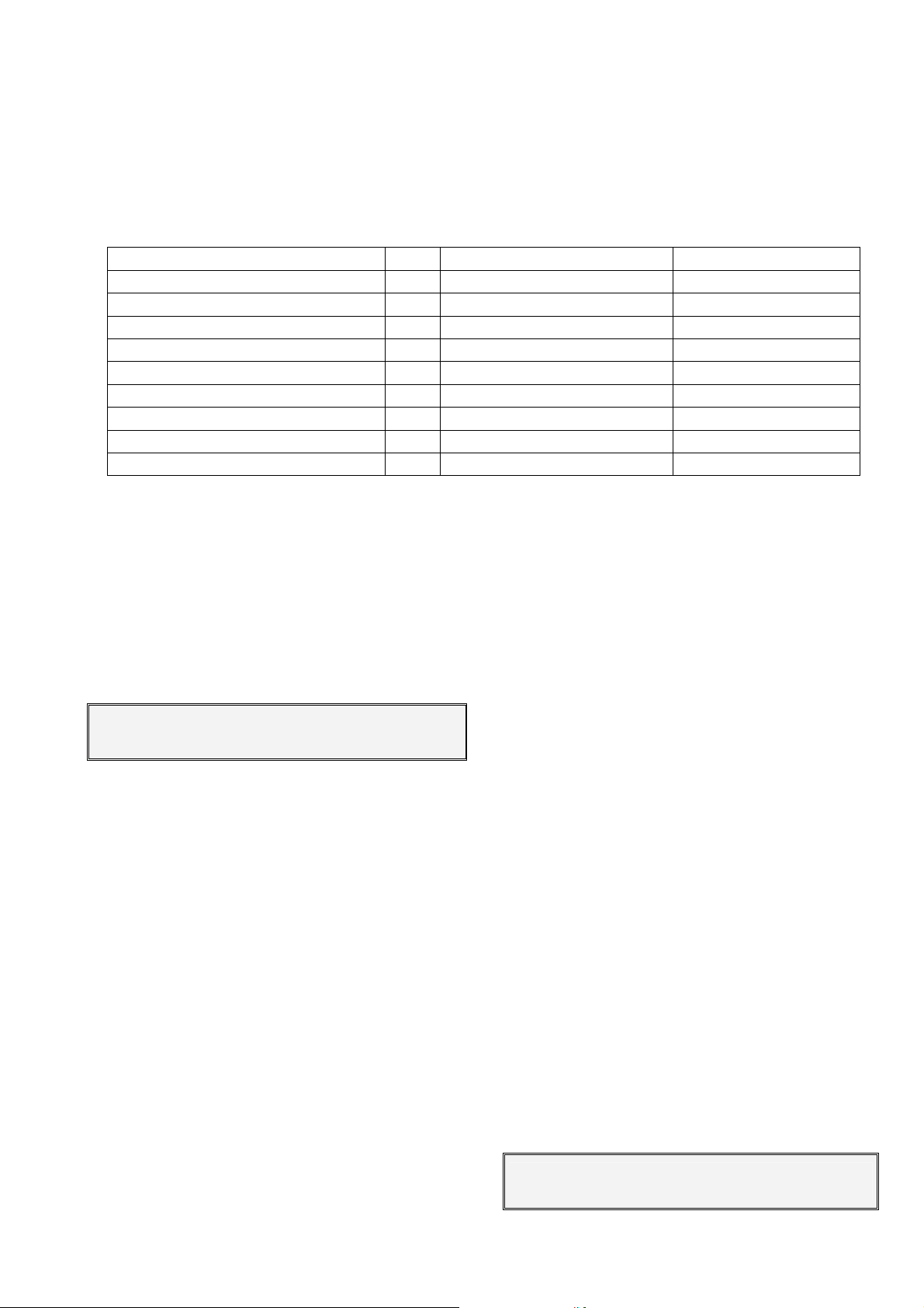
Examples:
00000008: digital input 8 of the Base
01000402: digital input 2 of the Expansion module 4 (ME4)
08101502: digital input 2 of the Agrónic Radio 868-16, Agrónic Radio module 15 (MAR15)
09102301: digital input 1 of the Agrónic Radio 2.4, Agrónic Radio module 23 (MAR023)
07109007: digital input 7 of the Agrónic Monocable 120, Agrónic Monocable module 90 (MAM90)
4.6.3. Analog inputs (sensors)
Device
00: Base 0 000 01 to 04
01: Expansion modules 0 001 to 016 01 to 02
02: Agrónic Radio 868 modules 1 001 to 032 01 to 02
04: SMS Messages 0 000 01 to 08
05: MicroIsis 0 001 to 004 01 to 08
06: Metos 0 000 01 to 24
07: Agrónic Monocable 120 modules 1 001 to 120 01
08: Agrónic Radio 868-16 modules 1 001 to 064 01 to 02
09: Agrónic Radio 2,4 modules 1 001 to 120 01 to 02
Examples:
00000003: analog input 3 of the Base
01001601: analog input 1 of the Expansion module 16 (ME16)
04000003: input of SMS message 3
05000203: analog input 3 of the MicroIsis 2
07101001: analog input 1 of the Agrónic Monocable 120, Monocable module 10 (MAM10)
4.7. INSTALLER’S CONFIGURATION
Upon entering in this section the following menu
is displayed:
Erasure : 1 Test : 2 Various: 3
Options : 4 Alarms : 5 Comunic. : 6
Erasure
• Erasure: Carry out a total erasure.
• Carry out an erasure of the record.
Test
• Carry out a test of relays.
• Test of Analog outputs (0-10 V.)
• Test of the serial ports.
• Value of digital adjustment of the clock, nor-
mally there is “210” for an average temperature of 25 °C. If the average temperature was
Various:
higher the value should be lowered.
• Choose whether to operate the volume in met-
ric units (m
3
) or in U.S.A. units (Gallons).
• Increase the format of the instantaneous vol-
ume for irrigation and fertilizing meters, going
from 650.00 m
2
o liters per hour to 6500,0.
• The minutes for control of error in watering or
fertilizer counters; by default there are 10 minutes.
• When a watering program is outside of the
schedule or active period and has pending ac-
Module Input
tivations to be completed, it must be configured if it is to be cancelled or continued.
• When a program comes out of its active time-
table, the watering in progress may be cancelled.
• To be able to keep the motors on when there
is a conditional stop by digital or analog sensor.
• In the pH regulation option, choose the regu-
lar by output pressed or analog 0-10 volts.
• Fertilization may be stopped on cleaning the
filters.
• In parallel and proportional fertilization, the
pulses that occur as the proportion ends may
be counted (useful when the time between
pulses is less than two seconds).
Options:
• Activation or deactivation of options once the
equipment is installed, to activate enter the
code supplied by PROGRÉS and to deactivate
enter an incorrect code.
Alarms:
• Activation of alarms and/or SMS messages for
each of the anomalies.
Communications:
Agr.Rad868 : 1 Agr.Rad24 : 2 Agr.Mon. : 3
ModBus : 4 Others : 5
13
Page 14

14
• Agrónic Radio 868:
• Agrónic Radio 868-16?. Responding yes
indicates that the model connected to the
equipment is 868-16 (with 16 outputs), no
indicates that it is model 868 (8 outputs).
• Channel: radio channel to be used in the
communication with the modules. It can be
from 1 to 6. *1*
• Suspend Agrónic Radio: responding yes
puts the Agrónic Radio system in low consumption, stopping communication with
the modules. It is recommended that the
Agrónic Radio be suspended during periods when watering is not going to be performed, therefore considerably lengthening
the life of the batteries. *4*
• Record collisions: answering yes will regis-
ter incorrect radio communications as an
anomaly.
• If the model selected is the Agrónic Radio
868:
o Module attempts: number of commu-
nication attempts before displaying error with the MR.
o Connection box attempts: number of
communication attempts before dis-
playing error with the CER.
Communication in this model is always
through port 2 (RS485).
• If the model selected is the Agrónic Radio
868-16:
o Module attempts.
o ModBus address. *3*
o Net code. *5*
Consult the Agrónic Radio 868-16 manual
for more information about settings. *3*
Communication with this model is performed using the ModBus protocol, and is
connected to the serial port that it assigns
to the ModBus.
• Agrónic Radio 2,4:
• Channel: radio channel to be used in the
communication with the modules. It can be
from 1 to 7. *1*
• Module attempts: number of communica-
tion attempts before displaying error with
the MAR. *2*
• ModBus address: (consult the Agrónic Ra-
dio 2,4). *3*
• Suspend Agrónic Radio: responding yes
puts the Agrónic Radio system in low consumption, stopping communication with
the modules. It is recommended that the
Agrónic Radio be suspended during periods when watering is not going to be performed, therefore considerably lengthening
the life of the batteries. *4*
• Net code: (consult the Agrónic Radio 2,4).
*5*
• Agrónic Monocable:
• Agrónic Monocable 120?. By responding
yes indicates that the model connected to
the equipment is the 120 (up to 120 MAM
of 8 outputs), no indicates that it is model
64 (up to 64 MM of 1 output).
• If the model selected is the Agrónic Mono-
cable 64:
o Module attempts: number of commu-
nication attempts before displaying error with the MM. *2*
o Connection box attempts: number of
communication attempts before dis-
playing error of CEM.
Communication with this model is always
through port 2 (RS485).
• If the model selected is the Agrónic Mono-
cable 120:
o Module attempts.
o ModBus address.
o Initial waiting time.
o Vdc anomaly cut-off delay.
o Vdc action cut-off delay.
o Vdc action cut-off.
Consult the Agrónic Monocable 120 manual for information about these settings.
Communication with this model is performed using the ModBus protocol, and is
connected to the serial port that it assigns
to the ModBus.
• ModBus:
• Serial port: indicates the serial port through
which communication is made with the
ModBus protocol. It may be ports 1
(RS232) and 2 (RS485). If left at 0 no port is
assigned.
• Transmission velocity: 0-1200 bps, 1-2400
bps, 2-4800 bps, 3-9600 bps, 4-19200 bps.
• Parity: 0-none, 1-even, 2-odd
• Length of timeout: time that will be waited
for a response before reattempting communication.
• Number of reattempts: number of times
that the same thread will be resent in case
of error.
• Others:
• MicroIsis – attempts: number of communi-
cation attempts before displaying error with
the MicroIsis.
• uMetos – attempts: number of communica-
tion attempts before displaying error with
the uMetos.
• SMS messages – attempts: number of at-
tempts to send an SMS.
This programming is only carried out by the installer the first time the unit is started. He is also the
only one who can modify it according to the variations
or extensions which are incorporated into the installation or the unit.
Page 15
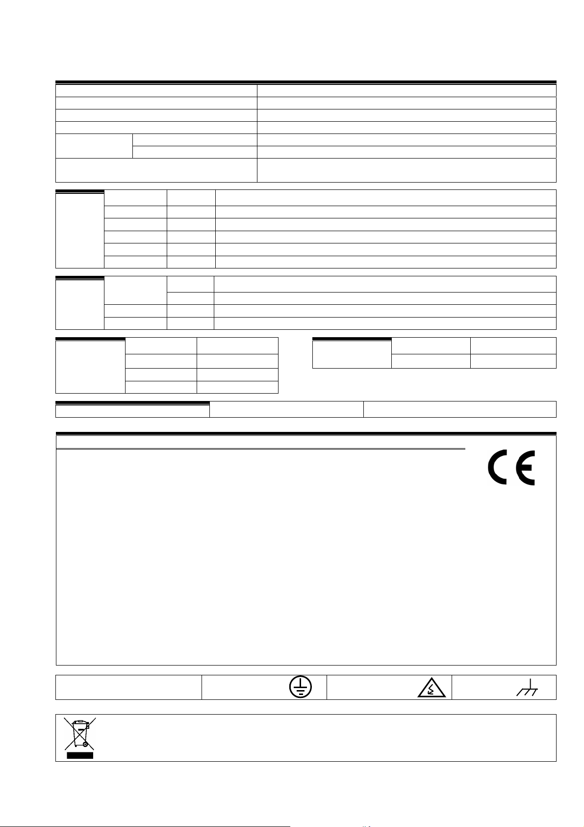
5. TECHNICAL CHARACTERISTICS
Power supply
Tension 230 Vac or 115 Vac+5% -10% CAT II
Frequency 50-60 Hz
Energy consumption Below to 43 VA
Input 0,800 A, T type, 250 V (slow) Fuses
Output 6,3 A, F type, 250 V (fast)
Keeping the memory which can be erased
when there is a power cut
Outputs
Digital Number 16 extensible to 24, 32, 48, 64, 80, 96.
Type By relay contact, with potential of 24 VAC (External transformer)
Limits 30VAC / 30VDC, 1 Amp, 50-60 Hz, CAT II
Analog Number 2
(option) Type By voltage of 0 to 10 volts.
All outputs have double isolation in reference to the net input.
Inputs
Number 12 Digital
Type Optolinked, work at 24 VAC
Analog Number 4
(option) Type 4-20 mA, 0-5 V.(with galvanic separation)
Atmosphere
Temperature 0ºC to 45ºC Box model Built-in model
Humidity <85%
Height 2000m
Pollution Grade 2
Memory backup Clock and data Above to 5 years.
DECLARATION OF CONFORMITY
It follows the 89/336/CEE guidelines for the Electromagnetic Compatibility and the
73/23/CEE guidelines of Low tension for the fulfillment of the product security. The fulfillment of the following specifications was demonstrated as indicated in the Official Diary of
the European Communities:
Lithium Battery, at 3 V.
Weight
(Kg.)
From 3.2 to 6.3 From 4.0 to 5.0
15
Emissions EN 50081-1:94 EN 55022:1994 Type B Radiated and conducted emissions.
Immunity EN 50082-1:97 EN 61000-4-2 (95) Immunity to electrostatic discharges.
EN 61000-4-3 (96) Immunity to the electromagnetic field of radioelectric fre-
quency.
EN 61000-4-4 (95) Immunity to fast transitional in gusts.
EN 61000-4-5 (95) Immunity to crash waves.
EN 61000-4-6 (96) Current injection
EN 61000-4-11 (94) Variations to the power supply.
Harmonics EN 61000-3-2 (95) Current harmonics.
Fluctuations EN 61000-3-3 (95) Tension fluctuations (Flickers).
Low tension guidelines: EN 61010-1 Security requirements of measurement electric units, con-
trol and use in laboratory.
Symbols which may appear
in the product
Protection earth
terminal
Danger, risk of
electroshock
Box terminal
This symbol indicates that the electrical and electronic equipment should not be disposed of as general household waste at its end-of-life. Instead, the product should be handed over to the applicable
collection point for the recycling of electrical and electronic equipment for proper treatment, recovery
and recycling in accordance with your national legislation.
Page 16
16
6. PARAMETERS
In order to install the unit, it is necessary to enter
in the section of “Parameters” to adapt it to the particular necessities of each installation. Press “FUN”
(functions) and choose the function by its number (4).
Then press “Enter".
Programs : 1 Readings : 2 Erasure : 3
Parameters: 4 Manual : 5 Clock : 6
There are 9 options to choose in the “Parameters” menu:
PARAMETERS Fertilis.: 1 Cleaning : 2
Generals : 3 Inputs : 4 Flows : 5
PARAMETERS Sectors : 6 Programmes : 7
Comunication: 8 Miscellaneous: 9
In order to get placed in one of the two screens of
the menu, press the up and down arrow keys. Then
press the number of the option and the “Enter” key.
6.1. FERTILIZATION PARAMETERS
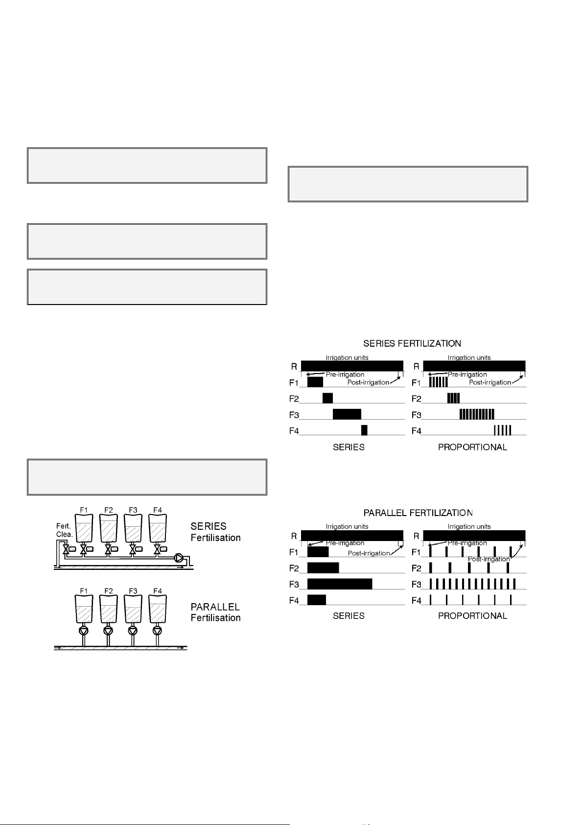
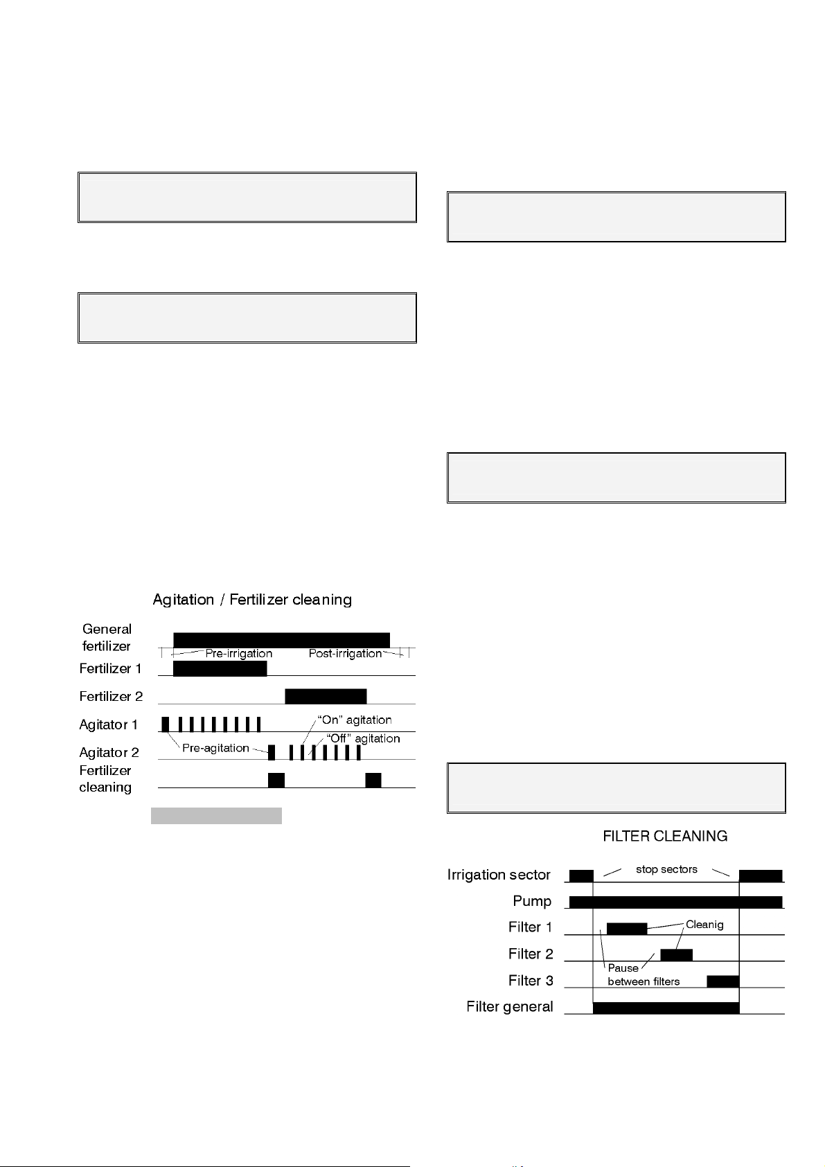
and in its totality when it is programmed in parallel.
They stop when the programmed units in one of them
finish. Look at the explicative drawings.
The proportional fertilization consists in apply-
ing each type of fertilizer not one after the other but in
several activations, with doses which will maintain a
prefixed proportionality in relation to the amount of
water circulating.
Proportional Fertilization (Y/N) : YES
F1 005/012 F2 005/014 F3 005/009 F4 010/002
If the proportional modality is chosen, at the series application format will ask for the proportions for
each one of the fertilizers and at the irrigation programs, the total quantity of water and fertilizer to be
applied to the crop will be programmed.
For example, the proportion “010/002” corresponds to 10 irrigation units per each 2 fertilizer units.
These units can be in time (hours: minutes, minutes’
seconds’’) or in volume (m
3
, L, dl, cl), in relation to the
units each sub-program has.
Of the 8 possible fertilizers, the ones which are
going to work have to be configured. It has to be also
defined if the fertilization will be in series [1] (apply
one fertilizer after the other) or in parallel [2] (apply
several at a time).
Fertilisers number ( 0 – 8 ) : 3
Fertilisation series (1) parallel (2) : 1
Each one of the types of fertilization can be configured to be applied one after the other or proportionally to the irrigation units.
As shown in the picture above, the series fertili-
zation applies each one of the fertilizers for the total of
the programmed value once its addition starts. When
the series fertilization is programmed the totality is
applied before the next one. They are applied at a time
At the parallel fertilization modality it does not ask
here for the proportions of the different fertilizers, but it
does for each one of the irrigation programs.
The pre-irrigation and the post-irrigation are independently programmed in each program.
The way of acting of the proportional modality is
the next: the pre-fixed pre-irrigation is done, it applies
the programmed water/fertilizer proportion, when the
fertilizer units conclude, it will wait until the irrigation
units of the proportion conclude and it will apply another proportional cycle. It will continue this way until
arriving at the post-irrigation or end of the irrigation in
the parallel application or it will wait until the fertilizer
units of the program conclude in the series one.
Page 17
17
The unit allows to do a cleaning of the pipe lines
and injector with water at the end of each fertilizers at
the series application or at the end of them all in the
parallel one. If no cleaning is desired, leave the cleaning seconds at 0.
Fertilizer end cleaning : 018”
Each fertilizer can have its associated mixer, with
independent pre-mixing set on mixing and stop mixing
values.
Mixer 1 Pre-mixing : 035”
On/off mixing : 015” / 120”
The pre-mixing will enter when the irrigation in the
pre-irrigation units start. If pre-mixing is not desired
leave the value at 0.
The mixing will enter when starting the correspondent fertilizer and will constantly act during the
whole application of the fertilizer if value is only given
in the set on seconds. If value is only given to the stop
seconds, there will not be mixing. Programming the
set on and stop temporization, the mixing will be intermittent.
At the proportional fertilization modality, the mixers will act without having in consideration the pauses
of the fertilizer.
of “General outputs parameters” to configure the
number and the outputs of each group of filters.
Each group of filters is independent, in its con-
figuration and operation, to the others.
First it will ask which group the values will be en-
tered for.
Filters group number : 1
To apply the cleaning two times can be programmed, of utility, for instance, when there are both
rings and sand filters, or when there is a first filter
which gets dirtier than the other ones. In case of being
the cleaning time common to all the filters of the
group, the values of the second subgroup will be left
at 0.
Let’s see a configuration example of a filters
cleaning group: there are 8 filters. The 4 first have a 30
second cleaning time and the others a two minute
time.
Cleaning time: 030” sub-g. 1 : 01 a 04
Cleaning time: 120” sub-g. 2 : 05 a 08
The pause time between filters is the delay in the
starting of each filter’s cleaning.
The units between cleanings correspond to the
time or volume of water circulating through the filters
to make a new cleaning of them. The units will be in
minutes, cubic meters or liters, depending on what
programmed in the “Irrigation units” of the “Flow parameters” (6.5).
The cleaning can also be started by a differential
pressure gauge connected to a digital input. Whenever a filter cleaning takes place, the counter of units
between cleanings is reinitiated.
In order to avoid the filters cleaning by units,
leave the value at 0.
[ values for pH/EC control option ]
[Every time a sentence like this appears in shading letters, it means more screens will appear when
having this option activated. To work with this option it
is necessary to have it discharged and to have the
supplement to the explanation manual of this one.]
6.2. FILTER CLEANING PARAMETERS
The filters cleaning is another important service of
the Agrónic range which allows to clean periodical
and automatically the four possible groups of filters by
means of a sequenced cleaning.
Before configuring the values for the cleaning of
this sector, it is necessary to enter in the sector [6.3]
Pause time between filters : 04”
Units between cleanings: 02300
Answering affirmatively to the “Stop sectors when
cleaning” request, the sectors which have common
irrigation pumps assigned with those assigned to the
Page 18
18
filters cleaning will temporary stop. Once finished, the
sectors will continue at the same point where they
stopped.
In order to avoid a continued filter cleaning, a
maximum number of cleanings can be configured.
When the programmed value is surpassed it enters in
the “Filter cleaning without control” malfunction. In
order to reactivate the cleaning go to the “manual”
function, “malfunctions” sector and stop it.
In order to count a cleaning as a continued one,
the time between one cleaning and another must be
of 5 minutes.
In order to avoid the control, leave the value at 0.
Stop sectors when cleaning : YES
Max. Num. of cleanings in a row : 3
At the following screen, the pumps and volume
counters are assigned to the filters group. With this the
next features are reached:
• Count the time between cleanings when
pumps irrigating and coinciding with the assigned in this sector, whenever at flow parameters the irrigation had been configured in
units of time.
• Count the volume between cleanings when
pulses of the volume counters coinciding with
the assigned here arrive, whenever at flow parameters the irrigation had been configured in
units of volume.
• Start the pumps configured here when the
stop of the irrigation sectors in the filters
cleaning has been ordered.
• Take into account the differential pressure
gauge correspondent to the group of filters,
whenever that any pump of the ones assigned
here is set on.
In relation to P 1 2 3 4 C 1 2 3 4
Y Y N N Y Y N N
6.3. GENERAL OUTPUTS PARAMETERS
The general outputs necessary for the correct
working of the installation are configured in this sector.
Each function (pump, fertilizer, mixer, filter, etc.)
is assigned an output relay. This can be placed at the
base of the unit or in distance external modules by
cable or radio. Section 4.6.1 specifies how the eight
digits of the outputs are coded.
The Agrónic 4000 can control 4 independent irrigation pumps which will automatically start or stop if
irrigation sectors are set on and have the pump assigned.
An output relay has to be assigned to each
pump. In case of avoiding the use, leave the value at
0.
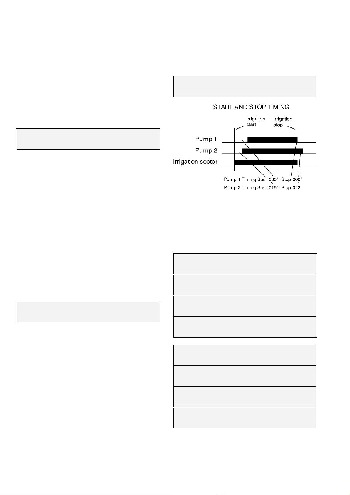
The start temporization corresponds to the time
the activation of the relay will be delayed since the
start is ordered. If the value is set at 0, the output activation is immediate.
The stop temporization keeps the output activated as long as programmed here when the order of
stop arrives. At 0, the deactivation is immediate.
Pump 1 Nº of output : 00000024
Temporisation on/off : 022” / 005”
The following four screens will be used to assign
output relays to the fertilizers and mixers set in the
installation. The ones which are not going to be used
will be left at 0.
In case of a common mixing to all the fertilizers,
the same output relay has to be assigned to all the
configured mixers.
Fertilizers F1 F2
Nº of output : 00000020 00000019
Fertilizers F3 F4
Nº of output : 00000000 00000000
Fertilizers F5 F6
Nº of output : 00000000 00000000
Fertilizers F7 F8
Nº of output : 00000000 00000000
Mixers F1 F2
Nº of output : 00000017 00000016
Mixers F3 F4
Nº of output : 00000000 00000000
Mixers F5 F6
Nº of output : 00000000 00000000
Mixers F7 F8
Nº of output : 00000000 00000000
If necessary a fertilizer general output can be
configured so that whenever one is activated, the
general one is activated too.
Page 19
19
When applying water is necessary for the fertilizer
injector cleaning, an output relay will be assigned.
Fertilizer general output : 00000000
Fertilizer cleaning output : 00000000
An auxiliary output may be assigned for each of
the fertilizers. The output number of the relay may be
common for various auxiliaries, with which for example
can be obtained different fertilizers.
Auxiliary Fert. F1 F2
Nº of output : 00000025 00000025
Auxiliary Fert. F3 F4
Nº of output : 00000000 00000000
Auxiliary Fert. F5 F6
Nº of output : 00000000 00000000
Auxiliary Fert. F7 F8
Nº of output : 00000000 00000000
In this chapter it will be configured the filters
number for every one of the 4 independent groups
that the unit can control, in order to automatically
clean the filters.
For every group (G1-G4), enter the output relay of
the first filter and the last one, in the next example it is
assigned the 15 output for the first one and the 18 for
the last one, with this it is defined automatically the
control for 4 filters, always it has to be set from minor
output to higher. If it is necessary, it can be used a
general output that it will be activated anytime that a
cleaning of any filters group will be carried out, left to
“0” when it will not be used.
The other filters configuration values are introduced in the chapter [6.2.] of “Parameters cleaning
filters”.
When there are a filters group not used, leave the
values to “0”.
Filters outputs G1: 00000015 to 00000018
Filters general outputs G1: 00000000
The units dispose of two alarm outputs, one of
general character and the other related to the fertilization.
When the use is required, the correspondent outputs will be assigned in the unit.
General alarm output : 00000000
Fertilization alarm output : 00000000
The alarm outputs will be activated when an
anomaly takes place. The section “Anomalies reading”
shows which anomalies will activate the alarm if nothing is set, although at the “installer configuration” the
fact of activating or not the alarm at each anomaly can
be modified.
The alarm outputs can act intermittently by giving
start or stop temporization, or fixed by giving them
when working.
The alarm output can be normally open (YES) or
normally closed (NO) configured, in order to have the
chance of activating sirens or telephone advisers, for
example:
Alarms, temporization, on/off : 008” / 030”
Alarm output normally open (Y/N) : YES
[ values for pH / EC Control option ]
[ values for DIESEL Control option ]
6.4. INPUT PARAMETERS
There are two kinds of inputs, the digital ones to
connect elements which act by contact (differential
pressure gauge, level, counter, etc.) and the Analog
ones for sensors which give a proportional signal to
the magnitude that has to be measured (temperature,
sun radiation, humidity, etc.)
Once the “Inputs” option has been chosen at the
“Parameters” menu, the following screen will be
shown to choose the type of input to configure.
INPUT PARAMETERS
Digitals : 1 Analogs : 2
6.4.1. Digital inputs
Each input can be assigned a function in order to
act in a pre-determined way when connecting.
Function code number : 00
At the following list the different function codes
and the request it makes to each of them are described:
• Code 01: General Malfunction
• Code 02: Differential pressure gauge 1
• Code 03: Differential pressure gauge 2
• Code 04: Differential pressure gauge 3
• Code 05: Differential pressure gauge 4
-Detection delay: 030”
• Code 06: Stop 1
• Code 07: Stop 2
• Code 08: Stop 3
• Code 09: Stop 4
- Detection delay: 030”
- Conditional, Temporary, Definitive
- Show it as an Anomaly Y/N?
• Code 10:Intrusion alarm
- Detection delay
Page 20

20
• Code 11: Irrigation counter 1, pulses
• Code 12: Irrigation counter 2, pulses
• Code 13: Irrigation counter 3, pulses
• Code 14: Irrigation counter 4, pulses
-Pulse value: 01000 L
-Maximum time between pulses: 240”
• Code 15: Fertilizer counter 1, pulses
• Code 16: Fertilizer counter 2, pulses
• Code 17: Fertilizer counter 3, pulses
• Code 18: Fertilizer counter 4, pulses
• Code 19: Fertilizer counter 5, pulses
• Code 20: Fertilizer counter 6, pulses
• Code 21: Fertilizer counter 7, pulses
• Code 22: Fertilizer counter 8, pulses
-Pulse value: 0100 cl
-Maximum time between pulses: 200”
• Code 23: Irrigation counter
1, frequency
• Code 24: Irrigation counter 2, frequency
• Code 25: Irrigation counter 3, frequency
• Code 26: Irrigation counter 4, frequency
-Cycles per litre: 009.43 Hz
• Code 27: Fertilizer counter 1, frequency
• Code 28: Fertilizer counter 2, frequency
• Code 29: Fertilizer counter 3, frequency
• Code 30: Fertilizer counter 4, frequency
• Code 31: Fertilizer counter 5, frequency
• Code 32: Fertilizer counter 6, frequency
• Code 33: Fertilizer counter 7, frequency
• Code 34: Fertilizer counter 8, frequency
-Cycles per centiliter: 128.50 Hz
• Code 35:
-Liters per pulse: 00.5 L/m
Rain gauge
2
• Code 36: Start 1 of programs
• Code 37: Start 2 of programs
• Code 38: Start 3 of programs
• Code 39: Start 4 of programs
• Code 40: Start 5 of programs
• Code 41: Start 6 of programs
• Code 42: Start 7 of programs
• Code 43: Start 8 of programs
-Detection delay: 030”
-Stop Y/N : NO
[ values for DIESEL Control option ]
Once the function has been entered, the number
of input has to be chosen, to do so, take into account
the chart of the section 4.6.2.
Sector 4.3.3 has to be taken into account to deal
with the installation and the connection.
For most of the inputs there is a common value
which is the “Detection delay”. This temporization
guarantees the time the input has to keep connected
to carry out its function.
The “General malfunction” function is used to
stop completely the unit due to the connection of a
security element. It is necessary to have any pump
general output operation in order to have the chance
of acting.
When a malfunction has taken place and then it
has been repaired, the “Manual Function” has to be
used in order to finish it and continue with the irrigation proceeding at that moment at the same point
where it stopped.
Each one of the four filter group the unit allows
can start the cleaning by connecting a “Differential
pressure gauge”, which measures the difference of
pressure between the input and output of the filters.
When the power is switched on and the irrigation is
working, after the “detection delay“ temporization, it
will clean the filters.
For the 06 to 09 “Stop” functions, the input operation can be configured in three different ways, besides this, the stop inputs that each irrigation sector
has to use are configured at the “Sector parameters”
sector.
The ”Temporary
” one will cancel the irrigation of
the sector or group of sectors in order to go to the
following sub-program. If the program is reinitiated, it
will try to irrigate the sectors were previously affected
by the input.
With “Conditional
” the irrigation of the sector or
group of sectors is stopped and adjourned as long as
the input is connected. Once the input is disconnected, the irrigation will continue at the same point
where it stopped.
At the “Definitive
”, all the sectors assigned to the
input will stop operation definitively. Enter at the
“Function-Manual-Malfunctions” to end the stop.
If in an irrigation program, a group of sectors is irrigating and a “Stop” input is activated, all the group
will stop irrigating, even though not all of them are
assigned to the input.
The “Intrusion alarm” function is used to protect
from vandalism the installation. To do so, connect the
protection elements such as radars, door sensors, etc.
in series with the normally closed contacts, to the input; the first one that opens, after the detection delay
temporization, will activate the alarm output and, if the
SMS messages option is installed, will send a text
message to a mobile phone (SMS messages sending
option).
The four possible irrigation counters, functions
11 to 14, can work with pulses transmitter from 1 to
10.000 liters.
It is necessary to enter the value in seconds of
the time between two pulses with the lowest operation
flow at the “Maximum time between pulses
tects the fact that there is no irrigation flow. As an example, we will calculate the time for a flow of 2 m
and a counter of 100 liters:
”. This de-
3
/h
2.000 L/h ÷ 3600 = 0,5555 L/sec.
100 ÷ 0,5555 = 180 seconds.
Page 21

21
It is important to give this value when doing the
control by lack of flow.
The Agrónic 4000 allows us, as well, to work with
the irrigation counter by frequency, asking for the
cycles per liter the counter sends. At the counter
specifications the cycles per liter in relation to the diameter of the pipe line will be indicated.
For the Fertilizers counters (codes 15 to 22 and
27 to 34), the operation philosophy is the same as that
for the irrigation ones, with the difference that the
pulse value is in centiliters (100 centiliters = 1 liter),
from 1 to 1.000 centiliters. When operating by fre-
quency, the cycles have to be entered per each centiliter (cl).
Functions 23 to 34 of the frequency counters can
only operate with inputs 1 to 7 of the Agrónic 4000
base.
The “Rain gauge” function, number 35, is used
to count the liters per m
2
of precipitation, to do so,
enter the value corresponding to each pulse given by
the rain gauge at the “liters per pulse
” question. Further on we will see it can be used to condition the
irrigation and for the history record. The digital input
that has to be used is number 12.
A total of 8 inputs, with function codes 36 to 43,
are configured for the ”Programs starting”, will set
the starting of an irrigation program configured to be
conditioned by the input (section [6.7] of ParametersPrograms). The question “Stop Y/N
” allows answering
“YES”, to stop the program by its input when disconnecting it, and with “NO” it will only do the start, finishing when the application of time or volume programmed ends.
6.4.2. Analog inputs
The Analog inputs sector has to be chosen at the
“Parameters-Inputs”
INPUTS PARAMETERS
Digital : 1 Analog : 2
The unit offers to control up to a total of 76 different sensors. Each one will be configured an input
where the units of the magnitude to be measured, the
input voltage levels, the screen margins and the calibrate will be connected.
Sensor number (1 – 76) : 02
A sensor can be connected to different elements
of the Agrónic 4000 system. In order to define it, use
the chart of the section 4.6.3.
Sensor 02
Input number : 00000000
The measure unit each sensor will use is defined
at the following screen.
Sensor 15
Measure unit : 02
The codes corresponding to each unit of meas-
ure are defined below:
Metrics USA
00: Null Null
01: ºC ºF Temperature (+00,0 ºC-ºF)
02: Wm
03: cbar cbar Soil moisture (000.0 cbar)
04: %HR %HR Relative humidity (000 %HR)
05: km/h m/h Kilometers hour (000 Km/h - m/h)
06: % % Relation (000 %)
07: Uts Uts Units (0000 Uts)
08: mm Inch Level (000 mm - in)
09: L gal Volume (0000 L - gal)
10: L/m
11: m
12: bars psi Pressure (00.0 bars - psi)
13: mS mS Conductivity (00.0 mS)
14: pH pH Acidity (00.0 pH)
15: mm/d mm/d Evaporation (0.00 mm/d)
16: ’ ’ Temporization (0000 ’)
17: rpm rpm Rev. per minute (0000 rpm)
18: mm mm Displacement (±0.00mm)
19: V V Voltage (00.0 V)
2
Wm2 Solar radiation (0000 Wm2)
2
rain Rainfall (00.0 L/m2 - “rain)
3
/h GPM Flow (000.0 m3/h - GPM)
This allows us to avoid the limitations of the sensors type. Each one of the Analog inputs can be configured depending on the sensor needed, all the
same, all different, or mixed.
For each sensor the voltage margins the input
gives have to be configured and then the correspondent reading the screen will show. At the following
example, we see that a radiation sensor with a 4-20
mA input connected to a radio module will generate a
0.4 V voltage for 0 Wm
2
and 2 volts for 2000 Wm2.
Sensor 15
Input margin min.: 0400 max.: 2000 mV
Sensor 15
Reading min.: 0000 Wm2 max.: 2000 Wm2
The following items have to be taken into account in the installations with sensors:
• Use a screened cable when connecting the
sensors.
• Lay the cable away from the power lines.
Page 22
22
• Try not to surpass the inputs voltage limits.
• The voltages generated by the sensors with
outputs 4-20 mA in the different units are =
- In amplification of the base and Microisis
(200 ohms) is 800 to 4000 mV.
- In expansion modules (150 ohms) is from
600 to 3000 mV.
- In the radio modules (100 ohms) is from
400 to 2000 mV.
In order to calibrate the sensor when its reading
is higher than the real one, the “calibrate” value has to
be diminished below 100, and increased when the
reading is lower.
Sensor 15
Calibrate (100 = 0) : 100
For example, a temperature sensor records an error of an excess of 0.5 grades. It will be compensated
in the calibrate by entering 95.
The evaporation value may come from µMetos,
from a SMS message or be entered manually here, in
the sensor configuration.
6.5. FLOW PARAMETERS
This section is used to configure the constant use
of a unit when programming the irrigation and the
fertilizers. Whenever the unit of this sector is changed,
it will be changed as well in the programs which have
not got a sector assigned yet, taking into account that
with the “T/V” key the irrigation and fertilizer units can
be changed when placing the cursor on the program
value, and per program.
The irrigation units can operate in hours/minutes,
minutes/seconds, cubic meters or liters.
Irrigation units =
hh:mm (0) mm’s” (1) m3 (2) L (3) : 2
The fertilization units can be in hours/minutes,
minutes/seconds, liters, deciliters or centiliters.
(10dl=1L, 100cl=1L)
Fertilization units =
hh:mm (0) mm’ss” (1) L (2) dl (3) cl (4): 2
The flow margins of each counter are used to detect possible flow anomalies, in relation to the expected flow of the sectors related with the counter
which is irrigating at the moment. The maximum volume that the controller can control is 650.00 m
irrigation meters, and 650.00 L/h in fertilizer meters. In
installation parameters there is the possibility of increasing it to 6500.0 m
3
/h o L/h. If the anomaly lasts
3
/h in
longer than the time stated in the “Detection delay”,
the unit will work according to what is set at “Stop
type”.
• With "it does not stop (0)" it will only record the
anomaly.
• With "temporary (1)" it will also cancel, in a
temporary way, the irrigation of the group of
sectors which is taking place, and that have
any sector assigned to the counter to go to
the next one.
• With "definitive (2)" it will definitively stop the ir-
rigations of the controller.
To start again after a definitive stop by flow, this
has to be cancelled from the “Function-Manual”.
Setting the delay at 0 seconds, there is no control
of anomalies by flow.
Irrigation counter 1
High/low nominal flow margin : 25 / 30 %
Irrigation counter 1
Detection delay : 280”
Irrigation counter 1
Stop type, NO (0) Tem. (1) Def. (2) : 1
The irrigation “starting delay” is a common to the
four counters value. An extra delay is allowed when
starting the irrigation in the counter. It is also of use to
avoid entering in flow anomaly when filling the pipe
lines.
Delay at irrigation starting : 480”
6.6. SECTORS PARAMETERS
The Agrónic 4000 can control up to 99 irrigation
sectors. The values of them all are configured in the
following screens.
The values are shown in three screens. To go
from one to the other the right and left arrow keys will
be used. To get placed in another sector, press the up
and down arrow keys.
SECTOR Relay
- 01 - 00000000 YNYN
SECTOR Tempo. Aux. F1F2F3F4
- 01 - +045” 00000045 N N N N
SECTOR Self.pH T.auto Bars
- 01 - 33 % 04” 03.2
P1 2 3 4 SI1 2 3 4 IC m3/h
YYNN
2 088.25
Page 23
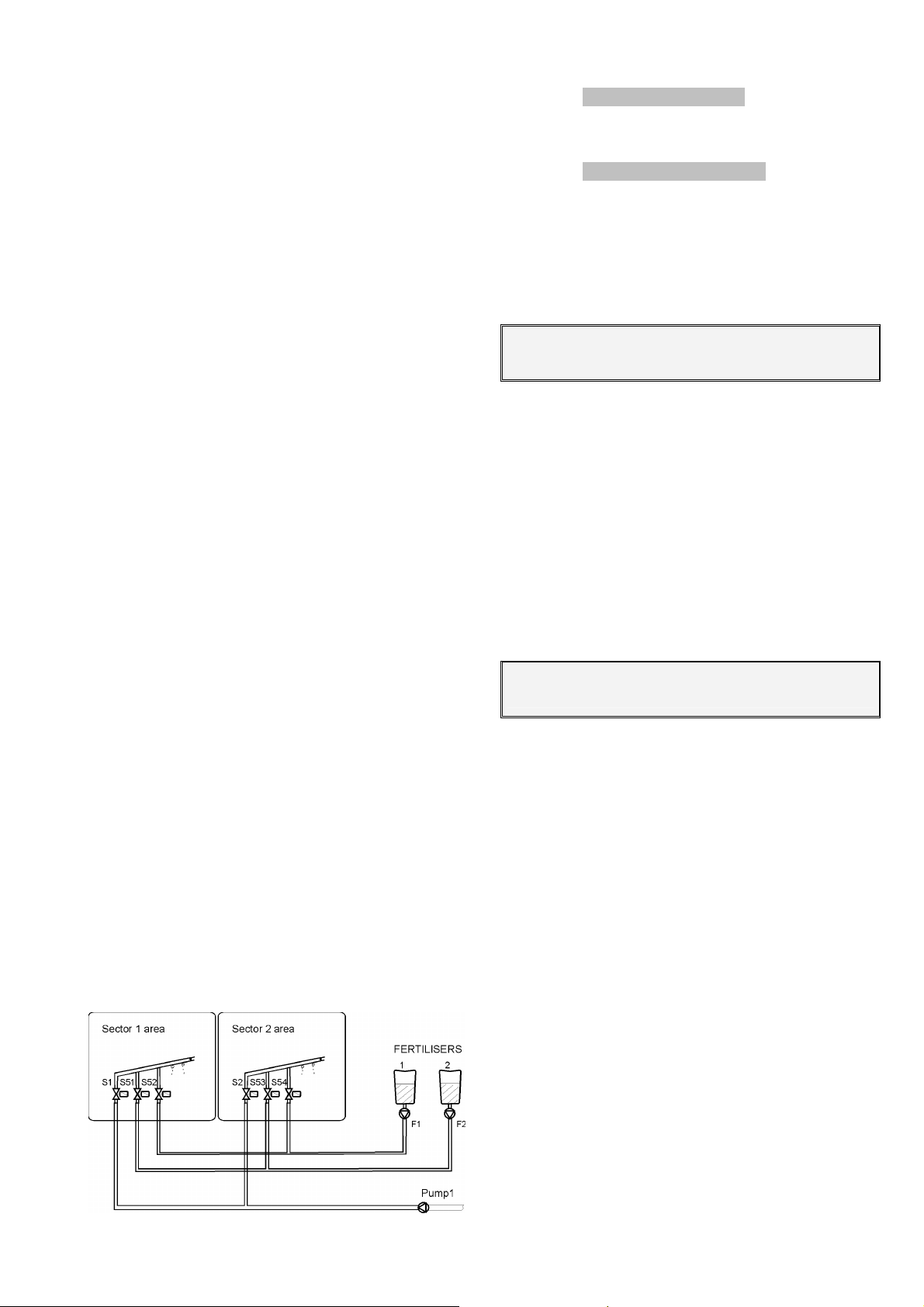
23
Each sector will be assigned an output “Relay”;
this one can be placed at the base of the unit or in a
external modules by cable or radio. Take into account
the chart of the section 4.6.1when the output number
is required:
Each sector can be assigned to one or more
among the four “P1234” pumps and among the four
“SI1234” stop inputs. When entering “YES” a pump, it
will automatically activate when the sector activates. In
the same way, when the sector is activated the stop
inputs (temporary, conditional or definitive) marked
with “YES” will be taken into account.
Each sector can be related to one of the four irri-
gation counters “IC”; once it is assigned and the sec-
tor carries out the irrigation, it will be taken into account for the flow control, for the totals and when programming the irrigation by volume.
The “m3/h” value corresponds to the foreseen
flow which is calculated of consume to the sector. It
will be of use when controlling the flow and when distributing the irrigation and fertilizers volumes in the
totals, when more than a sector is irrigating with the
same irrigation counter.
The “Temporization” is used to delay the sector
activation at the beginning of the irrigation, in case of
negative temporization (-030”), yet for delaying the
deactivation at the end of the irrigation, in case of
positive temporization. (+030”).
Each sector can be assigned an auxiliary relay
output “Aux” which can be common to several sectors. It will be activated each time a sector which has
the same relay as an auxiliary activates. As many general valves as needed it can be generated this way.
The fact of assigning a sector to a fertilizer avoids
the output activation unless the fertilizer which has
been assigned it is activated. This operation way is of
utility in installations where each sector has an irrigation valve, fertilizer 1 valve, fertilizer 2 valve, etc.; the
fertilizers valves would correspond to sectors with
assignation. When programming, these ones are entered in the same way as the irrigation ones.
The sectors assigned to a fertilizer are not irrigation sectors any more. Just one fertilizer can be assigned to each sector.
Only the first four of the 8 disposable fertilizers
are suitable to be assigned.
Look at an example of this system:
[ values for pH / EC control options ]
pH injection self adjustment “Auto. pH”.
Self adjustment temporization “T. Auto”.
[ values for Pressure regulation option ]
Pressure for the irrigation sector “Bars”.
6.7. PROGRAMS PARAMETERS
First of all, the program number has to be cho-
sen.
Program number: 03
Each program can be a part of an “Irrigation
group”. This avoids the irrigation of two programs of
the same group at a time. One of them will be at stand
by showing in its view the text “Postponed by priority”.
The programs assigned to the group “0” do not take
part of an association and avoid the postponement.
The “Security time between starts” is used to
maintain minimum time between two starts. The security is not taken into account when leaving the value at
0.
These functions are of utility, for instance, when
the irrigation start is ordered by sensors, reaching an
organized evolution of the irrigations.
P03 Irrigation group : 0
Security time between starts: 03:45
Each one of the 40 programs has got 4 possible
determiners in order to carry out start actions, stop
actions, irrigation or fertilizers modifications, according
to the following chart:
- Type 01: Start when the sensor surpasses the pro-
grammed value.
- Type 02: Start when the sensor is below the pro-
grammed value.
- Type 03: Start by integrating the value of a sensor.
- Type 04: Start by digital input.
- Type 05: Conditional stop when the sensor sur-
passes a programmed value.
- Type 06: Conditional stop when the sensor is be-
low a programmed value.
- Type 07: Irrigation modification by integrating the
value of a sensor.
- Type 08: Irrigation and fertilizer modification by in-
tegrating the value of a sensor.
- Type 09: Fertilizer modification by integrating the
value of a sensor.
- Type 10: To modify the irrigation in ratio to the
value of a sensor (evapotranspirationEto, ground moisture-cbars - %, etc).
- Type 11: To modify the fertilizer in ratio to the value
of a sensor.
Page 24
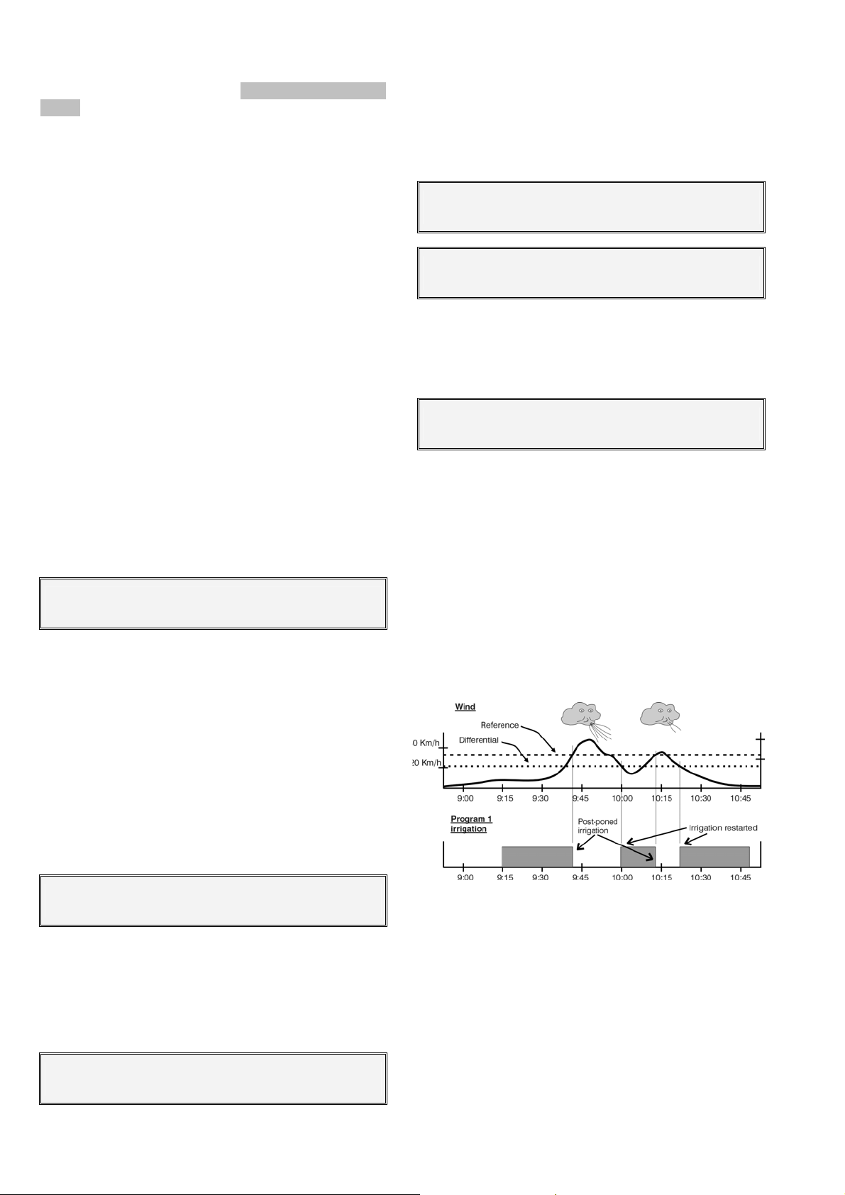
24
[ Types 1,2,3,7,8,9,10,11 are Programs determiners
option ]
The determiner factors can be digital or analog
elements, which can influence the programmed values
in order to adapt them to the climatic or environmental
changes or changes of the installation itself.
This takes place in two stages:
1. At program parameters the determiner factors
that can affect the program and how the determiner will be dealt have to be indicated.
2. At the beginning or at the determiner factor in
each program.
Type 1 and 2 determiners: Having the option in-
stalled, irrigation programs will be started when the
sensor level (temperature, soil moisture, etc.) reach a
determined value. This value will be asked at the irrigation program as well as the starting time when
pressing the “mode” key.
The determiner will be only taken into account
when the irrigation is not taking place and when sixty
seconds have passed since the sensor value has
reached and maintained the starting value.
By answering “YES” to the “Generates a message Y/N” question, a SMS message will be sent to a
mobile telephone, whenever the option has been installed. This question appears in all types of start and
stop determiners.
P01 Determiner 1, type: 02
Sensor: 04 Generates a message Y/N : YES
Type 3 determiner: Having the option installed,
irrigations by integration (total of sensor units in relation to time) can be started. For example, we can integrate with the solar radiation de vats/hour the plant
has received since the previous irrigation and order
more frequent irrigations in sunny days than in cloudy
ones.
The sensor number and a minimum level, from
which the integration will be allowed, have to be entered. At the irrigation program, next to the starting
time and pressing the “mode” key, the integration
value since the previous irrigation will be asked in
order to deal with a new irrigation.
P01 Determiner 1, type : 03
Sensor: 01 Min.: 0200 Wm2
Type 4 determiner: It allows the starting of irriga-
tion programs by a connected to a digital input element with a starting programs function. Look at [6.4.1
codes 36-43] sector.
Enter which start input functions out of the 8 possible ones will affect the program.
P01 Determiner 2, type : 04
Starting F. = 1 Generates a message Y/N : Y
Types 5 and 6 determiners: They are used to
stop conditionally or temporarily an irrigation ordered
by a program whenever the sensor value is not a reference value. Type 5 will stop when the value surpasses the reference and type 6 when it goes down.
P01 Determiner 2, type : 05
Sensor : 16 Temporary? (Y/N): N
P01 Determiner 2, type : 05
Sensor : 16 Reference : 034 Km/h
Immediately, if the stop is conditional a differential (dead band) from which, more in type 6 or less in
type 5, depending on the programmed reference, the
irrigation will be reactivated, will be asked.
P01 Determiner 2, type : 05
Differential : 022 Km/h
If the stop is conditional, not timed, when watering is started again, it will do so from the time at which
watering was stopped.
If the stop is temporary timed, watering will stop
and when it starts again it will move to the next subprogram.
In order to avoid false operations, the sensor level
has to last more than 30 seconds out of the margins to
be operative.
Some examples for the stopping determiners can
be: the fact of stopping a sprinkling due to a wind
excess or stopping due to a lack of pressure in a pipe
line.
Type 7, 8 and 9 determiners: Having the option
installed, the irrigation units and/or the fertilization by
integration (total of sensor units in relation to time) can
be modified. For example, we can integrate with the
solar radiation of vats/hour the plant has received
since the previous irrigation and order a higher time in
volume in sunny days and a lower one in cloudy ones.
The “sensor” number, a “minimum level” from
which the integration will be allowed and a “limit” security value in the integration which in case of being
surpassed will not be taken into account, have to be
entered. In case of having a rain sensor, “99” has to
Page 25
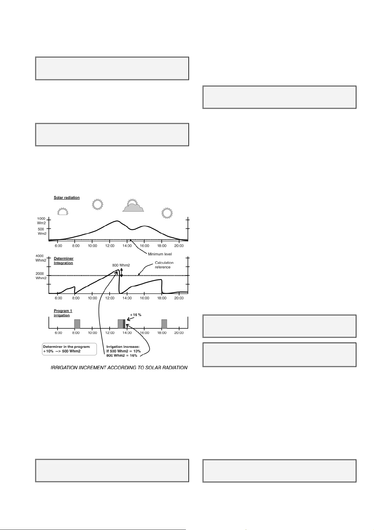
25
be entered in the sensor, meaning it is the digital function of the rain gauge.
P01 Determiner 4, type : 07
Sensor: 01 Min.: 0200 Wm2 Lim.: 12500 Wh/m2
The “calculation reference” is used to define an
integration point of reference above which the value
modification factor which surpasses the reference will
be applied.
P01 Determiner 4, Type : 07
Calculation reference : 02000 Wh/m2
At the irrigation program, next to the manual factor and pressing the “mode” key, the integration value
since the previous irrigation will be asked.
Example:
The “reference for calculation” is used to define a
point of reference in the units of the sensor above
which will be applied the modification factor in ratio to
the value that surpasses the reference, when it is a
positive value, when negative it will be applied upon
going lower than the reference.
P01 Determiner 4, type : 10
Reference for calculation : + 0.80 mm/d
In the irrigation program, next to the manual factor, pressing the “mode” button will ask for the modification factor. In an evapotranspiration sensor the
“crop constant” is used; in other types of sensors
leave the value at 1.00.
Etc = Eto * Kc
Etc = Evapotranspiration of crop
Eto = Evapotranspiration
Kc = Crop constant
6.8. COMMUNICATION PARAMETERS
This section indicates which external elements
will be communicated by the equipment. These elements may be:
- PC program
- SMS messages sending and recep-
tion (GSM only)
- Agrónic Radio 868
- Agrónic Radio 2,4
- Agrónic Monocable
- Expansion modules
- Microisis
- µMetos
The irrigation units can be increased by solar ra-
diation, temperature, etc., or diminished by rain, etc.
Type 10 and 11 determiners: Having the option
installed the irrigation and fertilizer units and can be
modified in relation to the reading of a sensor
(evapotranspiration, soil moisture, etc.).
The number of the “sensor” and the crop constant have to be entered. The units that have to be
used are millimeters per day.
P01 Determiner 4, type : 10
Sensor : 32 Crop Constant : 0.93
COMMUNICATION PC : 1 SMS : 2 GSM : 3
Agr.Rad868: 4 Agr.Rad24 : 5 Agr.Mon. : 6
COMMUNICATION Mod.Exp. :7 MicroIsis : 8
uMetos : 8
It is important to stand out that all the communications are normally non installed options at the base
unit. When this takes place the “-non installed option-”
message will appear on the screen.
6.8.1. Communication with PC program
When linking a PC to several Agrónic 4000 each
one of them have to be numbered in order to differentiate them in the net. Enter the value at “Agrónic Number”.
Communication with the PC:
Agrónic number : 01
Page 26
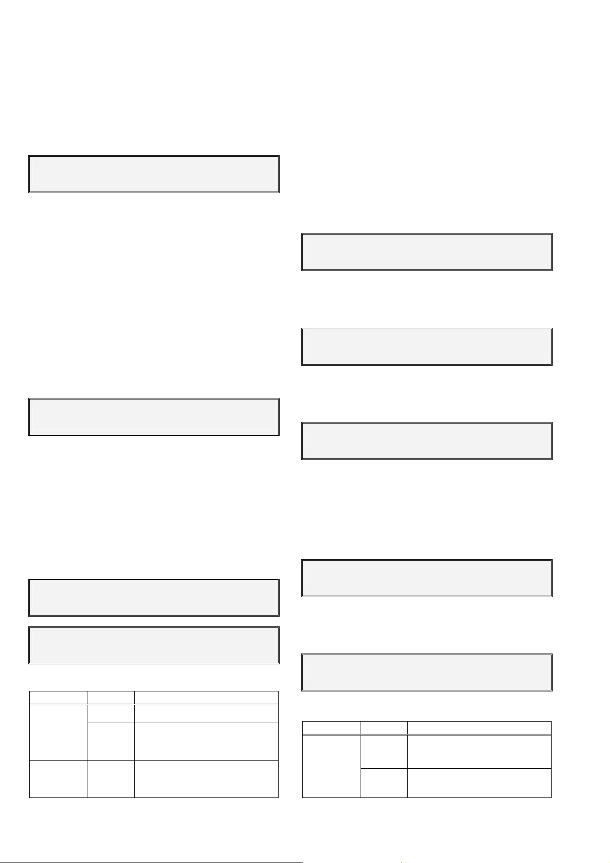
26
The data “Transmission speed” when linking to a
PC can be:
0 – 1200 bps
1 – 2400 bps
2 – 4800 bps
3 – 9600 bps
4 – 19200 bps
Communication with the PC :
Transmission speed : 0
The exit of the data to the PC is done from a “serial port”; the Agrónic 4000 has already installed two
ports and it is possible to amplify with one additional
port.
- Port 1: Link RS232.
- Port 2: Link RS485, in two wires and galvanically
isolated.
- Port 3: Link RS232 (option).
- Port 0: Null, the communication remains dis-
abled.
The RS232 link is used with elements placed beside the controller or at a maximum of 30 meters and
the RS485 for several elements at a time and at distances of hundreds meters.
Communication with the PC:
Serial port : 1
The linking to a PC can be done by cable or “Via
modem”, which can be a conventional one or GSM.
When the link is done by modem, the “modem configuration” chain can be modified.
When linking via modem, a SIM card is required
in order to make calls (it is the same card used at the
mobiles).
In order to modify the texts the up/down arrow
keys have to be used and to move the cursor the
left/right arrow keys.
Communication with the PC :
Via modem : YES
Communication with the PC :
Modem configuration: ATEØVØSØ=2
Compatibility chart:
Link Port Compatible with
1, 3 -Link to PC
via cable
2
- Other Agrónic 4000
- Microisis to PC (not to use
with A-4000)
Link to PC
via modem
1, 3
- SMS messages
6.8.2. SMS messages sending
The SMS messages option is used to send SMS
messages to mobile phones, activity of the day reports or messages about any event or anomaly. In
addition to this, text messages with operation orders
can be sent from the mobile telephone to the Agrónic.
The SMS messages are only applicable when the
modem or the telephone that sends or receives the
message uses the GSM technology.
Two different times of the day are allowed to send
a report; in it the irrigation starts carried out by each
program will be indicated. In order to avoid the sending, leave the time at a 00:00.
SMS messages : YES
Report time 1 : 18:00
The “Services centre” number which has been
contracted to the GSM modem card connected to the
A-4000 has to be entered.
SMS messages : YES
Services centre : 340000000000
The destiny number corresponds to the telephone which will receive the message. The numbers
have to be initiated by the country code.
SMS messages : YES
Destiny telephone : 340000000000
The “Transmission speed” can be:
0 – 1200 bps
1 – 2400 bps
2 – 4800 bps
3 – 9600 bps
4 – 19200 bps
SMS messages: Y.
Transmission speed : 0
It is necessary to enter the serial port number
which will communicate with the modem. Look at section “6.8.1” for further information about the ports.
SMS messages: Y.
Serial port : 1
Compatibility chart:
Link Port Compatible with
SMS
messages
1, 3 Link to PC via GSM modem
2 -
Page 27
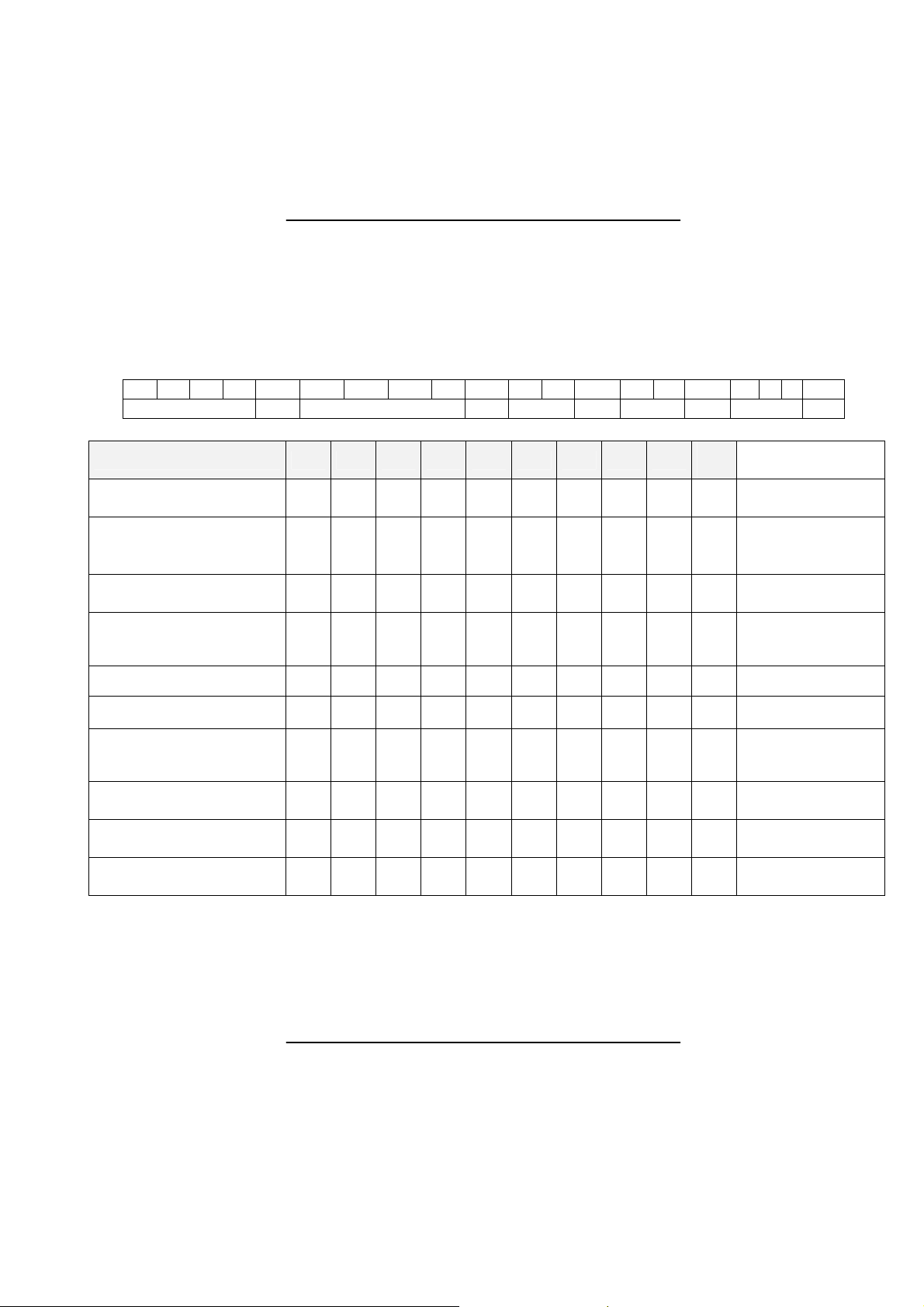
6.8.3. Messages sending from a GSM tele-
phone
When the Agrónic 4000 has the “SMS messages”
option activated and is connected to a GSM modem,
orders can be sent from a digital mobile telephone.
The format the SMS message to be sent to the Agrónic 4000 must have, is the next:
These orders can be to start, stop or modify the
manual factor of the programs, to switch on or off the
STOP, to do a filter cleaning, to give an Analog value,
to deactivate any kind of alarm and to send an immediate report.
27
o Unit series number (4 digits)
o Blank space “Esp”
o Access code (4 digits: entered by the user at miscellaneous parameters)
o Blank space
o Operation code “OP1, 2 ..”(separated by a blank space between them)
S S S S X X X X Z Z Z Z Z .. .
Series number Esp. Access code Spa OP1 Spa. OP2 Spa. OP3 ....
(np
OP
10
Nomenclature
np: program
ns: sub-program.
np: program
ns: sub-program
±00 : factor
±00
np: program
(np
+7)
±00 : factor
Operation code OP1 OP2 OP3 OP4 OP5 OP6 OP7 OP8 OP9
Activate program AP np ns
Activate program with an
irrigation factor for this
AP np ns
±00
activation
Stop the irrigation of a
program
Modify the manual factor
of one or more programs
SP np np: program
±00
±00
±00
±00
MF np
±00
(np)
±00
(np
+1)
(np
(np
(np
+2)
+3)
+4)
(np
+5)
±00
+6)
Switch on or off the STOP ST cd cd= YES, NO
Start a filter cleaning FC gn gn: group number
xxxx
Value for virtual inputs IV se
Deactivate any alarm,
Stop or out of order.
Request for immediate
“Send inform”
Cancel all the text SMS
messages
Examples of messages =
AL
SI
SM
xxxx
(se)
(se
+1)
xxxx
(se
+2)
Xxxx
(se
+3)
Xxxx
(se
+4)
xxxx
(se
+5)
xxxx
(se
+6)
Xxxx
se: sensor number
(se
1 to 8
+7)
"0001 1234 AP 01 01" Start the program 1 irrigation at the sub-program 1.
“0001 1234 AP 05 01 –25” Start pro. 5 at the sub-pro. 1 reducing the irrigation a 25%.
“0001 1234 MF 01 +12 +18 +05” Modify the manual factors of programs 1 to 3.
“0001 1234 ST YES” Set the unit at STOP.
“0001 1234 SM” Cancel the text messages.
Once the message has been received and executed by the Agrónic 4000, it will send a message with
the following text “Message received. Order executed”
to the phone which sent the message (except with SM
code).
The value of sensor virtual inputs has to be entered in the same format that has been configured at
the input. For example, at the most common case of
the evapotranspiration, it is “0.00”.
The “SM” code is used to cancel the text messages, of utility for example, when a message of
anomaly by damaged sensor is constantly repeated.
In order to send messages again, a number has to be
discharged at “serial port” by entering at “SMS messages” [6.8.2] in communications parameters.
Page 28
28
6.8.4. GSM modem checking
When entering at the “GSM” section, the cover
level of the telephone signal which is being received,
the condition of the PIN card and if GSM telephone
network (operator where the PIN is contracted) is
available is shown.
GSM modem checking :
Look at coverage? YES
The coverage is correct based on a level of 17.99.
GSM modem checking:
Look at PIN condition?: YES
GSM modem checking:
Look if net. Available?: YES
6.8.5. Communication with Agrónic Radio 868
This indicates if communication with the Agrónic
Radio is activated or not.
Agrónic Radio communication : Activate : YES
For each of the radio modules it must be specified if communication with it is desired or not.
Agrónic Radio communication:
Communicate with module 01 : YES
If the model is Agrónic Radio 868 these configuration parameters must be entered in the modules.
Agrónic Radio communication:
Enter to module 01 configuration : YES
When entering at the configuration the following
questions will be asked:
- “Action due to communication error (0-1-2): 0”, at
“0” it maintains the status of the electrovalves, at
“1” it closes them immediately, at “2” it closes
them after being 10 minutes without having a correct communication.
- “Potency level (0 a 7): 4
sion potency level.
- “Minutes between sensors readings: 000’
be the cadence with which the readings of the
elements connected to the Analog inputs of the
modules will take place. Leave it at 000’ to avoid
the readings.
”, it is used to fix the emis-
”, it will
- “Sensors power supply x10 ms: 000
”, it is the
time, in units of 10 milliseconds the sensors power
supply will last before doing the reading and deactivate them. It will be used to establish the signal
according to the type of sensor.
- “Blast power greater than 12 VDC : NO
”, to activate solenoid impulse latch to 12 Volts, reply “NO”
and to give the blast greater tension, reply “YES”.
- “It is a translation module: YES
”, in order that a
module can deal with translator functions, “YES”
has to be entered and then assign each module of
which it is a translator.
- “3 wires output latch
”, to connect solenoid impulse latch in 3-wires radio mode enter “YES” and
for two way “NO”.
- “Is MR of level 2?: YES”, will show YES whenever
the MR it at a level of 2 (after the first relay).
- “Start configuration sending
” it is used to update a
module configuration when answering “YES”. It is
necessary that the module to be configured has
the bridge installed to indicate it that it will receive
these special data. Once received the new values
the pilot light will switch off at the module. Then
confirm the question “Finish configuration sending”. For further details look at radio modules
characteristics sheet.
6.8.6. Communication with Agrónic Radio 2,4
This indicates if communication with the Agrónic
Radio2,4 is activated or not.
Agronic Radio 2,4 communication :
Activate : Y.
6.8.7. Communication with Agrónic Monocable
This indicates if communication with the Agrónic
Monocable is activated or not.
Agronic Monocable communication:
Activate : Y.
If the model is the Agrónic Monocable 64 it must
be specified if communication with it is desired or not
Agronic Monocable communication: YES
Communicate with module 01 : YES
6.8.8. Communication with Expansion Modules
This indicates which Expansion Modules are con-
nected to the Agrónic.
Communication with the expansion modules :
Communicate with module 01? YES
Page 29
29
It is necessary to install the internal modem in the
Agrónic 4000 in order to communicate with the expansion modules by two wires of 24 volts of alternate
power.
6.8.9. Communication with Microisis
This indicates if communication with the MicroIsis
is to be activated or not.
Communication with Microisis :
Activate : 2
Communication with MicroIsis :
Communicate to Microisis 1 ? Y.
Communication with the MicroIsis is always
through port 2 (RS485). In this case, the RS485 port
only it may be shared with the µMetos.
6.8.10. Communication with µMetos
This allows activation or deactivation of communication with uMetos. Communication is always
through port 2 (RS485).
6.9. MISCELLANEOUS PARAMETERS
If due to practical needs some programs or sectors want to be copied, it can be done from this section.
Copy programs (Y/N) : YES
Copy program 00 from 00 to 00
Copy sectors (Y/N) : YES
Copy sector 00 from 00 to 00
In order to adjust the sonorous level of the keyboard “bip”, 1 has to be entered for a low level and 9
for the highest one. It remains disabled at 0.
Keyboard sonorous level: 2
The Agrónic 4000 allows access codes in order to
limit the functions and/or parameters use. The codes
are formed by four digits and can be modified at this
section. To do so, the correct code has to be entered
modifying it afterwards if necessary. When it shows
the value “ - - - - “ it means there is a code assigned
but there is no code with “0000”.
In order to cancel the question, assign code 0 at
functions or parameters.
Functions access codes : - - - Parameters access code : 0000
In order to guarantee the correct use of the SMS
messages from a mobile phone it is necessary to enter here the access code which will contain a message
later on. Further details at section [6.8.3].
SMS Messages access code : 1234
Page 30
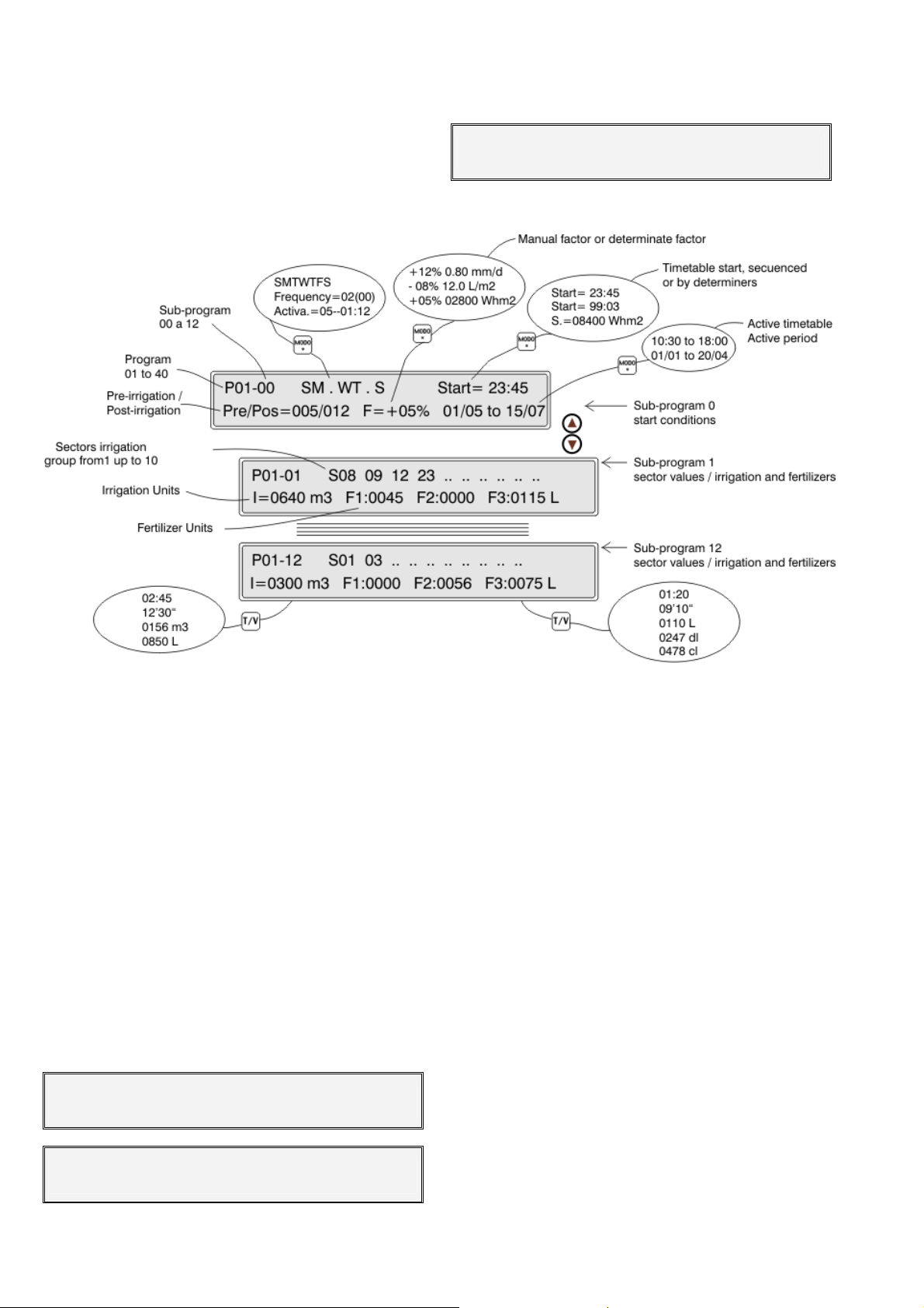
30
7. PROGRAMS
To accede to the irrigation programming press
the “FUN” (functions) key, choose number 1and then
press "Enter".
Look at an example of a program resume:
Programs : 1 Readings : 2 Erasure: 3
Parameters: 4 Manual : 5 Clock : 6
The Agrónic 4000 has 40 independent programs
with 12 sub-programs or irrigation sequences at each
of them.
The number next to the P, at the left of the upper
line of the screen, indicates the number of program.
The number of the sub-program is indicated after a
hyphen.
When 00 is set at the sub-program number it will
correspond to the program starting conditions (P01-
00).
The value P01-01 would be the first sub-program
to enter when the irrigation program started and the
P01-12 would be the last one. In necessary programs
can be enchained forming sequences of 24, 36, 48,
etc.
Inside the sub-programs there can be some
empty ones or irrigation units without value. They will
be automatically passed over when dealing with the
irrigation sequence.
Example of an irrigation program:
P01-00 SMTWTFS Start = 15:10
Pre/Post = 010/030 F=+04% 00/00 to 00/00
P01-01 S33 05 .. .. .. .. .. .. .. ..
I 02:17 F1 0023 F2 0108 L
The values of a program are the next:
On the first screen at the upper line there is the
program number and the sub-program P01-00
number. Being the sub-program 0, the values of this
screen correspond to starting conditions.
At the middle of the line, as an standard, the
days of the week when it will work are shown. In
order to discharge or dismiss a day, press the keys
marked with the days of the week (the daily key activates and deactivates all the days).
With the cursor at this position and pressing the
“MODE” key, we will cancel the activation by days of
the week and it will pass to work by “frequency” of
days. The entered value corresponds to the days it
will take between one irrigation and another. 1 would
be a daily irrigation, 2 for alternative days and 3 for an
irrigation every 3 days, etc.
The value at the right which is in brackets corresponds to the days real counter: when it arrives at 0
is when the program can work. It has to be taken into
account that this value in brackets works automatically when arriving at 0 and when the days changes it
takes the value of the days it will be without irrigating.
Examples:
Frequency: 01(00) every day.
02(00) every two days, irrigating today.
02(01) every two days, irrigating tomorrow.
05(04) every 5 days, it will be 4 days
without irrigating.
Page 31

31
In order to postpone the irrigation some days, a
variation would , for example, irrigate in alternate days
but waiting initially 8 days: “Frequency02(08)”, once 8
days have been taken away, the counter will take the
programmed ones.
Another irrigation modality would be pressing the
“MODE” key in order to work by daily activations. At
this modality the irrigation is carried out every day,
having the possibility to make several daily activations,
separated by a time to be determined by hours and
minutes. The first activation will take place at the programmed starting time.
P01-00 SMTWTFS Start = 15:10
P01-00 Frequency = 03(01) Start = 15:10
P01-00 Activa.=05—01:30 Start = 15:10
The “Start” value corresponds to the time the
program will be activated. The timetable format is
from 00:00 to 23:59 hours. The time 00:00 is not valid.
Because of this reason the program will not work by
temporization.
There are some variations for the starting which
are the next:
• The program can be started when another ends.
This programs enchainment is done by pro-
gramming at the starting time the value 99 (as the
enchainment code) and at the minutes the num-
ber of the program which precedes it. According
to this, as each program can deal with an irriga-
tion sequence of 12 sub-programs, when en-
chaining them will increase to 24, 36, 48, etc. If
the preceding program has various activations, it
will enchain at each one of them. Besides this the
first program moves the manual factor and the
determiners to the following programs.
P03-00 Start = 99:02
• The program can be started by an element
(thermostat, level, etc.) connected to a digital in-
put with starting functions. To do so, it is neces-
sary to configure a determiner at program pa-
rameters [sector 6.7.]. The Agrónic 4000 allows to
work the 4,5 and 6 base determiners, thanks to
the fact of being already discharged. For the rest
of determiners it is necessary to activate the de-
terminers options.
• Having the determiners function installed the irri-
gation can be started when a sensor value (soil-
moisture, temperature, etc.) reaches a determi-
nate level. It is necessary to configure a type 1 or
2 determiner at program parameters [sector
6.7.]. In order to program the reference value to
set on the starting, the “MODE” key has to be
pressed when the cursor is at the start value.
P03-00 SMTWTFS Start = 083.5 cbar
• Having the determiners option installed, an irriga-
tion by integration of a sensor (solar radiation
normally) in relation to the time lasted since the
previous irrigation can be started. It is necessary
to configure a type 3 determiner at program parameters [sector 6.7.]. In order to program the
reference value to set on the starting, the
“MODE” key has to be pressed when the cursor
is at the start value. At the program view [sector
12.2] the integration which is being accumulated
at each moment can be seen. Each time an irrigation takes place, the total by integration goes to
0.
P03-00 SMTWTFS S.= 07300 Whm2
In the second line of the starting conditions
screen, the pre-irrigation and the post-irrigation
which will work is requested for each one of the subprograms.
The units that here have been programmed will
be discounted when irrigating in relation to the irrigation units of each sub-program, in order to regulate
the application of the fertilizers to the irrigation water.
The fertilization will always start when the preirrigation ends, finishing when the time or volume of
programmed fertilizer ends, but, avoiding always the
application of fertilizers during the post-irrigation units.
The following value is the irrigation manual fac-
tor (F=+00%), with which we can modify in more or
less, the irrigation values of all the sub-programs by
modifying only this value.
This value is calculated each time a sub-program
starts the irrigation. With the +00% value the same
units are maintained.
P01-00 SMTWTFS Start = 15:10
Pre/Post = 010/030 F=+04% 00/00 to 00/00
Having the determiners option the fertigation can
be modified by the climatic factors, once configured at
program parameters [section 6.7].
In order to program the determiners factor, the
“MODE” key has to be pressed when the cursor is
placed at the “manual factor”, and give a pulse for
each configured determiner. In order to give room to
the factor and to the determiner reference value, the
text “Pre/Post” disappears and these units are moved
to the left.
Page 32
32
010/030 F=+07% 0.75 mm/d 00/00 to 00/00
The values of a sub-program are the following:
Look at examples of determiners:
o F=+07% 0.75 mm/d, increase the irriga-
tion a 7 % per each 0.75 millimeters/day
of crop evapotranspiration.
o F=-05% 02300 Wh/m2, diminish the fertil-
izer a 5% per each 2300 watts of solar
radiation accumulated since the previous
irrigation.
o F= -15% 05.0 L/m2, reduce the irrigation
units in relation to a 15% per each 5 liters
of rain.
For each one of the previous examples have to
be taken into account the rest of the values that affect
the determiners, to do so, look at the program parameters section [6.7.].
The last values correspond to the operation ac-
tive period of the program, with the format from
day/month to day/month. Setting all the values at 0 it
would work the whole year. It allows values which go
from a year to another (example 01/11 to 15/03).
Pre/Post = 010/030 F=+04% 01/06 to 15/07
P01-01 S33 05 .. .. .. .. .. .. .. ..
I02:17 F1 0023 F2 0108 L
-- -- -- -- -- -- -- -- -- -- -- -- -- -- -- --
-- -- -- -- -- -- -- -- -- -- -- -- -- -- -- --
P01-12 S02 04 .. .. .. .. .. .. .. ..
I01:08 F1 0017 F2 0083 L
At the first line the sector or sectors to be acti-
vated are asked. Each sub-program has the possibility
to accept up to a maximum of 10 sectors or irrigation
valves.
At the second line the irrigation (I01:08) and fer-
tilization (F2 0083 L) units that will be applied to the
previously programmed sectors are asked. If the configured fertilizers number to be used is higher than 4, it
will show from the fifth on onwards on the following
screen.
P01-01 S33 05 .. .. .. .. .. .. .. ..
I02:17 F1 0023 F2 0108 F3 0000 F4 0038 L
P01-01 S33 05 .. .. .. .. .. .. .. ..
I02:17 F5 0000 F6 0009 L
When pressing the “MODE” key when the cursor
is placed at the active period units, it will show the
active period values. Its function is to limit the determiners which start the irrigation to do it only at the
here marked timetable.
All the values that go from the end of one day to
the beginning of the next day are accepted (example:
22:45 a 06:00).
Pre/Post = 010/030 F=+04% 10:00 a 18:30
The start by temporization or manual is not limited by the active timetable.
When a program is operated by activations, it has
to be taken into account that the ones which are left to
do will be cancelled when the program is left out of
the active timetable. In the “installation configuration”
it can be configured so that they are not cancelled.
Each program is formed by 12 sub-programs. If it
is not necessary to do an irrigation sequence, only the
first program will be given values. On the other hand, if
some sectors have to be automatically activated when
other end, values will be given to the following subprograms. If a sub-program has not got irrigation sectors programmed or the irrigation value is “0” it will be
omitted in the sequence.
The type of units will be configured at the pa-
rameters sector but at any sub-program they can be
modified by using the T/V key, both for the irrigation or
for the fertilization. To do so, press the key when the
cursor is placed at the value to be modified. It is possible to work with different units between subprograms.
• Time = 00:00 (hours : minutes).
• Time = 00’ 00” (minutes seconds)
• Volume = 0000 m
3
(in irrigation)
• Volume = 0000 L (in irrigation and fertilization)
• Volume = 0000 dl (in fertilization)
• Volume = 0000 cl (in fertilization)
The pre-irrigation and the post-irrigation take the
same values each sub-program has.
The way of applying the fertilizers will depend on
what programmed at the Parameters sectors, having
the possibility to be “in series” (one after the other),
parallel (all at a time) and for both types with proportional or not application.
In the event of series fertilization, when several
programs are operating at the same time and have
different fertilizers assigned, the fertilizers will be injected simultaneously. Thus, series fertilization may
give way to 8 fertilizers being injected in 8 different
programs.
Page 33
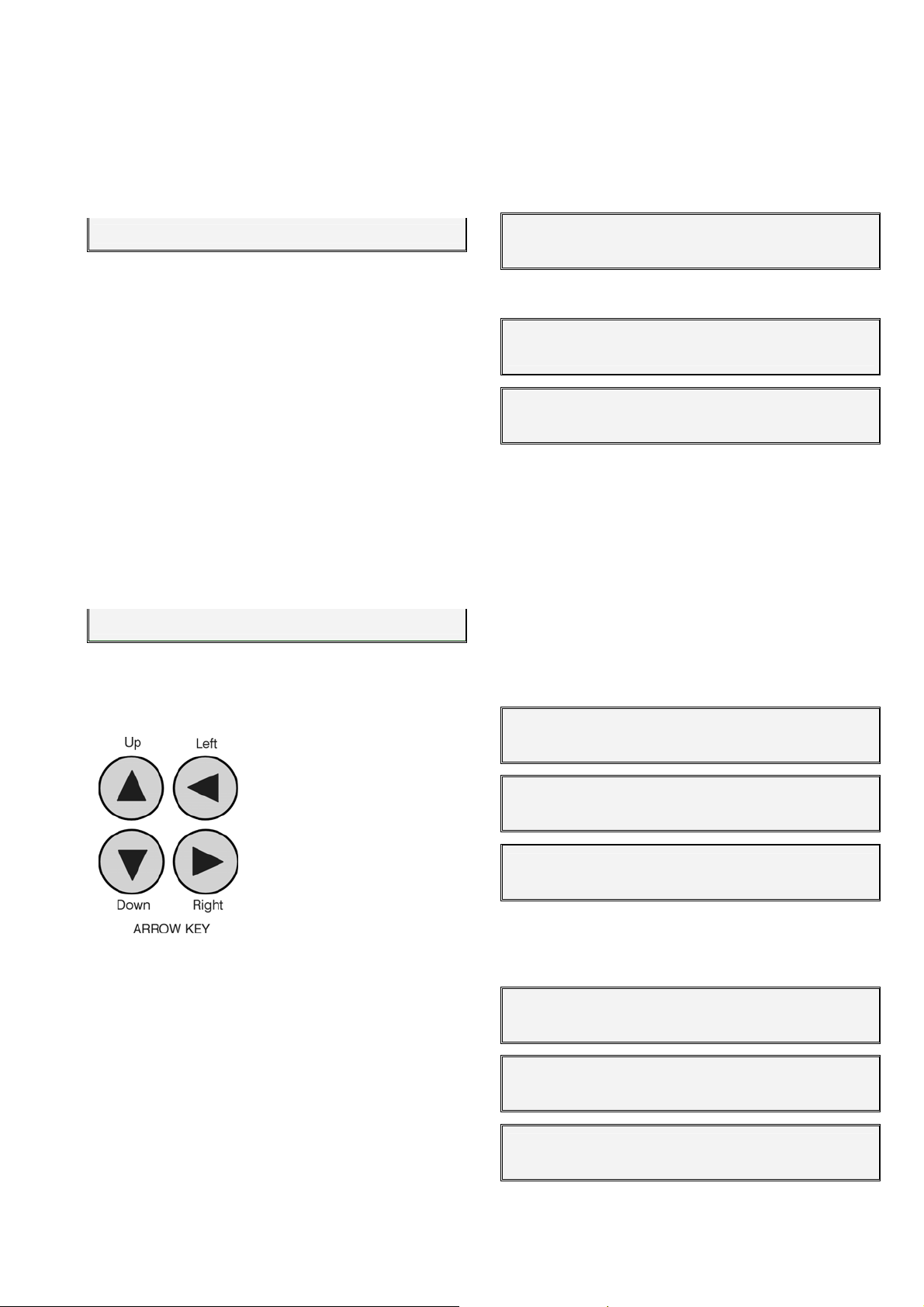
33
If a “in series” and “proportional” application is
programmed, the proportion is configured in parameters of fertilizers for each one of them, but, if the ap-
plication is “parallel” and “proportional” it is programmed in each one of the sub-programs, as can be
seen in the last line of this example screen:
I0185 m3 F1 10/03 F2 08/13
According to this, each fertilizer has two values,
an irrigation units one at the left of the bar, and a fertilizer one at the right of it.
If operation at both values by volume, the previous example would be: per each 10 m
3
of water, 3
liters, deciliters or centiliters of “fertilizer 1”, and for the
second 13 liters, deciliters or centiliters of “fertilizer 2”
per each 8 m
3
of water. At “flow-parameters” the units
these proportions will be used with are identified.
The irrigation units of the ratio are in time or volume, always depending on the irrigation units configured in “Parameters - Volumes“ [6.5.]. The irrigation
units can be modified with the key “T/V" for each program. This way, combinations may be used, for example irrigation for 2 hours and injection 3 liters of
fertilizer per 10 m
3
of irrigation.
I02:00 F1 10/03 F2 08/13
In this way of operation a total value of fertilizer to
be applied is not given but it is continuously relates to
the irrigation quantity programmed.
To move to another program the cursor has to be
placed at the program number
(P01) and enter the new one
by using the up arrow key to
increase and the down one to
decrease.
In order to accede to a
sub-program the cursor has to
be placed at the (P01-00)
value and enter the new one.
Another possibility is by using the arrows from here or
from the different values of the sub-program; use the
up arrow to increase and the down one to decrease.
The right-left arrow keys are used to move the
cursor between the different values.
To exit any programs screen, press the “Func-
tion” or “View” keys.
8. READINGS
The READINGS function will be used whenever
we want to consult statistical data. To do so, press the
“FUN” key, choose the function by its number (2) and
then press “Enter”.
Programs : 1 Readings : 2 Erasure : 3
Parameters: 4 Manual
The “Readings” menu is the following:
READINGS Totals: 1 Anomalies : 2
New anomalies : 3 History: 4 Sensors : 5
READINGS Agr. Radio 868: 6 Agr.Rad24 :7
Ag.Monocable : 8
In order to exit any reading screen press the
“Function” or “View” keys.
8.1. TOTALS READINGS
At the "Totals" the water and fertilizers units applied by time and volume are shown, in general and in
each sector.
The first screen of "General totals” informs of the
date and time when the last erasure of totals was carried out, the time and total volume of irrigation and the
time or total volume of each fertilizer.
General totals 15/07/02 17:47.11
Irrigation = 0000:00.00 000000.000 m3
General totals F1 000000.00 L
F2 000000.00 L F3 000000.00 L F4 000000.00 L
General totals F5 0000:00.00
F6 0000:00.00 F7 0000:00.00 F8 0000:00.00
All the other totals screens correspond to the values of the 99 sectors which can be found in the
Agrónic 4000.
Sector totals 01 000.00 m3/h
Irrigation = 0000:00.00 000000.000 m3
Sector totals 01 F1 000000.00 L
F2 000000.00 L F3 000000.00 L F4 000000.00 L
Sector totals 01 F5 0000:00.00
F6 0000:00.00 F7 0000:00.00 F8 0000:00.00
: 5 Clock : 6
Page 34

34
In the irrigation units, the time format is hours,
minutes and seconds, and the volume is cubic meters
with three decimals. In fertilizer there is only one format depending on the time or volume units assigned
to the fertilization at” flow parameters” [6.5.]. If the
irrigation units of a program are different, they will not
be added. That is why it is very important to take into
account that in order to do a correct addition of the
applied fertilizers, it is necessary to work with the
same units both at flow parameters and at programs.
The totals by volume of the sectors that are irrigating at the same time with the same counter, it will
be done distributing the value of each pulse of the
counter, depending on the expected flow in each sector. This detail is configured at the “ParametersSectors” section [6.6.]. Look at the example below:
Sector 1, expected flow = 23.6 m3/h
Sector 2, expected flow = 18.9 m
3
/h
A pulse of the 1000 liters volumetric counters arrives, at the totals 555.294 liters will be
distributed to sector 1 and 444.706 liters to sector 2.
8.2. ANOMALIES READINGS
The anomalies are incidences that are recorded
in the memory and which can be read at the ”Anoma-
lies-Reading” section. In case that since the previous
reading a new reading has been carried out, we will
read them at the previous section and besides this,
filtered at the “New Anomalies –Readings”
The anomalies are a part of the general record
which is recorded in the memory. The anomalies and
any event the controller has done are recorded in it; all
the other records can only be seen from a PC when
the link to a PC option is installed. It has a 5000 records capacity. When they are filled, the oldest ones
start to be erased.
Each anomaly has the date and time when it
happened and a descriptive text with the values that
affect it.
With the up arrow key a previous anomaly can be
seen and with the down arrow a posterior one..
Description of each type of anomalies:
Each one of the different anomalies can activate
an output alarm, and, with the option activated, an
SMS message. From the installer configuration, which
anomalies activate the alarm and which ones send a
message can be modified. A configuration is provided
with the unit; in the following description the following
symbols will appear in order to indicate which of them
activate alarms and/or send messages.
[AL-G] = It activates the general alarm.
[AL-F] = Activation of a fertilizer alarm.
[MSG] = It sends an SMS message to a mobile.
• Power cut. [ - ] [ - ]
When there is a power cut longer than 1 minute
and shorter than 24 hours it records the date and the
time when the cut began and when it finished.
• General Malfunction. [AL-G] [MSG]
It is produced when the safety factor of the installation of irrigation connected to the input of general
malfunction activates and produces a definitive stop of
the controller. To cancel the definitive stop enter in
“Function–Manual–Malfunctions”, being reactivated
the programming which is being carried out at the
same point where it stopped.
• Flow Anomaly. [AL-G] [MSG]
In te flow control of the irrigation counters, an
anomaly is produced by defect or excess of the expected flow, indicating the meter and value of the flow.
• Irrigation counter malfunction. [AL-G] [MSG]
When an irrigation volumetric counter fails and
does not emit pulses, after some temporization, (if
nothing is indicated 10’), it goes into anomaly and
causes a definitive stop of the controller. Once repaired, enter in “Function–Manual–Malfunctions” to
reactivate at the same point where it stopped.
• No control fertilizer malfunction. [AL-F] [MSG]
When more than 15 pulses of a fertilizer counter
are received during a time (if nothing is indicated 10’)
and there is no order to inject fertilizer, it goes into
anomaly and causes a definitive stop of the controller.
Once repaired, enter in “Function–Manual–Malfunctions” to reactivate at the same point where it
stopped.
• Fertilizer counter anomaly. [AL-F] [MSG]
When a volumetric counter of fertilizer fails and
does not emit pulses, after some temporization (if
nothing is indicated 10’), it goes into an anomaly and
causes a temporary stop of the fertilizer in the program being carried out (the rest of the fertilizers continue); in a new irrigation start with fertilizer it will try it
again.
• Excess of fertilizer anomaly. [AL-F] [MSG]
In an irrigation with fertilization and a postirrigation programmed, it can be that the irrigation
units arrive at the post-irrigation and the fertilizer is still
left to inject, it will stop then to inject it and it will keep
the anomaly with the exceeding units of the different
fertilizers. It also goes into anomaly when eventually
finishes an irrigation with fertilizers.
When more than four fertilizers are configured,
two different anomalies will take place, one for the first
four and one for the others.
• Proportional fertilization anomaly. [AL-F] [MSG]
In the application of fertilizer proportional to the irrigation, it goes into anomaly and the program which
is being carried out stops the fertilization when, after
Page 35
35
three consecutive times the irrigation units of the proportion finish before the fertilizers ones.
• No control filters cleaning anomaly. [AL-G] [MSG]
When one cleaning after another is completed in
a number configured at “Parameters-Filters” [6.2.], it is
an anomaly and stops cleaning until it is restarted at
“Function–Manual–Malfunctions”.
• Intrusion alarm anomaly. [AL-G] [MSG]
An intrusion has been detected at the installation.
• Error in memory anomaly. [AL-G] [MSG]
When an erroneous value is detected in the
memory, a complete erasure is made and the anomaly is recorded (very exceptional case).
• I/O communication anomaly. [AL-G] [ - ]
When a bad control of the inputs and outputs is
detected, an anomaly is registered (very exceptional
case).
• Temporary stop anomaly. [ - ] [ - ]
The security element of the installation connected
to the input detects a process which is not correct,
causing that the programs that are working with sectors assigned to the input stop and it continues with
the following ones in the sequence of irrigation.
• Conditional stop anomaly. [ - ] [ - ]
It informs of the conditional stop of a program by
an input with a sensor element connected. When the
sensor ends, its action will restart the irrigation.
• Definitive stop anomaly. [AL-G] [MSG]
An element of safety of the installation activates
the input, all sectors assigned to the input will stop
definitively until it is not finished at “Function–Manual–
Malfunctions”.
[ anomalies for DIESEL Control option ]
• A. do not carry out starting. There is pressure.
[AL-G] [MSG]
• Starting anomaly. [AL-G] [MSG]
• Oil pressure anomaly. [AL-G] [MSG]
[ anomalies for pH / EC Control option ]
• pH alarm anomaly. [AL-A] [MSG]
• 100 % pH injection anomaly. [AL-A] [MSG]
• EC alarm anomaly. [AL-F] [MSG]
[ anomalies for Communication options ]
• Microisis communication a. [AL-G] [ - ]
• µMetos communication a. [AL-G] [ - ]
• Radio communication a. [AL-G] [ MSG]
• Agrónic Radio Collision a. [ - ] [ - ]
• Agrónic Radio battery level a. [AL-G] [ - ]
• Monocable communication a. [AL-G] [MSG]
• Exp modules communication a. [AL-G] [ - ]
• SMS messages communication a. [AL-G] [ - ]
8.3. HISTORY READINGS
The Agrónic 4000 records, independently of the
current day and the last 29 days, the starts each
program has made, the number of filter cleanings, the
rain, the integration of radiation and day temperature,
besides this, for each one of the 99 sectors, the total
units accumulated in the irrigation day and fertilizer in
addition to the pH and EC averages.
When entering at the record, it will do it in the current day. To move in between the days use the right
arrow key for the day before and the right one for the
next day. To move in between the values of one day,
use the up and down arrow keys.
On the first four screens it shows the starts each
program has carried out during the whole day.
23/07 P= 01 02 03 04 05 06 07 08 09 10
Starts = 03 00 00 00 01 00 00 02 00 00
In another screen it shows the filter cleanings carried out by each group and besides this, whether
some sensors are connected or not, the day integration by solar radiation, the temperature, the
evapotranspiration and the integration by temperature.
23/07 L. Filters = 005 002
07318 Whm2 00.5 l/m2 0.08 mmd 0435 ºC*h
On the following screens it shows for each sector,
the total of the day in irrigation, the pH and EC average (in case that sensors are connected) and the fertilizers totals.
23/07 S01 I= 0000:00 00.0 pH 0.0 mS
F1 0000’00” F2 0000’00”
The irrigation units of each sector will be in time
or volume depending on the units of the first irrigation
of the day of each sector. The fertilizer units will depend on the habitual ones configured at the flow parameters.
The pH and EC average is carried out by taking
readings every second in the irrigation temporization
of each sector.
The record values can not be modified nor
erased.
The first 20 sensors function have the average recorded every 30 minutes of the day in each one of the
record days. These values can only be seen from the
PC link option.
Page 36

36
8.4. SENSORS READINGS
In case the Agrónic 4000 had a sensor connected
in order to measure climatic values that affect the crop
or the installation, they can be read in this section,
with a screen per sensor.
Among the 76 possible, the number of sensor is
shown in the first line, and at its right the instant value
with the sensor units. Where the sensor is connected
to is shown in the second line.
Sensor 01 0642 Wm2
Input: 04 at the base
Use the up and down arrow keys to move among
the sensors; press “Function” or “View” to exit.
8.5. AGRÓNIC RADIO 868 READINGS
When the Agrónic 4000 is supplied with the Via
Radio option, in section 6 of the readings you may
consult the status of the different parameters of the
different Radio Modules connected to the Agrónic.
If the model is the Agrónic Radio 868 the following reading display appears:
Radio module 01 ED : 00100010 SR : 00010010
Bat. level: *02, rssi: *20 (1 1 0 1) 48
The module number that refers to the screen is
indicated on the first line of the screen. The status of
the Digital Inputs (ED) and the Relay Outputs (SR) are
also indicated. A “1” means that they are activated.
The second line indicates the battery level, which
may be from 0 to 7. In the rssi section, the first two
numbers indicate the reception level detected by the
Radio Module, and the last two numbers indicate the
reception level detected by the link CER. The 4 numbers in parenthesis indicate the status of the last 4
communications. A “1” means that they have been
performed satisfactorily.
The symbol “*” next to the value of the reception
or battery levels indicates that the value is insufficient
to assure proper functioning. In reception levels it will
be below 35, and the battery level below 4.
If the model is the Agrónic Radio 868-16, the
status of the communication with the EAR, the channel
used, the communication protocol and the version of
the EAR program are displayed on the first screen:
MAR01 Active: yes Com.: 1111111111111111
rssi EAR: 50 rssi MAR: 50 battery: 3.6V
The status of the last 16 receptions is shown on
the screen. The level of radio reception (rssi) in the
EAR and the MAR (communication is critical when it is
below 35). The battery level (should be change when
it is below 3.3V).
8.6. AGRÓNIC RADIO 2.4 READINGS
When the Agrónic 4000 has the Via Radio option,
in section number 7 of Readings the status of the
Modules Agrónic Radio 2,4 which are connected to
the Agrónic 4000 may be consulted.
The status of the Communication with the EAR,
the channel used, and the version of the EAR program
will appear on the first screen.
Agr.Radio 2,4 Channel: 1
1.00 Active: yes Communicating: yes
The following screens display the status of Communication with each of the MAR:
MAR001 Active: yes Com.: 1111111111111111
rssi EAR: 50 rssi MAR: 50 battery: 4.1V
The status of the last 16 receptions is shown on
the screen. The level of radio reception (rssi) in the
EAR and the MAR (Communication is critical when it is
below 35). The battery level (should be change when
it is below 3.4V).
8.7. AGRÓNIC MONOCABLE READINGS
When the Agrónic 4000 has the single cable option, section 7 of Readings may be consulted for the
status of communication with the modules; and, in the
first screen, the status of the communication with the
EAM and it version of program.
Agr.Rad. Channel: 1 Protocol: 1
1.01 Active: yes Communicating: yes
The following screens shows the status of com-
munication with each of the MAR.
Page 37
37
9. ERASURE
The ERASURE function will be used to cancel the
programming or the totals values. To do so, press the
“FUN” (functions) key, choose the function by its
number (3) and then press “Enter”.
Programs : 1 Readings: 2 Erasure : 3
Parameters: 4 Manual : 5 Clock : 6
The “Erasure” menu is the following:
ERASURE Programs : 1 All : 2
Totals : 3
To exit any erasure screen press the “function” or
“View” keys.
Care has to be taken when using this function,
yet important values for the irrigation system working
can be cancelled.
At sector “1” the program number to be erased
will be asked, at sector “2” to erase the whole programs and at number “3” to erase all the totals. Confirmation of the erasure will always be requested.
Are you sure to erase? : NO
10.
MANUAL
By using the manual function, the following can
be done:
Start the beginning of a program.
Stop a program that is irrigating.
Leave a program out of service; the values of the
irrigation which is taking place will be erased.
Remove a program from the out of service position.
Stop the system, that it can also be done with the
STOP key. The programs are postponed and the
outputs deactivated.
Stop the out of service, that can also be done with
the STOP key. The programs will reinitiate at the
same place where they stopped.
Set the Agrónic at out of general service, leaving
everything stopped and erasure the values of the
irrigations that are taking place out of the programs.
Exit the out of service.
Start the filter cleaning.
Finish the filter cleaning.
Finish the stop by general malfunction.
Finish the stop by flow malfunction.
Finish the stop by counter malfunction.
Finish the stop by fertilizer without control.
Finish the definitive stop of the sectors.
Reinitiate the injection by error in the fertilizers pro-
portions.
Finish the stop of the filters by filter out of control
malfunction.
Finish the activation of the general alarm outputs,
fertilizer or acid.
Finish the stop of the alarm by EC.
Finish the stop of the injection by pH alarm.
To do so, press the “FUN” key, choose the option
by its number (5) and then press “Enter”.
Programs : 1 Readings : 2 Erasure : 3
Parameters: 4 Manual : 5 Clock : 6
The “Manual” menu is the following:
MANUAL Out of service : 1 STOP : 2
Programs : 3 Malfunctions : 4 Filters : 5
MANUAL Outputs : 6
To exit any manual screen press the “Function”
or “View” keys.
It is possible to move to another screen from the
“Out of service” sector in order to do a general or a
program one.
Page 38

38
General : 1 Program : 2
Out of general service (Y/N) : NO
Before the out of service is carried out, the confirmation will be asked, yet once it is done the values
of the irrigation that is taking place are cancelled from
the program which is being carried out or from all of
them, at the general. It can be of use when the irrigation of all the programs that are taking place it wants
to be cancelled. This can be done by entering for a
while at the general out of service and leaving afterwards.
The “STOP” can be done from here or through
the key. The functions and the unit outputs are
stopped then, being reactivated at the same point
when the Stop ends. While it is stopped, the programs
continue starting but the leave at stand by, besides
this, the keyboard beeper emits an advice beep every
ten seconds.
At the “Programs” manual action, an irrigation
programming can be started at any sub-program; on
the other hand, if the program has already started it
will be possible to finish it.
The number of program and sub-program will be
asked at first, and then, the confirmation in order to
stop or finish.
11. CLOCK
The CLOCK function will be used to set on the internal clock of the Agrónic 4000. To do so, press the
“FUN” key, choose the function by its number (6) and
then press “Enter”.
Programs : 1 Readings: 2 Erasure : 3
Parameters: 4 Manual : 5 Clock : 6
Enter the day of the week, day of the month, the
month, the last two digits of the year, the hour, the
minutes and the seconds according to this order.
When pressing “Enter” at the seconds the clock is up
dated.
Wednesday 17/08/02 20:06.33
Program number : 05-01
Start (Y/N) : YES
The “Malfunctions” sector is used to finish, once
repaired and according to the user, any anomaly. At
most of the cases the irrigation is restarted at the
same point it stopped.
At “Filters” a cleaning or backflushing can be
started or stopped.
When entering at the option “6” “Outputs” of the
menu, the following screen appears, where it is possible to directly activate the relay outputs. Care has to
be extremely taken yet no kind of control exists and
damages can be caused to the installation (securities
are no taken into account). This function is only of
use, for the installer, when setting all the elements.
To exit the screen, the 8 possible outputs have to
be at 0, it means, deactivated.
At the “outputs connection” [4.3.4.] there is a
chart with the relays situation. We recommend consulting it.
Page 39
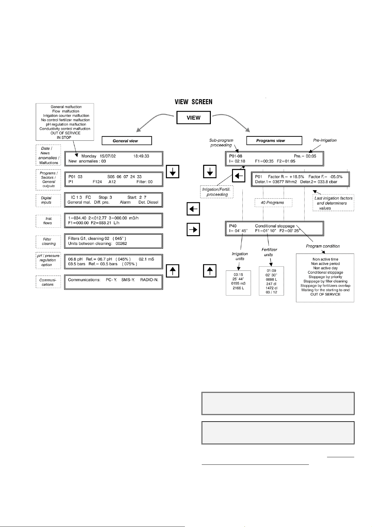
12.
VIEW
To go into this section press the “View” key. We
will find detailed information about what the controller
is doing.->
Look at the resume:
39
-> There is a “General view” and a “Programs
view”. To move in between the view screens use the
up and down arrow keys. To move from a general
view to a programs one or to do the opposite, use the
right and left arrow keys.
The last visited programs and general view
screen is always recorded. This is why when coming
from “Functions” or “View” it will show again the last
screen seen when exiting the “View”.
When a “View” automatically enters after a power
cut, it is done through the first screen of the general
view.
12.1. GENERAL VIEW
The general view is formed by a series of screens
with resumed information of the system general operation.
The first screen shows the clock information
from the seconds to the year.
The second line usually informs about the new
anomalies which have taken place since the previous
reading, in the same line it also informs if there are
some program out of service. When a malfunction or a
manual action of the next list which is shown at following takes place, it will be shown intermittently in the
second line until the user repairs the anomaly or/and
knows it by canceling it at “Function–Manual–
Malfunctions” [10].:
o General malfunction
o Flow malfunction
o Irrigation counter malfunction
o Fertilizer without control malfunction
o pH regulation malfunction
o Conductivity control malfunction
o Out of service
o At STOP
Monday 12/07/02 18:49.33
New anomalies : 03 Pro. OUT OF SERVICE
Monday 12/07/02 18:49.33
Flow malfunction
The second screen inform about the programs
and sectors operating at that moment, all these in the
first line. If more than four programs are activated at a
time, it will be intermittently shown in groups of four.
Page 40
40
The same occurs with the sectors when more than 8
are activated at a time.
In the lower one it shows the outputs activated,
starting by the pumps (M1234), fertilizers (F12345678
LF), mixers (A12345678) and the filters.
P01 03 S05 06 07 24 33
M1 F124 A12 Filter: 00
The third screen indicates the digital functions
activated, whenever they have been configured. The
first ones to be shown at the first line are the irrigation
counters ones (IC1234), the fertilizers counters
(FC12345678), the stop functions (Stop:1234), the
program start ones (Start:12345678) and at the second line, the general malfunction function (Gen. Fai.),
the filters differential pressure gauges (Pre. Dif. 1234),
the intrusion alarm one (Alarm) and the diesel detector
one (D. Diesel).
IC1 3 FC Stop: 3 Start: 2 7
Av. Gen. Pre. Dif. 2 Alarm
If volumetric counters for the irrigation or fertilization are set in the installation, it will be explained on
the fourth screen of the instantaneous flows.
In the first line it shows the irrigation flows. Besides this, if flow control is ordered it can show the
“>” of major or the “<” of minor after the irrigation
counter number, when the instantaneous flow is going
out of the margins. The maximum value that can be
displayed on screen in each format is 650.00 or
6500.0 m
3
/h
The second line is for the fertilizers instantaneous
flow. When more than four are configured, they will be
shown intermittently in two groups. The maximum
value that can be displayed on screen is 650.00 or
6500.0 L/h
1=034.40 2<012.77 3=000.00 m3/h
F1=000.00 F2=033.21 L/h
When filters cleaning group has been configured,
it will show a screen per group with the information of
the filter which is doing the cleaning and the irrigation
units (minutes or m
3
) missing for the following clean-
ing.
Filters G1, Cleaning the 02 (045”)
Units between cleanings: 0262
If a pressure or pH regulation option is installed,
we will see in the first line of the screen the instantaneous value of the pH sensor, at its right the reference
requested for the irrigation that is taking place at that
moment, in brackets the injection percentage and
finally, the conductivity sensor value (EC).
In the second line the values correspondent to
the pressure regulation, with the pressure sensor
value, the reference and the injection %.
06.8 pH Ref. = 06.7 pH (045%) 02.1 mS
03.5 bars Ref. = 03.5 bars (075%)
On the last view screen, it informs about which
elements extern to the controller there is communication established with.
Communications: PC-yes SMS-yes RADIO-no
Microisis-yes METOS-yes MONOCABLE-yes
12.2. PROGRAMS VIEW
For each one of the 40 programs, there is an informative screen of the program condition. If it is irrigating it will show in the first line next to the program
number the number of the sub-program that is proceeding, next, if some determiners are set for the program it will be shown by the following texts:
o Non active time
o Non active period
o Non active day
o Conditional stop
o Stop by priority
o Stop by filter cleaning
o Stop by filters overlap
o Waiting for the starting to end
o OUT OF SERVICE
When the irrigation is ordered by pressing at several activations, it will show the left ones and the time
missing for the next one:
o Activations: 03 01:20
Later, if there is a pre-irrigation proceeding in that
moment, it will inform of the units missing to reinitiate
the fertilization.
In the second line, when irrigating, there will be
the units of irrigation and fertilizer
applied.
P01-08 Pre.= 00:05
I= 02:18 F1=00:35 F2=01:05
The irrigation units format can vary depending on
the following list:
o Hours and minutes, 00:00
o Minutes and seconds, 00’00”
o Volume in cubic meters , 0000 m3
o Volume in liters, 0000 L
The fertilizer units one is:
o Hours and minutes, 00:00
o Minutes and seconds, 00’00”
o Volume in liters, 0000 L
o Volume in deciliters, 0000 dl
o Volume in centiliters, 0000 cl
still missing to be
Page 41

41
When the fertilization is proportional the format is
“00/00”, in this way, each fertilizer has two values, an
irrigation units one at the left of the bar and the fertilizer one at the right of the bar.
When a program has been configured to work by
determiners
and the option is installed, further information related to the determiners is shown in another
screen: press the right and left arrow keys to go into
that screen.
On the first line, next to the program number is
indicated the “irrigation” factor that was applied in the
last irrigation and to its right the “fertilizing factor”; in
the event that there is more than one determiner to be
modified, for example, the irrigation, it will be per-
NOTES:
formed applying the sum of the factors with its respective signs, the result is what we see on this consultation screen.
The values of the second line depend on the type
of determiner of the program, in which it is initiated or
in those that modify the irrigation / fertilizer, it will show
the accumulated / integrated units from the previous
irrigation; in those modifying the value ratio of a sensor (Eto, ground moisture, etc.) they show the instantaneous value of the sensor by the crop constant.
P01 Factor I.= +18.5% Factor F.= -05.0%
Condi. 1= 03677 Wh/m2 Condi. 2 = 03.1 l/m2
Page 42
p
42
General malfunction
Flow malfunction
Irrigation counter malfunction
No control fertilizer malfunction
pH regulation malfunction
Conductivity control malfunction
OUT OF SERVICE
IN STOP
Date /
New Anoma-
lies / Mal-
functions
Monday 12/07/02 18:49.33
New anomalies : 03
General View
VIEW SCREENS
VIEW
Sub-program
View Programs
proceeding
P01-08 Pre.= 00:05
I= 02:18 F1=00:35 F2=01:05
Pre-irrigation
Programs /
Sectors /
General
outputs
Digital
inputs
Instantane-
Flows
ous
Filter
cleaning
pH / pressure
regulation
option
Communications
P01 03 S05 06 07 24 33
M1 F124 A12 Filter: 00
IC 1 3 FC Stop: 3 Start: 2 7
Gen. Fai. Dif. Pre. Alarm Det. Diesel
1=034.40 2<012.77 3=000.00 m3/h
F1=000.00 F2=033.21 L/h
Filters G1, cleaning the 02 ( 045” )
Units between cleanings: 00262
06.8 pH Ref.= 06.7 pH ( 045% ) 02.1 mS
03.5 bars Ref.= 03.5 bars ( 075% )
Communications: PC-yes SMS-yes RADIO-no
P01 Factor R.= +18.5% Factor F.= -05.0%
Deter.1= 03677 Whm
2
Deter.2= 03.1 l/m
2
Irrig. and ferti.
roceeding
40 Programs
Last irrigation
factors and deter-
miners values
P40 Conditional Stop
I= 04’ 45” F1=01’ 10” F2=00’ 25”
Irrigation
Fertilizer units
Program conditions
units
Non active timetable
03:15
25’ 44”
0195 m
3
2166 L
01:09
02’ 30”
0098 L
0241 dl
1472 cl
03 / 12
Non active period
Non active day
Activations: 03 01:20
Conditional stop
Stop by priority
Stop by filter cleaning
Stop by filters overlap
Waiting for the starting to end
OUT OF SERVICE
Page 43
g
4
01/0
0/0
43
FUNCTIONS SCREENS
SMTWTFS
Frequency =02(00)
Activa.=05—01:12
Start= 23:45
Start= 99:03
I.=08400 Wh/m
2
P01-00 SM. TT. S Start =23:45
Pre/Pos=005/012 F=+05% 01/05 to 15/07
P01-01 S08 09 12 23 .. .. .. .. pH=06.8
R=0640 m3 F1:0045 F2:0115 L
12 Subprograms
P01-12 S01 03 .. .. .. .. .. .. pH=06.5
R=0300 m3 F1:0000 F2:0035 L
0 Programs
P40-00 Frequency=03(01) Start= 23:45
Pre/Post=005/012 F=+00% 00/00 a 00/00
10:30 to 18:00
1 to 2
FUNCTION
READING Totals : 1 Anomalies : 2
New anomalies : 3 History: 4 Sensors: 5
Programs: 1 Readings: 2 Erasure: 3
Parameters: 4 Manual: 5 Clock: 6
4
READING Agronic Radio: 6
Agronic Monocable: 7
ERASURE Program: 1 All: 2
Totals: 3
Wednesday 19/06/02 07:45.33
MANUAL Out of service: 1 STOP: 2
Pro
rams: 3 Malfunctions: 4 Filters: 5
+12% 0.8 mm/d
-08% 12.0 L/m2
+05% 02800 Wh/m
2
PARAMETERS Fertilis.: 1 Cleaning: 2
Generals: 3 Inputs: 4 Flows: 5
MANUAL Outputs: 6
PARAMETERS Sectors: 6 Programs: 7
Comunica.: 8 Miscellaneous: 9
Page 44
A
44
PARAMETERS
SCREEN
FUNCTION
Programs : 1 Readings: 2 Erasure: 3
Parameters: 4 Manual: 5 Clock: 6
PARAMETERS Fertiliza.:1 Cleaning: 2
Generals: 3 Inputs: 4 Flows: 5
PARAMETERS Sectors: 6 Programs: 7
Comunica.: 8 Miscellaneous: 9
Fertilizers parameters 1
Number of fertilizers ( 0 – 8 ): 4
Fertilization series (1) parallel (2): 2
Proportional fertilization ( Y/N ): YES
Fertilizers end cleaning: 018”
Mixer 1 Pre-mixing: 025”
Start / stop mixing: 015”/120”
Mixer 2 Pre-mixing: 025”
Start / stop mixing: 000”/001”
Mixer 3 Pre-mixing: 000”
Start / stop mixing: 000”/000”
Mixer 4 Pre-mixing: 000”
Start / stop mixing: 000”/000”
- pH CONTROL OPTION -
pH alarm= (+) 0.6 pH ( - ) 0.4 pH
Detection delay: 038”
Detection delay alarm 100%: 025”
EC Alarm = (+) 02.1 mS ( - ) 00.8 mS
Detection delay: 105”
Inject for base ( 1 ) acid ( 2 ): 2
Modulation cycle: 2.5”
Proportional band: 2.0
Reaction: 1
Apply acid in pre-irrigation: NO
pply acid in post- irrigation: YES
Filter cleaning Parameters 2
Filter group number: 1
Cleaning time: 134” subg. 1: 01 to 01
Cleaning ime: 108” subg. 2: 02 to 05
Pause time between filters: 04”
Units between cleanings: 02300
Stop sectors when cleaning: Y.
Maximum num. of cleanings: 3
In relation to P 1 2 3 4 C 1 2 3 4
Y Y N N
Y N N N
Flow parameters 5
Irrigation units =
hh:mm (0) mm’ss” (1) m
3
(2) L(3): 2
Fertilization units =
hh:mm (0) mm’ss” (1) L (2) dl (3) cl (4): 2
Irrigation counter 1
Nominal flow margin high/low: 10 / 08 %
Irrigation counter 2
Nominal flow margin high/low: 12 / 12 %
Irrigation counter 3
Nominal flow margin high/low: 12 / 12 %
Irrigation counter 4
Nominal flow margin high/low: 00 / 00 %
Detection delay: 280”
Stop type, NO (0) Tem. (1) Def. (2): 1
Irrigation detection delay: 033”
General outputs parameters 3
Pump 1 Output number: 0082
On/off temporization: 005” / 018”
Pump 2 Output number: 0083
On/off temporization: 020” / 012”
Pump 3 Output number: 2201
On/off temporization: 004” / 004”
Pump 4 Output number: 0000
On/off temporization: 000” / 000”
Fertilizers F1 F2
Output number: 00000084 00000085
Fertilizers F3 F4
Output number: 00000000 00000000
Fertilizers F5 F6
Output number: 00000000 00000000
Fertilizers F7
F8
Output number: 00000000 00000000
Mixers F1 F2
Output number: 00000087 00000088
--->
--->
Mixers F2 F4
Output numbers: 00000000 00000000
Mixers F5 F6
Output numbers: 00000000 00000000
Mixers F7 F8
Output numbers: 00000000 00000000
Auxiliar Fert. F1 F2
Output numbers: 00000084 00000085
Auxiliar Fert. F3 F4
Output numbers: 00000086 00000000
Auxiliar Fert. F5 F6
Output numbers: 00000000 00000000
Auxiliar Fert. F7 F8
Output numbers: 00000000 00000000
Fertilizer general output: 0080
Fertilizer cleaning output: 0081
Filter output G1: 2161 a 2165
Filter general output G1: 0090
General alarm output: 0091
Fertilizer alarm output: 0092
Start/stop temporization alarm: 008”/030”
Normally open alarm (Y/N): NO
- pH CONTROL OPTION -
pH control general output: 0093
pH control alarm output: 0094
- DIESEL CONTROL OPTION -
Starting output: 0070
Stop output: 0071
Power output: 0072
Pre-heating output: 0000
Time of starting: 04”
Time between attempts: 015”
Time of pre-heating: 000”
Time of stop: 035”
Time between starting and pump: 150”
Time between pump end and stop.: 200”
Page 45
45
PARAMETERS SCREENS
Digital inputs parameters 4.1
Function code
Input number: 00000000
Code 01: General malfunction
-Detection delay: 030”
Code 02: Differential pressure gauge 1
Code 03: Differential pressure gauge 2
Code 04: Differential pressure gauge 3
Code 05: Differential pressure gauge 4
-Detection delay: 030”
Code 06 : Stop 1
Code 07 : Stop 2
Code 08 : Stop 3
Code 09 : Stop 4
-Detection delay: 030”
-Temporary, Conditional, Definitive
-Anomaly Y/N
Code 10: Intrusion alarm
-Detection delay: 010”
Code 11 : Irrigation counter 1, pulses
Code 12 : Irrigation counter 2, pulses
Code 13 : Irrigation counter 3, pulses
Code 14 : Irrigation counter 4, pulses
-Pulse value: 01000 L
-Max. time between pulses: 240”
Code 15 : Fert. counter 1, pulses
Code 16 : Fert. counter 2, pulses
Code 17 : Fert. counter 3, pulses
Code 18 : Fert. counter 4, pulses
Code 19 : Fert. counter 5, pulses
Code 20 : Fert. counter 6, pulses
Code 21 : Fert. counter 7, pulses
Code 22 : Fert. counter 8, pulses
-Pulse value: 0100 cl
-Max. time between pulses: 200”
Code 23: Irrigation counter 1, frequency
Code 24: Irrigation counter 2, frequency
number: 000
---->
PARAMETERS Fertiliza.: 1 Cleaning : 2
Generals : 3 Inputs : 4 Flows : 5
---->
Code 25: Irrigation counter 3, frequency
Code 26: Irrigation counter 4, frequency
-Cicles per litre: 009.43 Hz
Code 27: Fert. counter 1, frequency
Code 28: Fert. counter 2, frequency
Code 29: Fert. counter 3, frequency
Code 30: Fert. counter 4, frequency
Code 31: Fert. counter 5, frequency
Code 32: Fert. counter 6, frequency
Code 33: Fert. counter 7, frequency
Code 34: Fert. counter 8, frequency
-Cicles per centilitre: 128.50 Hz
Code 35: Rain gauge
-Litres per pulse: 00.5 L/m
Code 36: Start 1 programs
Code 37: Start 2 programs
Code 38: Start 3 programs
Code 39: Start 4 programs
Code 40: Start 5 programs
Code 41: Start 6 programs
Code 42: Start 7 programs
Code 43: Start 8 programs
-Detection delay: 030”
-On/off Y/N: NO
- DIESEL CONTROL OPTION -
Code 44: Detector diesel
-Detection delay: 030”
Input number:
00XXXXXX Base
01XXXXXX Expansion Module
02XXXXXX Agrónic Radio 868 Module
03XXXXXX Agrónic Monocable 64 Module
07XXXXXX Agrónic Monocable 120 Module
08XXXXXX Agrónic Radio 868-16 Module
09XXXXXX Agrónic Radio 2.4 module
2
PARAMETERS Sectors : 6 Programs : 7
Communica. : 8 Miscellaneous: 9
Analog inputs parameters 4.2
Input number: 00000001
Measure unit
Input margin min.: 0800 max.: 4000 mV.
Reading min.: 0000 Wm2 max.: 2000 Wm2
Calibrate (100=0): 100
Input:
00XXXXXX Base
01XXXXXX Expansion Module
02XXXXXX Agrónic Radio 868 Module
04XXXXXX SMS message
05XXXXXX MicroIsis
06XXXXXX Metos
07XXXXXX Agrónic Monocable 120 Module
08XXXXXX Agrónic Radio 868-16 Module
09XXXXXX Agrónic Radio 2.4 Module
Units:
: 02
00 : Nule
01: ºC
02: Wm
03: cbar
04: %HR
05: km/h
06: %
07: Uds
08: mm
09: l
10: l/m
11: m3/h
12: bars
13: mS
14: pH
15: mm/d
16: ‘
17: rpm
18: mm
19: V
2
2
Page 46
46
PARAMETERS SCREENS
PARAMETERS Fertiliza.: 1 Cleaning: 2
Generals: 3 Inputs: 4 Flows: 5
PARAMETERS Sectors: 6 Programs: 7
Communica.: 8 Miscellaneous: 9
Sectors parameters 6
Sectors 1 to 99
Output relay: 00000001
M1 M2 M3 M4
Asign pumps YES YES NO NO
SI1 SI 2 SI 3 SI 4
Asign to stop inputs YES YES NO YES
Irrigation counter: 1
Expected flow: 037.25 m
3
/h
Generator temporisation: +/- 015”
Auxiliary output: 00002051
F1 F2 F3 F4
Asign fertilizers NO NO NO NO
- pH CONTROL OPTION -
pH regulation self adjustment: 41%
pH Self adjustment temporisation: 04”
- PRESSURE REGULATION OPTION -
Irrigation pressure: 03.2 Bars
Programs parameters 7
Programs 1 to 40
Irrigation group: 1
Security time between startings: 01:45
Determiner 1
Determiner 2
Determiner 3
Determiner 4
- Sensor number
- Determiner type:
Type 01: Start when surpassing the value
Type 02: Start when descending
Type 03: Start by integration
Type 04: Start 1 to 8 per digital input
Type 05: Conditional stop when surpassing the value
Type 06: Conditional stop when descending
Type 07: Modify the irrigation by integration
Type 08: Modi. Irrig. and fert. by integration
Type 09: Modify the fertilizer by integration
Type 10: Modify the irrigation by Eto
Type 11: Modify the fertilizer by Eto
(program determiners option:
types: 1, 2, 3, 7, 8, 9, 10, 11)
Communication parameters 8
PC communication: YES
SMS messages: YES
GSM Modem checking: YES
Expansion modules communication: YES
Agrónic Radio 868 communication: YES
Agrónic Radio 2,4 communication: YES
Agrónic Monocable communication: YES
Microisis communication: YES
µMetos communication: YES
Miscellaneous parameters 9
Beeper level: 3
Functions acces code: ****
Parameters acces code: ****
Copy program 00 from 00 to 00
Copy sector 00 from 00 to 00
- PRESSURE REGULATION OPTION -
Pressure regulation proportional band: 2.0
Pressure regulation reaction: 1”
Page 47
/
/
hi
s
READING SCREEN
47
FUNCTION
Totals
General totals 23/10/01 11:35.02
Irrigation = 1344:09.18 033600.020 m
Sector totals 01 026.12 m
Irrigation= 0240:00.00 006268.800 m
Last erasure
3
h
date
3
3
Resulting
99 Sectors
Sector totals 99 026.12 m
3
flow
h
Irrigation= 0240:00.00 006268.800 m
Fertilizers
Sector totals 99 F1:0088:14.30
F2:0104:38.10 F3:0280.10 L F4:0095.50 L
Sector totals 99 F5:0088:14.30
F6:0104:38.10 F7:0280.10 L F8:0095.50 L
Programs: 1 Readings: 2 Erasure: 3
Parameters: 4 Manual: 5 Clock: 6
READINGS Totals: 1 Anomalies: 2
New anomalies: 3 History: 4 Sensors: 5
READINGS Agr. Radio 868: 6
Agr.Rad24 : 7
30 days
tory
19/08
18/08
18/08
20/08 P= 01 02 03 04 05 06 07 08 09 10
Starts = 03 00 01 01 00 00 02 00 00 00
20/08 P= 11 12 13 14 15 16 17 18 19 20
19/08
Starts = 00 00 01 00 00 05 00 00 00 00
Record
Startings
done
by the 40
programs
20/08 P= 21 22 23 24 25 26 27 28 29 30
19/08
18/08
Starts = 00 00 00 00 00 00 00 00 00 00
20/08 P= 31 32 33 34 35 36 37 38 39 40
19/08
18/08
3
19/08
18/08
Starts = 00 00 00 00 00 00 00 00 00 00
20/08 L. Filters= 005 002 000 012
07318 Whm
2
00.5 l/m2 0.08 mmd 0435 °C*h
Filter group
cleaning,
sensors
integration
20/08 S 01 I= 00377 m3 06.8 pH 1.7 mS
19/08
18/08
19/08 S 99 R
18/08
F1:0045.2 F2:0016.0 F3:0035.4 F4:0009.1 L
20/08 S 99 I= 00000 m3 00.0 pH 0.0
F1:0000.0 F2:0000.0 F3:0000.0 F4:0000.0
Totals of the
irrigation day,
fertilization and
pH and EC
averages
mS
L
Page 48

48
R-1146-7
 Loading...