

Page 1

P3 / P3.net Manual
SAFETY NOTES
Please read this manual carefully before attempting to install, program or operate the Progeny
Access Control P3 equipment.
This equipment must be installed in line with all relevant regulations and standards.
Make sure that wiring is rated according to fuses and current limits of relevant power supplies.
Apart from the mains supply all connections to this unit must be SELV level. (Safety Extra Low
Voltage, BS EN 60950 1992)
No users should access inside the control box. The control box contains hazardous voltages and
access is limited to qualified personnel only. All user programming for the controller is either done
at one of the keyboards or at the PC.
Every effort is made to ensure that this manual is complete and free from errors. However we
reserve the right to make changes to these products and this manual without notice.
No liability is accepted for loss damage or injury as a consequence of using these products or
instructions.
Document Number:
MAN0004
Firmware Version Number:
PSU: 3.24 and later
P3: 3.35 and later
EMC & LV Certificate Number:
17851
WEEE Certificate Number:
WEE/JG2915VS
Copyright BSB Electronics Ltd T/A Progeny Access Control
2012, all rights reserved.
This manual is found at www.eaglesecuritysolutions.co.uk
Page 2

Document Number: MAN0006 Issue: 26 Page 2 of 52
INTRODUCTION
This Manual covers the Progeny P3 and P3.net One and Two Door Controllers product codes 3001,
3002 and 3001D, 3002D respectively. All controllers have door monitoring and interlock abilities and a
12V DC 5A charger-power supply.
The P3.net controller communicates via an Ethernet 10/100 Base T port. This can be connected to any
standard HUB or SWITCH to allow communication with the Server PC.
The IP settings such as IP Address, Gateway Address and Subnet Mask can be programmed from the
front panel of each P3.net controller. (See engineers functions 80 to 83).
This port can also be used to provide a low cost long distance link for a small system. By using a cross
over patch lead (up to 100m long) the PC can connect via its 10/100 Base T network interface card.
The P3 system is designed to be an online system centrally programmed via the Doors Enterprise
software but can be programmed to operate stand-alone via the on-board keypad. This gives flexibility
when installing a system to confirm correct operation without the need for a PC. Each controller has a
real time clock and none volatile event memory to allow for the system to continue operation even when
isolated from the PC or remainder of the network.
The P3 Controllers can connect via an Interface lead direct to a COM Port on a PC, a USB Adaptor or
via the P3.Net controllers using the LAN or WAN to distribute information to multiple sites or remote
parts of the system.
PRODUCT
CODE
DESCRIPTION
3001
P3 Controller Single Door
3001D
P3 Controller Two Door
3002
P3.net Controller One Door
3002D
P3.net Controller Two Door
3006
P3 GPRS Single Door
3103
PC Interface Kit
3107
USB Adaptor
P3
P3.net
P3
LAN
P3.net
P3 network
PC
P3 network
Page 3

INDICATORS
Status LED’s can be found on the front panel of the controller and repeated at the keyboards and card
readers. These indicators have the following meanings.
Status LED
Meaning
Off
Normal
On
Lock released
Flashing
Programming Mode
READER "A" & “B” LED’s
Meaning
Off
Normal
On
Lock released
2 Flashes
Anti-pass back
3 Flashes
Card not registered
4 Flashes
Invalid card
5 Flashes
Card out of valid period
6 Flashes
Access level OTL
SOUND
Sound is used to give the user additional feedback on the status of the controller and progress during
programming.
Sound
Meaning
Continuous Two Tone, High Volume
PDO Alarm
Four Notes “Low – High – Low – High”
Programming Mode
Two Notes “Low – High”
Confirm Programming Change
Two Notes “High – Low “
Programming Error
Single Short Note “High”
Keyboard Key Push
3 long Beeps
Card not Registered (No Card Pack)
4 short
Card Registered but not enabled.
Tic Tic Tic
Memory programming in progress
Note: The sounds from the keyboard controller can be annoying if located in earshot. To mute the onboard sounder, press # & 5 together. However the sounder will re activate when the * key is pressed.
Note that this will not mute the PDO alarm sound.
ALARMS
PDO
The Prolonged Door Open (PDO) alarm acts as a reminder that a door is a security door and should not
be wedged or held open for too long. If the door sensor has been connected then each time the door is
detected opening the PDO timer starts. If this timer reaches a pre-set value before the door closes, a
two-tone PDO alarm will be heard from the keyboard and the PDO output will activate. At the controller
keyboard press keys # and 3 simultaneously to mute the current two tone sound from the controller.
PDO alarm cancels automatically when the door is closed. The PDO alarm is not active if the door is
open due to Toggle mode.
DOOR FORCED
The operation of the door forced alarm depends on the ability of the controller knowing when the door
has been opened legitimately or not. In order to do this both the door sensor input and the "request to
exit" (RQE) inputs must be wired. Thus if the door is detected as opening without the lock being released
then a Door Forced alarm will go active. This is a latching alarm.
Page 4
Document Number: MAN0006 Issue: 26 Page 4 of 52
DURESS
A duress alarm can be raised by entering a modified access code. When the duress feature is turned on
and the last digit of the access code is incremented the duress alarm output is latched on. For example if
your access code is “1 2 3 4” then if you enter “1 2 3 5” the door will be released as normal but also the
duress alarm output will go active and latch. If the duress feature is turned off, then “1 2 3 5” would not
open the door. See “ENGINEERING MENU” later in this manual. This is a latching alarm.
HACKER
Persons trying to gain access by trying successive codes can be detected and an alarm raised via the
Hacker output. The controller will count the number of consecutive errors and when this predetermined
value is reached the alarm is generated The factory set default hacker count is 5. This is a latching
alarm.
CANCELLING LATCHED ALARMS
Door forced, Duress and Hacker alarms are all latching. They may be cancelled by:
1. Presenting a valid card
2. Entering the valid user password
3. Valid access code at the keyboard.
PROGRAMMING
UNLOCKING THE KEYBOARD
To enable the keyboard for programming first press * and #. The keyboard will not accept any input until it is
enabled.
PROGRAMMING
Programming is achieved by entering a password at the keyboard followed by a menu selection code.
There are two programming menu’s, one for the USER and one for the ENGINEER. Each menu has a
separate six-digit password. Depending on the menu option selected, configuration data can then be
entered at the keyboard.
TWO DOOR VERSION
The "two door" version simply contains two access controllers in
one enclosure. Both controllers can be programmed from the
front panel keyboard but first the user needs to choose which
controller to programme.
To select control panel A (or door 1) press the [#] and [1] key
together. The controller will beep and the ‘Control ‘A’ selected’
LED will illuminate.
To select control panel B (or door 2) press the [#] and [2] key
together. The controller will beep and the ‘Control ‘B’ selected’
LED will illuminate.
ONE DOOR VERSION
The single door version contains only one controller and
therefore, the indicators for Door B are not needed. These
indicators are included in case the unit is ever up-graded to two
doors. Before programming make sure that the ‘SELECTED’
indicator for Control A is illuminated. If not press [#] and [1] keys
together. The controller will beep and the ‘Control ‘A’ selected’
LED will illuminate.
Page 5

Document Number: MAN0006 Issue: 26 Page 5 of 52
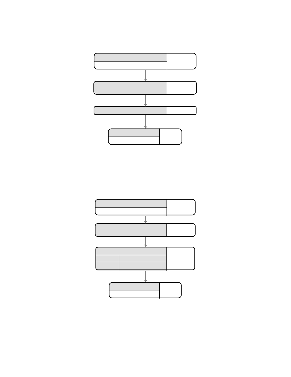
UNDERSTANDING THE PROGRAMMING FLOW CHARTS
Enter User Password
6 5 4 3 2 1
Status LED's flash
Description
Responce
from
controller
Keys to be
pressed at
keyboard
QUICK START PROGRAMMING GUIDE
Once all the connections are made the following procedure will allow you to test a Card.
1. Note check that the correct card technology has been selected for the reader input being used
(see Engineers menu 04 and 05 on pages 19 and 20). Proximity is default.
2. Then register your cards (see User menu 07 page 7).
3. Next enable a card (see User menu 04 page 8).
4. Now test by presenting the card you enabled to the reader: The reader LED will turn green and
the lock relay will open for 3 seconds.
3. USER MENU
The menu functions available and default factory settings are as follows:
Users
Menu #
Description
Default
Settings
* 00
User Password
6 5 4 3 2 1
* 01
Access Codes (Guest Cards)
None
* 03
Future Use
-
* 04
Add Card
-
* 05
Remove Card
-
* 07
Register Card Pack
-
* 08
Future Use
-
* 09
Future Use
-
CARD FUNCTIONS
CARDS
The cards used with progeny systems have unique numbers that are divided into sections. These consist
of 4 digits for "Card Number", 4 digits for "Site Code" and 4 digits for "Distributor Code". The Distributor
Code is fixed and does not need to be programmed. The P3 system can use cards from any number of
site codes. Simply enter the four digits of the site code followed by the four digit card number when
programming the system
NOTE:
The site code is not printed on some cards or fobs but is documented on a cross-reference list provided
with the cards. Keep this documentation safe in case additional cards need to be ordered later.
Page 6

Document Number: MAN0006 Issue: 26 Page 6 of 52
REGISTER CARD PACK
Note that some cards have serial number printed on them. These should be used with the crossreference list, provided with cards, to determine the actual card number. The cards used with progeny
systems have unique numbers that are divided into sections. These consist of 4 digits for "Card
Number", 4 digits for "Site Code" and 4 digits for "Distributor Code". The Distributor Code is fixed and
does not need to be programmed. The P3 system can use cards from any number of site codes. Simply
enter the four digits of the site code in addition to the four digit card number when programming the
system
Enter User Password
6 5 4 3 2 1
Status LED's flash
Select Menu 07 "Register Card pack"
07
Enter first card number
60010101
Enter * as separator
Enter quantity of cards to enable
50
Finish
Status LED's stop flashing
This will register 50 cards, site code: 6001 from card 101 to 150.
Page 7

Document Number: MAN0006 Issue: 26 Page 7 of 52
ADDING CARDS
Note that some cards have serial number printed on them. This should be used with the cross-reference
list, provided with cards, to determine the actual card number.
Single card:
Enter User Password
6 5 4 3 2 1
Status LED's flash
Finish
Status LED's stop flashing
Select Menu 04 "Add Card"
04
Enter card number
60010105
Block of cards
The quickest way to enable a whole group of cards is to use the block add method shown below:
Enter User Password
6 5 4 3 2 1
Status LED's flash
Select Menu 04 "Add Card"
04
Enter first card number
60010101
Enter * as separator
Enter quantity of cards to enable
50
Finish
Status LED's stop flashing
This will enable 50 cards, Site code 6001 from card 101 to 150.
Page 8

Document Number: MAN0006 Issue: 26 Page 8 of 52
REMOVING CARDS
Single card
If a card is reported lost or stolen the card can be disabled to remove the security risk and without
affecting any other card users.
Enter User Password
6 5 4 3 2 1
Status LED's flash
Finish
Status LED's stop flashing
Select Menu 05 "Remove Card"
05
Enter card number
60010105
Should the card be found or returned use function 04 to enable it again.
Block of cards
Enter User Password
6 5 4 3 2 1
Status LED's flash
Select Menu 05 "Remove Card"
05
Enter first card number from pack
60010101
Enter * as separator
Enter Quantity of cards in pack
200
Finish
Status LED's stop flashing
Page 9

Document Number: MAN0006 Issue: 26 Page 9 of 52
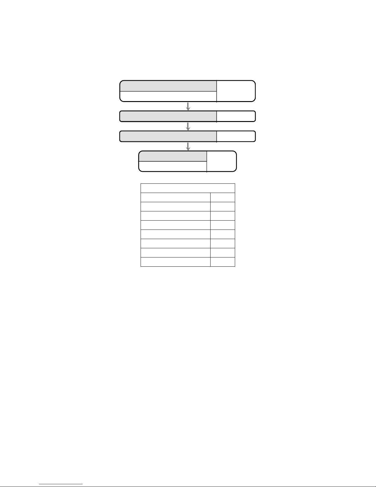
SETTING DATE-TIME
The internal clock of the P3 Controller has three main parameters:
1. Date (010100 = 1st of January 2000)
2. Time (153001 = 3:30:01 pm)
Enter current User Password
6 5 4 3 2 1
Status LED's flash
Finish
Status LED's stop flashing
Select Menu 08 "Set Date"
8
Enter date in 6 digit format "ddMMyy"
0 1 0 8 0 0
Engineers function 09 allow the time to be set. Allways set the time using 24Hr format.
Enter current User Password
6 5 4 3 2 1
Status LED's flash
Finish
Status LED's stop flashing
Select Menu 09 "Set Time"
09
Enter time in 6 digit format "hhmmss"
1 0 5 5 0 0
Page 10
Document Number: MAN0006 Issue: 26 Page 10 of 52
SETTING THE DAY OF WEEK
The day of week is only important for the daylight savings feature to work correctly. This is because the
date rule also uses the day of week to determine when to change the time.
The set the day of week use the Day of Week table below to find the day ID and enter this as a value
using the following procedure.
Enter Password
6 5 4 3 2 1
Status LED's flash
Finish
Status LED's stop flashing
Select Menu 3 "Set Day of Week"
0 3
Enter new value (1 to 7)
2 (Monday)
DAY OF WEEK IDENTIFIERS
DAY OF WEEK
ID
SUNDAY
1
MONDAY
2
TUESDAY
3
WEDNESDAY
4
THURSDAY
5
FRIDAY
6
SATURDAY
7
Page 11

Document Number: MAN0006 Issue: 26 Page 11 of 52
ACCESS CODE FUNCTIONS
The P3 controller can provide 100 access codes. Up to 100 access codes can be programmed for each
door or channel of the controller. The codes are held in slots or pigeonholes that are numbered 000
through to 099.
ADDING ACCESS CODES
Enter User Password
6 5 4 3 2 1
Status LED's flash
Finish
Status LED's stop flashing
Select Menu 01 "Access Code"
01
Enter two digit slot number
0 6
Enter new access code
0 1 3 5 6 7
Enter * as a separator
*
REMOVING ACCESS CODES
Removing Individual Access Codes
Follow the same procedure as for adding access codes except after select the slot containing the access
code in question simply press or #. This will clear the code contained at that slot.
Page 12

Document Number: MAN0006 Issue: 26 Page 12 of 52
USER PASSWORD
Passwords are the means by which the systems operator gains access to the programming functions.
This is a 6-digit number and can be changed by using the following procedure.
Changing the user password
Enter current User Password
6 5 4 3 2 1
Status LED's flash
Finish
Status LED's stop flashing
Select Menu 00 "User Password"
00
Enter new 6 digit password again
9 8 7 6 5 4
Enter new 6 digit password
9 8 7 6 5 4
Page 13

Document Number: MAN0006 Issue: 26 Page 13 of 52
ENGINEERS MENU
The menu functions available and default factory settings are as follows:
Engineers
Menu #
Description
Default Value
* 00
Password
1 2 3 4 5 6
* 01
Delay to Lock Release
0
* 02
Lock Release Duration
3
* 03
PDO Time
0 = off
* 04
Reader A technology
2 (Proximity)
* 05
Reader B technology
2 (Proximity)
* 06
Duress 1= on, 0 =off
OFF
* 07
Relay "B" mode
0 (As relay A)
* 08
Timer for "B" relay
3
* 09
Penalty Time
0
* 10
Hacker Count
5
* 12
Unlock Timer
65
* 14
* 19
Clear access codes
-
* 20
Keyboard Function
0 (Access Code)
* 21
Adding Events to be Logged
All enabled
* 22
Removing Events to be Logged
-
* 23
Enable Logging of all events
-
* 24
Card & PIN Time Zone
0
* 25
Reader A APB Configuration
0
* 26
Reader B APB Configuration
0
* 27
Relay B Time Zone
0
* 80
IP Address
0.0.0.0
* 81
Gateway IP address
0.0.0.0
* 82
Net mask (Host Bit Count)
8
* 83
Apply IP Settings
-
Page 14

Document Number: MAN0006 Issue: 26 Page 14 of 52
LOCK DELAY TIME
Lock delay time is the amount of time before the locking device is released following a valid card or the
triggering of the RQE input. This may be from 0 to 99 seconds.
Programming the Lock Delay Time
Enter current Engineer Password
1 2 3 4 5 6
Status LED's flash
Finish
Status LED's stop flashing
Select Menu 01 "Delay to Release"
0 1
Enter new value (0 to 99 seconds)
1 1
LOCK RELEASE TIME
Lock time is the amount of time that the locking device is released following a valid card or the triggering
of the RQE input. This may be from 0 to 99 seconds. If a door sensor is fitted then the anti tailgate
feature means that the lock time will be cut short once the door closes again.
Programming the Lock Release Time
Enter current Engineer Password
1 2 3 4 5 6
Status LED's flash
Finish
Status LED's stop flashing
Select Menu 02 "Lock Release Time"
0 2
Enter new value (0 to 99 seconds)
3
TOGGLE MODE
If the lock time for a particular channel has been set to zero then each time a valid card is presented or
correct code is entered, the output relay will “Toggle” to the opposite state.
Page 15

Document Number: MAN0006 Issue: 26 Page 15 of 52
Each channel has its own lock time thus either or both channels can be selected to “toggle” or “timed”
operation. One channel can be used to open a door, and the other channel used to turn on and off an
item of equipment.
Page 16

Document Number: MAN0006 Issue: 26 Page 16 of 52
PROLONGED DOOR OPEN PDO
There are connections on the control unit to allow the monitoring of the door open status. PDO is the
amount of time the door may be open before triggering an audible alarm from the control unit. This may
be from 0 to 99 seconds. If this is set to zero, the PDO alarm is disabled.
Programming PDO Time
Enter current Engineer Password
1 2 3 4 5 6
Status LED's flash
Finish
Status LED's stop flashing
Select Menu 03 "PDO Time"
0 3
Enter new value (0 to 99 seconds)
1 2
Pressing 7 and 8 together will mute the integral PDO alarm sounder. This does not affect the PDO alarm
output. The PDO will however re sound on the next alarm occurrence. To disable the PDO sound and
output permanently, program the PDO time to zero.
Page 17

Document Number: MAN0006 Issue: 26 Page 17 of 52
READER A TECHNOLOGY
The reader technology code allows different types of card readers and cards to be used. Each card
reader input can have its own technology setting.
Programming Reader technology A
Enter current Engineer Password
1 2 3 4 5 6
Status LED's flash
Finish
Status LED's stop flashing
Enter new value (0 to 99)
0 Wiegand
2 Proximity
3 26 Bit
9 Mag-stripe
13 Bar code
Select Menu 04 "Reader A
Technology"
0 4
If using Crystal readers, the correct reader technology value is 11 (8 Digit Clock and Data)
Page 18

Document Number: MAN0006 Issue: 26 Page 18 of 52
READER B TECHNOLOGY
The reader technology code allows different types of card readers and cards to be used. Each card
reader input has a separate technology setting.
Programming Reader technology B
Enter current Engineer Password
1 2 3 4 5 6
Status LED's flash
Finish
Status LED's stop flashing
Enter new value (0 to 99)
0 Wiegand
2 Proximity
3 26 Bit
9 Mag-stripe
13 Bar Code
Select Menu 05 "Reader B
Technology"
0 5
If using Crystal readers, the correct reader technology value is 11 (8 Digit Clock and Data)
Page 19

Document Number: MAN0006 Issue: 26 Page 19 of 52
DURESS ENABLE
If the duress feature is turned on, a duress alarm is generated when one enters an access code with the
last digit incremented. For example if your access code is “1 2 3 4” then if you enter “1 2 3 5” the door
will be released as normal but also the duress alarm output will go active and latch. A duress alarm can
only be cancelled by entering the valid password. While this feature is turned on each access code has a
shadow thus doubling the number of valid access codes.
If the duress feature is turned off, then “1 2 3 5” would not open the door thus only the number access
codes are not doubled.
If this value is set to 1 the duress feature is enabled and disabled if the value is 0.
Programming Duress Feature
Enter current Engineer Password
1 2 3 4 5 6
Status LED's flash
Finish
Status LED's stop flashing
Enter new value (0 to 1)
1
0 OFF
1 ON
Select Menu 06 "Duress Feature
Switch"
0 6
Page 20

Document Number: MAN0006 Issue: 26 Page 20 of 52
RELAY B MODE
Enter current Engineer Password
1 2 3 4 5 6
Status LED's flash
Finish
Status LED's stop flashing
Enter new value (0 to 9)
7
00 Lock
01 Code Channel Relay
02 Door Forced
03 Duress
04 Hacker
05 PDO
06 Tamper
07 Fire
08 Intruder
09 Control by PC
10 Link to Time Zone
11 Two Stage Release
12 Turnstile Mode
Select Menu 07 "Relay B Function"
0 7
Relay B can be configured to perform a number of different roles. By default the relay simply mimics the
lock relay and allows loads to be driven or provide voltage free contacts for other equipment such as
barriers etc.
Page 21

Document Number: MAN0006 Issue: 26 Page 21 of 52
CODE CHANNEL TIMER
Lock time is the amount of time that the locking device is released. This may be from 0 to 99 seconds. If
this value is set to zero, then each time the channel is triggered the relay will “ Toggle” to the opposite
state. If a door sensor is fitted then the anti tailgate feature means that the lock time will be cut short
once the door closes again.
Programming the CODE CHANNEL TIMER
Enter current Engineer Password
1 2 3 4 5 6
Status LED's flash
Finish
Status LED's stop flashing
Select Menu 08
"B Relay Release Time"
0 8
Enter new value (0 to 99 seconds)
3
Page 22

Document Number: MAN0006 Issue: 26 Page 22 of 52
PENALTY TIME
This feature can slow persons, trying to gain access by using successive codes, down. As soon as an
incorrect code is detected at the keyboard this penalty time is invoked, preventing any further access
attempts until the timer elapses. The factory set default penalty time is 0 seconds (Disabled).
Programming the Penalty Time
HACKER OUTPUT
Persons trying to gain access by trying successive codes can be detected and an alarm raised via the
Hacker output. The controller will count consecutive errors and when this predetermined value is
reached the alarm is generated. This alarm is latching and can only be reset by someone who knows the
password. See “Resetting alarm” later in this manual. The factory set default hacker count is 5.
TO CHANGE THE HACKER COUNT
Enter current Engineer Password
1 2 3 4 5 6
Status LED's flash
Finish
Status LED's stop flashing
Select Menu 09
"Penalty Time"
0 9
Enter new value (0 to 99 seconds)
1 0
Enter current Engineer Password
1 2 3 4 5 6
Status LED's flash
Finish
Status LED's stop flashing
Select Menu 10
"Hacker Count"
1 0
Enter new value (0 to 99)
5
Page 23
Document Number: MAN0006 Issue: 26 Page 23 of 52
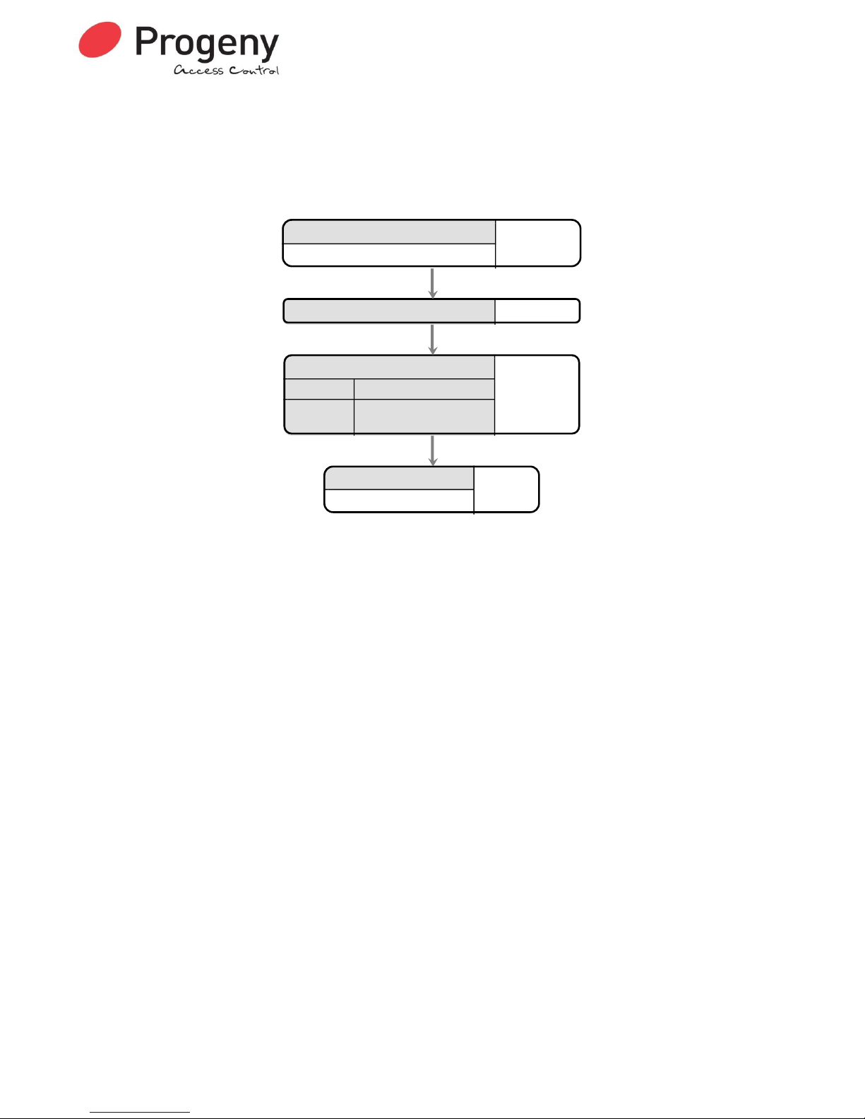
INPUT TIME DELAY
Some locking devices use monitored handles to generate Request to Exit signals. This allows the
system to detect forced door or prolonged door open signals. To ensure that the request to exit signal is
received by the controller before the lock-monitoring signal, a small delay can be put on the door
monitoring input. This ensures no false door forced signals generated by these types of locks.
Programming the Input Time Delay
Enter current Engineer Password
1 2 3 4 5 6
Status LED's flash
Finish
Status LED's stop flashing
Enter new value (0 to 1)
1
0 No delay
1 to 15
Add time delay as per bit
map (see table)
Select Menu 14 "Input Time Delay"
14
Input Delays
Bit Input
0 Mode
1 DR
2 INH
3 RQE
Page 24
Document Number: MAN0006 Issue: 26 Page 24 of 52
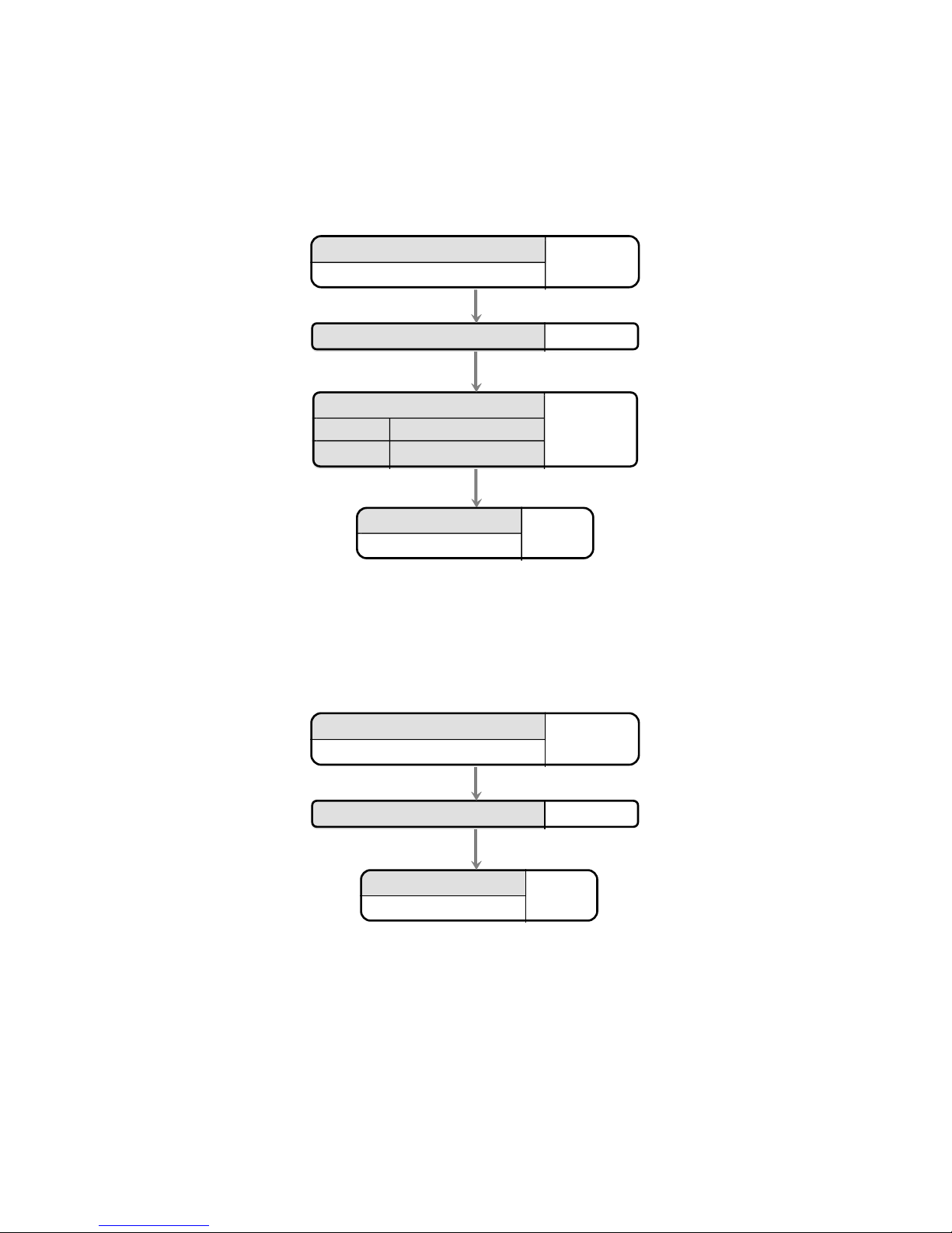
AUTO RELOCK
This function is used to control the behaviour of the controller after the door sensor input detects that the
door is opened and closed after a valid lock release. If enabled, the door will be automatically locked
once the door is closed, effectively shortening the lock release time.
Programming Auto Relock Feature
Enter current Engineer Password
1 2 3 4 5 6
Status LED's flash
Finish
Status LED's stop flashing
Enter new value (0 to 1)
1
0
Auto Relock disabled
1 Auto Relock enabled
Select Menu 15 "Auto Relock"
15
ERASE LOGGED DATA
This function will erase all logged data in the unit, and will reset the unread log event count to zero.
Erase Logged Data Function
Enter current Engineer Password
1 2 3 4 5 6
Status LED's flash
Finish
Status LED's stop flashing
Select Menu 16 "Erase Logged Data"
16
This manual is found at www.eaglesecuritysolutions.co.uk
Page 25
Document Number: MAN0006 Issue: 26 Page 25 of 52
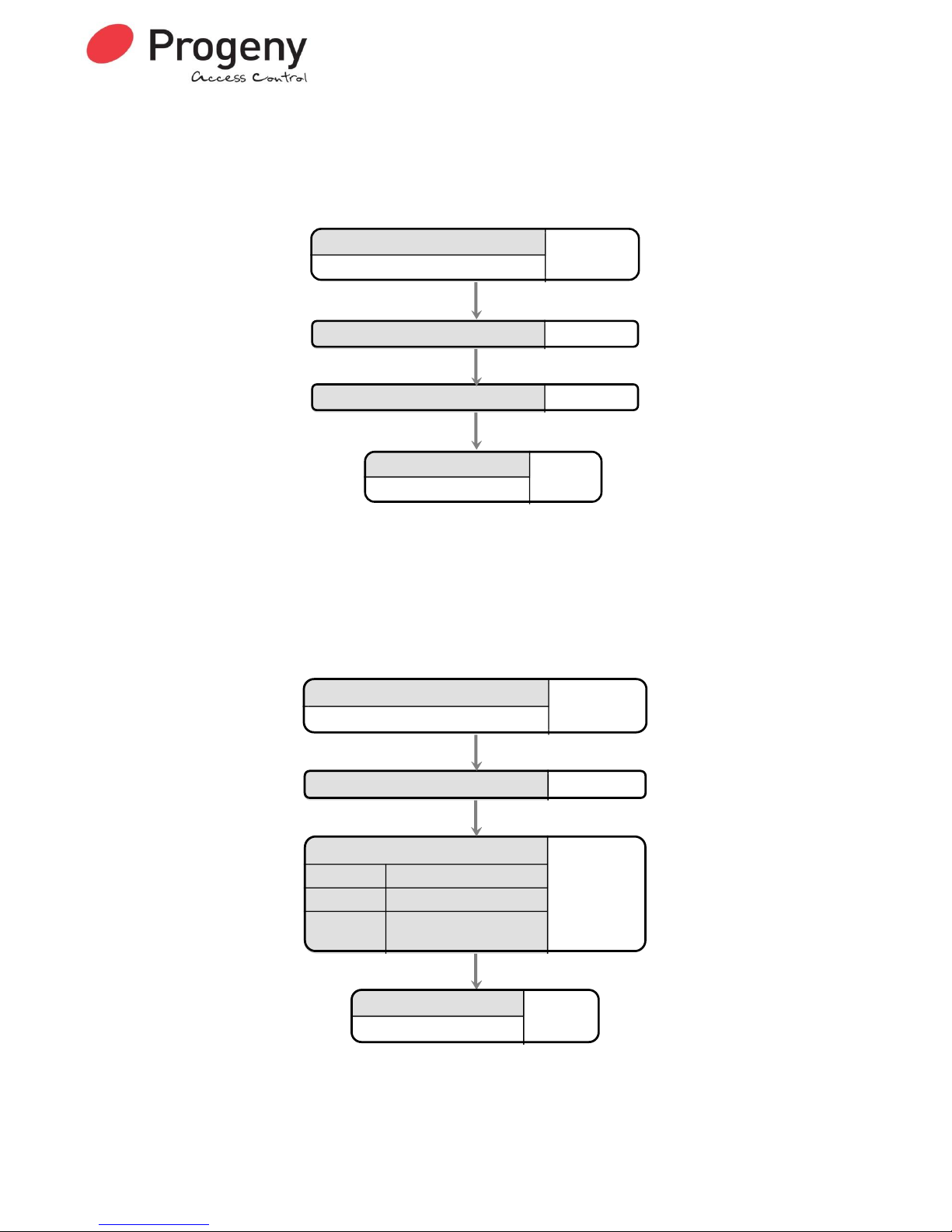
RASE CARD PACKS
This function will erase all card pack data in the controller, and will reset the card pack count to zero.
N.B. USING THIS FUNCTION WILL ERASE ALL CARD DETAILS FROM THE CONTROLLER
Erase Card Packs Function
Enter current Engineer Password
1 2 3 4 5 6
Status LED's flash
Finish
Status LED's stop flashing
Enter Card Pack Erase Password
7 4 9 1 6 2
Select Menu 17 "Erase Card Packs"
17
KEYBOARD FUNCTION
Access method is the way the system operates using cards and codes. The system can use cards or
100 codes. Alternatively the controller can be set to use virtual cards. These are entered codes entered
at the keypad but treated as card transactions by the system. This allows for code only online systems.
Programming Access Method
Enter current Engineer Password
1 2 3 4 5 6
Status LED's flash
Finish
Status LED's stop flashing
Enter new value (0 to 8)
1
0 card or 100 codes
1 Card & PIN
2-8
number of digits in virtual
card
Select Menu 20 "Access Method Switch"
20
Page 26

Document Number: MAN0006 Issue: 26 Page 26 of 52
ADDING EVENTS TO BE LOGGED
Many types of events can be logged. As well as the obvious card and keyboard transactions, PDO, Door
Forced and many more are also logged. Some of these events may not be of interest in your application.
So, a feature has been added to allow any event type to added or removed from the logging list.
Engineering functions 22 and 23 allow adding and removing of events types. Each event type has an
identification code (see the list below).
EVENT IDENTIFICATION CODES
ID
Event
ID
Event
10
Card Ok
30 - 11
Invalid Card
31
-
12
Hacker Alarm
32
Date Old
13
Card OTL
33
Date New
14
Duress
34
Eng Menu
15
Door Forced
35
User Menu
16
P.D.O
36
Card & PIN OK
17
Fire
37
Invalid PIN
20
Intruder
40
Card OVP
21
Personal Attack
41
-
22
No Card Pack
42
APB
23
Intruder Reset
43
Spare
24
Request to Exit
44
Locked By PC
25
Code Ok
45
Un-Locked By PC
26
Fire Reset
46
Un-Locked By Time Zone
27 - 47
Locked By Time Zone
ADDING EVENTS TO BE LOGGED
Enter current Engineer Password
1 2 3 4 5 6
Status LED's flash
Finish
Status LED's stop flashing
Select Menu 21
"Enable Logging Event"
2 1
Enter two digit event identifier
"PDO"
1 6
Page 27

Document Number: MAN0006 Issue: 26 Page 27 of 52
REMOVING EVENTS TO BE LOGGED
Enter current Engineer Password
1 2 3 4 5 6
Status LED's flash
Finish
Status LED's stop flashing
Select Menu 22
"Disable Logging Event"
2 2
Enter two digit event identifier
"PDO"
1 6
RESET LOGGING
You can use this facility to reset the logging so that all events are recorded without any being filtered out
Programming Logging All Events
Enter current Engineer Password
1 2 3 4 5 6
Status LED's flash
Finish
Status LED's stop flashing
Select Menu 23 "Enable All Logging"
23
E23
Page 28

Document Number: MAN0006 Issue: 26 Page 28 of 52
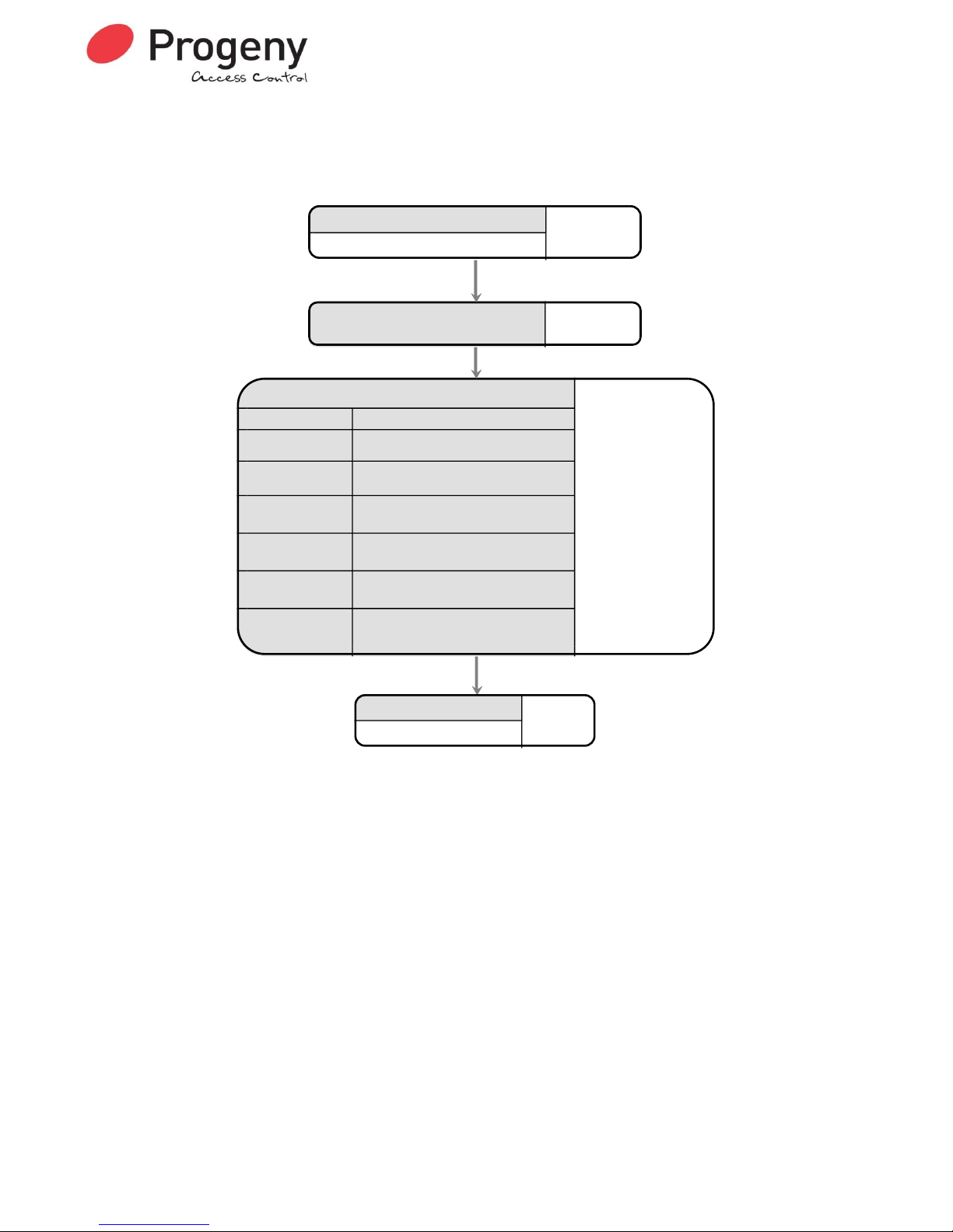
READER A APB CONFIGURATION
This programming function will select the way in which a reader will effect and/or implement the anti
pass back feature.
Programming Reader A APB Configuration
Enter current Engineer Password
1 2 3 4 5 6
Status LED's flash
Finish
Status LED's stop flashing
Enter new value (0 to 6)
1
0 Reader will not change APB
1 Reader will log card in
2 Reader will log card out
3
Reader will only allow access if card
logged out, and will then log card in
4
Reader will only allow access if card
logged in, and will then log card out
5
Reader will only allow access if card
already logged in
6
Reader will only allow access if card
already logged out
Select Menu 25 "Reader A APB
Configuraiton"
25
Page 29
Document Number: MAN0006 Issue: 26 Page 29 of 52
READER B APB CONFIGURATION
This programming function will select the way in which a reader will effect and/or implement the anti
pass back feature.
Programming Reader B APB Configuration
Enter current Engineer Password
1 2 3 4 5 6
Status LED's flash
Finish
Status LED's stop flashing
Enter new value (0 to 6)
1
0 Reader will not change APB
1 Reader will log card in
2 Reader will log card out
3
Reader will only allow access if card
logged out, and will then log card in
4
Reader will only allow access if card
logged in, and will then log card out
5
Reader will only allow access if card
already logged in
6
Reader will only allow access if card
already logged out
Select Menu 26 "Reader A APB
Configuraiton"
26
Page 30

Document Number: MAN0006 Issue: 26 Page 30 of 52
TWO STAGE LOCK RELEASE INTERVAL
When relay B is set for “Two Stage Lock Release” (See E07) this function sets the interval between
relay A opening and Relay B opening. A two-digit number from 0 to 99 can be entered. This is multiplied
by 10 milliseconds, thus a value of 25 would give a 250mS interval.
This can be useful when driving automatic door openers and locking the same door. Use Relay A to
power the lock and relay B to trigger the opening device shortly after.
Programming the Two Stage Lock Release Interval
Enter current Engineer Password
1 2 3 4 5 6
Status LED's flash
Finish
Status LED's stop flashing
Select Menu 28 "Two Stage Interval"
2 8
Enter new value (0 to 99 x 10
milliseconds)
2 5
NETWORK TRANSMIT DELAY
The Network Transmit Delay is used to allow the controller to interface with USB to RS485 converters.
The value entered will delay the controller from transmitting an RS 485 network response for 10ms x the
value entered. 20ms is usually enough.
Programming the Network Transmit Delay
Enter current Engineer Password
1 2 3 4 5 6
Status LED's flash
Finish
Status LED's stop flashing
Select Menu 29 "Network TX Delay"
29
Enter new value 0 to 99 ( x 10 ms)
2
Page 31
Document Number: MAN0006 Issue: 26 Page 31 of 52
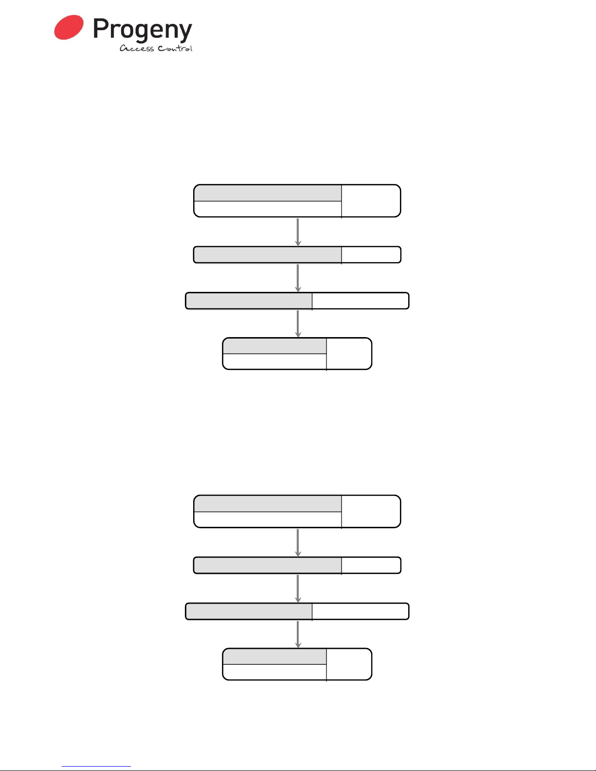
IP ADDRESS
The IP address allows the Doors access control software to communicate with the P3.net controller and
any P3 controllers connected to the (RS 485) P3 network. The IP address must be fixed and will be
assigned by the network manager for the site.
The number is usually represented in an “x.x.x.x” notation. When programming the IP address, use the *
key to represent the decimal points. Each “x” will be a number from 0 to 255. A typical IP address would
be 192.6.32.200, entered as 192*6*32*200.
Programming the IP ADDRESS
Enter current Engineer Password
1 2 3 4 5 6
Status LED's flash
Finish
Status LED's stop flashing
Select Menu 80 "IP ADDRESS"
8 0
Enter new value (192.6.32.200)
1 9 2 * 6 * 32 * 200
GATEWAY ADDRESS
The gateway or router address, allows communication between LAN segments or subnets. The gateway
address should be the IP address of the router connected to the same segment as the P3.net controller.
The network manager should be able to supply this information.
The gateway address is represented in an “x.x.x.x” notation as for the IP address. When programming,
use the * key to represent the decimal points. Each “x” will be a number from 0 to 255. A typical IP
address would be 192.6.32.1, entered as 192*6*32*1.
Programming the GATEWAY ADDRESS
Enter current Engineer Password
1 2 3 4 5 6
Status LED's flash
Finish
Status LED's stop flashing
Select Menu 81 "GATEWAY ADDRESS"
8 1
Enter new value (192.6.32.1)
1 9 2 * 6 * 32 * 1
Page 32

Document Number: MAN0006 Issue: 26 Page 32 of 52
NETMASK
The IP address is a 32-bit number. The net mask divides the bits of the IP address into “Net” and “Host”
parts. Normally the netmask is represented in the “x.x.x.x” notation, e.g. 255.255.255.0. The last number
“0” represents the 8 zeros of the 32bit netmask. It is this quantity of zeros that we need to program into
the P3.net controller. To program this into a P3.net controller we just state how many bits are used for
the “Host” part, In this case 8. The network manager should be able to supply the netmask required. Use
the table on the following page find the “Host Bits” value to program using engineer’s function 82.
Programming the NETMASK
Enter current Engineer Password
1 2 3 4 5 6
Status LED's flash
Finish
Status LED's stop flashing
Select Menu 82 "NETMASK"
8 2
Enter new value :
Class A = 24
Class B = 16
Class C = 8
8
Netmask to Host Bits Lookup table
Look up the net-mask supplied by the network manager and read off the Host bits value to program into
the P3.net controller.
Class
Net-mask
Host Bits
C
255.255.255.254
1
C
255.255.255.252
2
C
255.255.255.248
3
C
255.255.255.240
4
C
255.255.255.224
5
C
255.255.255.192
6
C
255.255.255.128
7
C
255.255.255.0
8
B
255.255.254.0
9
B
255.255.252.0
10
B
255.255.248.0
11
B
255.255.240.0
12
B
255.255.224.0
13
B
255.255.192.0
14
B
255.255.128.0
15
B
255.255.0.0
16
A
255.254.0.0
17
A
255.252.0.0
18
A
255.248.0.0
19
A
255.240.0.0
20
A
255.224.0.0
21
A
255.192.0.0
22
A
255.128.0.0
23
A
255.0.0.0
24
Page 33
Document Number: MAN0006 Issue: 26 Page 33 of 52
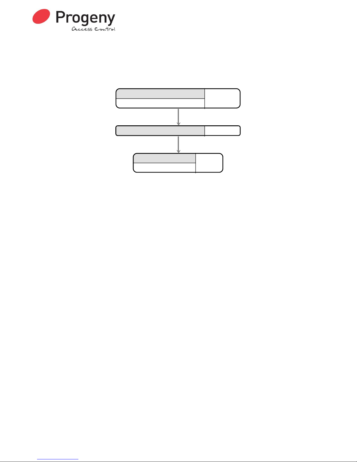
APPLY IP SETTINGS
Once any changes have been made to the IP settings have been made this function must be used to
apply the settings. This process takes approximately 7 seconds. During this time communications will
stop. At the end of this time you should be able to communicate with the P3.net and any connected P3
controllers using the new IP settings.
APPLYING IP SETTINGS
Enter current Engineer Password
1 2 3 4 5 6
Status LED's flash
Finish
Status LED's stop flashing
Select Menu 83 "APPLY IP SETTINGS"
8 3
Page 34
Document Number: MAN0006 Issue: 26 Page 34 of 52
TECHNOLOGY 7 CORPORATE ID
This function sets up the corporate ID code for HID Corporate 1000 format cards. This works in
conjunction with technology 7, which must be selected in order for this format to operate correctly.
Programming the Corporate ID
Enter current Engineer Password
1 2 3 4 5 6
Status LED's flash
Finish
Status LED's stop flashing
Select Menu 90 "Technology 7
Corporate ID"
90
Enter new value 0 to 4095
1234
CARD ISSUE CHECKING ENABLE
This function turns on or off the card issue checking function. Allows up to two digits of a cards number
to be defined as a card issue field. This function is used in conjunction with the custom card formatting
table, values 40, 46, 60 and 65. The issue number feature can only be used with online systems and is
mutually exclusive to the use of PIN’s.
Programming the Card Issue Checking Function
Enter current Engineer Password
1 2 3 4 5 6
Status LED's flash
Finish
Status LED's stop flashing
Enter new value (0 to 1)
1
0
Issue checking disabled
1
Issue checking enabled
Select Menu 91"Card Issue Checking
Enable"
91
NB This function is only available in firmware versions 3.17 and above.
Page 35

Document Number: MAN0006 Issue: 26 Page 35 of 52
ENGINEERS PASSWORD
The passwords are the means by which the systems operator gains access to the programming
functions. This is a 6-digit number and can be changed by using the following procedure.
Changing the Engineers Password
RESET USER PASSWORD
It can be useful for the engineer to reset the user password. By entering the engineering menu and
select function 99 the Users Password will be reset to the default “654321”
Resetting the Users Password
RESTORING FACTORY SETTINGS
Should you require to "reset the controller" at any time or in the event of the Programming code or
access codes being forgotten the factory settings may be restored. To do this push and hold down the
push button located in the corner of the control PCB located within the enclosure. Hold this for 5 to 6
seconds. Wait for the LED flash. The Controller will now use the factory settings for all codes and
timings. See Tables below for these settings.
Note this will also remove all programmed cards and access codes. This procedure does not remove
any IP address, Gateway or Subnet Mask values from the Ethernet port on the P3.net controller.
Enter current Engineer Password
1 2 3 4 5 6
Status LED's flash
Finish
Status LED's stop flashing
Select Menu 00 "Engineer Password"
0 0
Enter new 6 digit password again
0 0 7 6 5 4
Enter new 6 digit password
0 0 7 6 5 4
Enter current Engineer Password
1 2 3 4 5 6
Status LED's flash
Finish
Status LED's stop flashing
Select Menu 99 "Reset User Password"
9 9
Page 36

Document Number: MAN0006 Issue: 26 Page 36 of 52
Installation
Mounting
The optimum location for the controller depends on the application. As a general Guide:
Always mount the control equipment on the secure side of the door.
If the user needs to program the unit from the keyboard on the front panel, mount at head height in
an accessible location with reasonable light.
Mount as close as possible to the door(s) to be controlled (less than 100m).
Offer the opened back of the enclosure up to the wall where the unit is to be mounted and mark the
location of the fixing dimples on the wall. Drill and plug the wall. Bring in mains supply and other cables
that are to enter via the rear cable access holes. Screw the controller to the wall.
WARNING: Extreme caution must be used when opening the controller housing. DO NOT touch
any connections or components other than the reset button. Avoid touching any of the
terminations with a metal object such as a wristwatch or jewellery.
Power
The P3 Controller should be connected to a 24 Hour 220/240V mains supply. A fused spur should be
used for this purpose. The cable used to connect the mains supply should be 0.75 to 2mm2. A fused
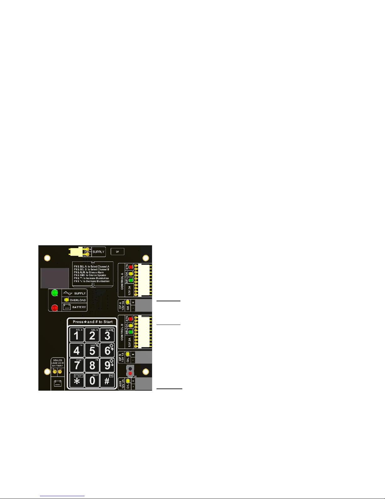
terminal block is provided for mains; observe the polarity when making these connections.
Battery
Supply
Indicates Connection
and Status of the
Main Supply
Indicates Connection and
Charge Status of Battery
Front Panel Indicators
When designing an access control system it is important to make sure that the power supply is not
overloaded. The built in power supply of the P1 and P3 range of controllers is capable of providing power
for most standard applications. However, there may be situations where additional power supplies are
required. These notes are intended to help you determine when this is the case.
Each enclosure can house one or two door controllers. The 5A PSU in the enclosure supplies 1A at 12V
to each controller channel.
Power Supply Maximum Loads
To protect external wiring each output from the power supply has an individual current limit or resettable
fuse. There are overload LED indicators next to each output port that will light if the overload protection
is activated. The maximum loads on the PSU terminals are as follows:
Power Port
Connection Type
Overload Protected
Voltage
Battery Charger
Spade Terminal
1A
13.8V
Control A
Grey 10 Pin Cable
2A
13.8V
Control B
Grey 10 Pin Cable
2A
13.8V
OP A
Terminal Block
1A
13.8V
OP B
Terminal Block
1A
13.8V
Aux
Terminal Block
2A
13.8V
Page 37

Document Number: MAN0006 Issue: 26 Page 37 of 52
Controller Output A
Resettable Fuse 2 Amp
Controller Output B
Resettable Fuse 2 Amp
Output A
Resettable Fuse 1 Amp
Output B
Resettable Fuse 1 Amp
Auxiliary Output
Resettable Fuse 2 Amp
Battery Charger Output
Current Limit 1 Amp &
Resettable Fault Fuse 1 Amp
Capacitive Keyboard. Unlock
by Pressing # (Fun) key and
the * (Start) key together.
Indicates Connection
and Status of the
Main Supply
Indicates Connection and
Charge Status of Battery
Optional Deep Discharge
Protection Relay
DC Supply
Overload
Indicators
Voltage Preset
Budgeting
Note that the above table shows the current limit of each connection and does not show the total budget
available. Total available current at any one time is 5A. When budgeting for the load it is the Peak
current values of the devices that will be connected that should be used.
Cables
Pay close attention to the current rating of cables that are connected to this power supply and any fitted
equipment. In particular the 2 Amp outputs, typical alarm cable is 7 strands of 0.2mm is only rated at 1
Amp. Check with your supplier of the cable you are using.
Battery
We recommend fitting a 12V 7Ah battery in the event of a mains failure. Batteries should be serviced at
regular intervals (24 month is a respectable period).
IMPORTANT
If rechargeable batteries are to be fitted then they must be of the correct type. The power supply is
designed to charge sealed lead acid batteries. Do not connect NiCad, Dry Cell batteries or any other
chemistry of battery.
Power up sequence should be: Mains first then Battery
Power down sequence should be: Battery first then Mains
CONNECTIONS
LOCK & RELAY B
Locking devices fall into two main categories: "Fail Secure" and "Fail Open". The fail secure type
requires power to release the door while the fail open type require power to hold the door locked. The
following diagrams show the connection, to the Card channel, of these two types of locking device.
The B relay provides voltage free contacts and is normally slaved to the "Lock" relay. The "B" relay can
be programmed to operate independently of the lock relay either for the code channel or one of the
alarm-outputs.
The locking device may be one of many different types but they fall into two main categories, "FAIL
SAFE" and "FAIL SECURE". Magnets, Sheer Magnets and some Strikes & Bolts are Fail-Safe. If not
sure consult the supplier.
The locking device should be wired to the control PCB terminals that are marked "LOCK". There are
three terminals:
Page 38

Document Number: MAN0006 Issue: 26 Page 38 of 52
Connect the negative wire to the “LOCK 0V” terminal. Connect the positive wire to either the “LOCK VA”
if the locking device is FAIL SECURE or the “LOCK VR” for FAIL-SAFE.
Back E.M.F Suppression
It is important to check that the locking device is suppressed. Any electromagnetic device will produce a
Back E.M.F when power is removed. This can interfere with and even damage other electronic
equipment. Most good locking devices will already have suppression fitted. If not you should fit an
appropriate suppression device across the coil.
In the case of solenoid operated locks a flywheel diode will do. Connect the cathode to the positive and
the anode to the negative terminal of the coil. The diode will need to be rated at the full operating current
of the coil.
Do not use a diode for a mag-lock, as this will cause an excessive delay to the release of the door. A
MOV or VDR is a far better choice. Polarity is not critical, but make sure the rated voltage is greater than
the normal operating voltage of the lock.
A more detailed explanation of Back E.M.F. can be located at our website here:
http://www.progeny.co.uk/Back-EMF-Suppression.aspx
RELAY B
NO C NC
+12/
24V
LOCK
VA VR 0V
Strike
Magn
Break
Barrie
Page 39

Document Number: MAN0006 Issue: 26 Page 39 of 52
INPUTS
RQE
The RQE “Request to Exit” input is used to trigger the lock timers. Generally this is used to provide
egress where the locking device does not provide mechanical override such as a magnet. It may allow
be used to provide a remote opening button for receptionist’s desk or interfacing to a video or intercom
door entry system.
DR Input
The door monitor input allows the detection of door forced (DF) and prolonged door open (PDO)
conditions. It is important to note that if the "DF" facility is required, an exit button is essential. If the exit
button is pushed or the correct access code is entered at the keyboard, then the locking device will be
released for the “lock time”. For the duration of the lock time and an extra period called the “PDO time”
the P1-controller will allow the door to be open without generating an alarm. However, if the door is left
open too long then an alarm will be generated at the terminal marked "PDO" This output switches to 0V
in alarm.
This DR input may be wired to any switch that detects when the door is open, the switch being closed
when the door is closed. If the door is not being monitored a wire link must be fitted between the “DR”
input and the “0V” terminals.
Some door magnets have built in monitoring, this can be used for PDO and Door Forced monitoring but
is not suitable if the system is to be used in an interlock situation. As a general rule always use separate
door sensor for the DR input.
PRG Input
A Key Switch may be provided to simplify the changing the access codes.
RQE DR MD PRG
INPUTS
Door
Push
0V
Page 40

Document Number: MAN0006 Issue: 26 Page 40 of 52
ALARMS
This diagram shows the three main ways that alarm devices can be connected to the controller. All the
alarm outputs are open collector transistors that switch to 0V when active. Any inductive loads, such as
relay coils or electromechanical buzzers should have suitable suppression fitted. A diode is sufficient for
a relay coil. Connect the bar end (cathode) to the +ve.
The PDO alarm sounder is shown powered from the access control PSU. The extra load should be
accounted for and care should be taken that the alarm device voltage rating is the same as that selected
for the lock load.
The door forced alarm is shown connected to an external power supply. Note that the -ve of the external
PSU is connected to the 0V of the access control unit.
The Hacker and Duress outputs are shown connected to a “Digital Communicator” . Check that
communicator will accept the open collector as an input trigger. Note again that the 0V of the DC
communicator is connected to 0V of the access control unit.
Relay B can also be made use of if voltage free contacts are required for any of the four alarm outputs.
See Engineers programming menu 07.
0V DUR PDO DF HCK
ALARMS
RELAY B
NO C NC
+12/
24V
DC
Communicat
or
Hacker
Duress
PDO Alarm
Door Forced
+ve
-ve
-ve
+ve
0V
External
-ve
+ve
Page 41

Document Number: MAN0006 Issue: 26 Page 41 of 52
STATUS INDICATORS
All the status outputs are open collector transistor driven. When active the transistor switches the
terminal to 0V. Any externally connected devices should be connected between that terminal and the
+12V available at the keyboard terminal block. Any inductive loads, such as relay coils or
electromechanical buzzers should have suitable suppression fitted. A diode is sufficient for a relay coil.
Connect the bar end (cathode) to the +ve.
Buzzer
This is provided for backward compatibility with earlier controllers. Also were the
speaker output cannot be used. The sounds from this type of output are limited to long
& short beeps and trill.
LED
This is a repeat output for the status indicator on the front panel. This is especially
useful when programming from a remote connected keyboard.
STATUS LED
LED state
Meaning
OFF
Standby
On
Lock released or Interlock from another door
Flashing
Programming Mode
Speaker
The P3 controller is capable of giving more informative sounds via this connection. This output is
primarily intended to drive an external speaker. However, in practice many buzzers including those on
the 2058 and 2040 give a quite reasonable reproduction.
BUZ LED SPK
STATUS
Page 42

Document Number: MAN0006 Issue: 26 Page 42 of 52
KEYBOARD
The keyboard interface allows for code or pin to be used for access control and
to allow remote programming of the standalone system. The interface uses a
binary coded decimal (BCD) scheme to reduce the number of connections
required. When a key is pressed the A, B, C, & D terminals are pulled to 12V in a
combination representing the key. It useful to note that the keys 1,2,4 & 8 pull A,
B, C & D respectively.
When a key is pressed the keyboard LED will extinguish.
Cable:
Always use a screened non-twisted cable for keyboard. More than one keyboard
can be wired in parallel for Code in Code out applications. The screen of the cable should be connected
to the earth stud of the controller. Keep the pigtail of the screen as short as possible once the cable has
entered the enclosure. The inner cores can then make the rest of the journey to the terminal blocks.
Keyboard Connection Table
Controller
2040
2011
2121
KB 2000
Scramble
External
Telephone
Style
12V
+12V
2
+12V B B 5 B C C 4 C D D 3 D
0V
0V 1 0V
LED
LED 7 -
SPK
BUZ - -
BUZ - 9
BUZ
RQE - -
-
Earth Stud
Metal Work
Metal Work
E
KEYBOARD
12V A B C D 0V
KEYBOARD
Page 43

Document Number: MAN0006 Issue: 26 Page 43 of 52
CARD READERS
Reader A, Reader B:
Only one reader may be connected to each input. The two
reader inputs can be configured to operate as “Card in
Card out” or as dual height. See notes on “Dual” in DIP
switch settings.
Cable:
Always use a screened and none twisted cables for card
readers. Don’t exceed the 100m cable limitation. The
screen of the cable should be connected to the earth stud
of the controller. Keep the pigtail of the screen as short as
possible once the cable has entered the enclosure. The
inner cores can then make the rest of the journey to the terminal blocks.
Card Reader Connection Table
Controller
2058
2075
2030
2052
3800
Progeny
Proximity
Magnetic
Stripe
Barcode
Point Prox
Crystal
Reader
12V
+12V
+12V
-
Red
+12V
5V - -
Red
-
-
DAT
D1
DATA
Violet
White
X
CLK
D0
CLOCK
Green
Green
Y
0V
0V
0V
Black
Black
0V & D
Yellow
LED
LED1
LED
Brown
- A BUZ
- - - - B
SPK
BUZ
BUZ
- - -
EARTH STUD
Earth
Earth
Matt Black
Drain
-
READER B
LED 0V CLK DAT 5V 12V
RDR B
READER A
LED 0V CLK DAT 5V 12V
RDR A
Page 44

Document Number: MAN0006 Issue: 26 Page 44 of 52
INTERLOCKING
Interlocking allows two or more doors to work together creating an airlock system. This works by each
controller informing others of the door status. This is done using the interlock input and the interlock
output.
INTERLOCK OUTPUT: This output becomes active if either the Door sensor input is open or the lock
output is active. In other words the door is insecure.
INTERLOCK INPUT: This input prevents the controller from initiating an unlock sequence. This applies
to all possible sources including RQE, Card reader, Keyboard, Network command.
The lamp drives allow indication of interlocked status at the door.
Tip: When commsioning remove the interlock connections and test each doors operation first. Then
connect the interlock and verify the interaction of the two doors. Three and four way interlocks can be
constructed using the 2069 interlock-programming module. See the separate data sheet for more
information.
DOOR
LMP O/P LMP I/P
OUT IN
INTERLOCK
LMP O/P LMP I/P
OUT IN
INTERLOCK
RQE DR MD PRG
INPUTS
RQE DR MD PRG
INPUTS
0V
12V
12V
Traffi
c
Traffi
c
Door
Door
DOOR
Page 45
Document Number: MAN0006 Issue: 26 Page 45 of 52
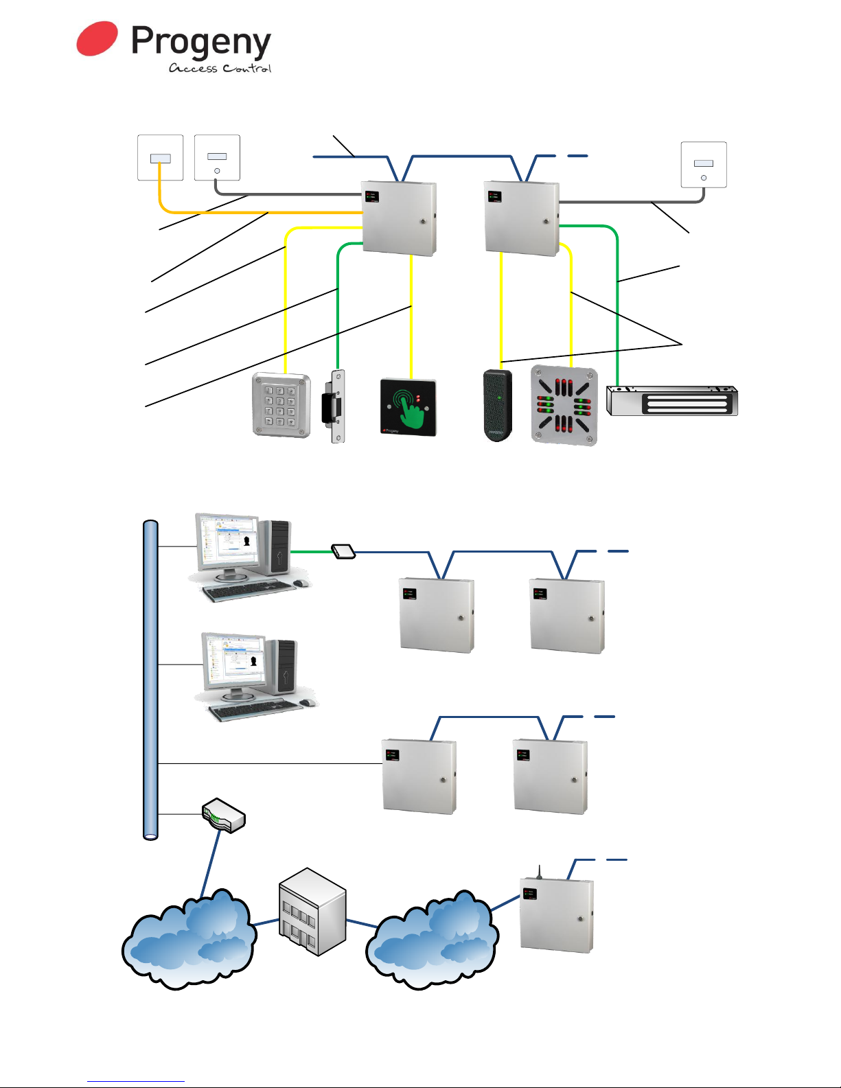
P3 & P3.net Cabling Diagram
P3 Network
(RS 485)
Up to 16
Controllers /
Doors
(1000 metre max)
P3.net
3002
P3
3001
2121
Keyboard
Strike or
Mag
3 Core
Mains Flex
(3A)
1 Amp
Alarm
(100m Max)
Screened Twisted pair
(Belden 8132 or equivalent
1000m max)
Fuse
Strike or
Mag
Fused Spur
8 Core
Screened
(100m Max)
RJ45
Data Point
Cat 5 Patch
Lead
(1m max)
8 Core
Screened
(100m Max)
3810 Touch
Switch
3858
Reader
2058
Reader
Fuse
8 Core
Screened
(100m Max)
1 Amp
Alarm
(100m Max)
3 Core
Mains Flex
(3A)
Fused Spur
P3 & P3.net Hardware System Diagram
Mobile
Network
(GPRS)
Internet
P3 Network
(RS 485)
USB
Server PC
Client
Workstation
P3 Network
(RS 485)
Up to 16 Controllers
BELDEN 8132
or equivalent
(1000 metre max)
Ethernet 10/100 Base T
P3.net
3002
P3
3001
P3
3001
P3
3001
P3.GPRS
3006
Router
Mobile
Service
Provider
USB
Adapter
3107
LAN / WAN
(TCP / IP)
Up to 16 Controllers
BELDEN 8132
or equivalent
(1000 metre max)
Up to 16 Controllers
BELDEN 8132
or equivalent
(1000 metre max)
Page 46

Document Number: MAN0006 Issue: 26 Page 46 of 52
NETWORK CONNECTIONS
The network used to link the controllers back to a central point is “RS 485”. This allows full duplex
communication and requires a special cable type (Belden 8132, 8131 or equivalent).
The 8132 has two twisted pairs the 8131 has one pair. Both have an overall screen and drain wire.
When pulling the cable into place, be careful to avoid Fluorescent lighting ballast's and large mains
transformers, motors and switchgear. When terminating strip back the cable sufficiently to identify the
twisted pairs of cores.
IMPORTANT PLEASE NOTE
It is important to use the colour coding and keep the twisted pairs for connections as shown
above. At each door controller the incoming and outgoing screens should be connected
together. Connect the drain wires to the chassis earth stud at the first controller only. It is also
important the network be one daisy chain with no spurs or loops.
RS232 SELECTION JUMPER SETTINGS
2 5 Jumper links set to RS232 connection
1 6
JP4
In order for the controller to communicate with a PC via an RS232 interface, the jumper settings for JP4
must be set as shown above.
RESET BUTTON
The reset button allows the engineer to perform a factory reset. This resets all parameters to the factory
default values and removes all Cards, Guest Cards and Access Codes.
The reset button needs to be held for 5 seconds to start the reset sequence. The keyboard LED will
display a flashing sequence to indicate the start of factory reset.
If access to the control PCB is not possible there is an external procedure to achieve the same thing.
The procedure consists of first removing power to the controller, then while holding number “9” key, reapply power.
P3.net Controller
P3 Controller
Page 47

Document Number: MAN0006 Issue: 26 Page 47 of 52
CONTROL BOARD LEDS
READER "A" & "B" LED
Meaning
Off
Stand by
On
Door opened
Flashing sequence
Error
NETWORK LED’s
Meaning
POLL LED Flashing
Data specific to the controller received
DATA LED Flashing
Data on the network
OFF
No Network Activity
KEYBOARD LED
Meaning
On Pulsing off
Key Press
Flashing sequence
Factory Reset In progress
LED
Meaning
Interlock In
Interlock input is active
Interlock Out
Interlock output active
Lock & Relay B
Relay Energised
OVERLOAD INDICATORS
The supply for the access control system is regulated and current limited for each logical section. The
5V supplies for the two card readers is separately regulated and limited to 100mA
each.
A yellow LED indicates an overload on either of these connections. This prevents
faults from affecting other parts of the system. The “NET” led indicates a fault in that
part of the system and the “12V” indicates a load exceeding the 500mA at the
reader and keyboard connections combined. The “12/24V” led is for the lock supply
that appears at the LOCK VA, VR and the 12/24V terminals.
OVERLOAD
12/
24V
12V
Page 48

Document Number: MAN0006 Issue: 26 Page 48 of 52
SPECIFICATION
CONTROLLER PARAMETERS
Event Memory 2000 time date stamped
Time Zones 64
Time elements 255
Calendars 8
ETHERNET
Speed 10Base-T or 100 Base-T (Auto-Sensing)
Connector RJ-45
Cable Category 5 (90metres max)
Protocols TCP/IP, UDP/IP, ARP, HTTP, DHCP
Management Via programming keyboard on front panel
CARD CHANNEL
Cards with host site code Up to 10,000
Custom Card Formats 36 as standard + user defined
Reader Technologies Proximity, Wiegand, Barcode,
Magstripe, Biometric. Crystal
Two Reader Inputs “Card in” – “Card Out” or Dual Height
Reader supplies 12V @ 500mA current limited
Cables 8 core screened 100m
CODE CHANNEL
Access codes 100 (Slots 00 to 99)
Access Code length 4, 5 or 6 digits
Virtual Cards up to 10,000 (1 to 8 digits)
Penalty Timer 0 to 99 seconds
Code Timer 1 to 99 seconds
0 = Toggle mode
Cables 8 core screened 100m
CONTROLLER
Dimensions: 310mm, 330mm, 90mm
User password 6 Digits
Engineer password 6 Digits
Keypad Functions PDO Mute
Sounder Mute
RELAY OUTPUTS
Lock Output Relay 12V DC Applied & Removed
Relay B contact ratings 3.0 Amps at 30V DC
Relay B Modes 12
Lock Timer 1 to 99 seconds
0 = Toggle mode
Anti Tailgate Feature As Standard
NETWORK
RS 485 (2 wire) Half Duplex
Cables BELDEN 8133, or 8132 1000m max
INTERLOCK
Connections In & Out with lamp drives
Lock & Doors status Yes
INPUTS
Request to exit input Normally open contact
Door monitor input Closed contact when door closed
Auxiliary Fire, Intruder, Tamper
Page 49

Document Number: MAN0006 Issue: 26 Page 49 of 52
ALARMS
Door forced alarm output 100 mA switched to 0V
PDO alarm output 100 mA switched to 0V
Hacker alarm output 100 mA switched to 0V
Duress output 100 mA switched to 0V
STATUS
LED Readers, Keyboard
Sound Speaker (48 Ohms min)
Buzzer 100mA
PROGRAMMING
User Functions
User Password
Access Codes
Register cards
Add Cards
Remove Cards
Date, Time & Day of Week
POWER SUPPLY
Supply Voltage In 230 V AC
Supply Power 75 Watts
Battery Charger Sealed Lead acid 12V 7Ahr
DC Outputs 12V (13.8V)
Page 50

Document Number: MAN0006 Issue: 26 Page 50 of 52
ADVANCED FEATURES
User Formats
Occasionally magnetic stripe cards that already in use by the end user need to be used for access
control. Shuffling the digits around so that the card number and site code appear in the right places for
the access control system can do this. Technology option 9 “Magnetic Stripe” pre-loads a template
mapping for standard Progeny access cards. Engineer functions 40 to 54 and 60 to 74 allow this
mapping to be modified.
User Defined Format (Engineers menu 40 to 54 and 60 to 74)
When the controller reads a card, the number is loaded into a 32-digit buffer. If there are more than 32
digits, the surplus digits are ignored apart from being used to calculate and check the LRC.
Functions 40 to 54 store a two-digit number 1 to 32 representing the ordinal positions of digits the in
buffer. If a particular digit needs to fixed to a set value. Storing a value 50 to 66 does this. 50 represents
a digit 0, 51 a 1, 52 a 2 and so on. 60 to 66 represents hexadecimal A to F. Thus field separators can be
represented (0Dh, "=").
Function 54 allows the numbers to referenced from the beginning or the end of card information. If left
justified the digits are counted from the start sentinel forward. If right justified the digits are counted from
the end sentinel backward.
The following example is the template used for barcode public format:
EXAMPLE Barcode Public format
Functi
on
Destination
Source
*40
Site code digit 5
50
*41
Site code digit 4
5
*42
Site code digit 3
6
*43
Site code digit 2
7
*44
Site code digit 1
8
*45
Card number digit 5
50
*46
Card number digit 4
9
*47
Card number digit 3
10
*48
Card number digit 2
11
*49
Card number digit 1
12
*50
Dist Code digit 4
1
*51
Dist Code digit 3
2
*52
Dist Code digit 2
3
*53
Dist Code digit 1
4
*54
Read from 0 = Left, 1 = right
0
The fifth digit of the site code and card number are both fixed to 0 by using “50”. The card is read from
the start (*54 = 0). The fourth digit of the card number is taken from the ninth digit from the start of the
card and so on.
Page 51

Document Number: MAN0006 Issue: 26 Page 51 of 52
USER DEFINED CARD FORMAT PLANNING TABLE
READER A
READER B
Destination
Functio
n
Source
Function
Source
Site code digit 5
*40
50
*60
50
Site code digit 4
*41 *61 Site code digit 3
*42 *62 Site code digit 2
*43 *63 Site code digit 1
*44 *64
Card number digit 5
*45
50
*65
50
Card number digit 4
*46 *66 Card number digit 3
*47 *67 Card number digit 2
*48 *68 Card number digit 1
*49 *69
Dist Code digit 4
*50 *70
Dist Code digit 3
*51 *71
Dist Code digit 2
*52 *72
Dist Code digit 1
*53 *73 Read from Left/Right
*54 *74
Page 52

Document Number: MAN0006 Issue: 26 Page 52 of 52
Quick Reference
USERS MENU
ENGINEERS MENU
#
DESCRIPTION
#
DESCRIPTION
*00
User Password
*00
Engineers Password
* 01
Access Codes
*01
Delay to Lock Release
* 03
Future Use
*02
Lock Release Duration
* 04
Add Card
*03
PDO Time
* 05
Remove Card
*04
Reader A technology
* 07
Register Card Pack
*05
Reader B technology
* 08
Future Use
*06
Duress On/Off
*09
Future Use
*07
Relay B Mode
RELAY B MODES
* 08
Timer for code channel
00
2nd Lock Relay (Default)
* 09
Penalty Time
01
Code channel
* 10
Hacker Count
02
Door Forced Alarm
* 12
Unlock time-zone
03
Duress Alarm
* 15
Auto relock
04
Hacker Alarm
* 19
Clear Access Codes
05
PDO Alarm
* 20
Access Method Select
06
Future Use
* 21
Adding Events to be Logged
07
Fire (follows input)
* 22
Removing Events to be Logged
08
Intruder (follows input)
* 23
Enable Logging of all events
09
Controlled by PC
* 24
Card & PIN Time Zone
10
Controlled by Time Zone (E27)
* 25
Reader A APB Configuration
11
Two Stage Release
* 26
Reader B APB Configuration
12
Turnstile Mode
* 27
Relay B Time Zone
* 28
Delay to relay B
* 80
IP address
* 81
Gateway Address
* 82
Subnet mask
* 83
Apply IP Changes
* 99
Reset User Password
READER TECHNOLOGY
00
Wiegand
02
Proximity (Default)
03
26 Bit
09
Magstripe
12
Lobby Entry
13
Bar Code
Commissioning Information
User Password
Engineer Password
Controller ID
IP Address
Gateway Address
Subnet Mask (Host Bit count) ie:
Std Class A = 24 = (255.0.0.0)
Std Class B = 16 = (255.255.0.0)
Std Class C = 8 = (255.255.255.0)
Date Commissioned
This manual is found at www.eaglesecuritysolutions.co.uk
 Loading...