

ProFurl NDEC 430, NDEC 530, NDEC 480, NDEC 520, NDHC 420 Installation Manual
...
MANUEL DE MONTAGE
INSTALLATION MANUAL
Enrouleurs motorisés / Motorized systems
Gamme Croisière Electrique
Cruising Electric Systems
NDEC 420
NDEC 430
NDEC 480
NDEC 520
NDEC 530
Gamme Croisière Hydrauliques
Cruising Hydraulic Systems
NDHC 420
NDHC 430
NDHC 480
NDHC 520
NDHC 530
www.profurl.com
Indice B
Gamme Régate Electriques
Racing Electric Systems
NDER 420
NDER 430
NDER 480
Gamme Régate Hydrauliques
Racing Hydraulic Systems
NDHR 420
NDHR 430
NDHR 480

2
LEXIQUE
GLOSSARY
Mécanisme d’émerillon
Halyard swivel mechanism
2 manilles lyre
2 bow shackles
Multitop
Wrapstop
2 demi paliers
2 half bearings
Eclisse supérieure
Upper bearing holder
Vis auto-taraudeuse
Self-taping screw
1/2 lune
C-shaped washer
Emerillon complet
Complete Halyard
swivel
Vis de jonctions
Set screws
Eclisse de raccordement
Joining bearing holder
2 demi paliers
2 half bearings
Vis de jonctions
Set screws
Vis de jonctions
Set screws
2 demi paliers
2 half bearings
Eclisse de raccordement
Joining bearing holder
Avale ridoir
Turnbuckle cylinder
Vis avale ridoir
Turnbuckle cylinder
screws
Vis de jonctions
Set screws
Gaine intermédiaire
Intermediate luff extrusion
Gaine inférieure
Lower luff extrusion
Vis tétons
Nippled screws
Eclisse inférieure
Lower bearing holder
2 demi paliers
2 half bearings
Guide ralingue
Luff rope feeder
Sangle Velcro®
Velcro® webbing
Tête de gaine
Upper stop
Jonction complète
Complete joining kit
Gaine inférieure équipée
Complete lower extrusion
Eclisse inférieure complète
Complete lower bearing holder
Gaine intermédiaire équipée
Complete intermediate extrusion
Guide ralingue complet
Complete luff rope feeder
Manivelle
Crank
Handle
Axe de dépannage
pour perçeuse
Square drive for
drilling machine
Kit de motorisation
Motorisation kit
Boitier relais
Contactor unit
Façade disjoncteur
Circuit breaker
plate
Disjoncteur
Circuit breaker
Manchon entraineur
Shape adapter
Vis d’arret de gaine
Lower extrusion
stop screws
Manille
Shackle
Bouchon
de manivelle
Crank
socket cap
Motoréducteur complet
Complete gear motor
Vis de tube embase
Screw for stainless
steel tube
Bague de fourreau
Anti corrosion bushing
Fourreau de tube
Stainless steel ring
Tube embase inox
Stainless steel tube
Cardan
Toggle
Axe d’étai
Stay pin
Axe de cadène
Stemhead
chainplate pin

3
TABLE DES MATIERES / CONTENTS
Note aux installateurs
Ce manuel devra être remis à l’utilisateur qui en prendra connaissance avant l’utilisation du matériel. Il devra être
conservé à bord.
Note to riggers
This installation manual should be given to the boat owner, who should read it before using the system. It must be kept
on board for future reference.
Réception du matériel
Le matériel voyage toujours aux risques et périls du destinataire. Il y a donc lieu d’effectuer une vérication dès réception
et émettre toutes réserves ou exercer tous recours à l’encontre du transporteur dans les délais réglementaires.
Receipt of goods
All goods must be checked on delivery and the purchaser should claim from the carrier within seven days in the event
of loss or damage.
Préparation 4 Preparation
Principe général de montage 5 Quick overview
Identication du système 5 Identication of the system
Identication de vos terminaisons d’étai 6 Identication of your forestay terminals
Montage de la partie mécanique 7-11 Fitting the mechanical part
Montage de l’option avale ridoir 12 Fitting an optional turnbuckle cylinder
Mise à longueur des gaines 13 Cutting extrusions to length
Montage des gaines sur l’étai 14 Fitting the extrusions onto the stay
Jonction entre les gaines 15 Connecting the extrusions
Montage de la gaine et de
l’éclisse inférieure
16 Fitting the lower extrusion and the
lower bearing holder
Montage de l’émerillon 16 Fitting the halyard swivel
Montage du mécanisme sur les gaines 17 Fitting the mechanism onto the extrusions
Montage d’un kit de motorisation 17 Fitting a motorization kit
Pose du Multitop 18 Fitting the Wrapstop
Installation à bord 18 Fitting on board
Réglage du ridoir 19 Adjusting the turnbuckle
Montage de la partie électrique (NDE) 20 Wiring of electric systems (NDE series)
Montage de partie hydraulique (NDH) 21 Wiring a hydraulic system (NDH series)
Montage du guide ralingue 22 Fitting the feeder
Hisser la voile 22 Hoisting the sail
Réglage de la hauteur de l’émerillon 23 Adjusting the position of the halyard swivel
Spécications concernant les voiles 23 Sail specications
Boîtier de commande 23 Remote control
Conseils d’utilisation & 1ère utilisation 24 Operation tips & using the system for the 1st time
Utilisation de la manivelle de secours 24 Using the system manually
Pièces détachées 25-32 Spare parts
Pièces détachées pour axe d’étai et cadène 33 Spare parts for forestay and chainplate pins
Dimensions des enrouleurs PROFURL 34-35 Dimensions of PROFURL systems
Dimensions boitier relais, disjoncteur et façade 36 Dimensions of contactor unit, circuit breaker and plate
Dimensions des cardans 37 Dimensions of toggles
Entretien 38 Maintenance
Conditions de garantie 39 Limited warranty
Nous contacter 40 Contact us

4
Sur toutes les vues, le haut de l’étai est représenté du côté droit, et le bas du côté gauche.
Every picture shows the top end of the stay on the RIGHT HAND side, and the bottom end of the stay on the LEFT
HAND side.
PRÉPARATION
PREPARATION
Les enrouleurs PROFURL ont été conçus pour être installés facilement.
Pour le montage quelques outils courants sont nécessaires.
Il est conseillé de démonter l’étai en totalité et de réaliser le montage sur le sol, sur une surface propre et plane.
PRÉCAUTIONS PRÉLIMINAIRES:
Vériez ou faites vérier par une personne compétente que l’étai est en bon état. Pour information la durée de vie
moyenne d’un étai est d’environ 10 ans.
The PROFURL reeng-furling systems are designed to be easily tted.
A set of common tools is required for the installation.
For easier installation remove the forestay from the boat and assemble the system on a clean and level surface. Protect
the system from any damage.
PRELIMINARY CAUTION:
Please ensure your forestay is checked by an accredited/skilled person. Recommended forestay life is about 10 years
(6 years in Australia).
ATTENTION:
> Sur un étai existant: AVANT de démonter l’étai, notez le réglage du ridoir (s’il existe), ou la position de l’œil inférieur
de l’étai entre les lattes-ridoir.
> Sur un nouvel étai: installez au préalable le nouvel étai, réglez le ridoir (si ridoir), et notez son réglage, ou la position
de l’œil inférieur de l’étai entre les lattes-ridoir.
CAUTION:
Existing forestay: before attempting to remove the forestay and if a turnbuckle – or adjustment plates - are tted, mark
the position of adjustment of the turnbuckle – or adjustment plates. This will ensure the original length of the forestay
is maintained.
New forestay: t the new stay to the boat rst and mark the position of adjustment of the turnbuckle– or adjustment
plates.
5
PRINCIPE GENERAL DE MONTAGE
QUICK OVERVIEW
1. Monter provisoirement sans les gaines le kit de motorisation à la base de l’étai et/ou l’avale ridoir si cela est le cas.
Ceci permettra:
> de vérier la position du mécanisme au dessus de la cadène,
> de vérier que toutes les pièces livrées avec l’enrouleur se montent correctement à la base de l’étai.
2. Mesurer la distance entre le haut du kit de motorisation, ou le haut du cylindre de l’avale ridoir (si option avale ridoir),
et l’extrémité du sertissage supérieur de l’étai, pour déterminer la longueur des gaines.
3. Re-démonter le kit et commencer le montage de l’enrouleur proprement dit.
1. Temporarily t the motorization kit without the extrusions to the lower end of the stay and / or the turnbuckle cylinder
if any. This will ensure that:
> the height of the kit above the stem head chain plate suits your needs
> all components delivered with your system perfectly t to the stay lower terminal.
2. Measure the distance between the top edge of the motorization kit or turnbuckle cylinder (if any) and the lower end
of the top swage terminal.
3. Dis-assemble the kit from the stay and start to permanently t the system to the stay.
IDENTIFICATION DU SYSTEME
SYSTEM IDENTIFICATION
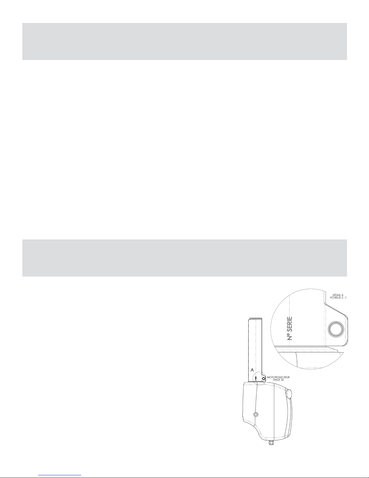
Chaque enrouleur motorisé Profurl fait l’objet d’une identication. Vous
trouverez sur le coté du motoréducteur le numéro de série. Sur l’émerillon le
type de modèle (C420 etc...) est également spécié.
Dans le cas d’une procédure SAV, merci de relever ce numéro
d’identication
Each motorized system has a serial number located on the side of the gear
motor. On the swivel, the type of the model is specied (C420 etc...). In case
of warranty claim, thanks to communicate this serial number.
Seq.1

6
IDENTIFICATION DE VOS TERMINAISONS D’ÉTAI
IDENTIFICATION OF YOUR FORESTAY TERMINALS
Certaines terminaisons supérieures d’étai ne sont pas adaptées à la pose d’un enrouleur, et imposent une modication
de l’étai:
> Terminaisons à boule (principalement mâts Isomat et Z-Spars). Solution: placer une terminaison boule-œil dans la
tête de mât (réf ACMO réf EBO ou équivalent), raccourcir le câble d’étai en tenant compte de la longueur de la nouvelle
pièce, et sertir sur le câble une terminaison à chape articulée.
> Terminaisons à T. Solution: modier l’ancrage de l’étai sur le mât pour pouvoir disposer d’un câble comportant une
chape articulée.
TERMINAISON SUPERIEURE DE L’ETAI
FORESTAY UPPER TERMINAL
Some terminals require special attention when assembling a reeng system:
> Ball terminals (mainly found on Isomat and Z-Spars masts). Solution is to t a ball-eye terminal (Ref: stemball eye
639 from Norseman-Gibb or similar) into the mast head, to shorten the wire by a few inches, and to have a new swage
terminal pressed onto the wire.
> T terminals (mainly found on Kemp / Selden masts with fractional rig). Solution is to t a new stay attachment onto the
mast, and have a toggle swage terminal pressed onto the wire.
TERMINAISON INFERIEURE DE L’ETAI
FORESTAY LOWER TERMINAL
En fonction :
> de vos terminaisons d’étai,
> du type d’installation choisi :
- motoréducteur près du pont avec le tube d’embase recoupé
ou
- motoréducteur surélevé avec le tube d’embase à la longueur maxi.
vous devrez:
> vérier que votre étai corresponde aux spécications requises.
> suivre les séq. page 10 et 11 pour raccorder la partie basse de l’enrouleur sur la terminaison inférieure de l’étai.
According to :
> the type of forestay terminals
> the type of installation selected:
- gear motor low to the deck with the shortened stainless steel tube
- gear motor raised from deck with the stainless steel tube(length maxi),
you should :
> check that your forestay matches the required specications.
> follow seq. page 10 and 11 to connect the drum mechanism onto the lower end of the forestay.

7
MONTAGE DE LA PARTIE MECANIQUE
FITTING THE MECHANICAL PART
Les enrouleurs PROFURL motorisés sont montés sur l’étai comme les enrouleurs manuels en ce qui concerne:
- les gaines et leurs jonctions. Voir pages 14 à 16,
- l’émerillon (pages 16 et 23) et le Multitop (page 18).
Le moto-réducteur est monté en lieu et place du mécanisme de tambour des enrouleurs manuels.
The PROFURL motorized headsail reeng-furling systems are designed to be tted over the existing forestay.
The following components are identical to a PROFURL manual system:
- extrusions and connectors. The gear motor replaces the drum mechanism found on a manual PROFURL
system. See pages 14 to 16.
- halyard swivel (pages 16 and 23) and Wrapstop (page 18)
ADAPTATION DE L’ETAI D’ORIGINE
ADAPTATION TO THE ORIGINAL FORESTAY
Le cardan (voir page 2) fourni avec l’enrouleur motorisé doit être monté directement entre la terminaison
inférieure de l’étai (œil) et la cadène, sans interposition d’une pièce quelconque.
The toggle (please see page 2) supplied must be attached directly onto the stemhead chainplate and to
the bottom eye of the forestay. No other tting should be inserted between the toggle and the chainplate.
Mesurer précisément la longueur de l’étai, d’axe en axe, et le noter.
• Si l’étai comporte des lattes et un œil, veuillez repérer la position de l’œil entre les lattes
• Si l’étai comporte un ridoir, veuillez repérer le réglage du ridoir pour obtenir la quête de mât et la
tension d’étai requises.
Accurately measure the overall length pin to pin of your forestay.
• If an eye and adjustment plates are tted please mark the position of the eye between the plates.
• If a turnbuckle is tted, please mark the adjustment position of the turnbuckle : this will maintain your existing mast
rake and forestay tension.
ETAI D’ORIGINE A OEIL ET LATTES
ORIGINAL FORESTAY WITH EYE AND AJUSTMENT PLATES
ADAPTATION DE L’ETAI
a) Supprimer impérativement les lattes
b) Remplacer les lattes par le cardan fourni
• Si l’étai est trop court : placer les lattes recoupées en tête de mât, ou changer l’étai.
• Si l’étai est trop long, le raccourcir.
ADAPTATION OF THE FORESTAY
a) The adjustment plates should be completely removed
b) The toggle supplied with the system should replace the adjustment
• Should the forestay be too short: t the adjustment plates or a
standard toggle at the top of the stay, or t a new forestay.
• Should the forestay be too long it should be shortened to the
correct length and a new eye swaged at the bottom of the stay.
Seq.2
8
ETAI D’ORIGINE AVEC RIDOIR
ORIGINAL FORESTAY WITH TURNBUCKLE
ADAPTATION DE L’ETAI
Vous devrez disposer d’un ridoir dont la partie inférieure est une
terminaison inférieure à œil. Si ce n’est pas le cas changez ou modiez
le ridoir pour obtenir une telle conguration.
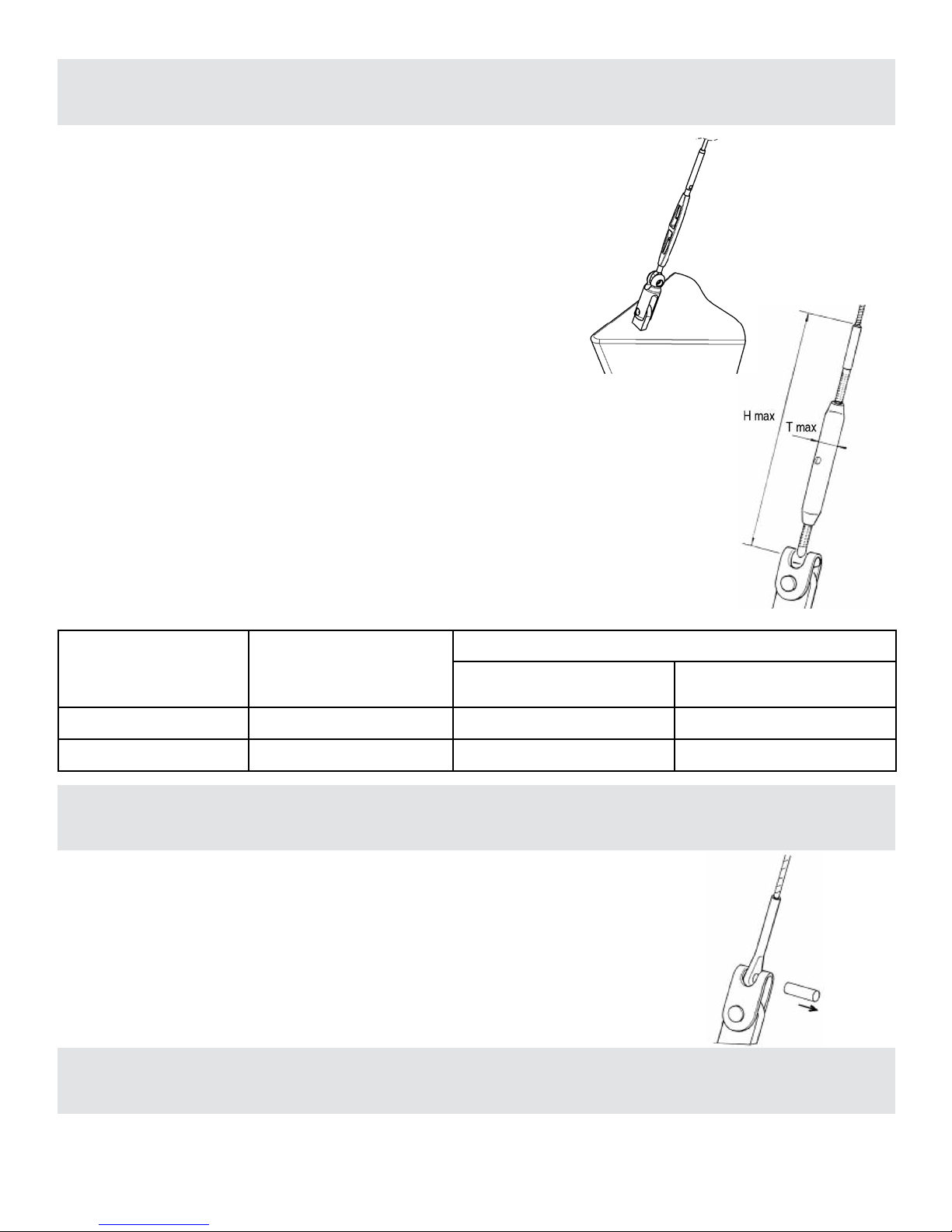
Montez le cardan PROFURL fourni directement entre l’œil inférieur du
ridoir et la cadène avec l’axe fourni, sans interposition d’une quelconque
autre pièce.
Vériez sur le ridoir réglé que les valeurs de longueur H et de diamètre
T soient inférieures aux valeurs indiquée dans le tableau 1 ci dessous.
MODIFICATION OF THE FORESTAY
You should check, modify or change your forestay to have an eye at the
bottom of your turnbuckle.
Fit the PROFURL toggle supplied between the bottom eye of the
forestay and the toggle, t the pin supplied, without using any other
part in this assembly.
Check on your turnbuckle that dimensions H and diameter T are smaller
than the ones shown on headboard 1 below.
• Should the forestay be too short : add a toggle at the top of the stay,
or change for a new stay.
• Should the forestay be too long : shorten the wire and have a new
turnbuckle with an eye terminal swaged at the bottom end of the stay.
• Dans le cas ou l’étai est trop court, ajoutez une chape en haut de
l’étai ou changez l’étai.
• Dans le cas ou l’étai est trop long, réduisez la longueur du câble
et rajoutez à l’extrémité basse de l’étai un nouveau ridoir avec une
terminaison à oeil serti.
ETAI D’ORIGINE A CHAPE
ORIGINAL FORESTAY WITH AN EYE JAW TOGGLE
ADAPTATION DE L’ETAI
Enlever la chape d’origine et xer la terminaison à oeil directement
sur le cardan fourni
ADAPTATION OF THE STAY
You should remove the captive pin to have an eye terminal. The
PROFURL toggle supplied should be tted between the eye and the
chainplate, with no other tting inserted in between.
MONTAGE SUR UN ETAI ROD:
FITTING ON A ROD STAY:
Modèles / Models T max
H max
sans avale-ridoir /
without turnbuckle cylinder
avec avale-ridoir /
with turnbuckle cylinder
NDE/NDH 420-430 40 mm / 1’ 37/64’’ 400 mm / 1 3’ 3/4’’ 765 mm / 2 6’ 1/8’’
NDE/NDH 480-520-530 50 mm / 1’ 31/32’’ - 730 mm / 2 4’ 47/64’’
Tableau / headboard 1
Seq.3
Seq.4
Seq.5
As for an installation on a standard stay (wire), you must
have an eye terminal which will be tted directly on the
toggle supplied.
Comme pour les étais en câble acier, vous devez disposer
d’une terminaison à oeil qui devra être xée directement sur
le cardan fourni.
9
REGLAGE DE LA HAUTEUR DU MOTOREDUCTEUR AU-DESSUS DU PONT
ADJUSTMENT OF THE HEIGHT OF THE GEAR MOTOR ABOVE DECK
1. Les enrouleurs PROFURL motorisés de la série NDE/
NDH peuvent être: soit montés à la hauteur standard en
utilisant le tube d’embase inox (cf page 2) tel que livré ou
en raccourcissant ce tube (si nécessaire), il est possible de
diminuer la hauteur du moto-réducteur au-dessus du pont,
dans la limite de la longueur de la terminaison inférieure
d’étai. Voir tableau 1 page 8
2. Mesurer les dimensions de la terminaison d’étai selon
le tableau 1 pour vérier si le réglage est possible, et dans
quelles limites le cas échéant. Voir dessins ci-dessous
pour L mini
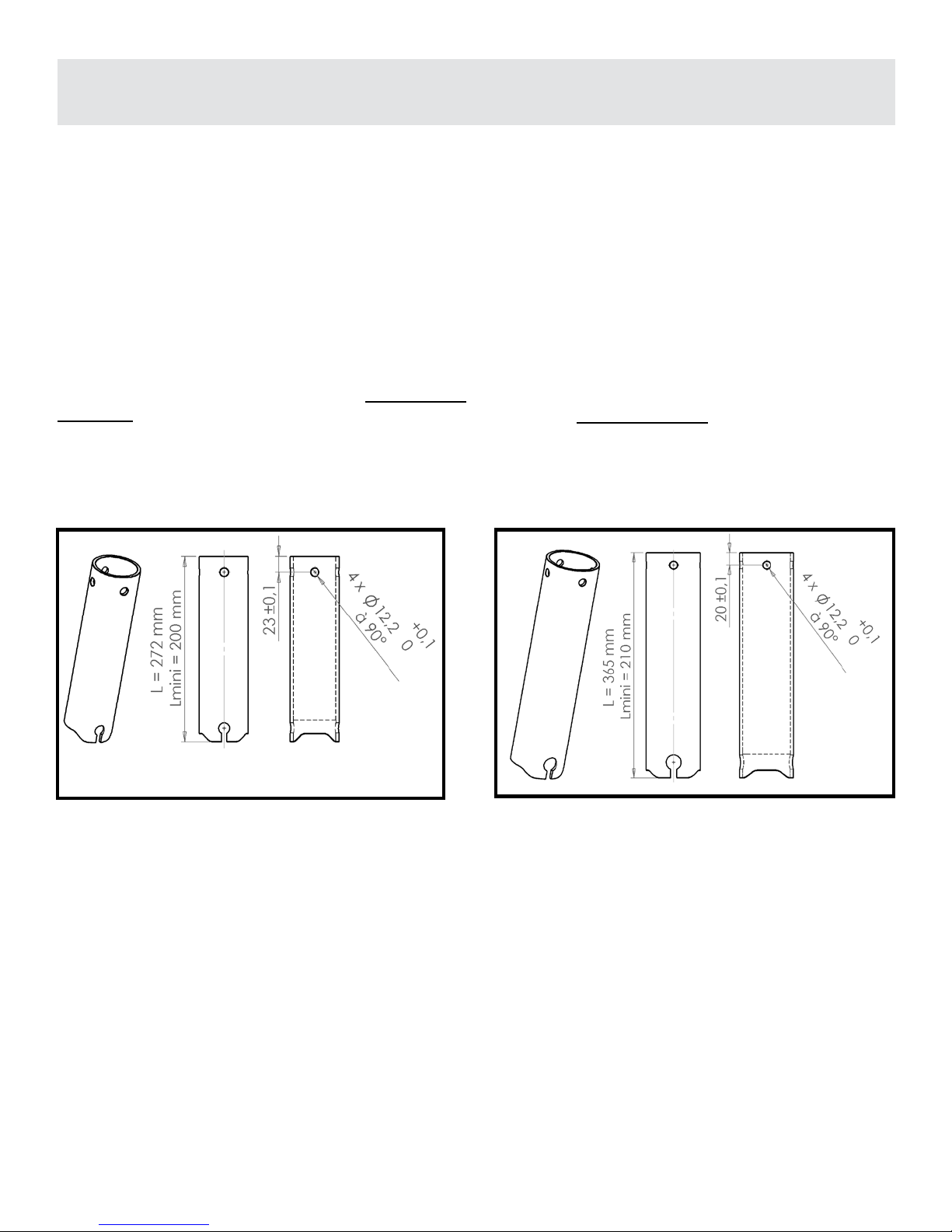
3. Raccourcir le tube d’embase inox à son extrémité
supérieure. Cette opération sera, de préférence, effectuée
par tronçonnage sur un tour pour une nition optimale.
4. Percer les trous de xation à :
1. The NDE / NDH motorized PROFURL systems allow
you to choose the height of the gear motor above deck.
The maximum allowed dimensions of the lower terminal
may also determine the minimum height of the gear
motor above deck. Please refer to headboard 1 (page
8) for dimensions.
2. Measure the forestay terminal as per headboard 1 to
check whether adjustment is possible, and until which
amount. Please refer to drawing for minimum allowed
length (L) of the tube.
3. Fitting the gear motor low to deck is achieved by
shortening the stainless steel tube. The tube should be
shortened only at the top end. It is preferable the tube is
shortened by machining in a lathe.
4. Having shortened the tube drill
5. Il conviendra enn de procéder à une décontamination
chimique, et à un polissage manuel pour
éviter toute amorce de corrosion ultérieure.
Monter provisoirement le moto-réducteur à la base de
l’étai, ce qui permettra :
• de vérier la compatibilité des différents composants
(étai, cardan, ridoir, diamètre des axes, hauteur du motoréducteur, etc..).
• de simuler le passage de l’ancre sans dommage pour le
moto-réducteur.
• d’obtenir précisément la cote permettant de dénir la
longueur des gaines (voir page 13).
5. If the tube has been shortened it is strongly recommended that it is electro and hand polished.
This will reduce discoloration and corrosion of the tube.
The gear motor should be temporarily tted at the bottom
end of the stay. This will allow you to :
• check that dimensions of the different components (stay,
toggle, chainplate, turnbuckle, clevis pins, etc…) match
together
• check that raising or lowering the anchor will not damage
the system.
• accurately calculate the length of extrusions (please refer
to page 13).
Modèles 420 - 430 / 420 - 430 models Modèles 480 - 520 - 530 / 480 - 520 - 530 models
Seq.6 Seq.7
10
MONTAGE DE LA FIXATION DU MOTOREDUCTEUR:
STANDARD FITTING OF THE GEAR MOTOR:
Seq.8
11
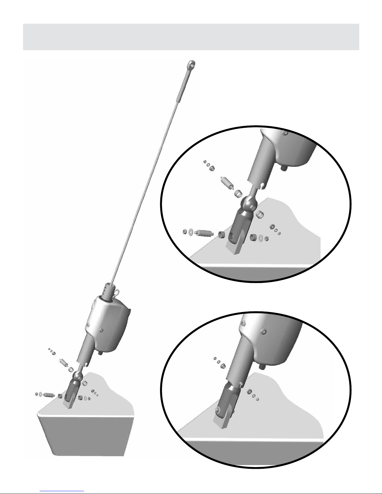
MONTAGE DU MOTOREDUCTEUR SUR LE BATEAU
FITTING THE GEAR MOTOR ON THE BOAT
Seq.9
Seq.10
Seq.11

12
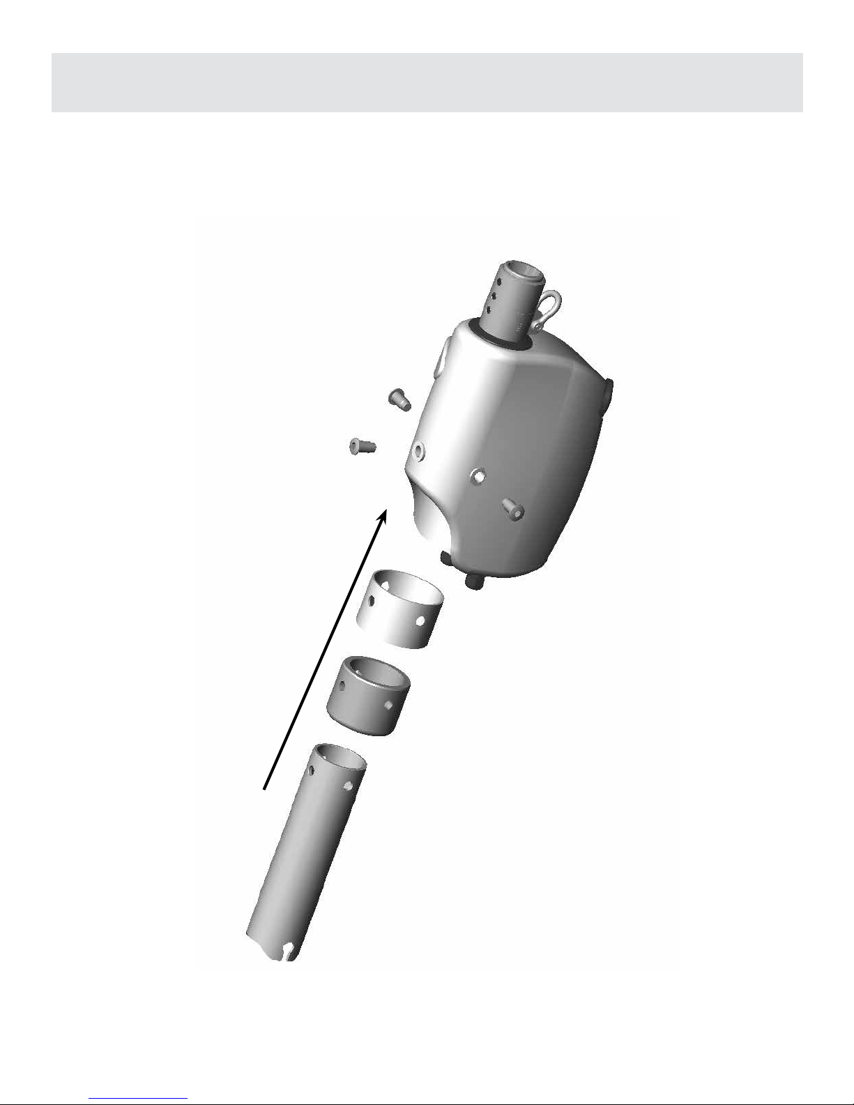
MONTAGE DE L’OPTION AVALE RIDOIR (NDE/NDH 420/C430)
FITTING AN OPTIONAL TURNBUCKLE CYLINDER
(NDE/NDH420/
C430)
Démonter les vis et retirer le manchon
entraineur.
Remove the screws and the shape
adapter.
Monter l’avale ridoir dans le
motoréducteur
Fit the turnbuckle cylinder into the gear
motor.
Monter les vis à simple téton
Fit the nippled screws.
Seq.13
Seq.12
Seq.14
Monter les vis d’arrêt de gaine en haut
de l’avale ridoir.
Fit the stop screws to the top of the
turnbuckle cylinder.
Placer le manchon entraineur en haut
de l’avale ridoir.
Fit the shape adapter to the top of the
turnbuckle cylinder.
Vérier que l’intérieur du cylindre est parfaitement propre (pas de sable, poussière etc...).
Please check that the inside of the cylinder is perfectly clean (no sand, no dust etc).
Seq.15
Seq.16
 Loading...