

Profroid QuietCO2OL Series, QuietCO2OL LT Series, QuietCO2OL MT Series, QC MT30, QC MT50 Operating Instructions Manual
...
OPERATING INSTRUCTIONS
COMMISSIONING / OPERATING / MAINTENANCE
(must be given to the end user in order to complete the operating manual during the equipment service life)
QUIETCO2OL
These operating instructions must be read at the delivery of the equipment and prior any operation on it.
Our technical department is at your disposal for any additional information (Tel : + 33 4 42 18 05 00).
This document is a translation of the French original version which prevails in all cases.
/ PED fluid group : 2
Version 9110

Modifications since the version N° 051217
Pages
- Instruction on the refrigerant charge
P5
- Clarification on the system pressure
P6
- Addition of the water cooled units
(all the
document)
- Addition of some remarks on transportation
P 14
- Warning concerning the mounting of the liquid lines
P 16
- Commissioning Instruction on water cooled units
P 18-19-20
- Recommendation on the evaporator controller selection
P 24
- Clarification of the Controller settings
P 26
- Clarification for the gascooler cleaning instructions
P 32
- Update on the service instruction
P 33-34
- Clarification of the meaning of the colour code in the refrigerant and oil charge charts
P 38
- Instruction on oil filling
P 38
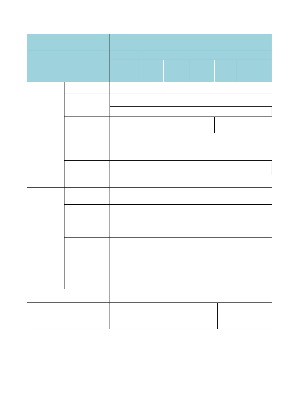
The following table aggregates all the main modifications since the last version

TABLE OF CONTENTS
SAFETY 1-3
GENERAL STARTUP INSTRUCTIONS 4-5
CAUTION FOR SAFETY 6-7
COMPONENTS 8-9
SCOPE OF APPLICATION 10
DIMENSIONS 11
HANDLING OF THE UNIT 12
SELECTION OF INSTALLATION LOCATION 13-14
REFRIGERANT PIPING WORK 15-16
COMMISSIONING 17-19
OPERATING 20
REFRIGERANT CIRCUIT DIAGRAM 21-22
ELECTRICAL CONNECTIONS 23-24
USER INTERFACE 25-27
DESCRIPTION OF THE DISPLAY 28-29
MANUAL MODE FOR THE VACUUM PROCEDURE 30
CONTROL FUNCTIONS 31
MAINTENANCE 32-34
WARRANTY CONDITIONS 35-36
ECODESIGN 37
APPENDIX 1: REFRIGERANT AND OIL CHARGE 38-42
APPENDIX 2 : ALARM LIST 43-44

SAFETY
Reminder
Carbon dioxide is a colorless and odorless gas, whose presence in excess in the atmosphere can lead to discomfort, such as
headaches, difficulty concentrating, even with low levels of concentration and nausea in the case of greater than 1000 ppm.
Carbon dioxide gas is heavier than air and is located at lowest point of spaces when they aren’t
ventilated. Machinery room must be equipped with a carbon dioxide detector as required by EN 378.
In case of carbon dioxide evacuation (vacuum draw, etc …), it is important to have a connection through safety valves discharge
pipes as required by EN 378.
As professional, the installer must :
define the operating conditions of the refrigeration equipment under his own responsibility regarding the design. This device needs
to be incorporated in machines conforming to the Machines Directive. Its commissioning is only authorized if it has been
incorporated in machines which fully satisfy the legal regulations.
complete and adapt these recommendations, if necessary, by adding other safeties and /or controls according to the
refrigeration equipment’s operating conditions.
have performed all the installing, commissioning and maintenance operations by qualified professionals and conforming with
standards EN 378, EN 14276, EN 13136, EN 13313, EN 60204 and EN 60335, the EU directives, the safety rules generally
recognized, sound engineering practice, the local regulations ; as well as those which may be set up, taking into account the
evolution of the technology and the regulations.
If the installation, the commissioning, the operating, the maintenance are not realised according to this operating instructions,
the responsibility of Profroid cannot be involved.
completely inform the customer on the control, maintenance and follow-up of the refrigeration equipment.
The devices are delivered under pressurized nitrogen or dry air (make sure at reception that material is under pressure by
using a pressure gauge) ; except dry cooler, brine air cooler.
Respect the standard for transport and handling of pressure devices.
Install device in a space with sufficient ventilation regarding standards and regulations because device is under pressure of nitrogen
; except dry cooler, brine air cooler.
Very important : before performing any servicing operation on refrigeration equipment, the electric power supply must be
turned off. The contractor or the company in charge of the installation shall be responsible for carrying out the required
instructions.
Profroid disclaims any responsibility for change(s) or repair(s) on its devices made without its prior
agreement. The devices are exclusively intended for professionals, for refrigeration purposes and for their
limits of use.
The identification of device and his range of use are written on the name plate. The name plate is stuck on device. Name plat es are
located : on the coil for heat exchangers, on the frame for racks, on the housing for condensing units, on the receiver for liquid receiver
sets and for liquid sub-assembly. The name plate is joined to this operating instructions (.pdf). The complete installation must be
designed and used not to exceed the range of use. Device is designed for a maximum ambient temperature of 38°C (as standard
configuration).
The user or operator shall ensure the control and maintenance of the equipment with qualified professional complying with the
instructions below, possibly completed by the installer. For these operations, the standards and directives mentioned above remain usefull.
This is also available during the stop of the refrigeration installation.
The average life cycle for the design of our devices is of a minimum of 10 years, provided if you follow our operating
instructions. Profroid cannot be held responsible in case of violation to the recommendations of them.
Pipings of Profroid equipment are made with different types :
in copper, standard NF EN 12735 and K65
in stainless steel, standard NF EN 10217-7 (type 304L – X2CrNi18-9 ; n° 1.4307)
These pipings must be inspected regularly following standards, sound engineering practice and local regulations in the country of use.
Some heat transfer fluids can be harmful or corrosive, and their uses must be realised in relation with their risks, if there is a
leak on pipings.
1

INSTALLATION
The loading and unloading operations must be performed with adequate handling equipment (forklift, crane, etc.) using possible lifting
points provided for this purpose.
The qualified professional should be certified and will wear individual safety equipment (protective gloves, glasses, safety shoes, etc.) ;
operators will never circulate under the load during lifting operations.
During handling, the operator will ensure a good balance to prevent the equipment from swinging.
Make sure that the equipment or its accessories have not been damaged during shipping and no parts are missing.
If devices are used in a seismic area, then the installer must apply all necessary rules.
If the appliance is installed in an area for which consideration of the external fire situation is mandatory, then the installer must make
the necessary arrangements.
Enough free space all around the refrigeration equipment should be provided to facilitate maintenance operations.
The heat exchangers must be installed in locations free of any external dust or other pollutants from the neighbourhood which could
obstruct or clog the coils.
If devices are used in a corrosive area (sea side, pollutant gas, etc.), make sure that appropriate anticorrosion protection has been
provided.
Make sure that pipings are connected to the appropriate pressurized equipment (EN378-2).
All connecting pipings must be correctly supported and clamped.
For the connection of pipings, protect sensitive components located around the permanent assemblies to be made.
Before any intervention, the operator must obstruct all the openings of the circuit (+ pressurization under nitrogen) ; except dry
cooler, brine air cooler.
Discharge pipings (outlets of safety valve for example) must be installed in view to protect people and apparatus from leakage of
refrigerant.
Make sure that flexible hoses are not in contact with metal parts.
The products added for thermal and /or acoustic insulation must be neutral with respect to support materials.
The protection devices, pipings and accessories must be protected against unfavourable effects from the environment.
Make sure that access and emergency exit ways are not obstructed to comply with the local regulations.
COMMISSIONING
Prior to electrically connect the facility, make sure that the AC power line voltage and frequency ratings correspond to the indications
on the identification plate and the power voltage is within a tolerance of + 10 % with respect to the rated value.
Specific protection is provided according to the neutral system.
Any on-site wiring must comply with the legal standards in force in the country of installation (including grounding).
Before turning on a device, make sure that :
- the electric connections have been correctly made
- the clamping screws of the various terminals are correctly tightened
Check the possible presence of locking devices of compressor antivibration elements, and remove them, if they exist.
OPERATING
Do not use the refrigeration equipment or components for any utilization other than that for which it is designed.
Comply with the special manufacturers’ recommendations contained in the manufacturers’ operating instructions.
It is strictly prohibited while the device is running to remove the guards and panelling provided by the manufacturer to protect the
user and ensure his safety.
When operating, surface temperatures above 60°C and /or below 0°C may be reached. During any servicing operation, the personnel
should be extremely careful while working on the device.
Profroid is not informed to real use of partly completed machines ; their integrations and use must comply to Machines Directive and
recommendations of this operating instructions.
Results of design calculations, checks, and test reports in relation with low voltage directive are archived.
2

MAINTENANCE / RECYCLING
The device must be checked and inspected into service, regularly, by a qualified and approved personal, following rules.
The device will be subject to preventive maintenance (EN 378) :
- external visual inspection of device,
- checks of device during running,
- checks of device corrosion.
Before working on pressurized components, shut down the facility and wait until the equipment is at the ambient (room) temperature.
Before removing the guards and panelling, turn off the device. Set it aside and make sure that no power is present.
Do not use piping to access on the equipment or to store something on theequipment.
The replacement of a safety valve must be made by the same brand of the original one.
If there is modification of type and /or brand, then the professional in charge of the replacement will do a calculation sheet following
EN 13136 and /or ask Profroid some elements.
Handle regularly the device valves in view to avoid theirs blocking on.
If a personal in charge of maintenance closed a blocked valve, this personal will must avoid the possible increase of pressure in the
part of device which is isolated.
The periodic technical checks must be made following frequencies determined by standards, sound engineering practice, end user
and installer.
Report periodic checks and analyze the data. In case of abnormalities or inconsistencies, determine the cause and correct it.
In case of hanged units (evaporator as an example), it is necessary to define an exclusion zone on the ground, to avoid the presence
of persona under the equipment.
It is important to ensure that the hinge mechanisms of moving parts are operational before all manipulations (drain pan, door,
fans mounted on hinges,…).
In general, when opening any moving parts it is necessary to accompany them or slow their opening speed to avoid casing deformations.
Lockable fan switch aren’t safety accessories.
RECYCLING
Before disassembling all or part of a device, make sure that the power supply has been switched off.
Recover for recycling by means of appropriate tools the refrigerant present in the unit or in the area of intervention after isolation
of it.
Collect all used oil and deposit it in the appropriate recycling centers. Remember to drain the oil
separator. Eliminate all or part of the device in a suitable recycling center
3

GENERAL STARTUP INSTRUCTIONS
Vacuum
To avoid inclusion of air or moisture in the refrigerant circuit,
be sure to execute vacuum drying of the entire circuit before
charging refrigerant by using a vacuum pump. Vacuum the
circuit after securely carrying out airtight/pressure testing.
> When performing vacuum drying, make sure that valve
EC1 and EC3 are fully open; please refer to chapter
“Manual mode for the vacuum procedure”.
Circuits dehydration
This operation must be carried out with all valves open (including solenoid
valves) with connection to a vacuum pump:
– to the low pressure side
– to the high pressure side
The quality of drying should not be judged by the speed at which the level of
vacuum is reached but on the effective time it is held (24 hours at 0.7 mbar is a
good standard).
The total increase in pressure after that period should not be more than 2.6
mbar. The residual moisture in the system should be less than 10 ppm.
When the installation is under vacuum, an insulation check of the motor should
not be carried out. The compressors should be started before at least 1 bar of
fluid pressure is reintroduced.
This is to prevent motor winding damage.
Refrigerant and Oil Charging
– Calculate the refrigerant and oil charge prior to charging (refer to
appendix 1).
– Execute refrigerant charging immediately after evacuation.
– Charge refrigerant R744 (CO2 refrigerant).
– Do not mix with other refrigerant.
– Always use refrigerant grade R744, moisture content must be below 10
ppm.
4

GENERAL STARTUP INSTRUCTIONS
– Oil Charging must be done through the liquid service line during vacuum operation
Method of Charging
– Use Manifold Gauges and charging hoses for CO2 only.
– Use only refrigeration quality R744.
– When charging the refrigerant fix the flexible to the frame to avoid any risks
– Use a refrigerant scale to measure correct quantity charged into the system from
the R744 cylinders.
– Close the vacuum pump and break the vacuum with vapor R744 until 7-10Bar to
avoid dry ice formation. Dry ice may block hoses and pipes and charging will be
impossible. Charge vapor in both suction and liquid line.
– Control that the expansion valve at the evaporator(s) is active. Control both
electronic pressure transmitters and manifold Gauges for correct pressure
readings.
– As vapor is drawn from the R744 cylinders, pressure and temperature inside the
cylinder will decrease. Frost at the bottom exterior of the cylinder is an evidence
that liquid R744 has evaporated inside. The reduction in pressure also causes a
slower flow rate of vapor into the system. Once the flow from the cylinder has
slowed to a low level, the cold cylinder should be disconnected and allowed to
warm. After the cylinder has been warmed up, the residual R744 can be
removed. In the meantime, another warm tank can be connected to the system to
continue the charging process.
– Do not charge liquid on compressor suction line. Only Gas.
– Charge the machine only in vapour phase. The charge should be done on the
suction line. Never charge the machine with liquid. Premature wear risk
when restarting.
– Overfilling the system may cause malfunction and compressor damage.
– Sight Glass on the liquid line does not indicate correct R744 level if 100% full.
Control superheat management is inside min-max superheat settings. ¾ of filling
level in the sight glass is ok.
– Simulate transcritical conditions when charging in low ambient conditions by
blocking the air flow into the condenser/gas cooler in order to control correct
charging level.
– Run the unite and simulate thermostat cut off, defrosting cycle or manual pump
down in order to control correct operation and R744 charge.
– In case of leakage detection and repair: empty the system completely and
refill according to the first filling charge.
5

CAUTION FOR SAFETY
As professional, the installer must:
– Define the operating conditions of the refrigeration equipment
under his own responsibility regarding the design. This device
needs to be incorporated in machines conforming to the Machines
Directive. Its commissioning is only authorized if it has been
incorporated in machines which fully satisfy the legal regulations.
– Complete and adapt these recommendations, if necessary, by
adding other safeties and /or controls according to the
refrigeration equipment’s operating conditions.
– Have performed all the installing, commissioning and
maintenance operations by qualified professionals and
conforming with standards EN 378, EN 14276, EN 13136, EN
13313, EN 60204
and EN 60335, the EU directives, the safety rules generally
recognized, sound engineering practice, the local regulations; as
well as those which may be set up, taking into account the
evolution of the technology and the regulations.
– If the installation, the commissioning, the operating, the
maintenance are not realised according to this operating
instructions, the responsibility of Profroid cannot be involved.
– Completely inform the customer on the control, maintenance and
follow-up of the refrigeration equipment.
The units have been designed for 80/80/80/120bar pressure and are equipped with discharge safety
pressure switches set at 120 bar.
Any system that is designed with PS < 80 bar can represent a risk of overpressure when it stops.
When installing a QUIETCO2OL unit into a system using a lower design pressure, the installer must
protect this system against risk of overpressure (for example by installing a safety valve) and modify
the control settings accordingly.
6

CAUTION FOR SAFETY
– Do not use other than the designated refrigerant (for charging, adding
or recharging)
– Refrigerant gas leak may cause suffocation.
– Piping, equipment components and tools should be appropriate for
use with R744 (CO2 refrigerant).
– Use of unsuitable components or those designed for HFC refrigerant
may cause serious incidents such as equipment failure and rupture of
the refrigerant cycle.
– Securely place the cover on the electrical box and enclosure panel.
Incomplete attachment may lead to penetration of water and living
creatures, meaning potential current leak and fire/electrical shock.
– Do not change the set values of the safety device.
– Using the refrigeration unit with changed values may cause failure of
the safety stop function and lead to a burst or fire.
– When abnormal operation is detected, or before starting disassembly
or repair, turn off the main power switch.
– Specified components must be used for repair.
– Use of non-specified components may cause failure of the safety stop
function and lead to burst or fire.
– Incorrect moving may cause fall or dropping of the refrigeration unit,
and cause injury.
– Request a specialty operator for disposing the refrigeration unit.
– Make sure that access and emergency exit ways are not obstructed to
comply with the local regulations.
– Protect all electrical live parts from rain or snow if doing maintenance
with unit under voltage
7
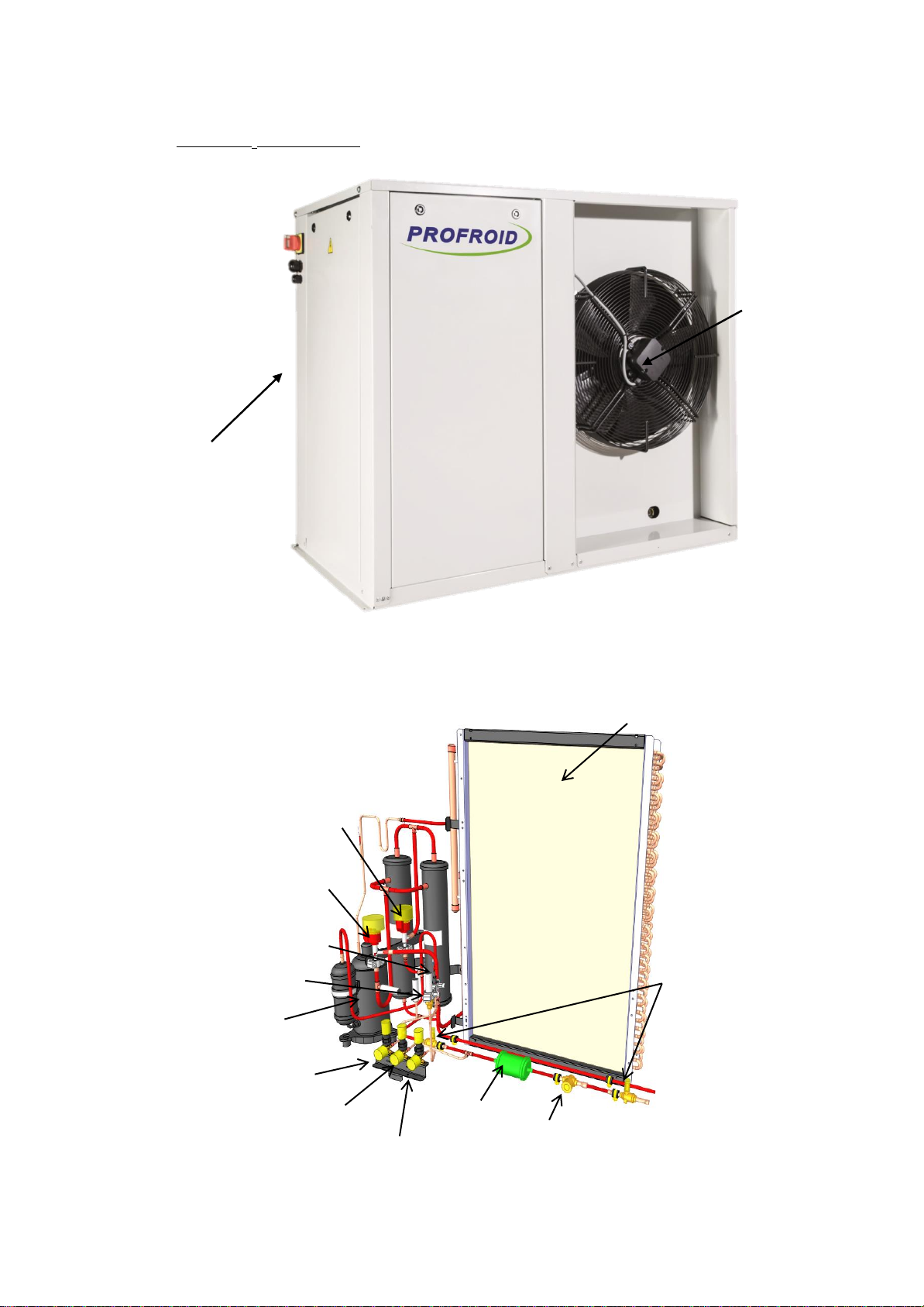
COMPONENTS
Fan
Electrical compartment
Filter drier
Service valve
liquid line
Sight glass
Compressor
HP safety pressure switch
EC1 HP Control valve
EC3 Control valve
intermediate pressure
Gas cooler
HP service valve
Service valve
Suction line
LP/HP Pressure
transducer
Shut-off valves liquid line
- QUIETCO2OL air cooled :
MT Version
8

COMPONENTS
3-ways valve
Plate Heat Exchanger
By-pass valve (gas cooler)
Sight glass
Filter drier
Service valve suction line
Compressor
EC1 HP Control valve
HP service valve
LP/HP Pressure transducer
Service valve liquid line
EC3 Control valve
intermediate pressure
Regulating thermostatic
valve
Plate Heat Exchanger
(intercooler)
3-ways valve
Plate Heat Exchanger
By-pass valve (gas cooler)
Sight glass
Filter drier
Service valve liquid line
Service valve suction line
LT compressor
Parallel compressor
EC1 HP Control valve
Oil separator
HP service valve
Solenoid valve
Pressostat de sécurité
+
Transducteur de pression HP/BP
MT Version
LT Versions
- QUIETCO2OL water cooled :
8
SCOPE OF APPLICATION
Produit
QUIETCO2OL serie
Compressor model
GMCC
Toshiba
QC
50MT
QC
30MT
QC
67MT
QC
100MT
QC
75LT
QC
167LT
Circuit du
fluide
frigorigène
Refrigerant
R744
Oil(Supplier)
Alternative oil
PAG
PZ100S
PAG VG100
PAG100 FUCHS
Evaporating
temperature
-18°C à +5°C
-32°C à -18°C
Suction
superheating
20K or below
Discharge gas
temperature
+120°C or below
Inverter
operation
45–100 tr/s
25–100 tr/s
45–100 tr/s (LT)
25-100 tr/s (MT)
Nominal
Revolution
70 rps
Ambient
Temperature
-15°C* / + 43°C (the ambient temperature can be -30°C if polar
kit heater is installed)
Relative
Humidity
10% – 90%
Allowed fluids
Water, Water-glycol (MPG / MEG – 60% maxi)
Water circuit
(water cooled
version)
Water inlet
temperature
-8°C to 35°C (nominal +7°C / +12°C)
Water mass
flow
Variable (depend on the capacity)
Pressure drop
(water side)
50 kPa or below
On/off cycle period
5 min or longer for on/off cycles
Liquid line temperature standard
receiver pressure settings
55 Bar (19°C)
35 Bar (0°C)
* Depending on the ambient temperature the use of the Polar kit should follow the following recommendations:
Ambient Temperature < -15°C Mandatory
Ambient Temperature < +5°C Recommended
10
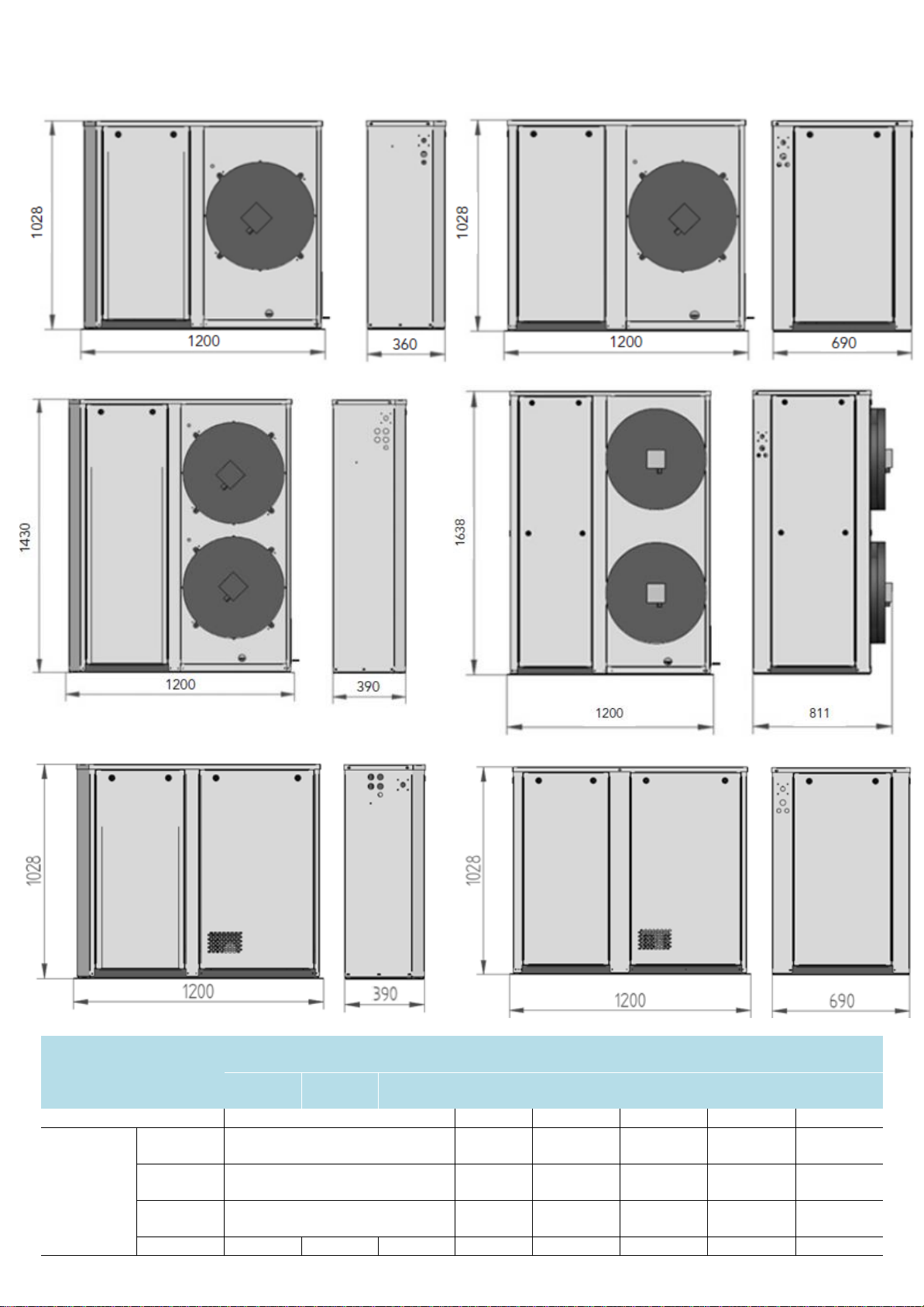
DIMENSIONS
QUIETCO2OL MT serie
Air cooled
QUIETCO2OL LT
Serie Air cooled
QUIETCO2OL serie
Water cooled
QC
MT30
QC
MT50
QC
MT67
QC
MT100
QC LT75
QC LT167
QC MT
QC LT
Fig 1
Fig 3
Fig 2
Fig 4
Fig 5
Fig 6
Dimensions
Length
(mm)
1200
1200
1200
1200
1200
1200
Depth
(mm)
360
390
690
811
390
690
Height
(mm)
1028
1430
1028
1638
1028
1028
Weight (kg)
125
130
160
185
185
210
175
250
Fig 1 Fig 2
Fig 3
Fig 4
Fig 5 Fig 6
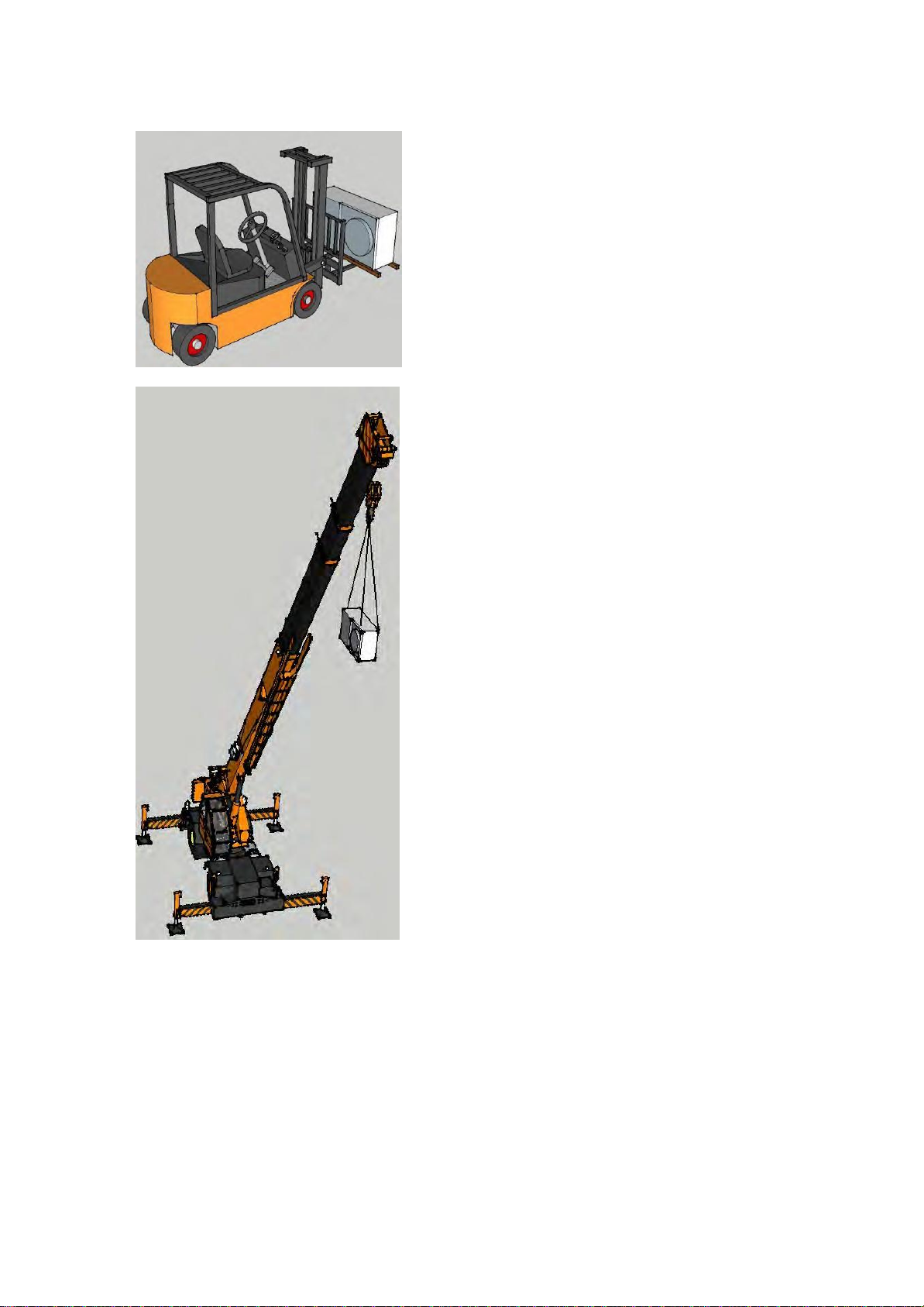
HANDLING OF THE UNIT
Carry-in Operation
- Make sure that the equipment or its
accessories have not been damaged
during shipping and no parts are
missing.
- Carry the refrigeration unit gently
by keeping the vertical position as
much as possible.
- Absolutely avoid a lay-down position
of the refrigeration unit. The loading
and unloading operations must be
performed with adequate handling
equipment (forklift, crane, etc.) using
possible lifting points provided for
this purpose.
- The qualified professional should
be certified and will wear
individual safety equipment
(protective gloves, glasses, safety
shoes, etc.) ; operators will never
circulate under the load during
lifting operations.
FORKLIFT
- When carrying the refrigeration unit
by a forklift, use a packaging wood
base or pallet for maintaining the
refrigeration unit in the vertical
position.
CRANE
– When carrying the refrigeration unit
by a crane, use a packaging wood
base or pallet for maintaining the
refrigeration unit in the vertical
position.
– Make sure that the unit is safely
secured to the lifting straps.
– During handling, the operator will
ensure a good balance to prevent the
equipment from swinging.
12

SELECTION OF INSTALLATION LOCATION
250 mm
500 mm
500 mm
1200 mm
The QUIETCO2OL Air
Cooled is intended for
outdoor installation
– The refrigeration unit must be installed
with an inclination angle 1°or below. If
devices are used in a seismic area, then
the installer must apply all necessary
rules.
– Enough free space all around the
refrigeration equipment should be
provided to facilitate maintenance
operations.
– The heat exchangers must be installed
in locations free of any external dust or
other pollutants from the neighborhood
which could obstruct or clog the coils.
– If devices are used in a corrosive area
(sea side, pollutant gas, etc.), make
sure that appropriate anticorrosion
protection has been provided.
13

SELECTION OF INSTALLATION LOCATION
2000 mm
Normal mounting
Mounting for transportation
NO air from a second unit shall be
directed towards the gas cooler of
another one!
In the case of face-to-face
installation, keep a minimum of
2000mm distance between the units.
Important: For transportation purpose the cable glands have been placed in reverse
position. Please place them in the right position before installing the unit
14

REFRIGERANT PIPING WORK
Product
Suction line
(R744)
Liquid line
(R744)
PS
MT30
9,52 mm (3/8")
9,52 mm (3/8")
80 bars
MT50
9,52 mm (3/8")
9,52 mm (3/8")
80 bars
MT67
9,52 mm (3/8")
9,52 mm (3/8")
80 bars
MT100
9,52 mm (3/8")
9,52 mm (3/8")
80 bars
LT75
9,52 mm (3/8")
9,52 mm (3/8")
80 bars
LT167
12,7 mm (1/2")
9,52 mm (3/8")
80 bars
Selection of Refrigerant Piping Size
The connection piping size for refrigeration unit is, in principle, as shown
below, but each installation should be determined by calculating pressure loss
of the piping and refrigerant flow speed and making sure no problem occurs in
the cooling capacity and oil return.
As refrigeration unit using CO2 refrigerant incurs pressure higher than when
using traditional refrigerants, it is necessary to choose adequate materials.
Make sure that piping’s are connected to the appropriate pressurized
equipment (EN378-2).
Prevent contamination of foreign objects
such as dust, metal powder, oxide scale, etc.
Since the compressor consists of high precision components, contaminants
generate scratches on the sliding surfaces, thereby increasing gas leak,
deteriorating performance, and causing excessive wear and seizure.
– Flow nitrogen gas during welding.
– Piping inside and outside must be clean.
15

REFRIGERANT PIPING WORK
Reverse-trap
P-trap
5m max height
difference
Suction line
Evaporator higher than the unit
Evaporator lower than the unit
Water OUTLET
Water INLET
Liquid line
Suction line
Dimensions :
MT30-50/LT75-167 = 1"G
MT67-100 = 1"1/4 G
Connection type : male SAE
Before any work is done on the refrigeration circuit, the holding charge must be removed.
The piping used must be of copper refrigeration quality in accordance with PED 2014/68/EC
and EN12735-1.
All piping must be correctly supported and fixed and should in no case be allowed to
restrict the operation of the gas cooler unit. For the connection of piping, protect sensitive
components located around the permanent assemblies to be made.
The products added for thermal and /or acoustic insulation must be neutral with respect to
support materials.
The protection devices, piping’s and accessories must be protected against unfavorable effects
from the environment.
The liquid line piping should be considered as an extension of the condensing unit receiver. A special
attention must be paid to the piping path and the thermal insulation. In case of exposure to heat source
(piping path exposed to the sun and not protected, piping path through non ventilated attic,…), The liquid
inside the piping can be vaporized and can cause an abnormal receiver pressure increase which could lead to
unit failure.
HYDRAULIC CONNECTIONS
Inside the unit the hydraulic circuit is in copper. The connections are protected with plastic plug.
16

COMMISSIONING
– Do not use other than the designated refrigerant (for charging, adding or recharging).
– Prior to electrically connect the facility, make sure that the AC power line voltage and
frequency ratings correspond to the indications on the identification plate and the power
voltage is within a tolerance of + 10 % with respect to the rated value.
– Specific protection is provided according to the neutral system.
– Any on-site wiring must comply with the legal standards in force in the country of installation
(including grounding).
– Before turning on a device, make sure that:
– the electric connections have been correctly made
– the clamping screws of the various terminals are correctly tightened
– Check the possible presence of locking devices of compressor antivibration elements, and
remove them, if they exist.
17

COMMISSIONING
The 3-ways valves on the water cooled version (WCO) are set from the factory. In case of replacement follow the
procedure below:
1- Complete set
Disassembly of the engine
Unscrew the engine with the dedicated tool
(control handle)
2- Check the valve position as indicated
3- Disengage the engine if necessary
18

COMMISSIONING
Thermostatic valve (water cooled version)
After replacing it make sure to set the thermostatic valve according to the factory settings. Graduation 2.5T which
correspond to a temperature of 45°C (CO2)
19

OPERATING
– Do not use other than the designated refrigerant (for charging, adding or recharging).
– Do not use the refrigeration equipment or components for any utilization other than
that for which it is designed.
– Comply with the special manufacturers recommendations contained in the
manufacturers operating instructions.
– It is strictly prohibited while the device is running to remove the guards and
panelling provided by the manufacturer to protect the user and ensure his safety.
– When operating, surface temperatures above 60°C and /or below 0°C may be
reached. During any servicing operation, the personnel should be extremely careful
while working on the device.
– Profroid is not informed to real use of partly completed machines; their integrations
and use must comply with Machines Directive and recommendations of these
operating instructions.
– Results of design calculations, checks, and test reports in relation with low voltage
directive are archived.
Water cooled QUIETCO2OL features
– The cooling fluid of the Water Cooled QUIETCO2OL must either be water or a
mixture of water and MEG or water and MPG (maximum MEG/MPG concentration:
60%).
– The inlet temperature of this fluid must be in a -8°C/+35°C range. The nominal
range is between +7°C and +12°C.
– The water circuit is equipped with a three way valve which allows regulating the by-
pass of the gascooler.
– A thermostatic control valve allows controlling the water flow which passes through
the intercooler on the LT versions. This valve operates by measuring the temperature
of the refrigerant on the CO2 outlet of the heat exchanger.
– When dimensioning the water circuit, the installer must take into account the
pressure losses of the water pipes and the exchanger(s).
– The hydraulic circuit thermal insulation is proposed in option
20

REFRIGERANT CIRCUIT DIAGRAM
QUIETCO
MT Version
OL AIR COOLED :
2
LT Version
21

REFRIGERANT CIRCUIT DIAGRAM
QUIETCO2OL WATER COOLED VERSION :
MT Version
LT Version
22

ELECTRICAL CONNECTIONS
QUIETCO2OL MT series
QUIETCO2OL LT series
QC
30MT
QC
50MT
QC
67MT
QC 100MT
QC 75LT
QC 167LT
Power supply
230 V / Single phase /
50 Hz
+ G
400 V / 3ph /50 Hz
N + G
230 V / Single
phase / 50 Hz
+ G
400 V / 3 ph /
50 Hz
N + G
Max. absorbed
current without
evaporators (Air
cooled)
13,3 A
20,7 A
27,2 A
18,5 A 18,4 A
31,4 A
Max. absorbed
current without
evaporators (Water
cooled)
12,5 A
19,9 A
26,4 A
16,5 A 17,6 A
31,4 A
Caution
Electrical compartment contains live terminals, please ensure supply is isolated before
removing the cover. Any person accessing this part of the unit should be suitably trained and
competent.
Before carrying out any maintenance work, disconnect the drive and the external control
circuits from the power supply by moving the main system switch to “off”. Once power has
been disconnected from the drive, wait at least 5 minutes before disconnecting the
electrical cables.
If consumers are powered from the condensing unit using the available circuit breakers, select
the main power supply by adding the actual consumer input current to the above values
General information
– The machine is designed in accordance with EN60204-1.
– Supplying cable must be connected on terminal of main switch.
– All cabling on site must conform to the legal standards in force in
the relevant countries and to EN60204-1.
23

ELECTRICAL CONNECTIONS
Recommendation
In order to ensure the optimal operation of the installation, we recommend the use of controller and expansion
valves from Carel connected to the unit through a Modbus connection. When using other brands of controller or
expansion valve, a special attention must be paid on the settings on site. Bad settings of these components can
lead to an instability of the system, short cycling the compressor and oil return issue, endangering the condensing
unit operation.
To avoid any overloading of the compressors, it is necessary to set a MOP (Maximum Operating Pressure) of
0°C (34,8 Bar) for MT application and a MOP of -20°C (19,7) Bar for LT applications.
24

USER INTERFACE
Types of display
There are three fundamental types of display shown to the user:
– Main display
– Menu display
– Screen for display/setting the parameters
Remark : All images below are for reference only; the user interface can be changed without prior notice.
Main display
USER PASSWORD: 1502
The software on board pRack Hecu automatically returns to the main mask 5
min after the last button was pressed. An example of the main mask is shown in
the figure, highlighting the fields and icons used.
1. Time and date
2. Main values
3. Unit status (unit off) compressors and fan status (unit on)
4. Active alarm signal and manual operation
5. Access further information mask (menu branch A.a) by
pressing Note the information shown on the main mask varies
according to the system configuration and type of control value
used (pressure, temperature)
25

USER INTERFACE
Label
Description
Unit
Min
Max
Setpoint
MT
LT
Cab03
Compressor pressure
barg
10.0
40.0
26.5
13.0
Cae24
Suction high pressure alarm threshold (absolute)
barg
60.0
Cae26
Suction low pressure alarm threshold (absolute)
barg
10.0
5.5
Caf17
Minimum on time compressor
s
0
999
120
Caf17
Minimum off time compressor
s
0
999
180
Caf17
Minimum time to start same compressor
s
0
999
310
Cag52
Max speed
rps
0.0
999.9
100.0
Cag52
Min speed
rps
0.0
99.9
25.0*
45.0*
Dab03
Gascooler setpoint
°C
12.0
38.0
22.0
Dae06
High gas cooler pressure alarm threshold
barg
0.0
6553.
120.0
Dae07
Low gas cooler pressure alarm threshold
barg
0.0
6553.
32.0
Phb28
Maximum HPV safety setpoint
barg
10.0
120.0
90.0
Phb28
Minimum HPV setpoint
barg
-1.0
150.0
40.0
Fhb22
Regulation – CO2 receiver pressure setpoint
barg
0.0
150.0
55.0 (MT)
35.0 (LT)
Screen for displaying/setting the parameters
An example of visual for displaying/setting the parameters is shown in the figure, also
highlighting the fields and icons used:
1. Parameters
2. Screen identifier
3. Menu
The display identifier details the menu branch and the mask: the first character indicates the
menu branch, while the two alphanumeric digits identify the order of the mask inside the
menu. For example mask Bab01 is the first mask in menu B.a.b
Paramètres de consigne (valeurs données à titre indicatif)
*Min. Speed MT50 : 45 rps. Min. Speed parallel compressor on LT versions : 25 rps
Risk of condensation if the CO2 pressure receiver is below 55 Bar (on MT unit)
26

USER INTERFACE
Navigation
To navigate inside the menu tree, use the following buttons.
27

DESCRIPTION OF THE DISPLAY
Level 1
Level 2
Level 3
Description
A. Unit Status
a. Main info
Information of the different operational states
b. Setpoint
Setpoint modification
c. On/Off
Regulation on/off
B. Inputs /
Outputs
a. Status
a. Digital Inputs
Configuration and status of the digital inputs
b. Analog Inputs
Configuration and status of the analog inputs
c. Digital Outputs
Configuration and status of the digital outputs
d. Analog Outputs
Configuration and status of the analog outputs
b. Manual
Management
a. Digital Outputs
Manual management of the digital outputs
b. Analog Outputs
Manual management of the analog outputs
c. BLDC Output
Manual management of the BLDC output
c. Test
a. Digital Outputs
Factory test of the digital outputs
b. Analog Outputs
Factory test of the analog outputs
C. Compressors
a. I/O status
Configuration and status of the compressor’s inputs/outputs
b. Regulation
Parameters of the compressors regulation
c. Working hours
Maintenance threshold and running time of the compressors
d. Energy Saving
Not used
e. Alarms
Configuration of the LP/HP security of the compressors
f. Configuration
Hardware configuration of the system
g. Advanced
Advanced configuration of the system
D. Condensers
a. I/O status
Configuration and status of the gascooler’s inputs/outputs
b. Regulation
Parameters of the gascooler’s regulation
c. Driver EVD
Not used
d. Energy saving
Energy saving, HP floating, winter time difference
e. Alarms
Configuration of the LP/HP security of the gascooler
f. Configuration
Hardware configuration of the system
g. Advanced
Advanced configuration of the system
E. Evaporator
a. I/O status
Configuration and status of the evaporator’s inputs/outputs
b. Configuration
Controller type connected (MPXPRO/Ultracella)
c. Regulation
Not used
d. Driver EVD
Not used
F. Other
functions
a. Oil
a. I/O status
Configuration and status of the inputs/outputs of the oil
management
b. Settings
Oil management configuration
b. Defrost
a. I/O status
Configuration and status of the defrost inputs/outputs
b. Regulation
Defrost configuration
c. Info
Remaining time before the next defrost cycle
c. Economizer
a. I/O status
Not used
b. Settings
Not used
d. Injection
a. I/O status
Configuration and status of the inputs/outputs of the liquid
injection
b. Settings
Liquid injection limit and differential
e. Heat reclaim
a. I/O status
Not used
b. Settings
Not used
Menu tree
28

DESCRIPTION OF THE DISPLAY
Level 1
Level 2
Level 3
Description
F. Other
functions
f. Generic
functions
a. Thermostats
Configuration up to 5 thermostats (digital outlets)
b. Modulations
Configuation up to 2 modulating thermostats (analog outlets)
c. Alarms
Digital inlets alarms configuration
d. Scheduler
Not used
e. I/O status
Configuration and status of the inputs/outputs of generic
functions
g. ChillBooster
a. I/O status
Not used
b. Settings
Not used
h. Transcritical
a. I/O status
Configuration and status of the inputs/outputs of the
transcritical mode
b. Settings
Transcritical mode settings
c. EVO Settings
EVO, HP valves and liquid receivers definition
G. Settings
a. Clock
a. Scheduler
Hourly/weekly scheduling
b. Adjustment
Internal clock setup (date and time)
b. Langage
Language setting of the regulator (English only at the
moment)
c. BMS
Adress and communication speed setup
d. Fieldbus
Communication port setup of the Fieldbus
e. Passwords
Access passwords and access level modification (password
modification is discouraged)
H. Safety
a. Data logging
Suction and discharge pressure data recording on the alarms
b. Prevent
Offload mode activation for high temperature or high
pressure levels
c. Alarm
configuration
Security setup
I. Info
Software version and BIOS
L. Setup
a. Preconfigurations
Not used
b. Wizard
Regulator setup erasure and back to pre-configuration menu
c. Quick
configurations
Not used
d. Defaults
Regulator setup erasure and factory reset
Menu tree
29

MANUAL MODE FOR VACUUM PROCEDURE
Remark: All images below are for reference only; the user interface can be changed without prior notice.
Main display
Password management
Insert password: user = 1502
Press enter to continue.
Main menu
Use arrows up/down to access the necessary
masks. Select “B. Inputs/Outputs” and press
enter.
Inputs/Outputs
Select “Manual management” and press Enter to continue
Use this function ONLY to manually open EC1
and EC3 valves during evacuation of the unit
I/O Manual
Select “Analog outputs” and press Enter to continue
Press enter to enable L1-Suction
Press enter to enable L1-Discharge
Use arrows and enter to set the timeout (15 min).
Once the specified time has been reached, both L1Suction and L1-Discharge manual management will
be disabled.
Once the evacuation procedure is done, either
wait for the timeout to end or go back to this
menu to disable manual management
Press enter to continue.
Manual management of HPV (EC1) valve
Use this function during evacuation of the unit
for both MT and LT models. Use arrows and
press enter to change to 100 %.
Manual management of RPRV (EC3) valve. Use
this function during evacuation of the unit, only
for MT models. Use arrows and press enter to
change to 100 %. WARNING: do not operate
EC3 on LT models, risk of compressor starting.
Press escape to go back to start menu.
30

CONTROL FUNCTIONS
Protective functions
– Compressors stops when:
– High pressure exceeds 108 bar.
– Restarts with manual reset.
– Low pressure is below 15 bar.
– Automatic reset.
– BLDC Power + Alarm. See display information. Compressor
auto reset.
– 5 times before alarm becomes manual.
– Compressor out of envelope alarm. Compressor auto reset.
– 5 times before alarm becomes manual.
– EC Gas cooler fan is protected by internal temperature sensor.
– Automatic reset.
– All alarms are visible after pressing the flashing red warning triangle.
Hold down to reset. Example here: suction pressure probe broken or
disconnected.
Alarm list
A complete list of controller alarms can be found on appendix 2.
31

MAINTENANCE
Warning
This unit restarts automatically.
Before any intervention on the unit, operator must make sure that
the main switch is safely secured.
Instructions for the service
The following instructions must be followed for all maintenance operations
– Doors should be opened only after the opening of the main switch and the
complete stop of the fans.
– The HP security pressure switch is accessible from the front door of the unit.
– The access to the fittings for the service is also possible from the front
Recommendations
If the unit is stopped for long periods of time, the fan motors should be run for at least
two hours each week.
Every month, carry out an operating check on:
– Cleanliness of coil
– Refrigerant level
Minimum every year:
– Clean the gas cooler
Instructions or recommendations appearing in the various technical advice notes and
manufacturer's service manuals should be followed precisely. Please contact our
Technical Department for any additional information.
Cleaning
Coils should preferably be cleaned with:
– Compressed air
– By brushing with non-metallic materials
Avoid all aggressive detergents which may cause eventual corrosion.
If you clean up the unit with water a special attention must be paid on the electrical parts and on the gas cooler
fins.
Replacement parts
The spare parts list is available on the QuietCO2OL product page on www.profroid.com under the rubric "Associated
documentation"
32


MAINTENANCE
Défaut
Cause probable
Action requise
1. Suction temperature too
high
Too much suction gas superheat
(above 20 K)
Examine and adjust the thermostatic
expansion valve in the evaportors
2. Suction Temperature too
low
Liquid in the suction line
Adjust the thermostatic expansion
valve
Sensor is loose or incorrectly
positioned
Check if the sensor is in contact with
the suction line and replace if
necessary
3. Suction pressure too low
Set point wrongly set
Check the set point
Too much oil in the evaporators
Clear out the oil from the
evaporator
Filter in the liquid line clogged
Examine and clean filters in liquid
line
Too much superheat of
suction gas
Adjust thermostatic expansion valves
Installation insufficiently
charged
Charge the installation with
refrigerant
4. Compressor cuts in and
out too often on LP safety
switch
See point 3
Evaporator iced over or frozen
water present in the distributor
Clean or defrost evaporator
5. Suction pressure too high
MOP
Set a MOP on the evaporator
controller (see P 24)
Restart after defrost
Wait for confirmation
Compression problem
Change compressor
6. Gas cooler pressure too
high
Insufficient flow of air into
the gas cooler
Clean the gas cooler. Check motor
fans
Installation overcharged
Drain liquid into reservoir
Air or non-condensable gas in the
HP circuit
Drain, use a vacuum pump and
recharge
7. Gas cooler pressure too
low
Fan cut-in incorrectly set
Adjust
8. Discharge temperature
too high
Too much superheat on suction
Adjust thermostatic expansion valves
Internal by-pass
Check compressors
9. Capacity too high
Problem with control system or
other automatic devices
Replace, repair or re-set
No correspondance between the
unit and the cooling demand
Check the design of the installation
10. Insufficient capacity
Problem with control system or
other automatic devices
Replace, repair or re-set
No correspondance between the
unit and the cooling demand
Check the design of the installation
33

MAINTENANCE
Défaut
Cause probable
Action requise
11. Abnormal noise in
the compressor
Bolts loose
Tighten bolts
Fluid in the suction
line
Check and re-set the expansion
valves. Check that the liquid solenoid
valves do not remain open when
machine stops
The Discharge temperature
sensor is not stable or badly
positionned
Check sensor position
Emulsion in oil crankcase
Incorrect lubrication
12. The compressor motor
does not start
Low pressure switch cuts-out
See paragraph 3
High pressure switch cuts-out
See paragraph 6
Fuses burn out
Check the cause and change fuses
Anti-short cycle time delay relay
is in operation
Wait
Internal security switched out
Check cause of increase in motor
winding temperatures
Main circuit-breaker open
Close circuit-breaker
13. Compressor works
continuously
Control system or other
automatic device fault
See paragraphs 12 et 13
Installation insufficiently
charged
Charge installation with refrigerant
Evaporators blocked or ice present
Clean and defrost evaporators
34

WARRANTY CONDITIONS OF THE REFRIGERATION UNIT
No charge warranty period is 1 year from the date of installation of the refrigeration
unit. However, the coverage of the no-charge warranty is the failed component by
supplying a replacement component.
Any failure caused by the following reason is considered chargeable even during the
warranty period.
– Failure caused by not conforming to the use condition specified in this
installation instructions
– Model selection or equipment installation design was incorrect.
– When our company has determined that the failure was generated by an error
in combining refrigeration unit models, incorrect control components such as
solenoid valve, or designing a refrigeration cycle without conforming to the
prohibited items, caution items, or instructed items indicated in the installation
instructions and on the product.
– When a problem exists in the installation work.
– When damage or breakage was generated by incorrect handling during
installation work.
– When the failure is judged as being caused by contaminants (debris, metal
powder, etc.) entering in the cycle during the installation or piping work.
– When the failure is judged as incorrect wiring work during installation and
piping work.
– When the personnel related to our company pointed out incorrect work but no
improvement was made.
– Incident caused by violating laws and regulations.
– When the system was operated by knowing large vibration or operation sound.
– When a problem was generated by a weak foundation or weak base frame.
– When operational failure was caused in the check valve or solenoid valve due
to incorrect brazing of piping connection.
– Incident was generated by locally modifying our company’s product
specification, or moving the equipment.
– Incident caused by contamination of debris in the electric components (hole
drilling for installing additional components).
– Incident generated by not complying with the specified installation location,
operating ambient temperature or operating voltage.
– Incident generated by locally modifying the company’s product specification,
performing accompanying work or moving the location, or Incident generated
without using the protective devices included in the product.
– Incident generated by incorrect operating environment or
maintenance/inspection.
35

WARRANTY CONDITIONS OF THE REFRIGERATION UNIT
– Incident caused by installing in an environment containing oil (including machine oil), water,
salt (coastal area, etc.).
– Incident caused by incorrect installation location (insufficient airflow, special environmental
condition such as water pressure, chemical substances, etc.).
– Incident caused by adjustment error of control equipment, etc.
– Incident caused by short cycle operation (each operation and stop for five min or shorter).
– Incorrect maintenance (not noticing gas leak).
– Error in repair work (wrong component, missing component, wrong attachment).
– Incident caused by overcharging or shortage of refrigerant, and insufficient refrigeration oil
(starting failure, motor cooling failure, lubricationfailure).
– Incident caused by defrosting failure.
– Incident caused by abnormal voltage.
– When air or water is judged being contaminated in the cycle.
– Incident caused by failure of power source caused by loose terminal of wiring.
– Failure of the motor or electric component caused by abnormal power voltage drop (220 V or
below) when starting after power failure and switching to emergency power source.
– Failure of the motor or electrical component caused by abnormally high voltage applied to the
source such as lightening, or excessive noise such as arc spark, etc.
– Incident caused by unspecified voltage condition, or Incident caused by applying distorted
voltage of a general-purpose inverter.
– Incident caused by using a ground fault interrupter not specified by our company.
– Incident caused by not conforming to the range of evaporating temperature, ambient
temperature, and operating voltage specified for this product.
– Incident caused by fire, earthquake, flood, lightening or other natural disaster.
– When the product is operated on a vehicle, vessel, or transport means (vibration, impact,
momentary power failure, oil surface securing, etc.).
– Incident caused by the installation or operation largely deviated from the common sense
general practice of installation, operation, adjustment, or maintenance is not warranted. In
addition, secondary damage caused by the Incident of the refrigeration machine, such as
damaged food items or loss of sales opportunity, is not compensated. Therefore, each user shall
have an alarm system for avoiding the secondary damage, or consult with our agent for
protective measures such as damage insurance.
Manufactured in France by PROFROID CARRIER S.C.S
178, rue du Fauge - ZI Les Paluds - B.P. 1152 - 13782 Aubagne Cedex - France
International : Tel. (33) 4 42 18 05 00 - Fax (33) 4 42 18 05 02
36

ECODESIGN
Rated PA max
MT Evap. Temp. =-10°C
LT Evap. Temp. =-32°C
Amb. Temp. Ta= +32°C
Q COP
SEPR
COP Validity
SEPR
VALIDITY
Annual
electric.
consum.
Rated COP
Seasonal energy
perfom. ratio
(kW)
(kWh/a)
MT30PK
2,71
6 974
1,76 YES
MT50PK
4,10
10 608
1,76 YES
MT67PK
6,04
15 016 2,47
YES
MT100PK
8,20
20 431 2,47
YES
LT75PK
2,94
11 599 1,89
YES
LT167PK
6,54
26 798 1,82
YES
Air cooled Version :
NB : Water cooled versions are not concerned by Ecodesign
37

APPENDIX 1 : REFRIGERANT AND OIL CHARGE
This appendix gives the instructions for charging the unit with R744 and additional oil.
The following assumptions have been made in order to calculate both charges:
- 90% filling factor for gascooler in partload.
- Min/Max level in receiver: 10% / 80%.
- Liquid line and suction line diameter following the specifications page 15.
- 20% filling factor for the evaporator.
Here’s an example of how to determine the required charges:
- In this case, an MT67 unit has to be installed with a 7dm3 evaporator and a 20m pipe. The
following diagrams gives the corresponding R744 and oil charge :
- Start on the crossing point of the unit (MT67) and the length of the pipe (20 meters),
- Draw a horizontal line from this point which crosses the evaporator volume line,
- Draw a vertical line from the crossing point of both lines and read both CO2 charge (at the
bottom) and additional oil charge (at the top).
- In this particular example, the R744 charge equals 7.8 kg and an additional oil charge of 60
mL is required.
-
Remark : Given the uncertainties on site concerning the real volume of the equipment, we recommend using
the complete volume of any opened oil container delivered in addition with the unit.
The installer also has to consider the zone of this crossing point for charging restrictions:
- Green zone : No restrictions
- Yellow zone : Warning : Do not pump down the liquid line into the unit, or the receiver could be
overfilled and cause compressor damage by liquid floodback. In case of service on the liquid line,
it is important to fully empty the circuit and make the complete refrigerant fill after servicing the
unit. The full load cannot be stored in the unit
- Red zone : Not allowed.
The diagrams for the different models are shown in the next pages.
These diagrams are indicative. It’s under the responsibility of the installer to ensure the proper operation of the unit
and to adjust the charge parameters.
38

APPENDIX 1 : REFRIGERANT AND OIL CHARGE AIR COOLED VERSION
39

APPENDIX 1 : REFRIGERANT AND OIL CHARGE AIR COOLED VERSION
40

APPENDIX 1 : REFRIGERANT AND OIL CHARGE WATER COOLED VERSION
Evaporator volume (based on filling factor of 20%)
Oil charge in kg
Pipe length
CO2 Charge in kg
CO2 Charge in kg
Evaporator volume (based on filling factor of 20%)
Oil charge in kg
Pipe length
41

APPENDIX 1 : REFRIGERANT AND OIL CHARGE WATER COOLED VERSION
Evaporator volume (based on filling factor of 20%)
Oil charge in kg
Evaporator volume (based on filling factor of 20%)
Oil charge in kg
CO2 Charge in kg
Pipe length
Pipe length
Charge CO2 en kg
Volume de l’évaporateur
Charge en huile en kg
Longueur de la tuyauterie
Charge CO2 en kg
CO2 Charge in kg
42

APPENDIX 2 : ALARM LIST
Code
Description écran
Reset
Delay
Action
ALU02
Regulation probe(s) missing
Automatic
Not present
Shutdown unit
ALA01
Discharge temperature probe broken or disconnected
Automatic
60 s
Related functions disabled
ALA02
Gascooler pressure probe broken or disconnected
Automatic
60 s
Related functions disabled
ALA03
External temperature probe broken or disconnected
Automatic
60 s
Related functions disabled
ALA04
General function probe A in board 1 broken or disconnected
Automatic
60 s
Related functions disabled
ALA05
General function probe B in board 1 broken or disconnected
Automatic
60 s
Related functions disabled
ALA06
General function probe C in board 1 broken or disconnected
Automatic
60 s
Related functions disabled
ALA07
General function probe D in board 1 broken or disconnected
Automatic
60 s
Related functions disabled
ALA08
General function probe E in board 1 broken or disconnected
Automatic
60 s
Related functions disabled
ALA24
Suction pressure probe broken or disconnected
Automatic
60 s
Related functions disabled
ALA25
Suction temperature probe broken or disconnected
Automatic
60 s
Related functions disabled
ALA43
Gascooler outlet temperature probe broken or disconected
Automatic
60 s
Related functions disabled
ALB01
Low common suction pressure by pressostat Num.autom.reset: / in min
Semiautomatic
Config.
Shutdown compressor
ALB02
High common condensing pressure by pressostat
Man./Autom
Config.
Shutdown compressor
ALB03
Low gascooler pressure alarm
Automatic
Config.
Fan forcing at 0%
ALB04
High gascooler pressure alarm
Automatic
Config.
Fan forcing at 100% (5 min.)
and shutdown compressor
ALB07
Fans common overload
Automatic
Config.
-
ALB15
High suction pressure alarm
Automatic
Config.
- ALB16
Low suction pressure alarm
Automatic
Config.
-
ALC01
Alarm 1 compressor 1
Man./Autom.
Config.
Shutdown compressor
ALC02
Alarm 2 compressor 1
Man./Autom.
Config.
Shutdown compressor
ALC05
Alarm comp. backup
Man./Autom.
Config.
Shutdown compressor
ALG01
Clock board error
Automatic
-
Related functions disabled
ALG02
Extended memory error
Automatic
-
Related functions disabled
ALG11
High thermostat alarms Function: 1-5
Man./Autom.
Config.
-
ALG15
Low thermostat alarms Function: 1-5
Man./Autom.
Config.
-
ALG19
High modulating alarms Function : 6-7
Man./Autom.
Config.
-
ALG23
Low modulating alarms Function : 6-7
Man./Autom.
Config.
- ALG27
Generic normal alarms Function : 8-9
Man./Autom.
Config.
-
ALG28
Generic serious alarms Function : 8-9
Man./Autom.
Config.
- ALP01
Power + nβ disconnected
Automatic
Not present
Related functions disabled
ALP03
Compressor start failure (tempt.: / max:)
Semiautomatic
Not present
5 tries, Shutdown compressor
ALP05
High discharge gas temperature
Automatic
Not present
Shutdown compressor
ALP06
Low pressure differential (insufficient lubrication)
Automatic
Config.
Shutdown compressor
ALT01
Compressors working hours
Manual
Not present
- ALT15
Low superheat alarm
Settable
Config.
Shutdown compressor
ALT17
Warning setpoint HPV gascooler press. too different from current
setpoint
Automatic
Config.
Related functions disabled
ALT18
HPV alarm high receiver pressure
Automatic
Not present
Related functions disabled
ALW01
Warning high pressure prevent
Automatic
Config.
Related functions disabled
ALW05
Warning Fans inverter
Automatic
Not present
- ALW10
Warning Low superheat
Automatic
Not present
- ALW15
Warning an error occured during auto-configur.
Automatic
Not present
-
ALW16
Warning Invalid activation of oil level inputs, check the connections
Automatic
-
-
ALW24
Power + n° Device Offline
Semiautomatic
2 s
Shutdown compressor
ALW25
Power+ n°
Semiautomatic
Not present
Shutdown compressor
ALW26
Compressor start failure (tempt. : / max.: )
Semiautomatic
Not present
-
43

APPENDIX 2 : ALARM LIST
ALW27
Envelope alarm Zone
Semiautomatic
Not present
Shutdown compressor
ALW28
High discharge gas temperature
Automatic
10 s
-
ALW29
Low pressure differential (insuff. lubrication)
Automatic
Config.
Shutdown compressor
ALW30
Inverter model not compatible (Power+ only allowed)
Automatic
Not present
-
ALW35
Low suction temperature
Automatic
Not present
Related functions disabled
ALW38
Low oil level fault
Manual
Config.
Shutdown compressor
ALW39
High oil level fault
Manual
Config.
Shutdown compressor
ALW40
-53-6679-92
Store number : !! OFFLINE !!
-
Not present
2
ALW41
-54-6780-93
Store number : Low temperature alarm [Generic Probe 1]
Display only (refer to +0300055IT MPXPRO manual)
ALW42
-55-6881-94
Store number : High temperature alarm [Generic Probe 1]
Display only (refer to +0300055IT MPXPRO manual)
ALW43
-56-6982-95
Store number : Low temperature alarm [Generic probe 2]
Display only (refer to +0300055IT MPXPRO manual)
ALW44
-57-7083-96
Store number : High temperature alarm [Generic Probe 2]
Display only (refer to +0300055IT MPXPRO manual)
ALW45
-58-7184-97
Store number : Defrost timeout
Display only (refer to +0300055IT MPXPRO manual)
ALW46
-59-7285-98
Store number : Low superheat alarm
Display only (refer to +0300055IT MPXPRO manual)
ALW47
-60-7386-99
Store number : Low suction temp. alarm
Display only (refer to +0300055IT MPXPRO manual)
ALW48
-61-74-
87-
ALZ00
Store number : MOP alarm
Display only (refer to +0300055IT MPXPRO manual)
ALW49
-62-75-
88-
ALZ01
Store number : LOP alarm
Display only (refer to +0300055IT MPXPRO manual)
ALW50
-63-76-
89-
ALZ02
Store number : Stepper driver communication error
Display only (refer to +0300055IT MPXPRO manual)
ALW51
-64-77-
90-
ALZ03
Store number : Stepper motor error
Display only (refer to +0300055IT MPXPRO manual)
ALW52
-65-78-
91-
ALZ04
Store number : Installation or config problems on EEV driver
Display only (refer to +0300055IT MPXPRO manual)
44

PROFROID CARRIER S.C.S
178, rue du Fauge - ZI Les Paluds - B.P. 1152 - 13782 Aubagne Cedex - France International : Tel. (33) 4 42 18 05 00
- Fax (33) 4 42 18 05 02
 Loading...