

Page 1
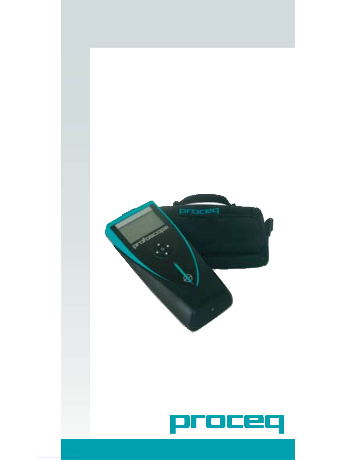
profoscope
www.proceq.com
...more than 50 years of know-how you can measure!
Operating Instructions
Rebar Detector
and Covermeter
Page 2
Getting Started
A start-up test kit is provided with the packaging to help
you familiarize yourself with the instrument.
i
First time user: Complete the tutorial OR see a
demo by a qualified Proceq representative.
1. Verify that there are no metal items on hands, fingers,
or in the vicinity of test area, (metal trolleys etc.)
2. Power on: Press the ON/OFF button on the top
panel.
3. Reset the instrument.
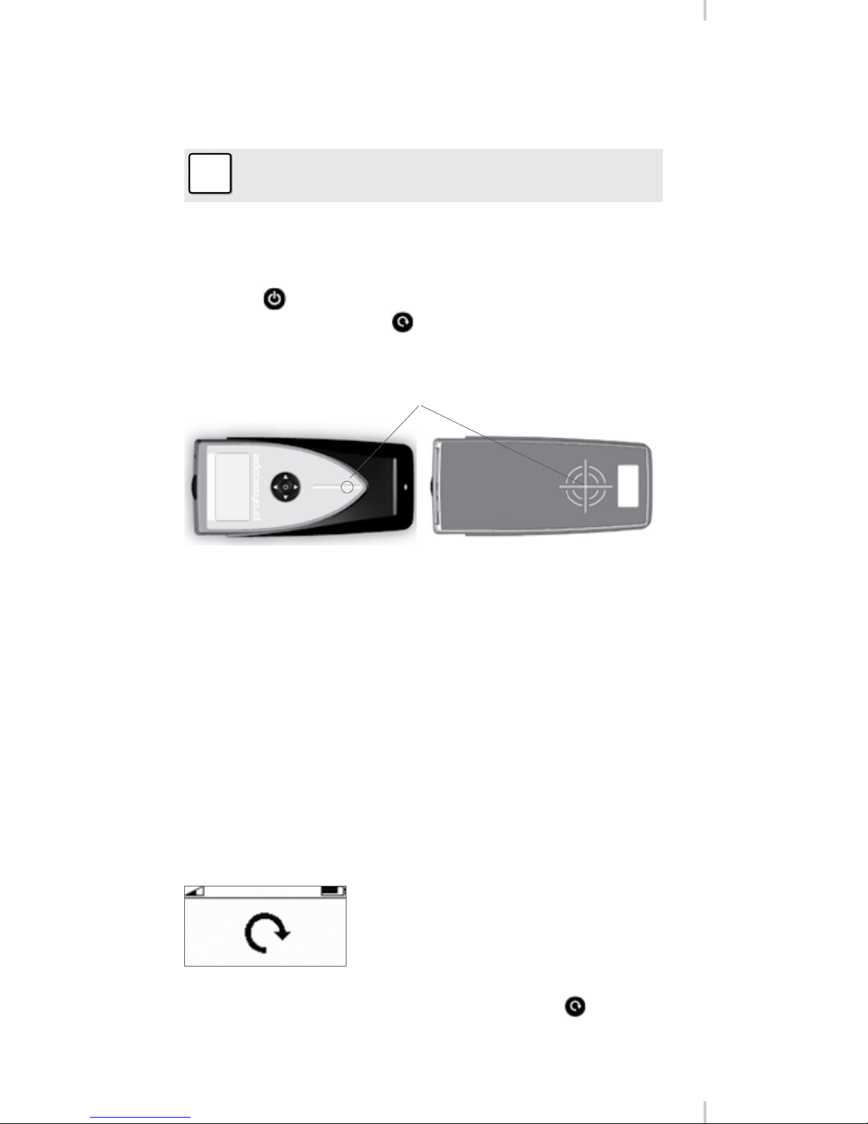
4. Check the location of the Measurement Center (MC)
which indicates the center of the probe.
MC
5. Check the operation with the start-up test kit and confirm:
- The location and orientation of the rebars
- The position between two rebars
- Cover depths 15mm / 0.59” and 60 mm / 2.36”
- Diameter 16 mm / #5
Congratulations! Your new Profoscope is fully operational
and you can now continue with your measurements.
Performing a Reset
The pulse induction measuring principle is liable to drift
with temperature and other external influences. Performing
a reset corrects for any drift and ensures accurate measurements. We recommend a reset every 5 minutes or so.
On power on, the Profoscope reminds the user to perform a reset.
Hold the Profoscope in free space (no metal within a
40cm / 16” sphere) and press the reset key. The display rotates for approximately 2.5s while the reset is carried out.
2 © 2008 by Proceq SA
Page 3

© 2008 by Proceq SA 5
Table of Contents
Getting Started 2
Overview of the Profoscope 3
The Profoscope Display 4
1 Safety and Liability 6
1.1 Safety and Usage Precautions 6
1.2 Liability 6
1.3 Safety Instructions 6
1.4 Labelling Used in the Manual 6
2 Tutorial 7
2.1 The Measurement Principle 7
2.2 The Measuring Range 8
2.3 Factors Affecting the Measurement 8
2.3.1 Errors due to Neighboring Bars 8
2.3.2 Resolution 9
2.3.3 Effect of Setting Incorrect Bar Diameter 10
2.3.4 Factors Affecting Diameter Determination 11
2.3.5 Orientation 11
3 Real Tests 12
3.1 Preparation 13
3.2 Locate a Rebar 13
3.2.1 Finding a Rebar 13
3.2.2 Check the Orientation 16
3.2.3 Verification 17
3.2.4 Locate a Mid Point 17
3.2.5 Map out the Rebar Grid 17
3.2.6 Advanced Settings (Measuring Range) 18
3.3 Measure Cover Depth 18
3.3.1 Set the Rebar Diameter 18
3.3.2 Read the Cover Depth 19
3.3.3 Advanced Settings (Neighboring Rebar Correction) 19
3.3.4 Advanced Settings (Minimum Cover Alert) 19
3.4 Measure Rebar Diameter 20
3.4.1 Determining Unknown Rebar Diameter 20
3.4.2 Create a Rebar Grid 20
3.4.3 Work with a Default Value 21
3.4.4 Drill Inspection Hole 21
4 General Settings 22
4.1 Navigating 22
4.2 Regional Setting 22
4.3 Bar Diameter 23
4.4 Measuring Range Selection 23
4.5 Audio Setting 24
4.6 Minimum Cover 24
4.7 Neighboring Bar Compensation 24
5 Technical Specifications 25
6 Part Numbers and Accessories 26
7 Maintenance and Support 27
7.1 Replacing the Protective Cover 27
7.2 Support Concept 27
Subject to change without notice.
820 39 101E ver 09 2008
Page 4
6 © 2008 by Proceq SA
1 Safety and Liability
1.1 Safety and Usage Precautions
This manual contains important information on the safety,
use and maintenance of the Profoscope. Read through
the manual carefully before the first use of the instrument.
Keep the manual in a safe place for future reference.
1.2 Liability
Our “General Terms and Conditions of Sale and Delivery”
apply in all cases. Warranty and liability claims arising from
personal injury and damage to property cannot be upheld
if they are due to one or more of the following causes:
Failure to use the instrument in accordance with its •
designated use as described in this manual.
• Incorrectperformancecheckforoperationandmaintenance of the instrument and its components.
• Failuretoadheretothesectionsofthemanualdealing
with the performance check, operation and maintenance of the instrument and its components.
• Unauthorized structural modications to the instrument and its components.
• Serious damage resulting from the effects of foreign
bodies, accidents, vandalism and force majeure.
All information contained in this documentation is presented in good faith and believed to be correct. Proceq
SA makes no warranties and excludes all liability as to the
completeness and/or accuracy of the information.
1.3 Safety Instructions
The instrument is not allowed to be operated by children
or anyone under the influence of alcohol, drugs or pharmaceutical preparations. Anyone who is not familiar with
this manual must be supervised when using the instrument.
1.4 Labelling Used in the Manual
i
Note: This symbol indicates important information.
Safety
Page 5
© 2008 by Proceq SA 7
2 Tutorial
2.1 The Measurement Principle
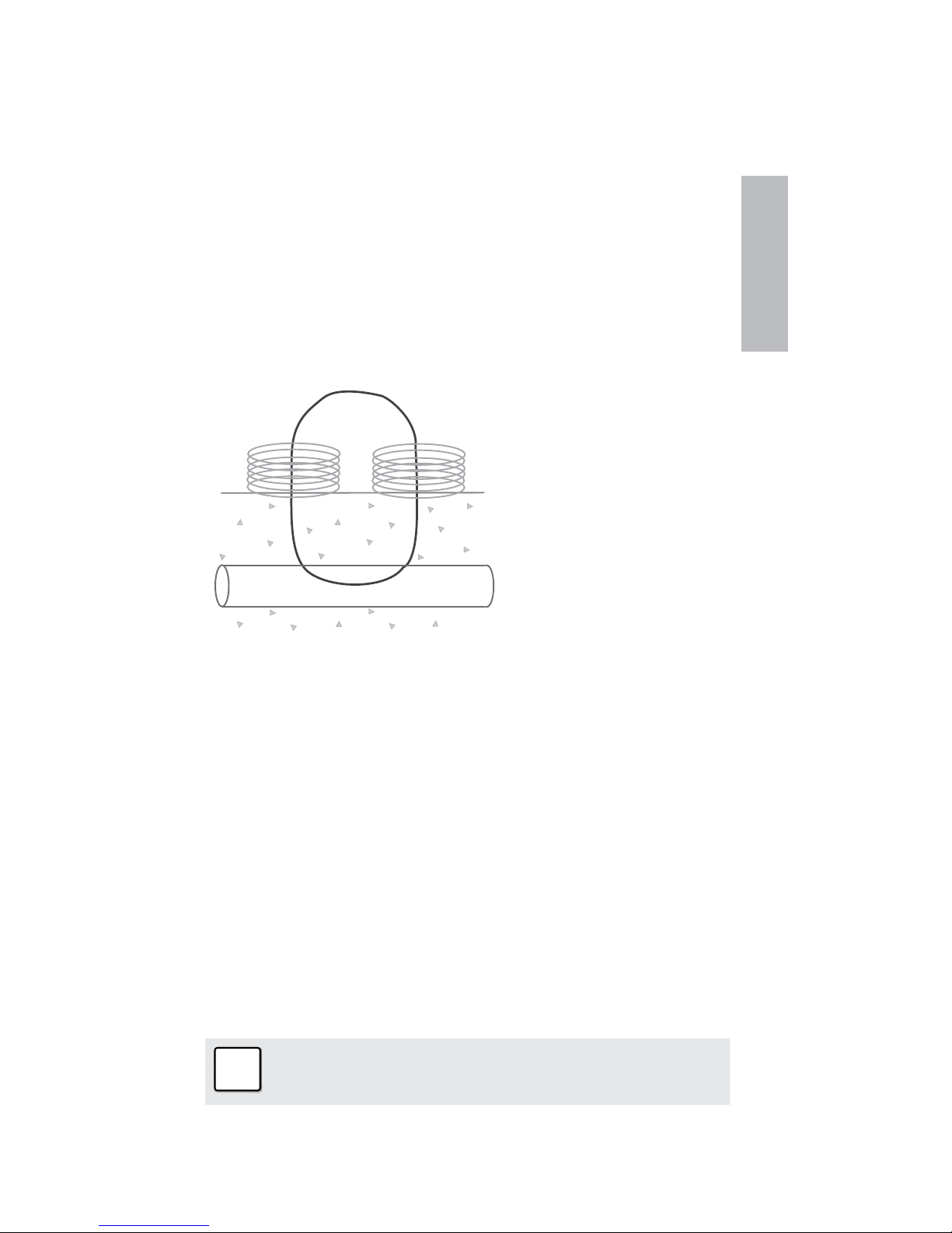
The Profoscope uses electromagnetic pulse induction
technology to detect rebars.
Coils in the probe are periodically charged by current
pulses and thus generate a magnetic field.
On the surface of any electrically conductive material
which is in the magnetic field eddy currents are produced.
They induce a magnetic field in opposite direction. The
resulting change in voltage can be utilized for the measurement.
Coils
Concrete Magnetic Field
Rebar
The Profoscope uses different coil arrangements to generate several magnetic fields. Advanced signal processing
allows
1. Localization of a rebar
2. Localization of the mid-point between rebars
3. Determination of the cover
4. Estimation of the bar diameter
This method is unaffected by all non conductive materials
such as concrete*, wood, plastics, bricks etc. However
any kind of conductive materials within the magnetic field
(approx. 400 mm / 16” sphere) will have an influence on
the measurement.
i
Note: Remove all metallic objects such as rings
and watches before you start measuring.
* Some concrete types and other structural materials may
have metallic content.
Tutorial
Page 6
8 © 2008 by Proceq SA
2.2 The Measuring Range
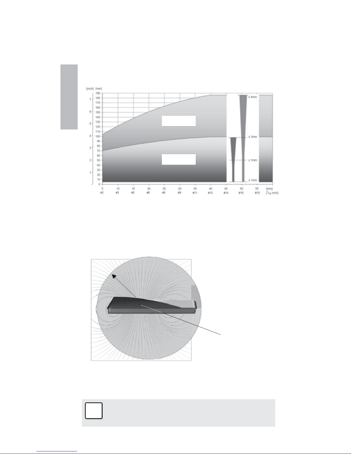
The pulse induction principle used by Profoscope has a
defined range of operation.
The measuring range is dependent on the bar size. The
expected accuracy of the cover measurement is indicated
in the graphic below. (Complies with BS1881 part 204, for
a single rebar with sufficient spacing).
long measuring
range
Cover depth
measuring accuracy
short measuring
range
Bar size
2.3 Factors Affecting the Measurement
2.3.1 Errors due to Neighboring Bars
All rebars within the sphere of influence affect the reading.
Sphere of influence
400 mm /16 inch
MC
Neighboring bars close to the target bar result in an underestimated cover value and an overestimated bar diameter.
i
Note: This effect can be reduced by the neighboring bar correction implemented in the Profoscope.
Tutorial
Page 7
© 2008 by Proceq SA 9
2.3.2 Resolution
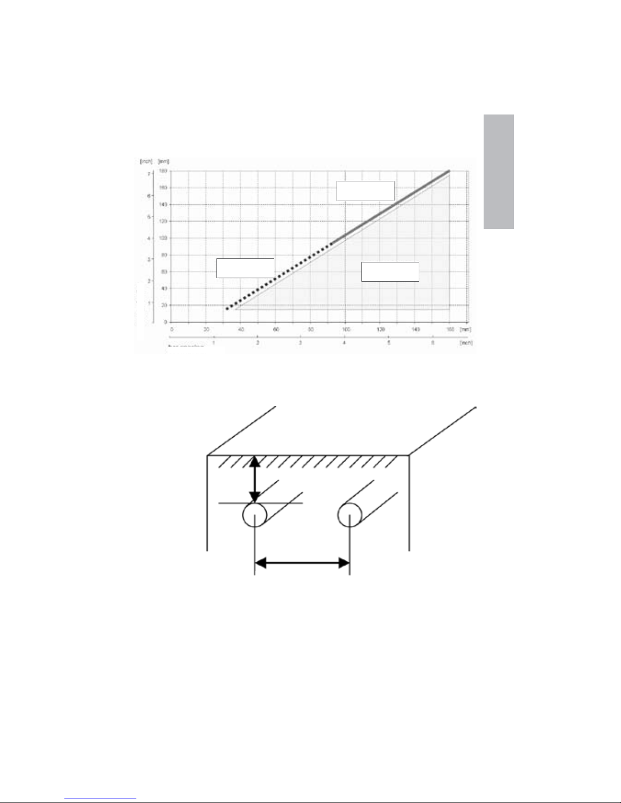
There is a limit on the minimum spacing of bars depending on the cover depth. It is impossible to distinguish between individual bars below these limits.
(For the depth at which bars of different sizes can be detected at all – see 2.2)
short measuring
range
Cover depth
Bar spacing
long measuring
range
rebars can be
separated
Cover
Bar spacing
Tutorial
Page 8
10 © 2008 by Proceq SA
2.3.3 Effect of Setting Incorrect Bar Diameter
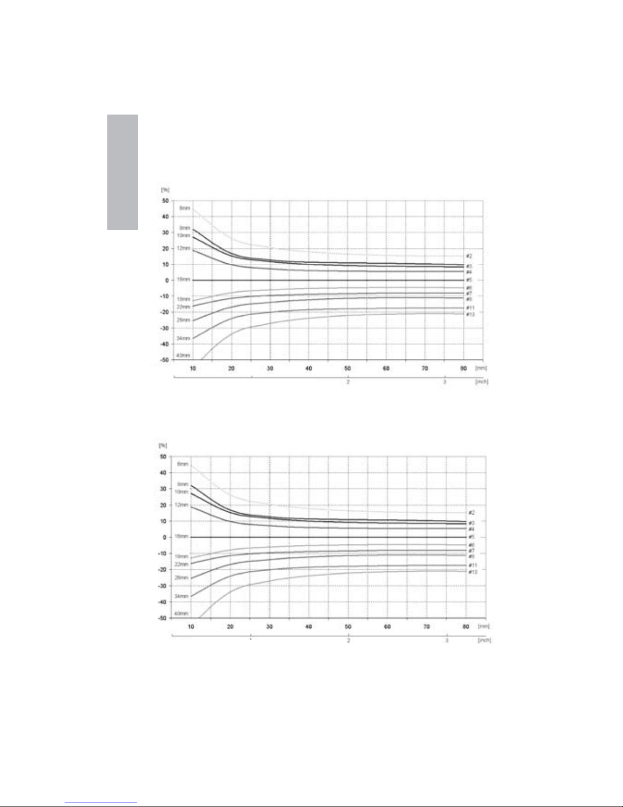
The accuracy of the cover measurement is also dependent on setting the correct bar diameter.
The following two charts give an estimation of the error in
percentage of the cover reading for different rebar sizes if
a default size of 16mm (#5) is set.
For the short range:
Cover depth
Error
For the long range:
Cover depth
Error
Tutorial
Page 9
© 2008 by Proceq SA 11
2.3.4 Factors Affecting Diameter Determination
Two factors affect the determination of the rebar diameter.
One is the cover depth. Diameter can be determined for
rebars with cover not exceeding 80% of the small range.
(64 mm, 2.5”)
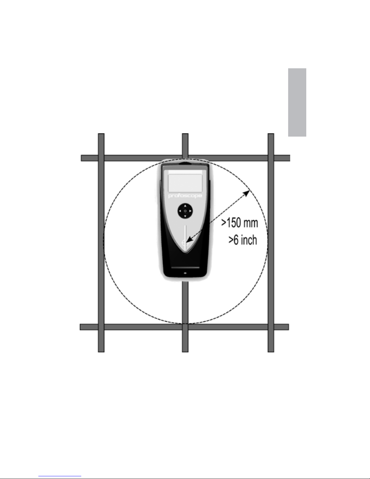
The second is the separation between neighboring bars.
The separation between the bars must be greater than the
limits shown in the drawing below (with reference to the
MC) for accurate determination of diameter.
2.3.5 Orientation
The strongest signal results when the center line of the
probe is parallel to a bar. The center line in the Profoscope
is the long axis of the instrument. This property is used to
help determine the orientation of the rebars.
Tutorial
Page 10
12 © 2008 by Proceq SA
3 Real Tests
Overview
Read the
Tutorial
Understanding the boundaries of the pulse induction principle
Complete
Getting Started
Check the operation of your Profoscope with
the start-up test kit
Regional Settings Change default settings to your regional standard
What Do You
Want to Do?
3.2
Locate a Rebar
No further
Settings necessary
Locate the Rebar
Check the
Orientation
Place center line directly over rebar•
3.3
Measure
Cover Depth
Key-in Rebar
Diameter
Place Center Line
Directly over Rebar
Read off Cover Depth
An accurate rebar diameter setting will •
give an accurate cover depth result
Activate neighboring bar correction if •
necessary
Create Rebar Grid
Check minimum bar spacing•
3.4
Measure Rebar
Diameter
Determining
Unknown Rebar
Diameter
Work with Default
Known error tolerances given in the •
Tutorial section
Drill Inspection Hole
Remove all doubt•
Real Tests
Page 11
© 2008 by Proceq SA 13
3.1 Preparation
See chapter 4 for advice on selecting your regional setting
and on navigating around the menus.
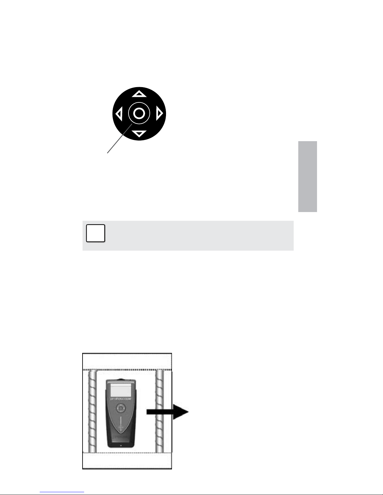
Measuring Screen Short Cuts
UP
RIGHT
DOWN
SELECT
LEFT
Pressing the up arrow
will switch the back-light
on/off.
Pressing the right arrow
toggles between measuring ranges.
3.2 Locate a Rebar
☺ Switch on the Profoscope and perform a reset as ex-
plained in “Getting Started”. The Profoscope can immediately be used to locate a rebar.
i
Note: The Profoscope is able to locate a rebar
and also the mid-point between two rebars. It is
important to be able to recognize which is which.
3.2.1 Finding a Rebar
Step 1 – Place the Profoscope on the test surface and
move it slowly in a chosen direction. The Profoscope reacts differently depending on its orientation relative to the
rebars. There are three scenarios.
Scenario A)
Sweeping Parallel to the Rebars
☺ Try it out on the start-
up test kit.
Real Tests
Page 12
14 © 2008 by Proceq SA
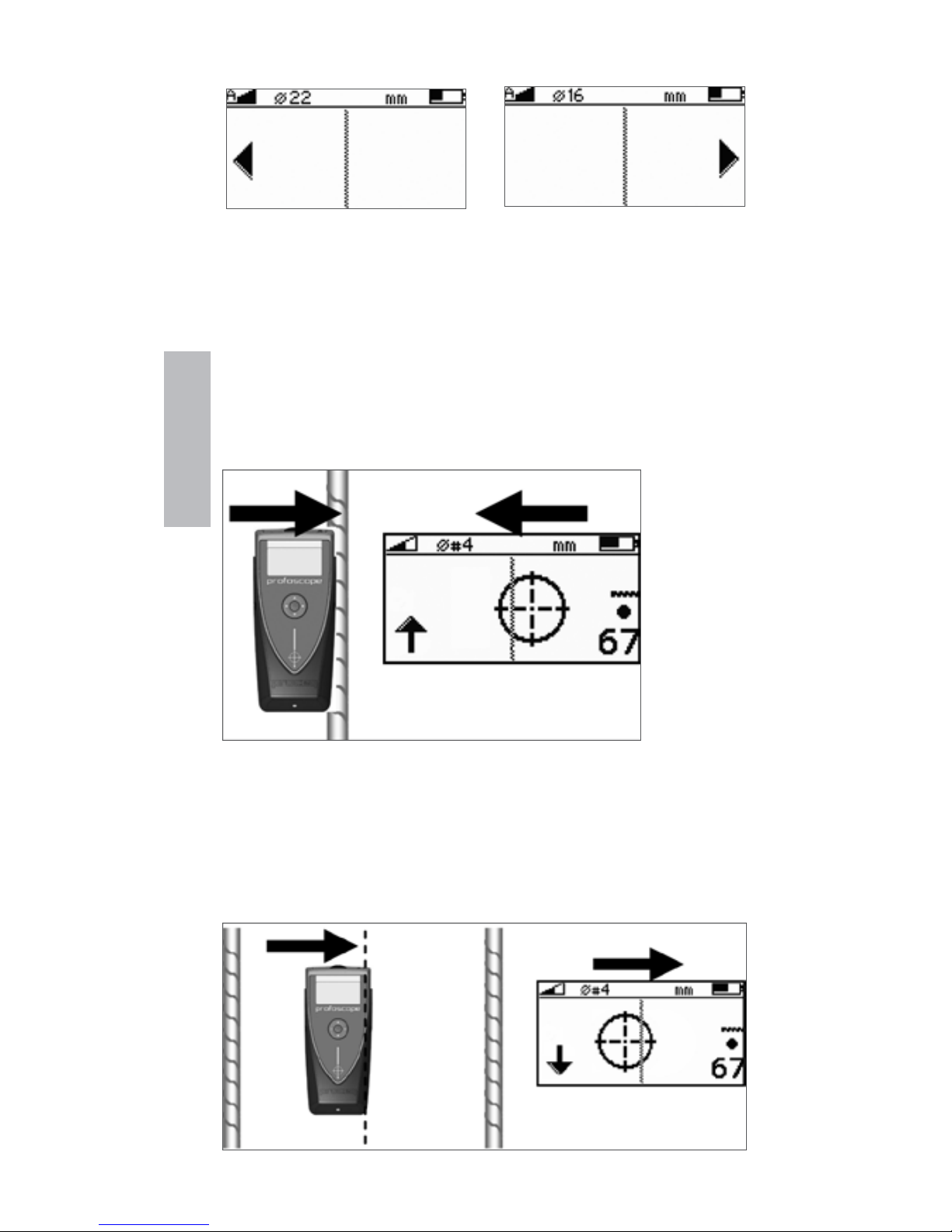
Arrows indicate proximity of rebars off screen.
Continue sweeping in the chosen direction.
As you get closer, the rifle scope indicates either:
The presence of a rebar beneath the instrument or,•
The mid-point between two rebars beneath the instru-•
ment.
It is very simple to differentiate between the two.
Approaching a Rebar
Rifle scope moves in opposite direction to the Profoscope.
The signal strength is increasing as the rifle scope
moves towards the center line.
Approaching a Mid-point
Real Tests
Page 13
© 2008 by Proceq SA 15
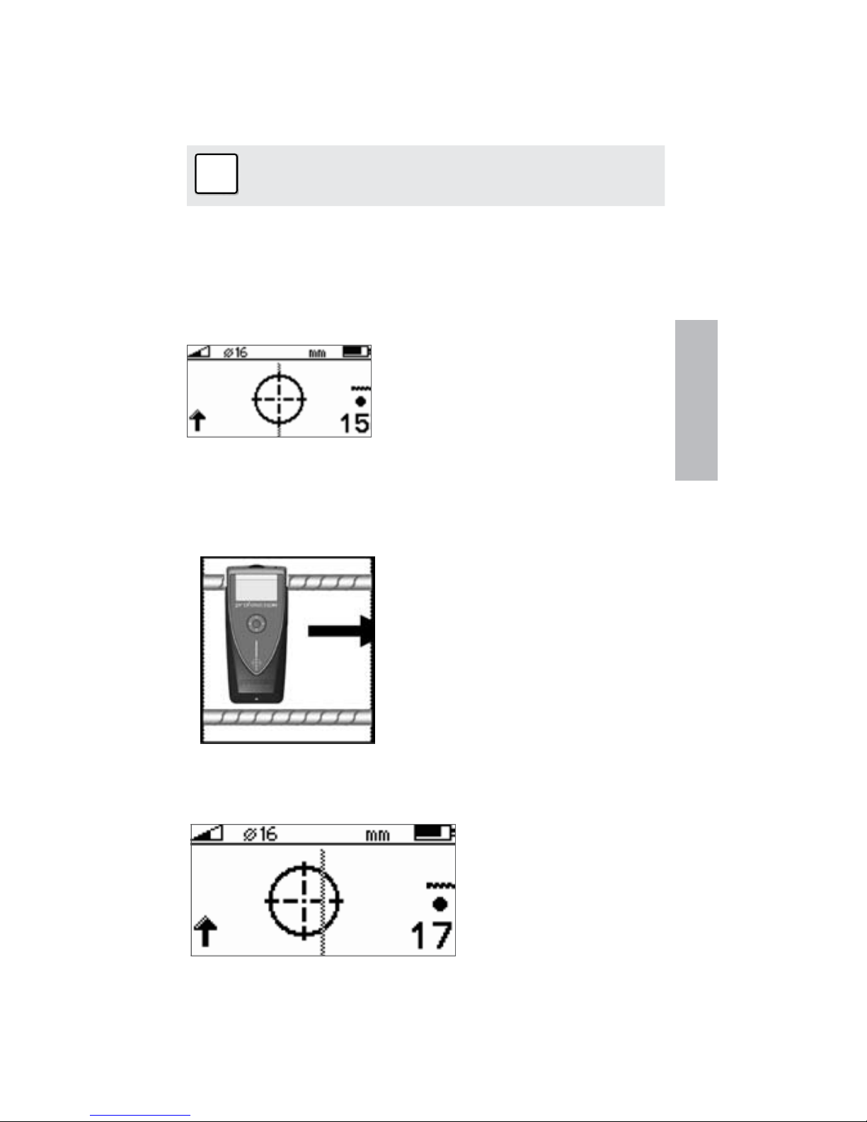
Rifle scope moves in the same direction as the Profoscope.
The signal strength is decreasing as the rifle scope
moves towards the center line.
i
Confirm that you are approaching a rebar.
Continue sweeping until the rifle scope is in the center of
the screen. When it is centered exactly, the LED indicator
will light. (If the acoustic signal is activated it will sound
as long as the LED is lit). The rebar is directly beneath the
measurement center.
Rebar centered
Scenario B)
Sweeping Perpendicular to the Rebars
☺ Try it out on the start-
up test kit.
If there are rebars within range, the rifle scope will remain
close to the center of the screen and move very little.
Little or no movement of
the rifle scope.
In this case turn the Profoscope by 90° and continue
sweeping as described in the previous section.
Real Tests
Page 14
16 © 2008 by Proceq SA
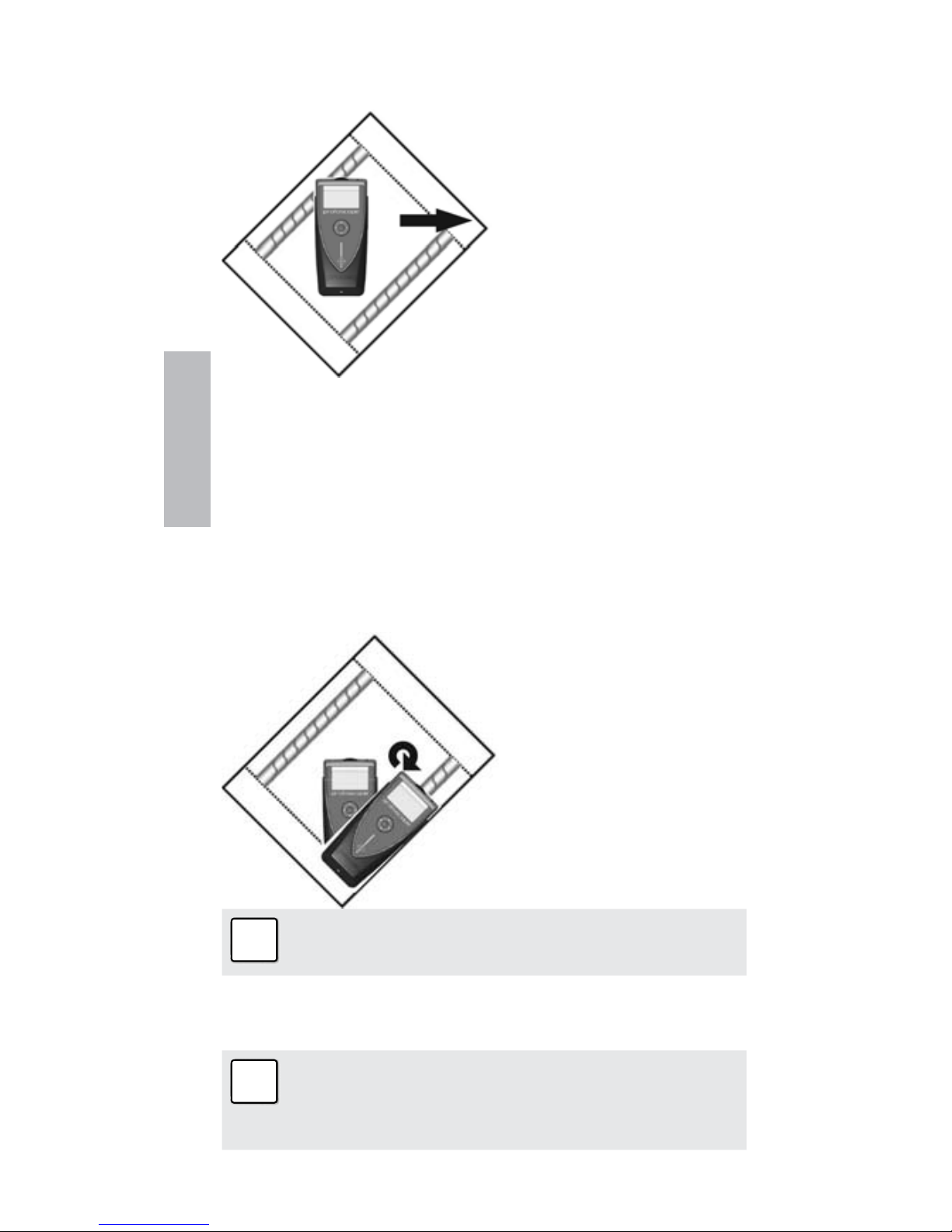
Scenario C)
Sweeping at an Angle to the Rebars
☺ Try it out on the start-
up test kit.
The response on the screen will be similar to the case
when you are sweeping parallel, but the movement of the
rifle scope will be slower.
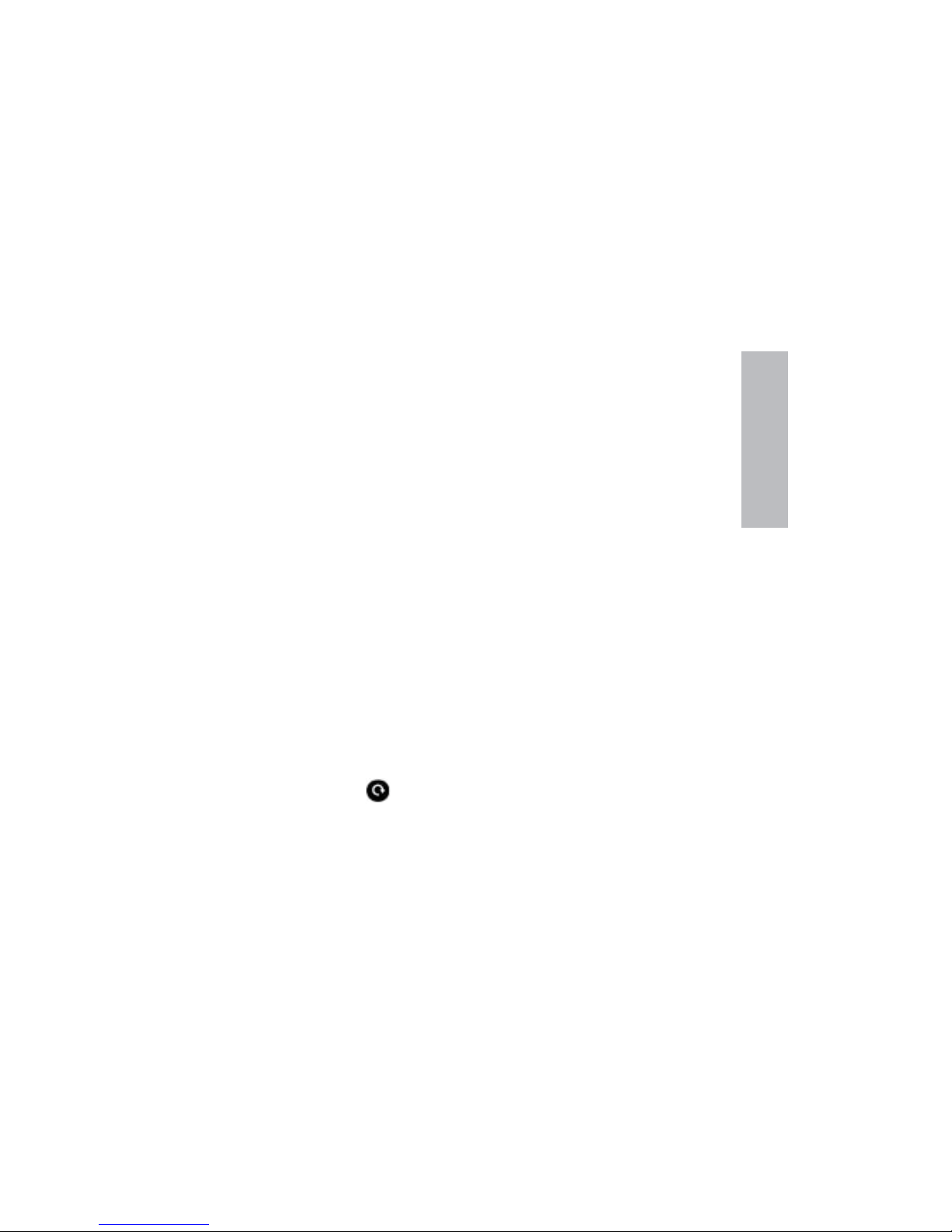
3.2.2 Check the Orientation
Step 2 – Once you have located the rebar, you need to
check the orientation of the bar by rotating around the
measurement center.
☺ Try it out on the start-
up test kit.
i
Note: Ensure that the rifle scope remains centered as you rotate.
Rotate until you get the minimum cover value and the LED
indicator is lit.
i
Note: The signal strength arrow can also be
used as an aid here. The signal strength will increase as you rotate towards the correct orientation and decrease as rotate away.
Real Tests
Page 15
© 2008 by Proceq SA 17
The center line of the Profoscope is now directly above
the rebar and pointing in the same direction. Mark at either
end of the instrument with chalk or similar.
3.2.3 Verification
Step 3 – Verify by moving the Profoscope in the direction
of the rebar and observe that the cover depth reading displays a constant value.
3.2.4 Locate a Mid Point
Step 4 – Continue sweeping with the center line of the
Profoscope parallel to the rebar you have just located. As
you approach the mid-point between two rebars the rifle
scope will appear on the screen again. This time:
• Theriescopewillmoveinthesamedirectionasthe
Profoscope.
• The signal strength will be decreasing as the rifle
scope moves towards the center line.
Center the rifle scope as described previously to locate
the exact position of the mid point.
☺ You may want to mark the mid-points as well as a
guide to drilling holes.
3.2.5 Map out the Rebar Grid
Step 5 – “Reset” the Profoscope again and then start
the process once more to locate further rebars.
Sweep in one direction first and then at 90° to build up
the grid.
You will soon have a good representation the rebar configuration to help you begin drilling or to conduct further
measurements of cover depth and rebar diameter and so
forth.
Real Tests
Page 16
18 © 2008 by Proceq SA
3.2.6 Advanced Settings (Measuring Range)
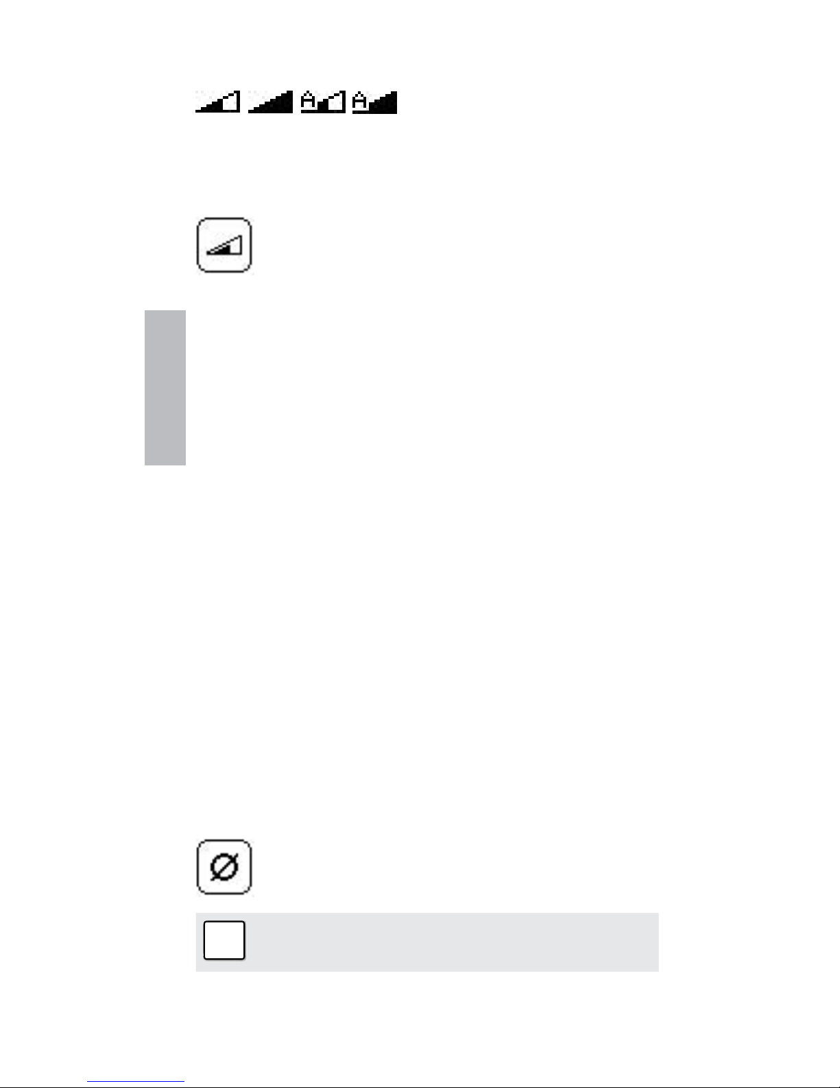
short, long, auto, auto
This symbol in the top left corner of the screen indicates
the measuring range set. Toggle between ranges with the
short cut describe in chapter 3.1.
The range can also be set in the main menu by
selecting the following icon.
Choose the short range to accurately detect rebars that
are embedded closer to the concrete surface.
The long range setting will allow rebars embedded deeper
in the concrete structure to be detected. However, it will
create a larger sphere of influence which in turn means
that neighboring rebars may affect the reading.
Alternatively, choose the automatic setting that will automatically toggle between the short range and the long
range.
3.3 Measure Cover Depth
Once the rebar grid has been located the cover can be
measured.
3.3.1 Set the Rebar Diameter
☺ An accurate knowledge of the rebar diameter will also
give best cover depth results.
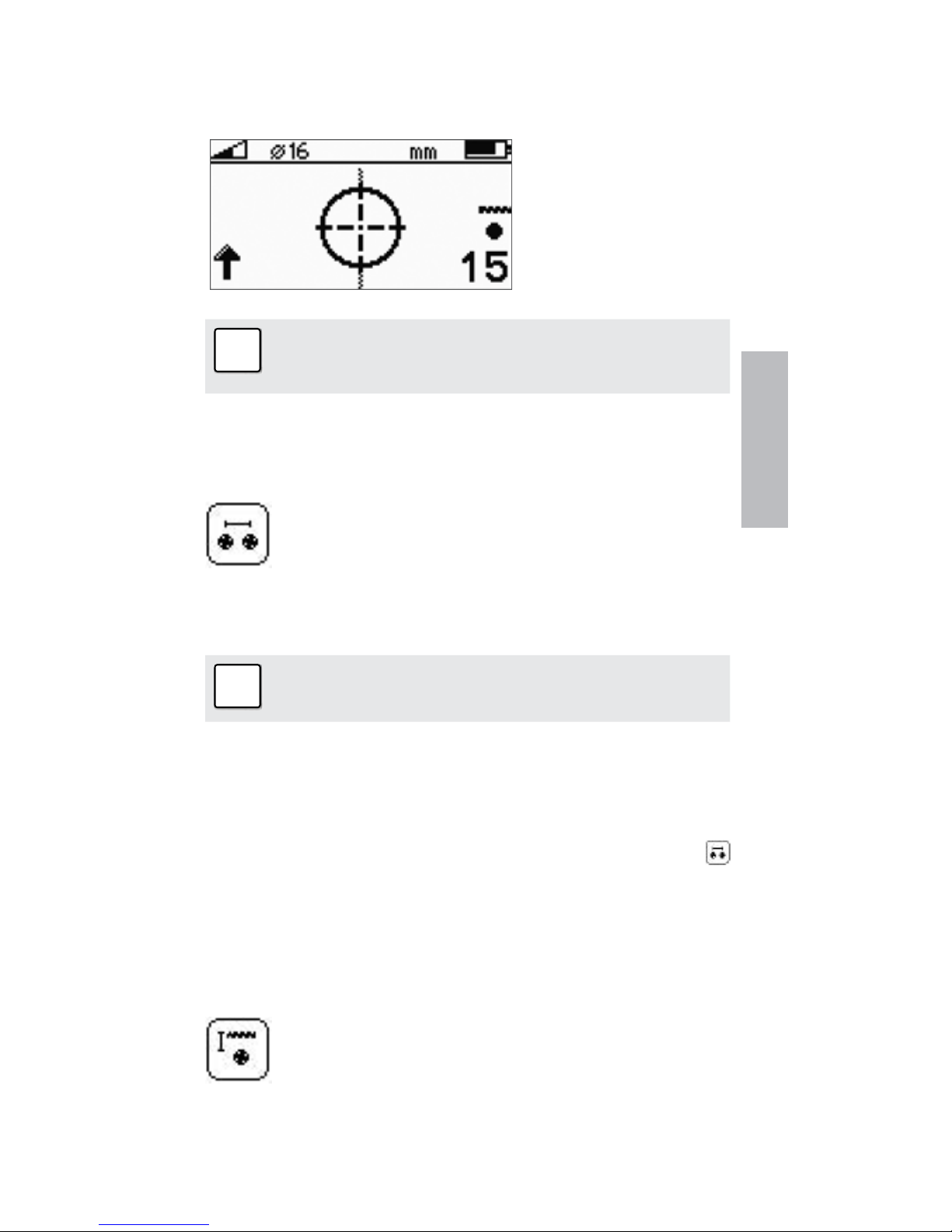
The default reference rebar diameter set in the instrument
is 16 mm or #5. This can be seen in the status row at the
top of the display screen.
Step 1 - If you already know the actual rebar diameter, select the icon in the menu to set this as
the reference.
i
Note: If you DO NOT know the rebar diameter,
then proceed to chapter 3.4.
Real Tests
Page 17
© 2008 by Proceq SA 19
3.3.2 Read the Cover Depth
Step 2 - Place the centre line of the Profoscope directly
over the rebar and read off the cover depth.
e.g.
Cover depth = 15 mm
i
Note: Ensure that the measurement centre is not
placed over a horizontal/vertical intersection in
the rebar grid.
3.3.3 Advanced Settings
(Neighboring Rebar Correction)
As described in the tutorial neighboring rebars
that are within the sphere of influence will also be
detected by the Profoscope and will affect cover
depth results. The effects of neighboring rebars can be
mitigated by keying-in a correction value.
i
Note: This works for rebars of the same layer running in parallel to the rebar under test.
Measure the distance from the rebar under test to a
neighboring rebar. (See 3.2.5)
Enter the settings menu, select the icon and input this
value. Verify that neighboring rebar correction symbol
is active in the status line at the top of the display. Repeat
step 2.
3.3.4 Advanced Settings
(Minimum Cover Alert)
This is particularly useful for detecting insuffi-
cient concrete cover depth when conducting
large scale checks on structures after removing
the formwork or large scale building inspections and so
forth.
Real Tests
Page 18
20 © 2008 by Proceq SA
Enter the settings menu, select the icon and set the required cover depth limit. Verify that minimum cover alert
symbol is active in the status line at the top of the
display.
Move the Profoscope over the test surface. Whenever the
cover depth is less than the programmed minimum the
LED indicator will light and if it is enabled, an acoustic
alarm will be given.
i
Note: In this mode the LED will not light to indicate that a rebar has been located.
3.4 Measure Rebar Diameter
3.4.1 Determining Unknown Rebar Diameter
☺ The Chapter “Getting Started” shows that under the
right conditions the Profoscope can accurately determine the diameter of a rebar.
The Tutorial chapter on the pulse induction principle describes the limitations of the technology and clearly outlines the conditions whereby accurate readings of rebar
diameter CANNOT be made if there is too much interference from neighboring rebars or other metallic objects
within the sphere of influence.
We present 3 working methods which are recommended
to obtain the best results.
3.4.2 Create a Rebar Grid
Method 1 To map out a rebar grid on a test surface and
then to select one rebar from the grid that has sufficient
spacing from other rebars.
Step 1 - Create a rebar grid as described in chapter
3.2.5.
Step 2 - Select one rebar that has the largest spacing
from neighboring rebars.
Step 3 - Use a ruler and confirm that the spacing is at
least 150 mm (6”). If not, redo Steps 1 and 2 until a rebar
Real Tests
Page 19
© 2008 by Proceq SA 21
is located with at least 150 mm (6”) spacing to a neighboring rebar.
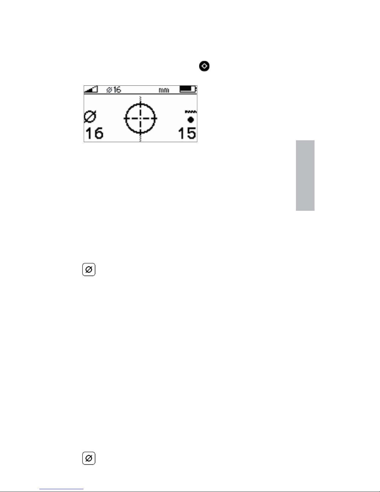
Step 4 - Place the centre line of the Profoscope over the
rebar and click the function key on the left side.
The measured rebar
diameter replaces the
signal strength arrow.
Note down the rebar diameter.
☺ Try it out on the start-up test kit.
3.4.3 Work with a Default Value
Method 2 The purpose of this approach is to work with
a default value with known error tolerances.
From the menu item “Bar diameter” select the default
value 16mm or #5 for the diameter.
Use the chart in section 2.5 of the tutorial to understand
the errors that can be expected in the cover readings if the
actual rebar diameters differ from the reference value.
3.4.4 Drill Inspection Hole
Method 3 The purpose of this approach is to accurately
determine the rebar diameter through destructive means.
If neither of the methods 1 and 2 are feasible for whatever reason and you are still in doubt (this could be the
case when rebars are bunched too close together or are
too small in diameter), then drill an inspection hole wide
enough to allow the use of a caliper to measure the rebar diameter. Program this value into the Profoscope and
proceed.
Real Tests
Page 20
22 © 2008 by Proceq SA
4 General Settings
4.1 Navigating
UP
RIGHT
DOWN
SELECT
LEFT
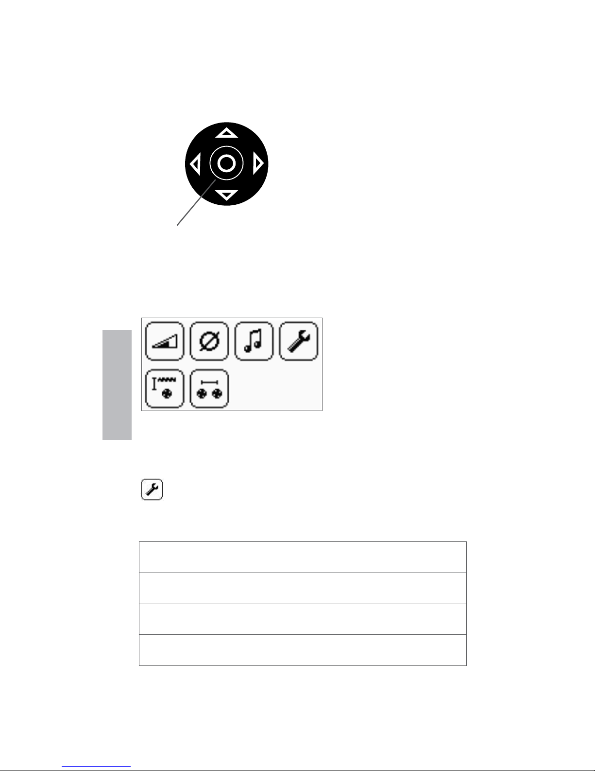
The settings menu can
be entered by pressing
the select button. Use
the navigation keys to
select the desired menu
icon and press the select button again.
Scroll within the menus to the setting you wish to make
and press the select button to implement it. Exit the main
menu by pressing either the reset or function button.
Each menu item is described in detail below.
4.2 Regional Setting
The Profoscope supports 4 regional settings. This
setting affects all other displays and should be
done prior to making other selections.
Metric
Cover and bar diameters in mm according to table in 4.3
ASTM inch
Cover in inch, bar diameters according
to table in 4.3
ASTM mm
Cover in mm, bar diameters according
to table in 4.3
Japanese
Cover in mm, bar diameters according
to table in 4.3
General Settings
Page 21
© 2008 by Proceq SA 23
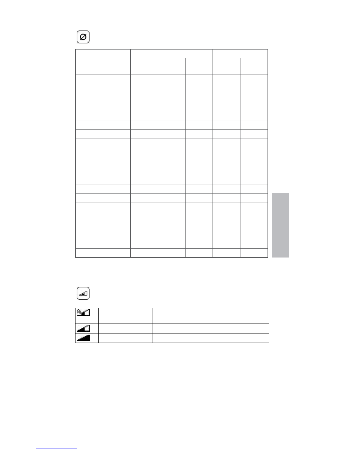
4.3 Bar Diameter
Based on the regional setting, the bar diameter
menu supports following bar dimensions.
Metric ASTM Japanese
Bar
size
Diam.
(mm)
Bar
size
Diam.
(inch)
Diam.
(mm)
Bar
size
Diam.
(mm)
5 5 #2 0.250 6 6 6
6 6 #3 0.375 10 9 9
7 7 #4 0.500 13 10 10
8 8 #5 0.625 16 13 13
9 9 #6 0.750 19 16 16
10 10 #7 0.875 22 19 19
11 11 #8 1.000 25 22 22
12 12 #9 1.125 29 25 25
14 14 #10 1.250 32 29 29
16 16 #11 1.375 35 32 32
18 18 #12 1.500 38 35 35
20 20 #13 1.625 41 38 38
22 22 #14 1.750 44 41 41
25 25 #15 1.875 48 44 44
28 28 #16 2.000 51 48 48
32 32 #18 2.250 57 51 51
36 36 57 57
40 40
44 44
50 50
4.4 Measuring Range Selection
Select according to the depth of the rebars. Whenever possible, choose the short range.
Auto
Automatic switch from short to long if
no signal in short range
Short
< 80 mm < 3 inch
Long
< 180 mm < 7 inch
General Settings
Page 22
24 © 2008 by Proceq SA
4.5 Audio Setting
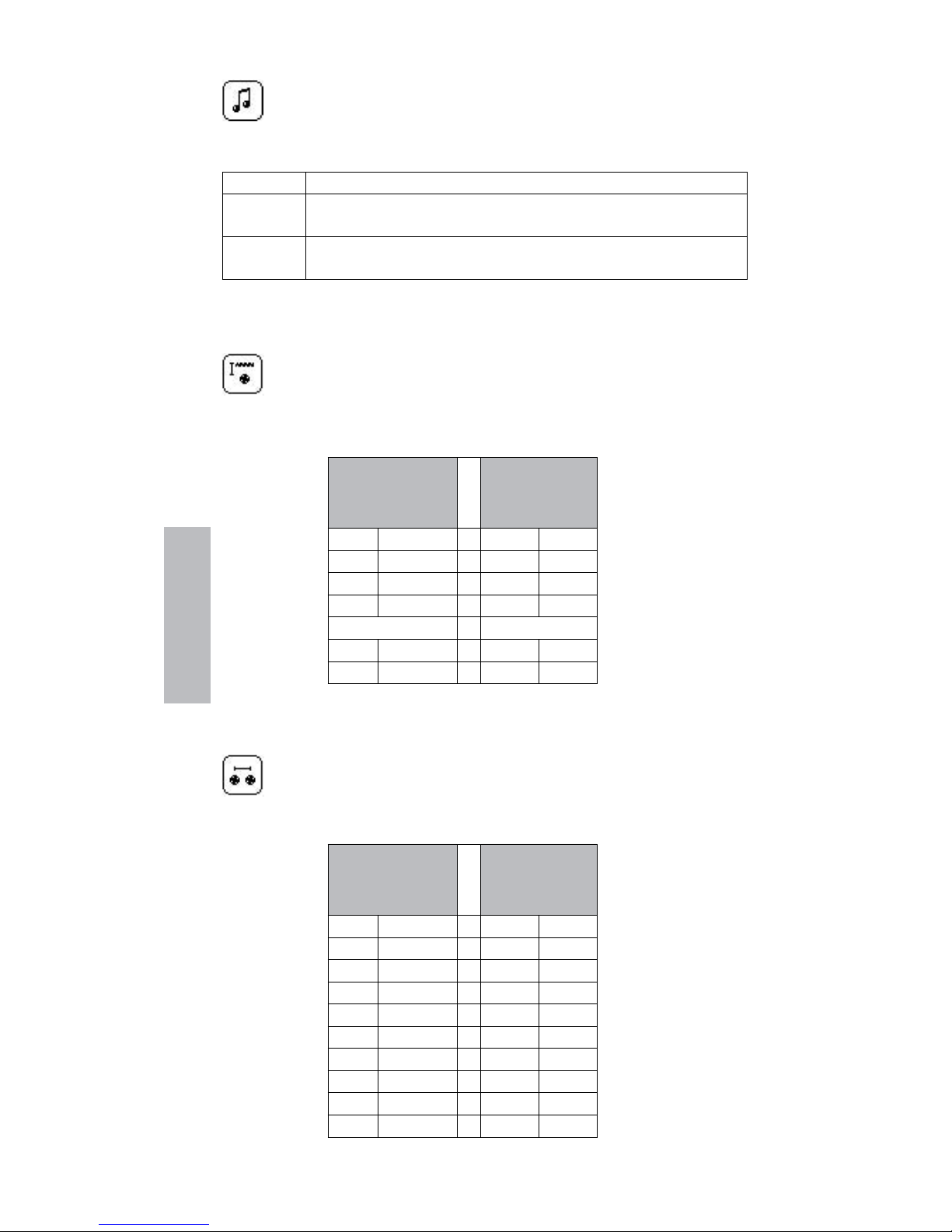
The device can give an audible tone when a key is
pressed, to assist in location or to give an alarm
when minimum cover alert is activated.
- No audio signals, silent
Centre Key pressed. Tone when rebar is centered. Minimum
cover alert.
Locate Key pressed. Increasing tone as approaching rebar.
Minimum cover alert.
4.6 Minimum Cover
If a minimum cover is selected, the LED is lit when
the cover is below this limit. If audio is on, an audio
signal is given.
Metric,
ASTM mm,
Japanese
ASTM
inch
- mm - inch
5 mm 0.20 inch
6 mm 0.24 inch
7 mm 0.28 inch
... ...
179 mm 7.04 inch
180 mm 7.08 inch
4.7 Neighboring Bar Compensation
Cover and bar diameter measurements are influenced by neighboring bars. This can be compen-
sated by selecting the bar spacing.
Metric,
ASTM mm,
Japanese
ASTM
inch
- mm - inch
50 mm 2.0 inch
60 mm 2.4 inch
70 mm 2.8 inch
80 mm 3.2 inch
90 mm 3.6 inch
100 mm 4.0 inch
110 mm 4.4 inch
120 mm 4.8 inch
130 mm 5.2 inch
General Settings
Page 23
© 2008 by Proceq SA 25
5 Technical Specifications
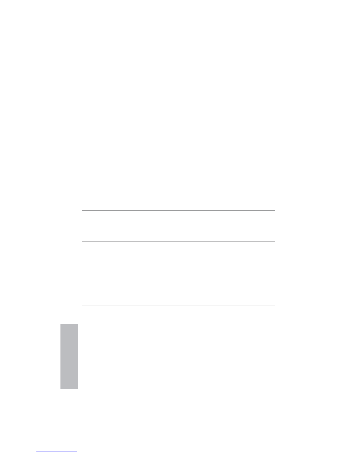
Power supply
Power source 2 x 1.5 V AA (LR6) batteries
Voltage range 3.6 V to 1.8 V
Current Consumption
Power on, backlight off ~ 50 mA
Power on, backlight on ~ 200 mA
Sleep mode ~ 10 mA
Power off < 1 μA
Battery Lifetime
Backlight off > 50 h
Backlight on > 15 h
Time Outs
Sleep mode 30 s
Auto shut down 120 s
Environmental Conditions
Temperature range -10º to 60º C (14º to 140º F)
Humidity range 0 to 100% rH
IP classification IP54
Conformity
CE, RoHS and WEEE
Standards and Regulations Applied
BS 1881 part 204
DIN1045
SN 505 262
DGZfP B2 (recommendation)
Technical Specs
Page 24
26 © 2008 by Proceq SA
6 Part Numbers and Accessories
Part Number Item
391 10 000 Profoscope unit consisting of:
Profoscope incl. standard accessories
(Packaging with integrated start-up
test kit, batteries, canvas bag, carrying
strap, chalk and product documentation).
Standard Accessories Delivered with the
Profoscope
391 80 100 Canvas bag
350 74 025 Battery type AA
391 80 110 Carrying strap
Optional Accessories
391 10 121S Self-adhesive protection covers
(Set of 3)
390 00 270 Calibration test block
391 80 140 Integrated sliding caliper and flush pin
gauge
325 34 018S Chalk (Set of 10)
Extended Warranty
391 88 001 Additional 1-year warranty *
391 88 002 Additional 2-year warranty *
391 88 003 Additional 3-year warranty *
* An extended warranty of one, two or three years for
be purchased at time of order or within 90 days thereafter.
Standard Warranty:
•Electronicportionoftheinstrument:24months
•Mechanicalportionoftheinstrument:6months
Part Numbers
Page 25

© 2008 by Proceq SA 27
7 Maintenance and Support
7.1 Replacing the Protective Cover
During normal operation on site, the base of the instrument glides across rough surfaces. In order to prevent
abrasion the instrument is protected by a self-adhesive
protective cover. It is recommended to check and replace
this cover periodically.
7.2 Support Concept
Proceq is committed to providing a complete support
service for this instrument. It is recommended that the
user register the product on the www.proceq.com to obtain valuable information on available updates and other
useful information.
Maintenance
Page 26

28 © 2008 by Proceq SA
Page 27
3 © 2008 by Proceq SA
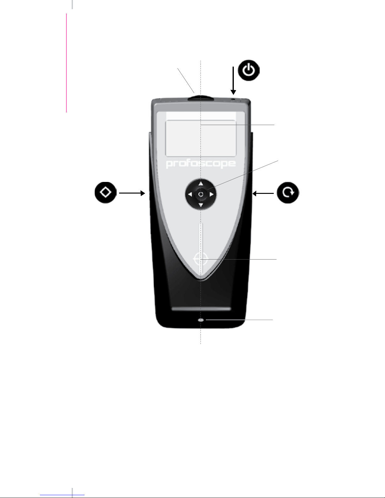
Overview of the Profoscope
1
2
4
5
7
9
8
6
3
1 Display 5 LED indicator
2 Navigation 6 Function key
3 Reset key 7 On/Off button
4 Measurement center 8 Battery compartment
9 Center line
Page 28
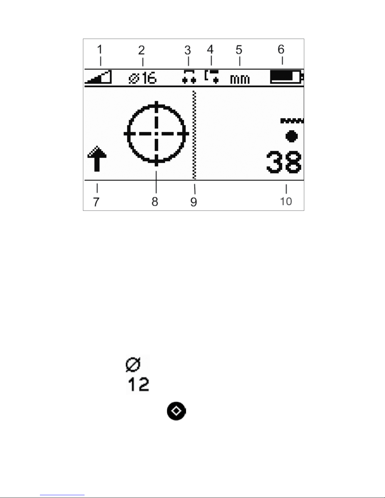
4 © 2008 by Proceq SA
The Profoscope Display
1 Measuring range (short, long, auto)
2 Reference rebar diameter
3 Neighboring rebar correction active
4 Minimum cover alert active
5 Measuring unit
6 Battery status
7 Signal strength (increasing / decreasing)*
8 Rifle scope
9 Center line
10 Measured cover depth
* The signal strength arrow is replaced by the measured
bar diameter:
e.g.
when the function key for bar diameter is pressed.
Page 29

Page 30

Made in Switzerland
Proceq Europe
Proceq USA, Inc.
117 Corporation Drive
Aliquippa, PA 15001
Phone +1-724-512-0330
Fax +1-724-512-0331
[email protected]
Proceq Asia Pte Ltd
12 New Industrial Road
#02-02A Morningstar Centre
Singapore 536202
Phone +65-6382-3966
Fax +65-6382-3307
[email protected]
Proceq Rus LLC
Ul.Optikov 4
korp.2, lit. A, office 321
197374 St. Petersburg
Russia
Phone/Fax + 7 812 448 35 00
[email protected]
Proceq Middle East
P.O. Box: 262419
Jebel Ali Free Zone
Dubai, United Arab Emirates
Phone +971 4 8865877
[email protected]
Proceq SAO Ltd.
South American Operations
Rua Haddock Lobo, 746 - 5 andar
Cerqueira Cesar, São Paulo
Brasil Cep. 01414-000
Phone +55 11 3083 38 89
[email protected]
Proceq Asia Pte Ltd Shanghai Rep Office
Room 1402, Unicom International Tower
No. 547, Tian Mu Road West
Shanghai, P.R.C 200070
Phone +86 21 6317 7479
[email protected]
www.proceq.com
 Loading...