

Page 1
WARNING:To reduce
the risk of serious injury, read these
warnings before using the scooter.
1. Read and follow all instructions.
2. It is the owner’s responsibility to
ensure that all users of the scooter
are adequately informed of all
warnings and instructions.
3. Inspect the scooter and tighten or
replace any loose or missing parts
before each use. In addition, make
sure that the lock pin is locked into
position, the handles and the stem
are securely locked in position, the
wheels rotate freely, the brake is in
working order and free of all debris,
and the wheel bolts are secure.
4. The scooter should not be used by
children under the age of eight. A
responsible adult must always
supervise young riders.
5. Always wear protective equipment,
including a helmet, knee pads, wrist
guards, elbow pads, and closed-toed
shoes, when using the scooter.
6. Never ride on streets, roadways, or
driveways that enter vehicle traffic
routes. Never ride on wet or uneven
surfaces, at night, or when visibility
is poor.
7. Never tow a rider with a bicycle,
motorcycle, or vehicle.
8. Locate the warning decals on the
scooter, and read the warnings
before using the scooter.
9. Save this User’s Manual for future
reference.
10. This scooter should not be used by
persons weighing more than 200
pounds.
11. Braking from high speeds or prolonged braking on inclines can cause
excessive wear of the rear wheel and
brake. Exercise caution when selecting your area of use.
12. To prevent burns, avoid touching the
brake after prolonged use.
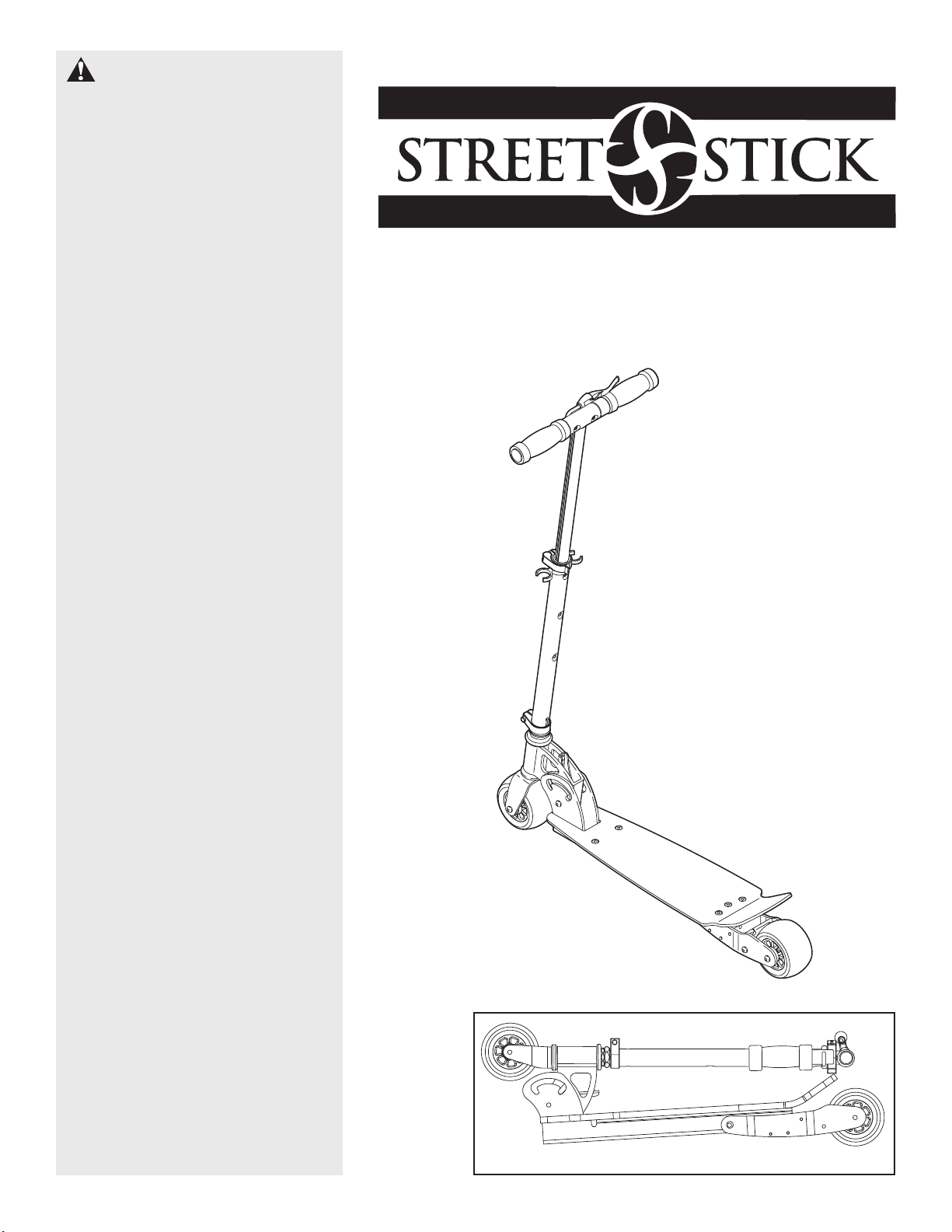
User’s Manual
Model No. PFSC09990
Page 2
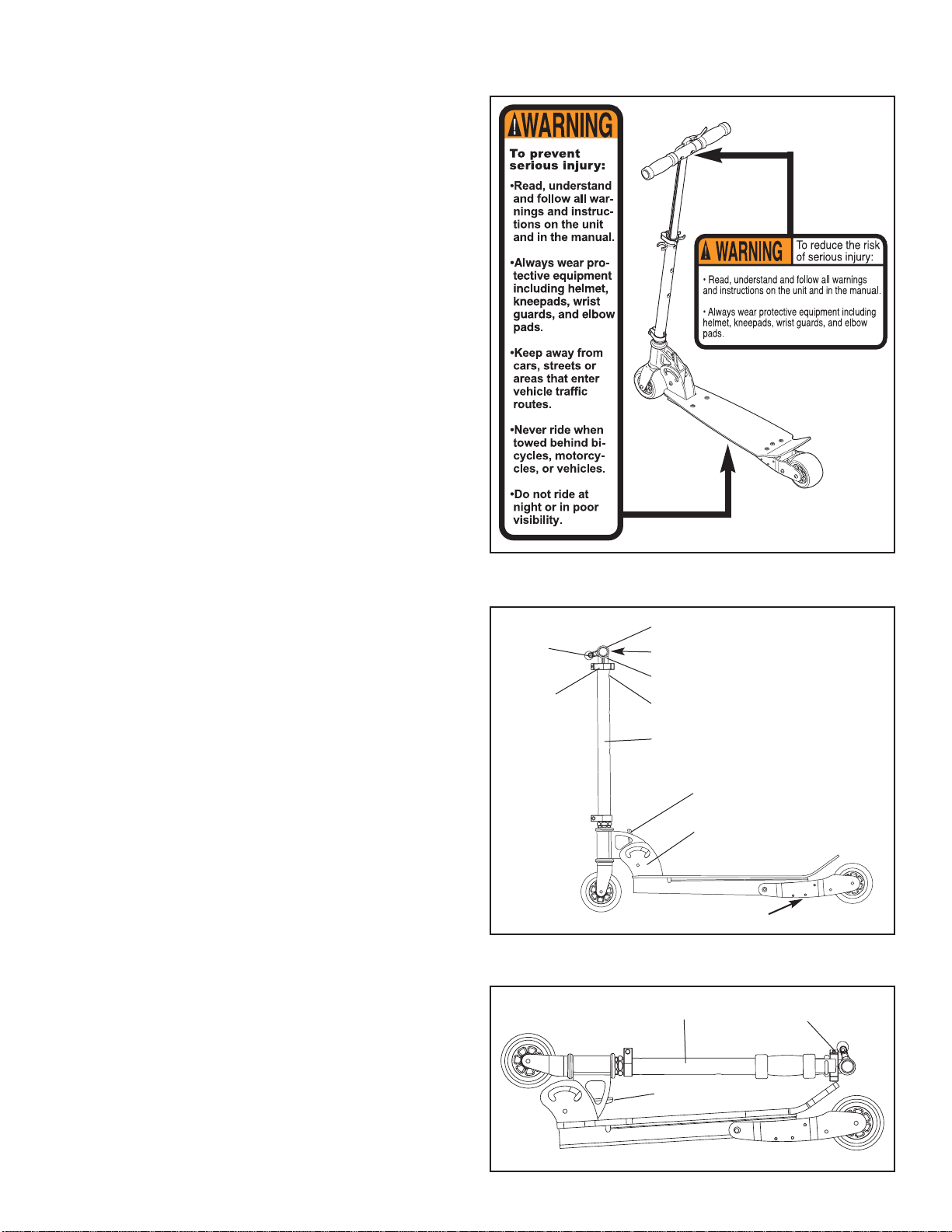
Warning Decal Placement
Setup
The decals shown at the right have been placed on the
scooter. If a decal is missing or illegible, please call our
Customer Service Department toll-free at 1-800-999-3756,
Monday through Friday, 6 a.m. until 6 p.m. Mountain
Time, to order a free replacement decal. Apply the replacement decal in the location shown.
Storage
1. Open the quick-release lever. Depress the push pin on the
stem and slide the stem down into the upright. Close the
quick-release lever.
2. Depress the push pins and remove the handles from the
stem. Press the handles into the storage clip on the upright.
3. Pull the thumb tab and pivot the upright down until it locks
in the horizontal position.
Before using the scooter, make sure that the scooter is set up
as described and that all parts are securely tightened.
1. Firmly press the thumb tab and pivot the upright up until it
locks in a nearly vertical position.
2. Insert the handles into the stem until the push pins are visi-
ble in the holes in the stem.
3. Open the quick-release lever. Depress the push pin on the
stem, and slide the stem up until the push pin is visible in
one of the three holes in the upright. With the stem at the
desired height, close the quick-release lever so that it is
snug against the upright. If the quick release is not snug,
see ADJUSTING THE QUICK RELEASE on the next
page.
Thumb Tab
Thumb Tab
Storage Clip
Brake
Stem
Quick
Release
Head Frame
Handle
Hand
Brake
Upright
Push Pins
Push Pin
Upright
Page 3

Adjusting The Quick Release
If the quick release doesn’t hold the stem snug in place, you
will need to adjust it.
Open the quick-release lever. Turn the adjustment nut clockwise
one half turn while keeping the lever from turning. Close the
lever. Repeat this procedure until the stem is held snug in place.
If the quick release is too snug to close, it will need to be
adjusted.
While the quick-release lever is open, turn the adjustment nut
counterclockwise one quarter turn while keeping the lever from
turning. Close the lever. Repeat this procedure until the stem is
held snug in place and the quick release is closed.
Adjustment
Nut
Open
Close
Lever
Quick Release
Hand Brake Maintenance
Refer to inset drawing 1. Locate the adjustment barrel (B) and
the lock nut (A) on the hand brake. Turn the lock nut (A) counterclockwise to loosen it. Next, turn the adjustment barrel (B)
counterclockwise a few turns. Then, turn the lock nut (A)
clockwise to retighten it. Repeat until the hand brake is properly
adjusted.
If the movement of the hand brake needs to be further adjusted,
the lower end of the brake cable can be adjusted.
Refer to inset drawing 2. Locate the adjustment barrel (C) and
the lock nuts (D and E) near the end of the brake cable. Using a
small open-end wrench, turn the outer lock nut (E) counterclockwise to loosen it. Next, turn the adjustment barrel (C)
counterclockwise a few turns. Then, turn the inner lock nut (D)
clockwise to tighten it.
A
2
B
1
C
D
E
Ordering Parts
To order replacement parts, call toll-free 1-800-999-3756, Monday through Friday, 6 a.m. until 6 p.m. Mountain Time (excluding
holidays). When ordering parts, please mention the model number (PFSC09990) and the number and description of the parts needed.
Page 4

Part No. 170740 R0101A Printed in China © 2001 ICON Health & Fitness, Inc.
No. Qty. Description
1 1 Deck
2 1 Head Tube
3 1 Fork
4 1 Upright
5 1 Stem
6 2 Handle
7 2 Foam Pad
8 2 Handle Cap
9 3 Push Pin
10 1 Handle Cord
11 1 Quick Release
12 1 Upright Clamp
13 1 Bearing Nut
14 1 Bearing Cap
15 2 Bearing
16 2 Bearing Race
17 2 Bushing
18 1 Pivot Union Bolt Set
19 3 Union Bolt Set
20 1 Long Cushion Screw
21 2 Wheel
22 4 Wheel Bearing
23 1 Brake Spring
24 1 Brake
25 1 Head Tube Spring
26 1 Storage Clip
27 1 Upright Bolt
28 1 Lock Pin
29 1 Left Wheel Frame
30 1 Deck Cushion
31 1 Frame
32 4 Deck Screw
33 1 Cable Tie
34 1 Upright Nut
35 4 Copper Bushing
36 1 Tail Union Bolt Set
37 1 Hand Brake
38 1 Brake Bracket
39 6 Button Screw
40 1 Brake Cable
41 1 Short Cushion Screw
42 1 Right Wheel Frame
43 2 Front Spacer
44 2 Rear Spacer
45 1 Head Frame
46 1 Support Plate
47 2 Head Frame Bolt
48 2 Head Frame Nut
# 1 User’s Manual
Note: # indicates a non-illustrated part. Specifications are subject to change without notice.
Part List/Exploded Drawing—Model No. PFSC09990 R0101A
19
43
9
34
17
28
5
33
25
40
45
9
46
18
36
47
23
48
37
19
32
39
9
29
6
18
35
31
38
8
7
10
20
41
44
32
22
30
35
36
21
22
42
39
19
24
44
1
32
43
8
19
6
7
11
26
4
27
12
13
14
15
16
2
16
15
3
22
21
22
 Loading...