

Page 1
ICON Health & Fitness, Inc. (ICON), warrants this product to be free from defects in workmanship and material, under
normal use and service conditions, for a period of ninety (90) days from the date of purchase. This warranty extends only
to the original purchaser. ICON's obligation under this warranty is limited to replacing or repairing, at ICON's option, the
product at one of its authorized service centers. All products for which warranty claim is made must be received by ICON
at one of its authorized service centers with all freight and other transportation charges prepaid, accompanied by sufficient proof of purchase. All returns must be pre-authorized by ICON. This warranty does not extend to any product or
damage to a product caused by or attributable to freight damage, abuse, misuse, improper or abnormal usage or repairs
not provided by an ICON authorized service center, products used for commercial or rental purposes, or products used
as store display models. No other warranty beyond that specifically set forth above is authorized by ICON.
ICON is not responsible or liable for indirect, special or consequential damages arising out of or in connection with the
use or performance of the product or damages with respect to any economic loss, loss of property, loss of revenues or
profits, loss of enjoyment or use, costs of removal, installation or other consequential damages of whatsoever nature.
Some states do not allow the exclusion or limitation of incidental or consequential damages. Accordingly, the above limitation may not apply to you.
The warranty extended hereunder is in lieu of any and all other warranties and any implied warranties of merchantability or fitness for a particular purpose is limited in its scope and duration to the terms set forth herein. Some states do not
allow limitations on how long an implied warranty lasts. Accordingly, the above limitation may not apply to you.
This warranty gives you specific legal rights. You may also have other rights which vary from state to state.
ICON HEALTH & FITNESS, INC., 1500 S. 1000 W., LOGAN, UT 84321-9813
Limited Warranty
QUESTIONS?
If you have questions, or if there are missing parts, please
call our toll-free customer hotline at 1-800-999-3756, Monday
through Friday, 6 a.m. until 6 p.m. MST (excluding holidays).
WARNING
To reduced the risk of serious injury, read these precautions
before using the lat tower. Save this manual for reference.
1. Keep children under the age of 12 and pets away from the
lat tower at all times.
2. Do not put more than 150 pounds on the weight carriage.
3. Always remove the lat tower from the weight bench when
the lat tower is not in use.
4. When performing an exercise with your back to the lat
tower, make sure there is adequate space between your
back and the weight carriage.
5. Always lower the weight carriage in a controlled way;
never let the weight carriage drop.
Patent Pending
LAT TOWER
Model No. PFSA20000
USERÕS MANUAL
Only use with model number PFBE62290
Serial
Number
Page 2
2
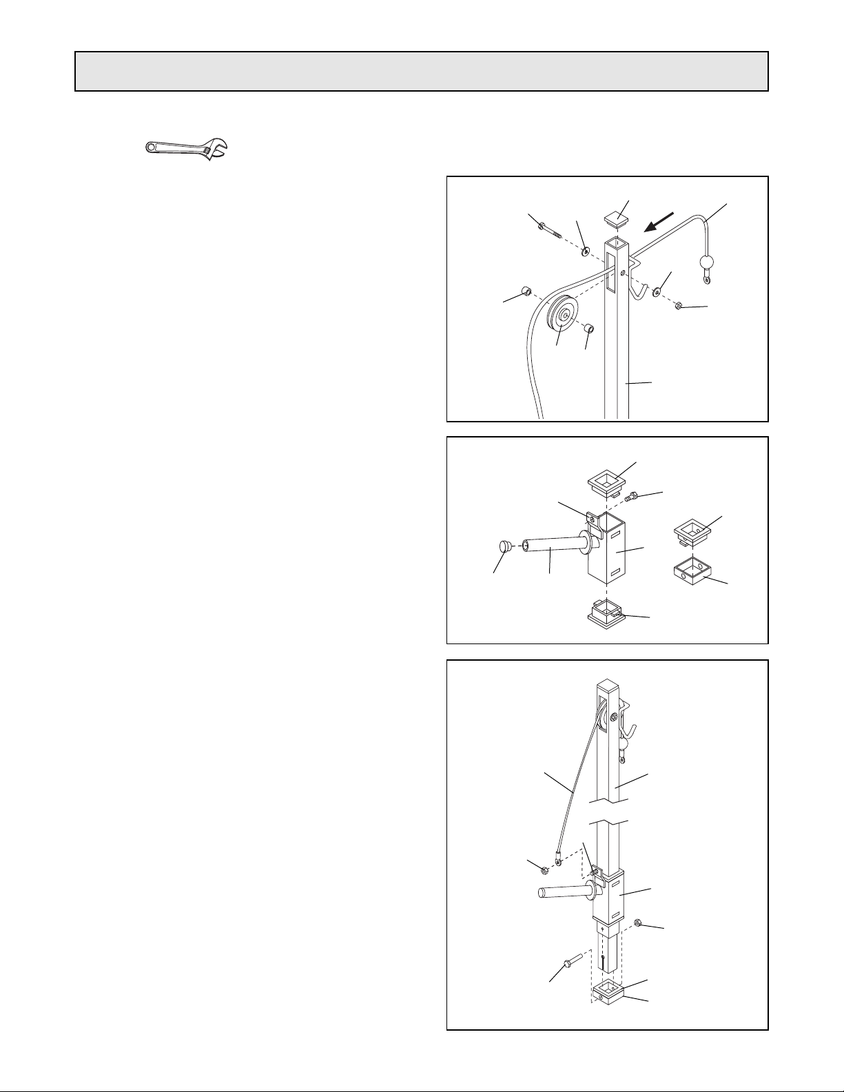
2. Press Carriage Bushings (10) onto the top and bot-
tom of the Weight Carriage (12). Press a 1Ó Round
Inner Cap (13) into the weight tube on the Weight
Carriage (12).
Insert the M8 x 16mm Bolt (11) into the bracket on
the Weight Carriage (12) from the indicated direction.
Press the last Carriage Bushing (10) into the Carriage
Stop (15) as shown.
10
11
10
15
10
12
13
Bracket
Weight
Tube
1. Locate the Cable (7) and note that it has a loop on
one end and a ball on the other end. Insert the end
with the loop through the slot in the Lat Tower (1)
from the direction shown.
Next, lay the Cable (7) in the groove of the Pulley (6).
Attach the Pulley inside the slot in the Lat Tower (1)
with the M10 x 65mm Bolt (2), two M10 Washers (3),
two Pulley Spacers (5), and an M10 Nylon Locknut
(9).
Press a 2Ó Square Inner Cap (4) into the top of the
Lat Tower (1).
1
5
3
1
9
6
3
5
4
7
2
3. Slide the Weight Carriage (12) onto the Lat Tower (1).
Make sure that the Weight Carriage is oriented as
shown.
Slide the loop on the Cable (7) onto the M8x 16mm
Bolt (11) in the Weight Carriage (12). Attach the
Cable with an M8 Nylon Locknut (14).
Next, slide the Carriage Stop (15) onto the Lat Tower
(1). Make sure that the Carriage Stop is turned so the
lip of the Carriage Bushing (10) is on top. Attach the
Carriage Stop to the indicated hole in the Lat Tower
with the M8 x 70mm Bolt (16) and an M8 Nylon
Locknut (14).
3
12
11
16
14
15
10
14
7
1
Assembly
Place all parts in a cleared area and remove the packing materials. Do not dispose of the packing materials until
assembly is completed. The following tools (not included) are required for assembly: Two (2) adjustable
wrenches .
Page 3

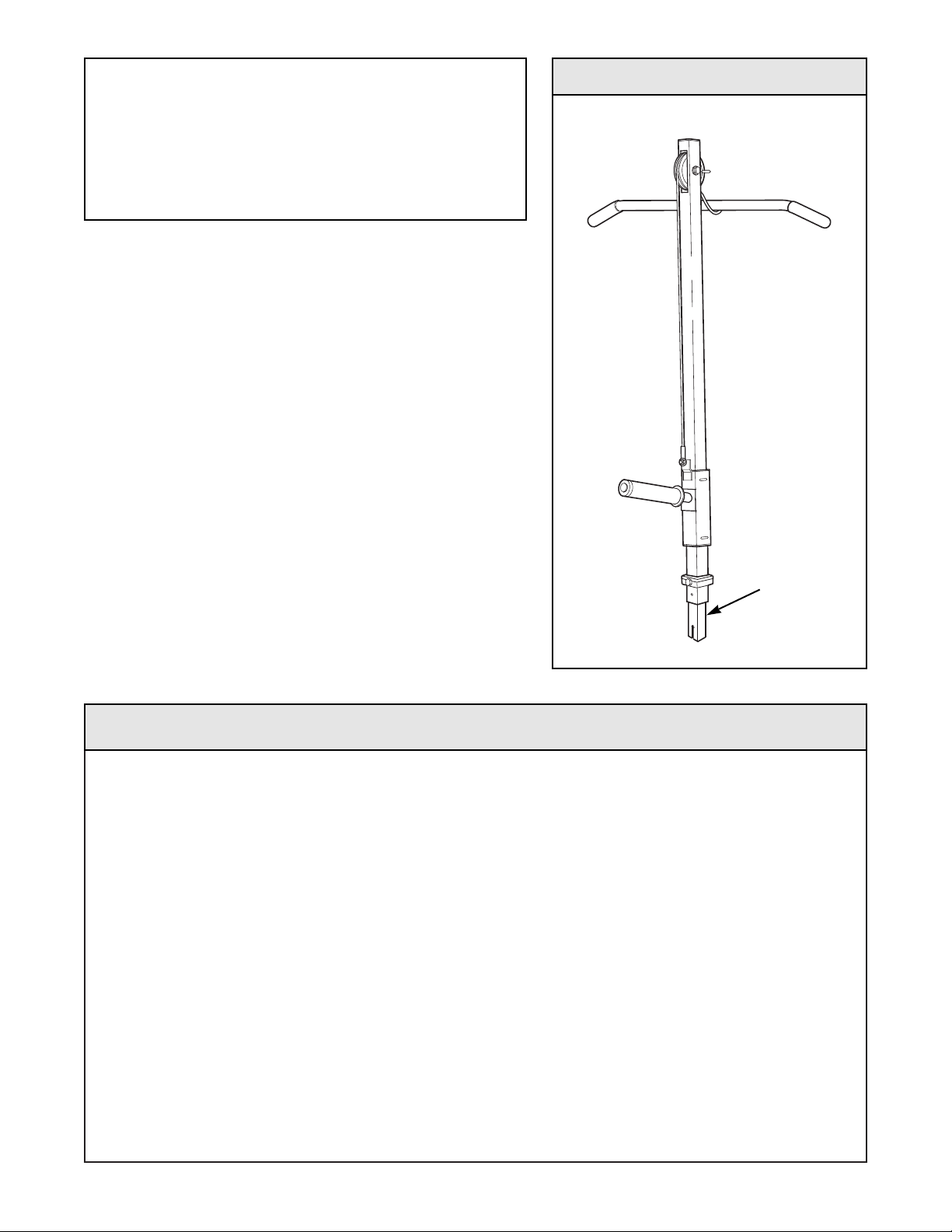
Insert the Lat Tower (1) into the front leg of the weight
bench. Make sure that the Lat Tower is turned as
shown. Secure the Lat Tower with the adjustment knob
included with the weight bench.
When the Lat Tower (1) is not in use, store it in a safe
place where it cannot cause injury by tipping over.
To use the Lat Bar (18), attach it to the end of the Cable
(7) with the Cable Clip (8).
Note: If the Grips (17) are not pre-assembled, press them
onto the ends of the Lat Bar (18).
Next, slide the desired amount of weight (not included)
onto the weight tube on the Weight Carriage (12).
If you are using olympic-size weights, slide the Adapter
(19) onto the weight tube as shown in the inset drawing.
1
How to Use the Lat Tower
18
19
12
17
17
8
7
WARNING: Do not place more than 150 pounds
on the weight carriage.
When performing an exercise with your back to
the lat tower, make sure there is enough space
between your back and the weight carriage.
Always lower the weight carriage in a controlled
manner. Never let the weight carriage drop.
Adjustment
Knob
Front Leg
Page 4
Part No. 160466 R1299A Printed in China © 1999 ICON Health & Fitness, Inc.
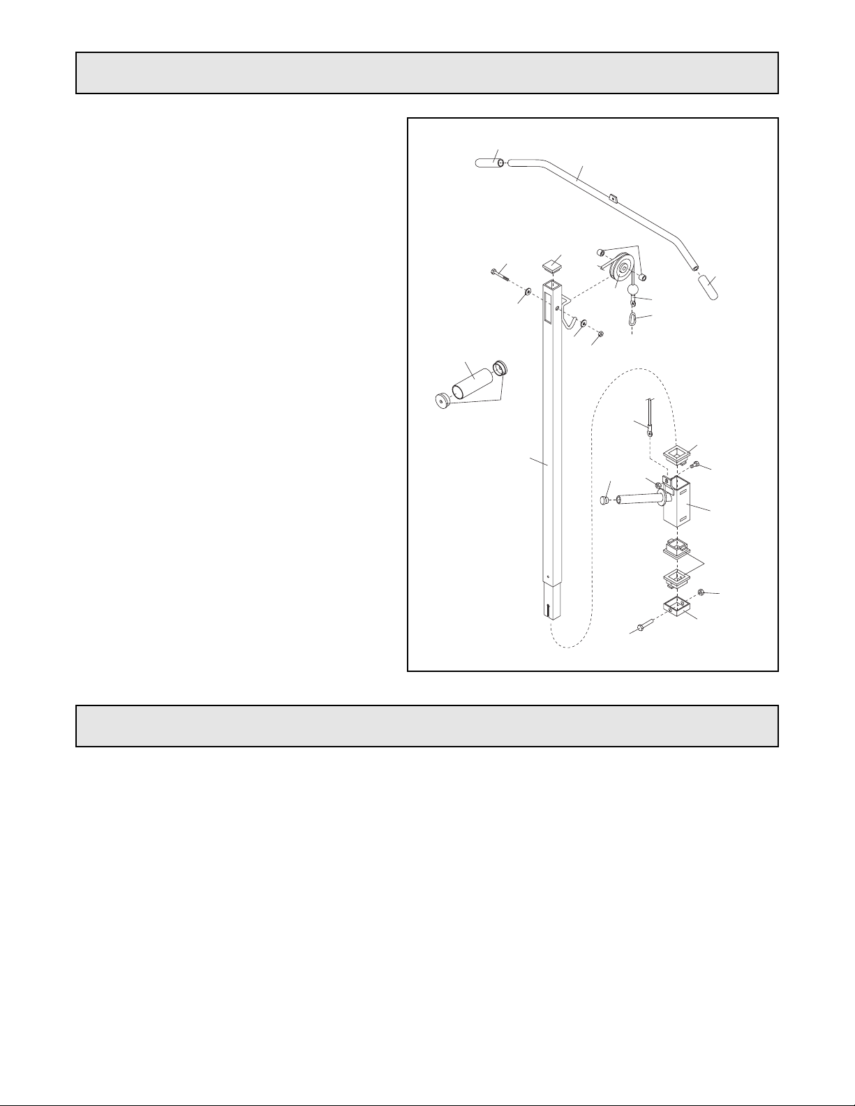
To order replacement parts, simply call our Customer Service Department toll-free at 1-800-999-3756, Monday
through Friday, 6 a.m. until 6 p.m. Mountain Time (excluding holidays). To help us assist you, please be prepared to give the following information when calling:
¥ The MODEL NUMBER of the product (PFSA20000)
¥ The NAME of the product (lat tower)
¥ The SERIAL NUMBER of the product (see the front cover of this manual)
¥ The KEY NUMBER and DESCRIPTION of the desired part(s) (see the PART LIST and the EXPLODED
DRAWING above).
5
7
6
8
2
3
3
9
4
18
17
17
19
20
14
7
11
1
10
12
10
13
14
16
15
Key No. Qty. Description
1 1 Lat Tower
2 1 M10 x 65mm Bolt
3 2 M10 Washer
4 1 2Ó Square Inner Cap
5 2 Pulley Spacer
6 1 Pulley
7 1 Cable
8 1 Cable Clip
9 1 M10 Nylon Locknut
10 3 Carriage Bushing
11 1 M8 x 16mm Bolt
12 1 Weight Carriage
13 1 1Ó Round Inner Cap
14 2 M8 Nylon Locknut
15 1 Carriage Stop
16 1 M8 x 70mm Bolt
17 2 Grip
18 1 Lat Bar
19 1 Weight Adapter
20 2 Adapter Bushing
# 1 UserÕs Manual
Note: Ò#Ó indicates a non-illustrated part.
Specifications are subject to change without
notice.
Part List/Exploded DrawingÑModel No. PFSA20000
Ordering Replacement Parts
 Loading...