

Page 1
Heart Rate Monitor User’ s Guide
Model No.
PFMC99110
Congratulations for purchasing the new AccuRate™
heart rate monitor. To install and use the heart rate
monitor, read and follow all instructions in this
user’s guide. For detailed instructions about using
the heart rate monitor with your treadmill, refer to the
user’s manual included with your treadmill.
This device complies with Part 15 of the FCC rules.
Operation is subject to the following conditions: (1)
this device may not cause harmful interference, and
(2) this device must accept any interference received, including interference that may cause undesired operation. Changes or modifications not expressly approved by ICON Health & Fitness, Inc.
could void the user’s authority to operate this device.
WARNING
If you have an implanted medical device such
as a pacemaker, check with your physician before using the heart rate monitor.
If you have heart problems, or if you are over 60
years of age and have been inactive, do not use
pulse-driven programs.
If you are taking medication regularly, consult
your physician to find whether the medication
will affect your exercise heart rate.
Page 2
2
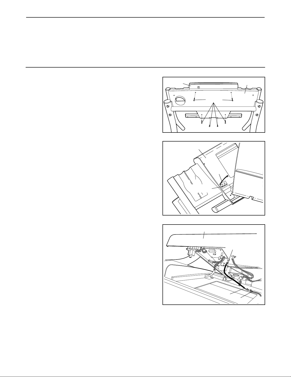
How to Install the Receiver
Before the heart rate monitor can be used, the included receiver must be installed. Pages 2 through 7 of this
user’s guide include eight sections that show how the receiver is to be installed in eight different styles of treadmills. Look at pages 2 through 7 and find the drawings that most closely resemble your treadmill. Then,
follow the instructions in that section to install the receiver. Note: Your treadmill may not look exactly like the
treadmills shown in the drawings. If you have questions, call toll-free 1-800-999-3756.
1. Make sure that the power cord is unplugged. Remove
the indicated Screws from the Console Back (A).
Important: The Screws may be different lengths. Keep
track of which Screws were removed from which holes.
2. Peel the paper off the pad on the bottom of the Receiver
(B). Turn the Receiver so the cylinder is on the side
shown, and press the Receiver into the bottom of the
Console Base (C) in the indicated location.
A
C
Screws
1
2
C
B
Cylinder
3. Connect the Short Jumper Wire (D) to the wire on the
Receiver (B). Connect the other end of the Short Jumper
Wire to the PULSE jack on the back of the Console (C). If
there is a wire already plugged into the PULSE jack, unplug it. Note: The included Long Jumper Wire can be discarded. The Wire Tie can be used to tie wires if needed.
Make sure that no wires are pinched. See step 1.
Reattach the Console (C) with the 1” Screws, 1 3/4”
Screws, and 2” Screws. Important: If the Screws are
not put back into the same holes that they were
removed from, the Console will be damaged.
3
C
B
D
PULSE
Jack
Page 3
3
1. Make sure that the power cord is unplugged. Remove
the indicated Screws (A) from the Console Back (B).
2. Peel the paper off the pad on the bottom of the Receiver
(C). Turn the Receiver so the cylinder is on the side
shown, and press the Receiver into the bottom of the
Console Back (B) in the indicated location.
Connect the Short Jumper Wire (D) to the wire on the
Receiver (C). Connect the other end of the Short Jumper
Wire to the PULSE jack on the back of the Console (E).
Note: The included Long Jumper Wire can be discarded.
The Wire Tie can be used to tie wires if needed.
Make sure that no wires are pinched. See step 1.
Reattach the Console Base (E) with the Screws (A).
B
E
A
1
2
PULSE
Jack
D
E
C
B
Cylinder
Page 4
4
2b
D
B
1. Make sure that the power cord is unplugged. Remove
the indicated Screws (A) from the Console Back (B).
Remove the Console Back from the Console Base (E).
2. Connect the Short Jumper Wire (C) to the wire on the
Receiver (D). Connect the other end of the Short Jumper
Wire to the PULSE jack on the back of the Console (see
drawing 2b). If there is a wire already plugged into the
PULSE jack, unplug it. Next, peel the paper off the pad on
the back of the Receiver (D). Turn the Receiver so the
cylinder is on the side shown, and press the Receiver
into the bottom of the Console Base (B) in the indicated location. Note: The included Long Jumper Wire can be discarded. The Wire Tie can be used to tie wires if needed.
Make sure that no wires are pinched. See step 1.
Reattach the Console Back (B) with the Screws (A).
B
E
A
1
C
2a
Cylinder
1. Make sure that the power cord is unplugged. Remove
the indicated Screws (A) from the Console Back (B).
Remove the Console Back from the Console Base (C).
2. Connect the Long Jumper Wire (D) to the wire on the
Receiver (E). Feed the Long Jumper Wire through the
holes with the other wires as shown. Connect the other
end of the Long Jumper Wire to the PULSE jack on the
back of the Console (F). If there is a wire already plugged
into the PULSE jack, unplug it. Turn the Receiver so the
cylinder is on the side shown, and press the Receiver
onto the back of the Console Base (C) in the indicated location. Note: The included Short Jumper Wire can be discarded. The Wire Tie can be used to tie wires if needed.
Make sure that no wires are pinched. See step 1.
Reattach the Console Back (B).
B
C
A
1
PULSE Jack
2
E
Cylinder
F
D
C
PULSE
Jack
Page 5

5
1. Make sure that the power cord is unplugged. Remove
the indicated Screws (A) from the Console Back (B).
Remove the Console Back from the Console Base (C).
3. Connect the Long Jumper Wire (E) to the PULSE jack on
the back of the Console (F). If there is a wire already
plugged into the PULSE jack, unplug it. Feed the Long
Jumper Wire through the hole in the side of the Console
Base (C).
4. Connect the Long Jumper Wire (E) to the wire on the
Receiver (G). Next, peel the paper off the pad on the
back of the Receiver. Turn the Receiver so the cylinder
is on the side shown, and press the Receiver onto the
back of the Console Base (C) in the indicated location.
Note: The included Short Jumper Wire can be discarded.
The Wire Tie can be used to tie wires if needed.
Make sure that no wires are pinched. See steps 2 and
1. Reattach the Console (F) and the Console Back (B).
2. Have a second person hold the Console Base (C) as you
remove the indicated Screws (D) from the Console Base.
B
C
A
1
C
2
C
3
PULSE Jack
E
F
C
Cylinder
4
E
G
D
Page 6
6
D
Note: If you have a PROFORM 785Pi or model number
PFTL79100, please call 1-800-999-3756.
1. Make sure that the power cord is unplugged. Remove
the indicated Screws (A) from the Console Back (B).
Remove the Console Back from the Console Base (E).
2. Locate the loose Pulse Wire (C) inside the Console Base
(E). Connect the Pulse Wire to the wire on the Receiver
(D). Next, peel the paper off the pad on the bottom of the
Receiver (D). Turn the Receiver so the small cylinder
is on the side shown, and press the Receiver into the
bottom of the Console Base (E) in the location indicated
by the dotted line. Note: The two included jumper wires
can be discarded. The Wire Tie can be used to tie wires if
needed.
Make sure that no wires are pinched. See step 1.
Reattach the Console Back (B) with the Screws (A).
B
E
A
1
C
2
Cylinder
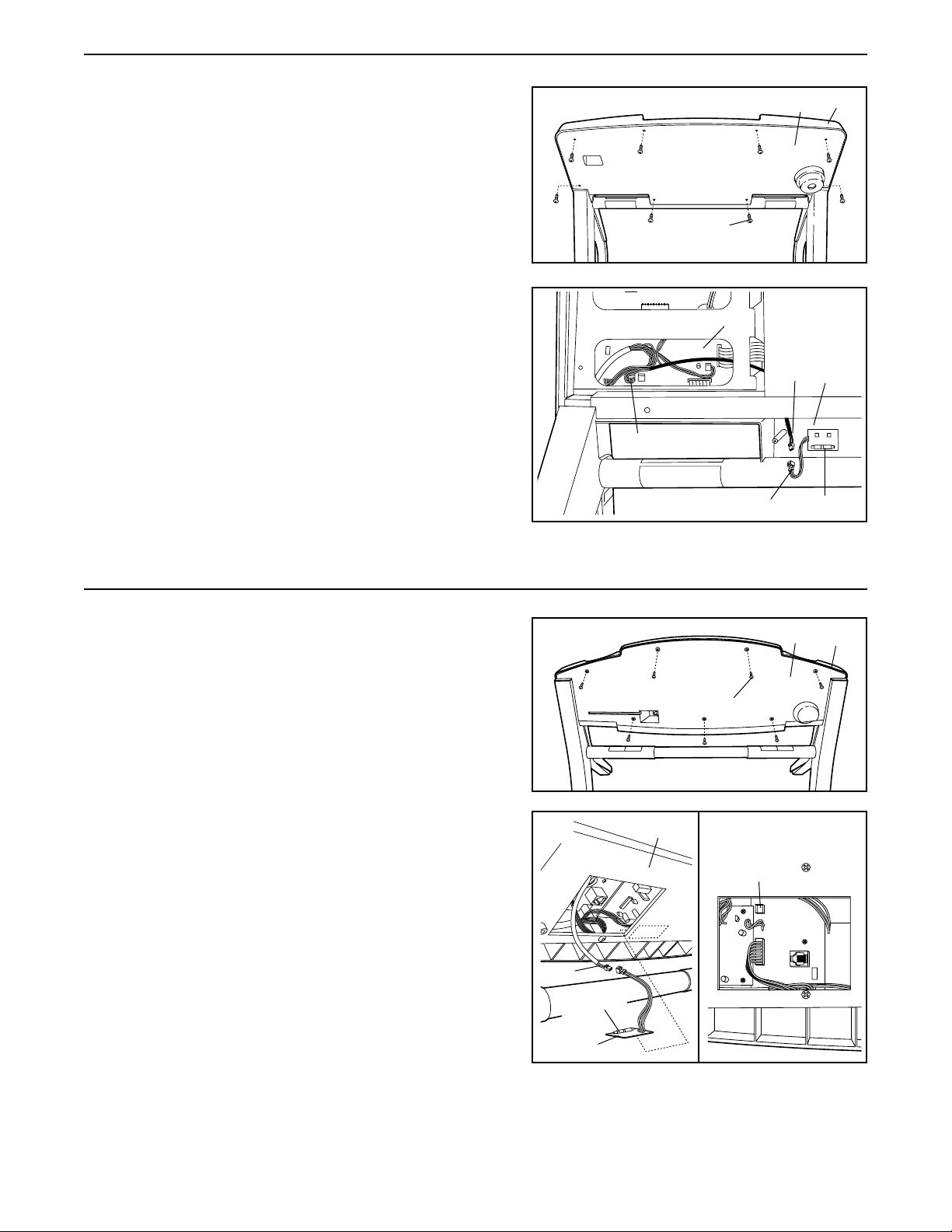
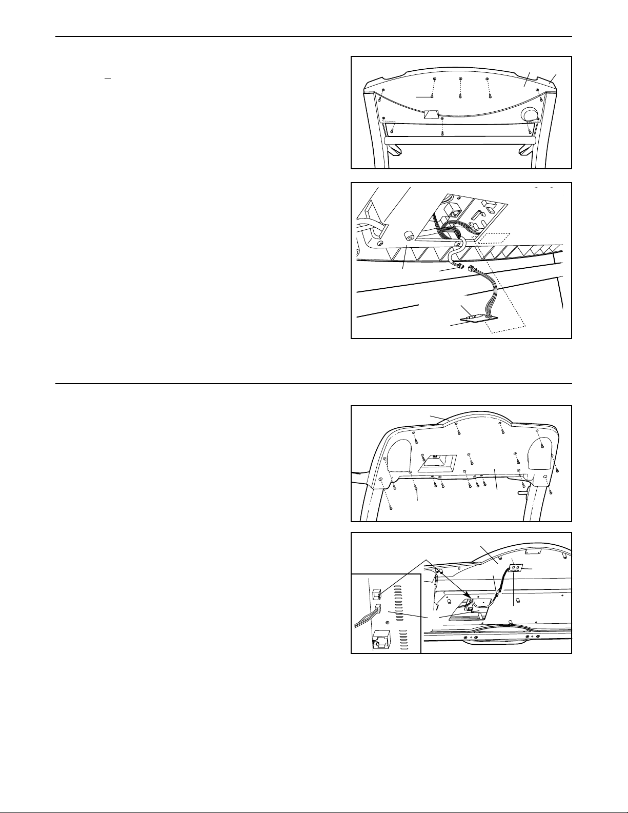
1. Make sure that the power cord is unplugged. Remove
the Screws (A) from the Console Back (B). If the Screws
are different lengths, make sure they are returned to the
same hole. Remove the Console Back from the Console
Base (C). Note: The number of Screws and the location
of the Screws may vary depending on the model of your
treadmill.
3. Connect the Long Jumper Wire (D) to the PULSE #1 jack
on the back of the Console (E) (refer to the inset drawing). Connect the other end of the Long Jumper Wire to
the wire on the Receiver (F). Next, peel the paper off the
pad on the back of the Receiver. Turn the Receiver so
the cylinder is on the side shown, and press the
Receiver onto the back of the Console Base (C) in the indicated location. Note: The included Short Jumper Wire
can be discarded. The Wire Tie can be used to tie wires if
needed.
Make sure that no wires are pinched. Refer to step 1
and reattach the Console Back (B).
B
A
1
2
PULSE Jack
E
C
C
D
F
Cylinder
E
PULSE #1
Page 7

7
PULSE 2
These instructions are to be used with the HealthRider T90
with a TV.
1. Make sure that the power cord is unplugged. Remove
the indicated Screws from the Console Back (A).
Important: The Screws may be different lengths. Keep
track of which Screws were removed from which holes.
2. Raise the Console (C) enough to view the back of the
Console. Peel the paper off the pad on the bottom of the
Receiver (B). Turn the Receiver so the cylinder is on
the side shown, and press the Receiver onto the back of
the Console in the indicated location.
3. Connect the Short Jumper Wire (D) to the wire on the
Receiver (B). Connect the other end of the Short Jumper
Wire to the PULSE 2 jack on the back of the Console (C).
If there is a wire already plugged into the PULSE 2 jack,
unplug it. Note: The included Long Jumper Wire can be
discarded. The Wire Tie can be used to tie wires if
needed.
Make sure that no wires are pinched. See step 1.
Reattach the Console (C) with the Screws. Important: If
the Screws are not put back into the same holes that
they were removed from, the Console will be damaged.
Screws
A
C
1
PULSE #2
C
B
2
Cylinder
D
C
Page 8

8
How to Use the Heart Rate Monitor
The unique heart rate monitor is specially designed for
accuracy, comfort, and durability. To get the best performance from the heart rate monitor, please read the
instructions below.
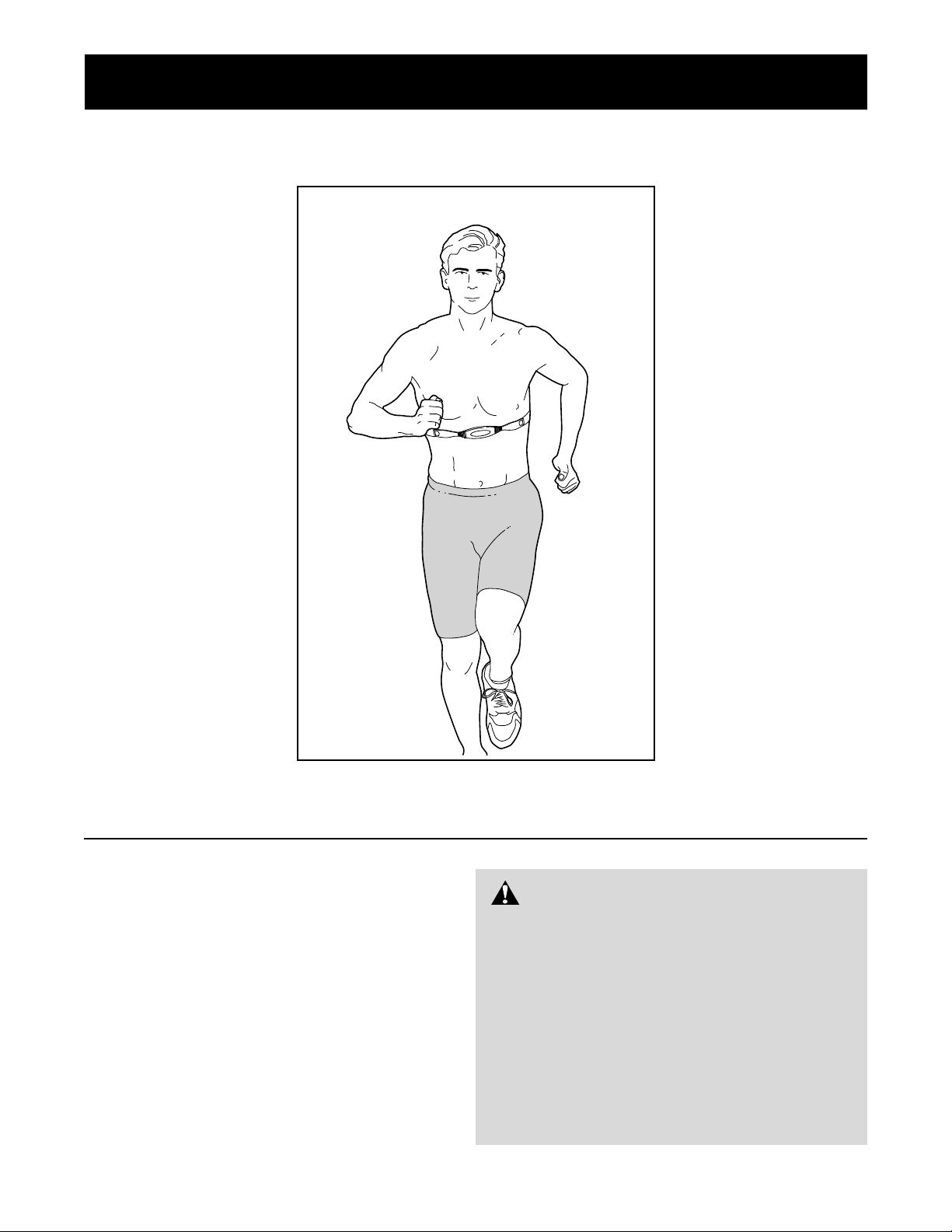
HOW TO PUT ON THE HEART RATE MONITOR
The heart rate monitor consists of two components:
the chest strap and the sensor unit. Follow the steps
below to put on the heart rate monitor.
Refer to the inset drawing above. Insert the tab
on one end of the chest strap through one end of
the sensor unit as shown. Make sure to press the
end of the sensor unit under the buckle on the
chest strap.
Wrap the
heart rate
monitor
around
your chest.
Attach the
other end
of the chest
strap to the sensor unit as described above.
Adjust the length of the chest strap, if necessary.
The heart rate monitor should be under your
clothing, against your skin, and as high under the
pectoral muscles or breasts as is comfortable.
Make sure that the logo is facing forward and is
right-side-up.
Pull the
sensor unit
away from
your body
a few
inches and
locate the
two electrode areas on the inner side. Using a saline solu-
tion such as saliva or contact lens solution, wet
both electrode areas. Return the sensor unit to a
position against your chest.
HEART RATE MONITOR TROUBLESHOOTING
If the heart rate monitor does not function properly,
or if the displayed heart rate is excessively high or
low, try the troubleshooting steps below.
• Make sure that the heart rate monitor is under your
clothing, against your skin, and as high under the
pectoral muscles or breasts as is comfortable. Note:
If the heart rate monitor does not function when positioned as described, try moving it slightly lower or
higher on your chest.
• Make sure that the logo on the sensor unit is facing
forward and is right-side-up.
• Each time you use the heart rate monitor, use saline
solution such as saliva or contact lens solution to wet
the two electrode areas on the sensor unit (see the
drawing below). If heart rate readings do not appear
until you begin perspiring, re-wet the electrode areas.
• As you walk or run on the treadmill, make sure that
you are near the center of the walking belt and within
arm’s length of the console. For the console to dis-
play heart rate readings, the user must be within
arm’s length of the console.
• The heart rate monitor is designed to work with people who have normal heart rhythms. Heart rate reading problems may be caused by medical conditions
such as premature ventricular contractions (pvcs),
tachycardia bursts, and arrhythmia.
• The operation of the heart rate monitor can be affected by magnetic interference caused by high
power lines or other sources. If it is suspected that
magnetic interference may be causing a problem,
try relocating the treadmill.
• If the heart rate monitor still does not function properly, test the heart rate monitor in the following way:
Hold the heart
rate monitor
and place your
thumbs over
the electrode
areas as
shown.
3
2
1
Chest Strap
Sensor Unit
Tab
Buckle
Logo
Electrode Areas
Sensor
Unit
Electrode Areas
Page 9
9
Next, hold the heart rate monitor near the console.
While holding one thumb stationary, begin tapping
the other thumb against the electrode area at a rate
of about one tap per second. Check the heart rate
reading on the console.
• If the heart rate monitor does not function properly
after you have followed all of the above instructions,
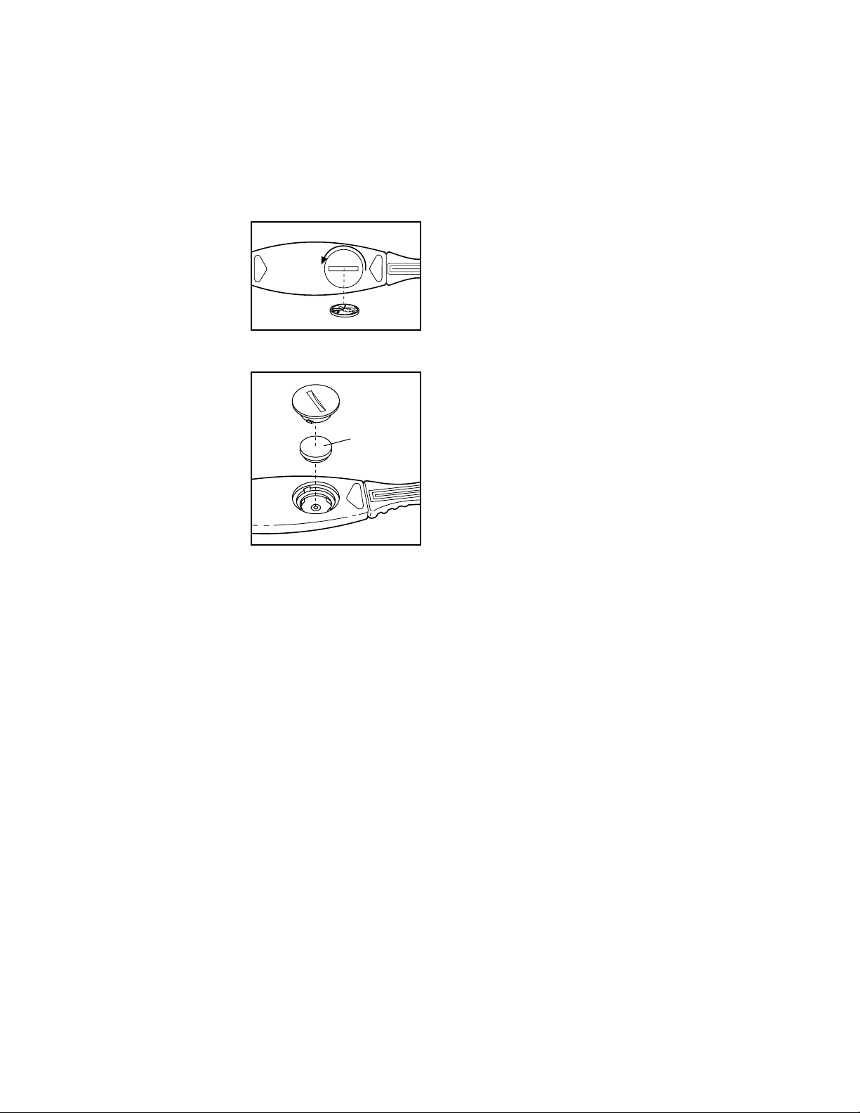
the battery should be replaced in the following way:
Locate the battery
cover on the back of
the sensor unit. Insert
a coin into the slot in
the cover, turn the
cover counterclockwise, and remove the
cover.
Remove the old battery and insert a new
CR 2032 battery.
Make sure that the
battery is turned so
the writing is on
top. Replace the
battery cover and
turn it clockwise to
close it.
HEART RATE MONITOR CARE
• Thoroughly dry the heart rate monitor after each
use. The heart rate monitor is activated when the
electrode areas are wetted and the heart rate monitor is put on; the heart rate monitor shuts off when it
is removed and the electrode areas are dried. If the
heart rate monitor is not dried after each use, it may
remain activated longer than necessary, draining the
battery prematurely.
• Store the heart rate monitor in a warm, dry place.
Do not store the heart rate monitor in a plastic bag
or other container that may trap moisture.
• Do not expose the heart rate monitor to direct
sunlight for extended periods of time. Do not expose
the heart rate monitor to temperatures above 122°
Fahrenheit (50° Celsius) or below 14° Fahrenheit
(-10° Celsius).
• Do not excessively bend or stretch the sensor unit
when using or storing the heart rate monitor.
• Clean the sensor unit using a damp cloth—never
use alcohol, abrasives, or chemicals. The chest
strap may be hand washed and air dried.
CR 2032
Battery
Page 10
10
The following guidelines will help you to plan your exercise program. For more detailed exercise information, obtain a reputable book or consult your physician.
EXERCISE INTENSITY
Whether your goal is to burn fat or to strengthen your
cardiovascular system, the key to achieving the
desired results is to exercise with the proper intensity.
The proper intensity level can be found by using your
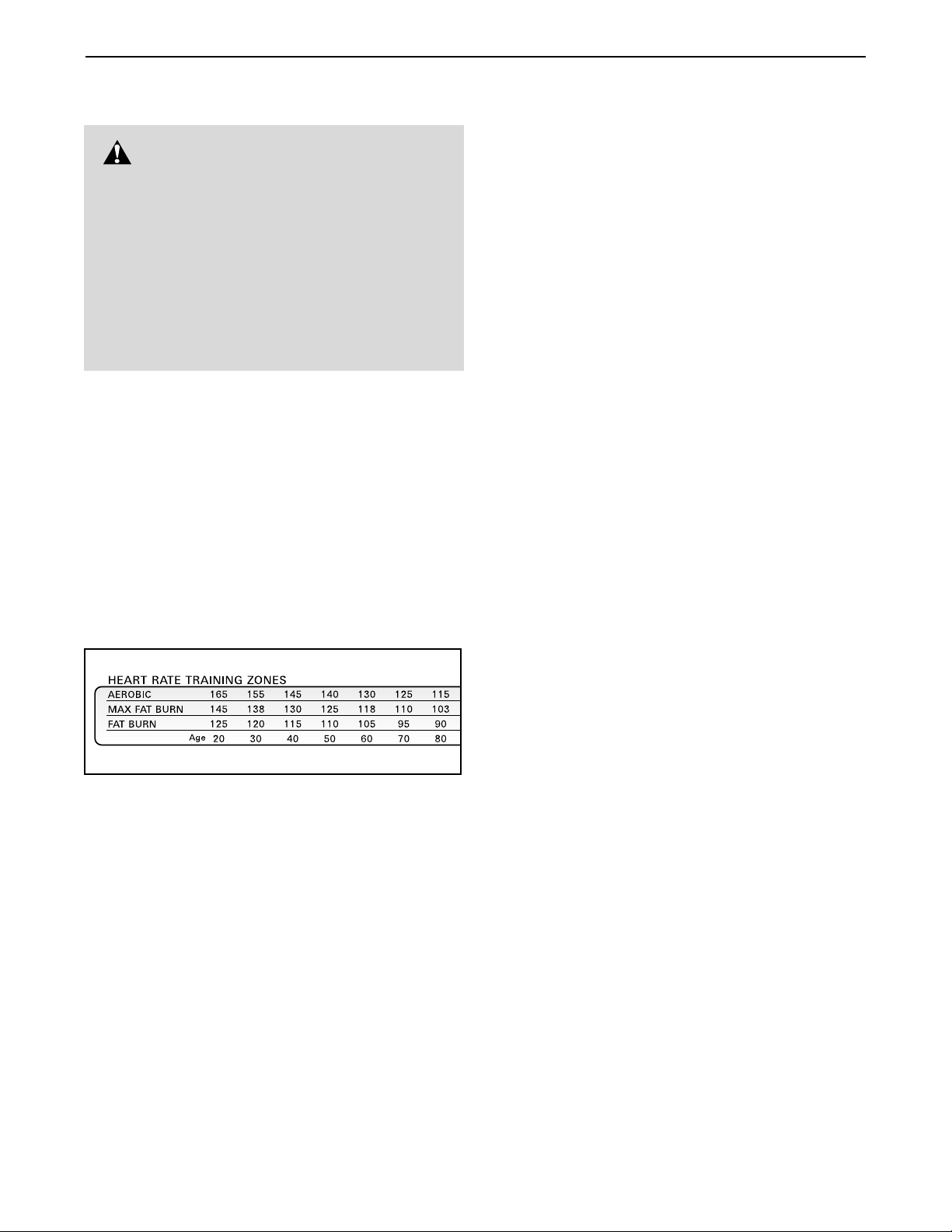
heart rate as a guide. The chart below shows recommended heart rates for fat burning and aerobic exercise.
To find the proper heart rate for you, first find your age
near the bottom of the chart (ages are rounded off to
the nearest ten years). Next, find the three numbers
above your age. The three numbers define your “training zone.” The lower two numbers are recommended
heart rates for fat burning; the highest number is the
recommended heart rate for aerobic exercise.
To measure your heart rate during exercise, use the
chest pulse sensor. If your heart rate is too high or too
low, adjust the speed or incline of the treadmill.
Fat Burning
To burn fat effectively, you must exercise at a relatively
low intensity level for a sustained period of time.
During the first few minutes of exercise, your body
uses easily accessible carbohydrate calories for en-
ergy. Only after the first few minutes does your body
begin to use stored fat calories for energy. If your goal
is to burn fat, adjust the speed or incline of the treadmill until your heart rate is near the lowest number in
your training zone.
For maximum fat burning, adjust the speed or incline
of the treadmill until your heart rate is near the middle
number in your training zone.
Aerobic Exercise
If your goal is to strengthen your cardiovascular system, your exercise must be “aerobic.” Aerobic exercise
is activity that requires large amounts of oxygen for
prolonged periods of time. This increases the demand
on the heart to pump blood to the muscles, and on the
lungs to oxygenate the blood. For aerobic exercise,
adjust the speed or incline of the treadmill until your
heart rate is near the highest number in your training
zone.
WORKOUT GUIDELINES
Each workout should include the following three parts:
A Warm-up—Start each workout with 5 to 10 minutes
of stretching and light exercise. A proper warm-up increases your body temperature, heart rate and circulation in preparation for exercise.
Training Zone Exercise—After warming up, increase
the intensity of your exercise until your pulse is in your
training zone for 20 to 60 minutes. (During the first few
weeks of your exercise program, do not keep your
pulse in your training zone for longer than 20 minutes.)
Breathe regularly and deeply as you exercise—never
hold your breath.
A Cool-down—Finish each workout with 5 to 10 minutes of stretching to cool down. This will increase the
flexibility of your muscles and will help prevent post-exercise problems.
EXERCISE FREQUENCY
To maintain or improve your condition, complete three
workouts each week, with at least one day of rest between workouts. After a few months, you may complete up to five workouts each week if desired.
The key to success is to make exercise a regular and
enjoyable part of your everyday life.
Conditioning Guidelines
WARNING:Before beginning this
or any exercise program, consult your physician. This is especially important for individuals over the age of 35 or individuals with preexisting health problems.
The pulse sensor is not a medical device.
Various factors, including your movement,
may affect the accuracy of heart rate readings.
The sensor is intended only as an exercise aid
in determining heart rate trends in general.
Page 11

11
SUGGESTED STRETCHES
The correct form for several basic stretches is shown at the right. Move slowly as you stretch—never bounce.
1. Toe Touch Stretch
Stand with your knees bent slightly and slowly bend forward from
your hips. Allow your back and shoulders to relax as you reach
down toward your toes as far as possible. Hold for 15 counts,
then relax. Repeat 3 times. Stretches: Hamstrings, back of knees
and back.
2. Hamstring Stretch
Sit with one leg extended. Bring the sole of the opposite foot toward you and rest it against the inner thigh of your extended leg.
Reach toward your toes as far as possible. Hold for 15 counts,
then relax. Repeat 3 times for each leg. Stretches: Hamstrings,
lower back and groin.
3. Calf/Achilles Stretch
With one leg in front of the other, reach forward and place your
hands against a wall. Keep your back leg straight and your back
foot flat on the floor. Bend your front leg, lean forward and move
your hips toward the wall. Hold for 15 counts, then relax. Repeat
3 times for each leg. To cause further stretching of the achilles
tendons, bend your back leg as well. Stretches: Calves, achilles
tendons and ankles.
4. Quadriceps Stretch
With one hand against a wall for balance, reach back and grasp
one foot with your other hand. Bring your heel as close to your
buttocks as possible. Hold for 15 counts, then relax. Repeat 3
times for each leg. Stretches: Quadriceps and hip muscles.
5. Inner Thigh Stretch
Sit with the soles of your feet together and your knees outward.
Pull your feet toward your groin area as far as possible. Hold for
15 counts, then relax. Repeat 3 times. Stretches: Quadriceps
and hip muscles.
1
2
3
4
5
Page 12

Part No. 177861 R0502A Printed in USA © 2002 ICON Health & Fitness, Inc.
Limited Warranty
WHAT IS COVERED—The HEART RATE MONITOR (“product”) is warranted to be free of all defects
in material and workmanship.
WHO IS COVERED—The original purchaser or any
person receiving the product as a gift from the original purchaser.
HOW LONG IS IT COVERED—ICON Health &
Fitness, Inc. (“ICON”), warrants the product for one
year after the date of purchase.
WHAT WE DO TO CORRECT COVERED DEFECTS—We will ship to you, without charge, any replacement part or component, or, at our option, we
will replace the product.
WHAT IS NOT COVERED—Any failures or damage
caused by unauthorized service, misuse, accident,
negligence, improper assembly or installation, alterations, modifications without our written authorization
or by failure on your part to use, operate, and maintain as set out in this manual (“manual”). This warranty does not extend to products used for commercial or rental purposes or to products used as store
display models.
WHAT YOU MUST DO—Always retain proof of purchase, such as your bill of sale; store, operate, and
maintain the product as specified in the manual; notify our Customer Service Department of any defect
within 10 days after discovery of the defect; as instructed, return any defected part for replacement or,
if necessary, the entire product, for repair.
MANUAL—It is VERY IMPORTANT THAT YOU
READ THIS MANUAL before using the product.
Remember to follow the instructions specified in this
manual to assure proper operation and your continued satisfaction.
HOW TO GET PARTS AND SERVICE—Simply call
our Customer Service Department at 1-800-9993756 and tell them your name and address and the
model number of your product. They will tell you how
to get a part replaced, or advise you how to ship the
product for service. Before shipping, always obtain a
Return Authorization Number (RA No.) from our
Customer Service Department; securely pack your
product (save the original shipping carton if possible);
put the RA No. on the outside of the carton and insure the product. Include a letter explaining the problem and a copy of your proof of purchase if you believe the service is covered by warranty.
ICON is not responsible or liable for indirect, special
or consequential damages arising out of or in connection with the use or performance of the product or
damages with respect to any economic loss, loss of
property, loss of revenues or profits, loss of enjoyment or use, costs of removal, installation or other
consequential damages of whatsoever nature. Some
states do not allow the exclusion or limitation of incidental or consequential damages. Accordingly, the
above limitation may not apply to you.
The warranty extended hereunder is in lieu of any and
all other warranties and any implied warranties of
merchantability or fitness for a particular purpose is
limited in its scope and duration to the terms set forth
herein. Some states do not allow limitations on how
long an implied warranty lasts. Accordingly, the above
limitation may not apply to you. No one is authorized
to change, modify or extend the terms of this limited
warranty. This warranty gives you specific legal rights
and you may have other rights which vary from state
to state.
ICON Health & Fitness, Inc.
1500 S. 1000 W., Logan, UT 84321
 Loading...