

Page 1

USERʼS MANUAL
Visit our website
www.iconsupport.eu
Model No. : PFIVEL63012.0
Serial No ___________
CAUTION
Read all precautions and instructions in this manual before using
this equipment. Keep this manual
for future reference.
QUESTIONS ?
If you have questions, or if there are
missing parts, please contact us:
UK
Call: 08457 089 009
From Ireland: 053 92 36102
Website: www.iconsupport.eu
E-mail: csuk@iconeurope.com
Write:
ICON Health & Fitness, Ltd.
c/o HI Group PLC
Express Way
Whitwood, West Yorkshire
WF10 5QJ
UK
Write the serial number in the
space above for reference.
Serial number decal
Page 2

2
TABLE OF CONTENTS
IMPORTANT PRECAUTIONS
. . .
. . . . . . . . . . . . . . . . . . . . . . . . . . . . . . . . . . . . . . . . . . . . . . . . . . . . . . . . . . . . . . 3
BEFORE YOU BEGIN . . . . . . . . . . . . . . . . . . . . . . . . . . . . . . . . . . . . . . . . . . . . . . . . . . . . . . . . . . . . . . . . . . . . . . 4
WARNING DECAL PLACEMENT . . . . . . . . . . . . . . . . . . . . . . . . . . . . . . . . . . . . . 4
ASSEMBLY. . . . . . . . . . . . . . . . . . . . . . . . . . . . . . . . . . . . . . . . . . . . . . . . . . . . . . . . . . . . . . . . . . . . . . . . . . . . . . . . . .5
HOW TO OPERATE THE ELLIPTICAL. . . . . . . . . . . . . . . . . . .
. . . . . . . . . . .
. . . . . . . . . . . . . . . . . . . . . . . . . . . . . . . . . . . . 9
FEATURES OF THE CONSOLE . . . . . . . .
. . . . . . . . . . .
. . . . . . . . . . . . . . . . . . . . . . . . . . . . . . . . . . . . 10
MAINTENANCE AND TROUBLESHOOTING. . . . . . . . . . . . . . .
. . . . . . . . . . .
. . . . . . . . . . . . . . . . . . . . . . . . . . . . . . . . . . . . 11
EXERCISE GUIDELINES. . . . . . . . . . . . . . . . .
. . . . . . . . . . .
. . . . . . . . . . . . . . . . . . . . . . . . . . . . . . . . . . . . 12
NOTES. . . . . . . . . . . . . . . . . . . . . . . . .
. . . . . . . . . .
. . . . . . . . . . . . . . . . . . . . . . . . . . . . . . . . . . . . . . . 13
EXPLODED DRAWINGS. . . . . . . . . . . . . . . . . . . . . . . . .
. . . . . . . . . .
. . . . . . . . . . . . . . . . . . . . . . . . . . . . . . . . . . . . . . . 14
PART LIST . . . . . . . . . . . . . . . . . . . . . . . . . .
. . . . . . . . . .
. . . . . . . . . . . . . . . . . . . . . . . . . . . . . . . . . . . . . . . 15
ORDERING REPLACEMENT PARTS. . . . . . . . . . . . . . . . . . . . . . . . . . . . . . . . . . . . . . Last Page
Page 3

3
IMPORTANT PRECAUTIONS
WARNING : To reduce the risk of serious injury, read all important precautions and
instructions in this manual and all warnings on your elliptical before using your elliptical. ICON
assumes no responsibility for personal injury or property damage sustained by or through the
use of this product.
1. Before beginning any exercise program, consult your physician. This is especially important
for persons over age 35 or persons with preexisting health problems.
2. Use the elliptical only as described in this
manual.
3. It is the responsibility of the owner to ensure
that all users of the elliptical are adequately
informed of all precautions.
4. The elliptical is intended for home use only.
Do not use the elliptical in a commercial, rental,
or institutional setting.
5. Keep the elliptical indoors, away from moisture and dust. Place the elliptical on a level surface, with a mat beneath it to protect the oor
or carpet. Make sure that there is at least 3 ft.
(0.9 m) of clearance in the front and rear of the
elliptical and 2 ft. (0.6 m) on each side.
6. Inspect and properly tighten all parts regularly. Replace any worn parts immediately.
7. Keep children under age 12 and pets away
from the elliptical at all times.
8.The elliptical should not be used by persons
weighing more than 250 lbs. (115 kg).
9. Wear appropriate clothes while exercising;
do not wear loose clothes that could become
caught on the elliptical. Always wear athletic
shoes for foot protection while exercising.
10. Hold the handlebars or the upper body arms
when mounting, dismounting, or using the elliptical.
11. The pulse sensor is not a medical device.
Various factors may affect the accuracy of heart
rate readings. The pulse sensor is intended
only as an exercise aid in determining heart
rate trends in general.
12. The elliptical does not have a freewheel; the
pedals will continue to move until the ywheel
stops. Reduce your pedaling speed in a controlled way.
13. Keep your back straight while using the elliptical; do not arch your back.
14. Over exercising may result in serious injury
or death. If you feel faint or if you experience
pain while exercising, stop immediately and
cool down.
Page 4

4
BEFORE YOU BEGIN
Thank you for purchasing the ProForm® Elipse
4.0. The elliptical provides an array of features
designed to make your workouts at home more
effective and enjoyable.
For your benet, read this manual carefully before you use the elliptical. If you have questions
after reading this manual, please see the front
cover of this manual. To help us assist you, note
the product model
number and serial number before contacting us.
The model number is PFIVEL63012.0 and the location of the serial number decal are shown on the
front cover of this manual.
Before reading further, please familiarize yourself
with the parts that are labeled in the drawing below.
115 Kg
115 Kg
115 Kg
ENGLISH
115 Kg
WARNING DECAL PLACEMENT
This drawing shows the location(s) of
the warning decal(s). If a decal is missing or illegible, call the telephone number on the front cover of this manual
and request a free replacement decal.
Apply the decal in the location shown.
Note: The decal(s) may not be shown
at actual size.
Page 5

5
ASSEMBLY
Assembly requires two persons. Place all parts of the exercise cycle in a cleared area and remove
the packing materials. Do not dispose of the packing materials until assembly is completed.
In addition to the included tool(s), assembly requires an adjustable wrench and a Phillips
screwdriver .
Use the part drawings below to identify the small parts used in assembly. The number in parentheses below each drawing refers to the key number of the part, from the PART LIST near the end of
this manual. The number following the parentheses is the quantity needed for assembly. Note: Some
small parts may have been preassembled. If a part is not in the hardware kit, check to see if it has
been preassembled.
Page 6

6
STEP 1
Fix the Front bottom tube (7) and the Rear bottom
tube (8) onto the Main frame (1) with the Allen pan
head screw (11), Curved washer (12) and acorn
nut(13) as shown.
STEP 2
While another person holds the Upright (2) near
the Frame (1), connect the Extension Wire (30) to
the sensor Wire (31).
Next, connect the Resistance Cable (17) to the
Lower Cable (32) in the following way:
• See drawing A. Pull upward on the metal bracket
on the Lower Cable (32), and insert the tip of the
Resistance Cable (17) into the wire clip inside the
metal bracket as shown.
• See drawing B. Firmly pull the Resistance Cable
(17) upward and slide it into the top of the metal
bracket as shown.
• See drawing C. Using pliers, squeeze the prongs
on the upper end of the metal bracket together.
Push the Wires (30, 31) and the Cables (17, 32)
downward into the Frame (1).
Tip: Do not pinch the wires and cables. Insert the
Upright (4) into the Frame (1). Attach the Upright
with four Screws (15) and four Curved washer (12).
A
B
C
9
6
6
9
32
11
16
Metallic
support
Metallic
support
17
Page 7

7
STEP 3
Attach the Swing tube (4L/R) to the Axle of Handlebar post (2) with Hex bolt (21) and Flat washer (20).
But don’t tighten them rstly.
STEP 4
Attach the Pedal tube (3L/R) to the Cross bar (78) with Flat washer (27)and Nylon nut(28), then tighten the
Hex bolt (21) and Nylon nut (28). Finally cover the End cap (29)&(35) respectively.
Page 8

8
STEP 5
Fix the Fixed handlebar (6) to the Handlebar post (2)
with the Bolts (14), Arc washers (12) and Acorn nuts
(13).
STEP 6
Fix Handlebar (5L/R) to the Swing tubes (4L/R) with
Bolts (16), Arc washers (12) and Acorn nuts (13).
Connect the Extension wire (30) well with the wire of
Computer(
10).Then x the computer(10) on the handlebar post (2)
with Screws (33) . Finally insert the Pulse sensor wire
(36) into the hole bottom of computer (10).
Page 9

9
HOW TO EXERCISE ON THE ELLIPTICAL
EXERCISER
To mount the elliptical exerciser, hold the upper body
arms and step onto the pedal that is in the lowest
position. Then, step onto the other pedal. Push the
pedals until they begin to move with a continuous
motion.
Note: The pedal discs can turn in either direction. It is
recommended that you move the pedal discs in the
direction shown by the arrow;
however, for variety, you may turn the pedal discs
in the opposite direction.
The upper body arms are designed to add upperbody exercise to your workouts. As you exercise,
push and pull the upper body arms to work your
arms, shoulders, and back. To focus on lower-body
exercise, hold the upper body arms but do not push
or pull them as you exercise.
To dismount the elliptical exerciser, wait until the
pedals come to a complete stop. Note: The elliptical
exerciser does not have a free wheel; the pedals
will continue to move until the ywheel stops.
When the pedals are stationary, step off the highest
pedal rst. Then, step off the lower pedal.
MEASURE YOUR HEART RATE IF DESIRED
You can measure you heart rate using either the
handgrip pulse sensor or the optional chest pulse
sensor.
Note: If you hold the handgrip pulse sensor and
wear the chest pulse sensor at the same time, the
console will not display your heart rate accurately.
If there are sheets of clear plastic on the metal
contacts on the handgrip pulse sensor, remove
the plastic. In addition, make sure that your hands
are clean. To measure your heart rate, hold the
handgrip pulse sensor with your palms resting
against the metal contacts. Avoid moving your
hands or gripping the contacts tightly.
When you are nished exercising
If the pedals do not move for several minutes and
the buttons are not pressed, the console will turn
off and the display will be reset.
HOW TO USE THE ELLIPTICAL
Contacts
Page 10

10
IInspect and tighten all parts of the exercise cycle
regularly.
Replace any worn parts immediately.
To clean the exercise cycle, use a damp cloth and a
small amount of mild detergent.
Important: To avoid damaging the console, keep
liquids away from the console and keep the console
out of direct sunlight.
BATTERY REPLACEMENT
If the console display becomes dim, the batteries
should be replaced; most console problems are the
result of low batteries.
The console requires two 1,5V AA batteries; alkaline
batteries are recommended. Remove the battery
cover from the console. Insert two batteries into the
console.
Make sure that the batteries are oriented as shown
by the diagram inside the console. Then, reattach
the battery cover.
MAINTENANCE AND TROUBLESHOOTING
Page 11
11
EXERCISE GUIDELINES
WARNING:
Before beginning this or any exercise program, consult your physician. This is especially important for persons over the age of 35
or persons with pre-existing health problems.
The pulse sensor is not a medical device. Various factors may affect the accuracy of heart
rate readings. The pulse sensor is intended
only as an exercise aid in determining heart
rate trends in general.
These guidelines will help you to plan your exercise
program. For detailed exercise information, obtain a
reputable book or consult your physician. Remember,
proper nutrition and adequate rest are essential for
successful results.
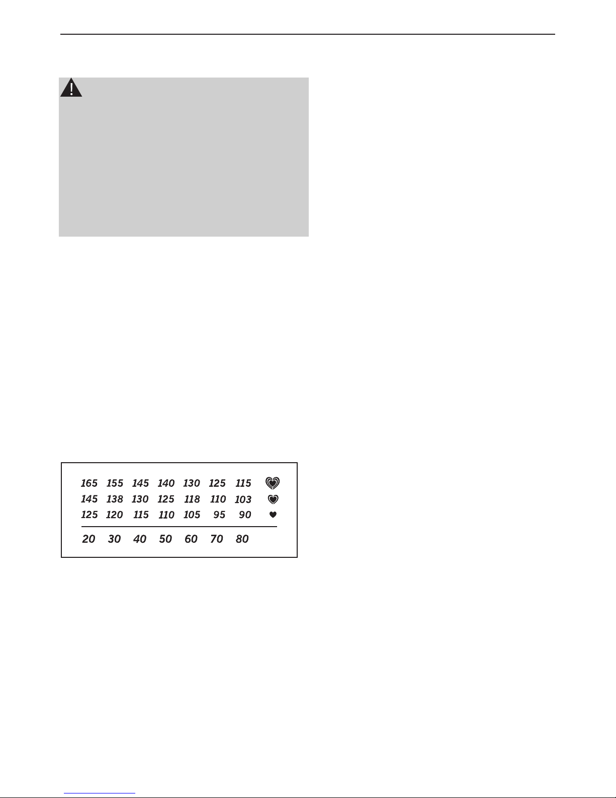
EXERCISE INTENSITY
Whether your goal is to burn fat or to strengthen your
cardiovascular system, exercising at the proper intensity is the key to achieving results. You can use
your heart rate as a guide to nd the proper intensity
level. The chart below shows recommended heart
rates for fat burning and aerobic exercise.
To nd the proper intensity level, nd your age at the
bottom of the chart (ages are rounded off to the nearest ten years). The three numbers listed above your
age dene your “training zone.” The lowest number is
the heart rate for fat burning, the middle number is
the heart rate for maximum fat burning, and the highest number is the heart rate for aerobic exercise.
Burning Fat—To burn fat effectively, you must exercise at a low intensity level for a sustained period of
time. During the rst few minutes of exercise, your
body uses carbohydrate calories for energy. Only af-
ter the rst few minutes of exercise does your body
begin to use stored fat calories for energy. If your
goal is to burn fat, adjust the intensity of your exercise until your heart rate is near the lowest number in
your training one. For maximum fat burning, exercise
with your heart rate near the middle number in your
training zone.
Aerobic Exercise—If your goal is to strengthen your
cardiovascular system, you must perform aerobic
exercise, which is activity that requires large amounts
of oxygen for prolonged periods of time. For aerobic
exercise, adjust the intensity of your exercise until
your heart rate is near the highest number in your
training zone.
WORKOUT GUIDELINES
Warming Up—Start with 5 to 10 minutes of stretching
and light exercise. A warm-up increases your body
temperature, heart rate, and circulation in preparation for exercise.
Training Zone Exercise—Exercise for 20 to 30 minutes with your heart rate in your training zone. (During
he rst few weeks of your exercise program, do not
keep your heart rate in your training zone for longer
than 20 minutes.) Breathe regularly and deeply as
you exercise–never hold your breath.
Cooling Down—Finish with 5 to 10 minutes of
stretching. Stretching increases the exibility of your
muscles and helps to prevent post-exercise problems.
EXERCISE FREQUENCY
To maintain or improve your condition, complete three
workouts each week, with at least one day of rest
between workouts. After a few months of regular ex-
ercise, you may complete up to ve workouts each
week, if desired. Remember, the key to success is to
make exercise a regular and enjoyable part of your
everyday life.
Page 12
12
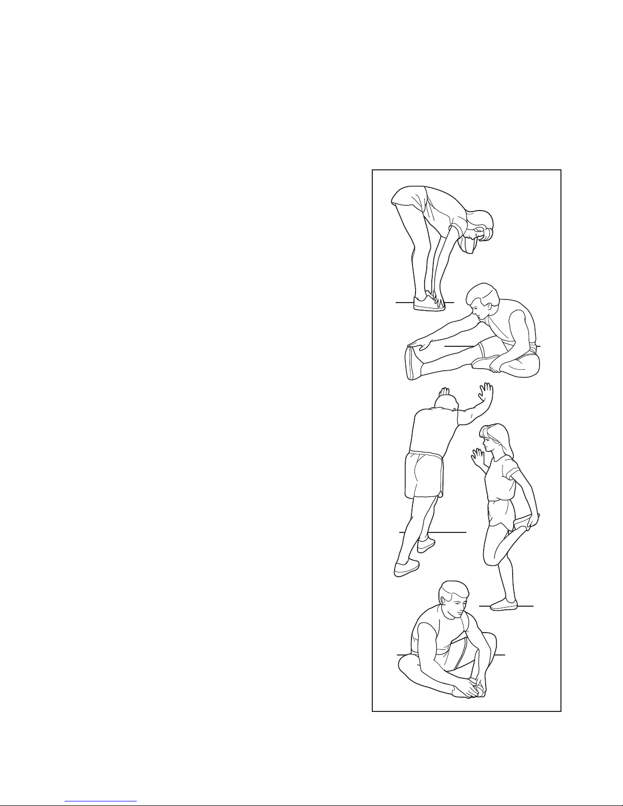
SUGGESTED STRETCHES
The correct form for several basic stretches is shown at the right.
Move slowly as you stretch—never bounce.
1. Toe Touch Stretch
Stand with your knees bent slightly and slowly bend forward from
your hips. Allow your back and shoulders to relax as you reach
down toward your toes as far as possible. Hold for 15 counts,
then relax. Repeat 3 times. Stretches: Hamstrings, back of
knees, and back.
2. Hamstring Stretch
Sit with one leg extended. Bring the sole of the opposite foot
toward you and rest it against the inner thigh of your extended
leg. Reach toward your toes as far as possible. Hold for 15
counts, then relax. Repeat 3 times for each leg. Stretches:
Hamstrings, lower back, and groin.
3. Calf/Achilles Stretch
With one leg in front of the other, reach forward and place your
hands against a wall. Keep your back leg straight and your back
foot at on the oor. Bend your front leg, lean forward and move
your hips toward the wall. Hold for 15 counts, then relax. Repeat
3 times for each leg. To cause further stretching of the achilles
tendons, bend your back leg as well. Stretches: Calves, achilles
tendons, and ankles.
4. Quadriceps Stretch
With one hand against a wall for balance, reach back and grasp
one foot with your other hand. Bring your heel as close to your
buttocks as possible. Hold for 15 counts, then relax. Repeat 3
times for each leg. Stretches: Quadriceps and hip muscles.
5. Inner Thigh Stretch
Sit with the soles of your feet together and your knees outward.
Pull your feet toward your groin area as far as possible. Hold for
15 counts, then relax. Repeat 3 times. Stretches: Quadriceps
and hip muscles.
1
2
3
4
5
Page 13

13
NOTES :
Page 14

14
EXPLODED DRAWING—Model No. PFIVEL63012.0
Page 15

15
PART LIST—Model No. PFIVEL63012.0
Item
43
44
45
46
47
48
49
50
51
52
53
54
55
56
57
58
59
60
61
62
63
64
65
66
67
68
69
70
71
72
73
74
75
76
77
78
79
80
81
82
Description
Sleeve (1(Φ26.8×28
Sleeve (2(Φ26.8×20
Flat washer D10
Cross pan-head screwST4.2*18
Chain cover
Rotating disk
Sleeve (2(Φ32×26
cross pan tapping screw ST4.8×20
Flywheel
Flywheel axle
Bearing 6001RS
Axle sleeve
Thin nut M10X1
Bolt
Flange nut M10×1
cross pan tapping screw ST2.9×12
Bolt M6x16
Axle
Nylon nut
Belt
Belt tray
Magnet
Bearing 6203RS
Spring washer GB894.2-86 17
Hex bolt M5x55
Hex nut M6
spring L43×Φ15×Φ1.6
Bushing Φ14xΦ8.5x59
Magnet plate axle
Spring washer d8
Spring washer GB894.2-86 12
Spring washer d6
Nylon nut M10
coating S13
cross pan tapping screw ST4.2×20
Cross bar
Rotating disk cap
Hex bolt M10x55
Alloy bushing
Pedal tube joint
Qty.
8
4
2
8
1
2
2
11
1
1
2
1
3
2
2
2
4
1
4
1
1
1
2
2
1
1
1
2
1
2
2
4
2
2
8
2
2
2
4
2
Item
1
2
3
4
5
6
7
8
9
10
11
12
13
14
15
16
17
18
19
20
21
22
23
24
25
26
27
28
29
30
31
32
33
34
35
36
37
38
39
40
41
42
Description
Main frame
Handlebar post
Pedal tube
Swing tube
Handle tube
Fixed handlebar
Front stabilizer
Rear stabilizer
Pedal
Computer
Carriage bolt M8×74
Arc washer Φ20×d8.5×R30
Acorn nut M8
Inner hex pan-head screw M8x40
Bolt M8x20
Carriage bolt M8×45
Tension controller
Arc washer D5
Cross pan-head screw M5X55
Big washer Φ8.2×Φ32×2
Hex bolt M8x15
Round end cap
Hex bolt M8x45
Flat washer d8x1.2
Nylon nut M8
Hex bolt M8x75
Washer Φ10.5×Φ32×2
Nylon nut M10×1.25
End cap S17
Extension wire
Sensor wire
Tension control cable
Screw
Screw ST4.2×18
End cap S14
Pulse sensor wire
Roller end cap
Adjustable end cap
Foam grip
Mushroom end cap
Fixed handlebar foam grip
Plastic spacer (1(Φ32×59
Qty.
1
1
1
1
1
1
1
1
1
1
4
20
12
4
4
4
1
1
1
2
4
2
4
6
6
2
2
2
6
1
1
1
2
2
4
2
2
2
2
2
1
2
Page 16

ORDERING REPLACEMENT PARTS
To order replacement parts, please see the front cover of this manual. To help us assist you, be prepared to
provide the following information when contacting us:
• the model number and serial number of the product (see the front cover of this manual)
• the name of the product (see the front cover of this manual)
• the key number and description of the replacement part(s) (see the PART LIST and the EXPLODED
DRAWING near the end of this manual)
IMPORTANT RECYCLING INFORMATION FOR E. U. CUSTOMERS
This electronic product must not be disposed of in municipal waste. To preserve
the environment, this product must be recycled after its useful life as required by
law. Please use recycling facilities that are authorized to collect this type of waste in
your area. In doing so, you will help to conserve natural resources and improve
European standards of environmental protection. If you require more information about
safe and correct disposal methods, please contact your local city ofce or the
establishment where you purchased this product.
TECHNICAL SPECS.
Product dimensions :(L x l x h) : 115 x 50 x 161 cm
Product weight: 32,9 Kg
Printed in China © 2012 Icon Health & Fitness, Inc.
 Loading...